EP4180708A1 - Device for indicating a valve opening status - Google Patents
Device for indicating a valve opening status Download PDFInfo
- Publication number
- EP4180708A1 EP4180708A1 EP21020567.0A EP21020567A EP4180708A1 EP 4180708 A1 EP4180708 A1 EP 4180708A1 EP 21020567 A EP21020567 A EP 21020567A EP 4180708 A1 EP4180708 A1 EP 4180708A1
- Authority
- EP
- European Patent Office
- Prior art keywords
- valve
- indicator
- manipulator
- opening status
- indicating
- Prior art date
- Legal status (The legal status is an assumption and is not a legal conclusion. Google has not performed a legal analysis and makes no representation as to the accuracy of the status listed.)
- Withdrawn
Links
- 230000000694 effects Effects 0.000 claims abstract description 7
- 239000007789 gas Substances 0.000 description 14
- QVGXLLKOCUKJST-UHFFFAOYSA-N atomic oxygen Chemical compound [O] QVGXLLKOCUKJST-UHFFFAOYSA-N 0.000 description 7
- 229910052760 oxygen Inorganic materials 0.000 description 7
- 239000001301 oxygen Substances 0.000 description 7
- GQPLMRYTRLFLPF-UHFFFAOYSA-N Nitrous Oxide Chemical compound [O-][N+]#N GQPLMRYTRLFLPF-UHFFFAOYSA-N 0.000 description 2
- 230000000241 respiratory effect Effects 0.000 description 2
- 230000004888 barrier function Effects 0.000 description 1
- 230000015572 biosynthetic process Effects 0.000 description 1
- 230000001419 dependent effect Effects 0.000 description 1
- 230000007613 environmental effect Effects 0.000 description 1
- 239000000463 material Substances 0.000 description 1
- 229940075473 medical gases Drugs 0.000 description 1
- 229910052751 metal Inorganic materials 0.000 description 1
- 239000002184 metal Substances 0.000 description 1
- 150000002739 metals Chemical class 0.000 description 1
- 239000001272 nitrous oxide Substances 0.000 description 1
- 230000001225 therapeutic effect Effects 0.000 description 1
- 229920001169 thermoplastic Polymers 0.000 description 1
- 239000004416 thermosoftening plastic Substances 0.000 description 1
- 230000000007 visual effect Effects 0.000 description 1
Images

Classifications
-
- F—MECHANICAL ENGINEERING; LIGHTING; HEATING; WEAPONS; BLASTING
- F17—STORING OR DISTRIBUTING GASES OR LIQUIDS
- F17C—VESSELS FOR CONTAINING OR STORING COMPRESSED, LIQUEFIED OR SOLIDIFIED GASES; FIXED-CAPACITY GAS-HOLDERS; FILLING VESSELS WITH, OR DISCHARGING FROM VESSELS, COMPRESSED, LIQUEFIED, OR SOLIDIFIED GASES
- F17C13/00—Details of vessels or of the filling or discharging of vessels
- F17C13/04—Arrangement or mounting of valves
-
- F—MECHANICAL ENGINEERING; LIGHTING; HEATING; WEAPONS; BLASTING
- F17—STORING OR DISTRIBUTING GASES OR LIQUIDS
- F17C—VESSELS FOR CONTAINING OR STORING COMPRESSED, LIQUEFIED OR SOLIDIFIED GASES; FIXED-CAPACITY GAS-HOLDERS; FILLING VESSELS WITH, OR DISCHARGING FROM VESSELS, COMPRESSED, LIQUEFIED, OR SOLIDIFIED GASES
- F17C2201/00—Vessel construction, in particular geometry, arrangement or size
- F17C2201/01—Shape
- F17C2201/0104—Shape cylindrical
- F17C2201/0109—Shape cylindrical with exteriorly curved end-piece
-
- F—MECHANICAL ENGINEERING; LIGHTING; HEATING; WEAPONS; BLASTING
- F17—STORING OR DISTRIBUTING GASES OR LIQUIDS
- F17C—VESSELS FOR CONTAINING OR STORING COMPRESSED, LIQUEFIED OR SOLIDIFIED GASES; FIXED-CAPACITY GAS-HOLDERS; FILLING VESSELS WITH, OR DISCHARGING FROM VESSELS, COMPRESSED, LIQUEFIED, OR SOLIDIFIED GASES
- F17C2201/00—Vessel construction, in particular geometry, arrangement or size
- F17C2201/03—Orientation
- F17C2201/032—Orientation with substantially vertical main axis
-
- F—MECHANICAL ENGINEERING; LIGHTING; HEATING; WEAPONS; BLASTING
- F17—STORING OR DISTRIBUTING GASES OR LIQUIDS
- F17C—VESSELS FOR CONTAINING OR STORING COMPRESSED, LIQUEFIED OR SOLIDIFIED GASES; FIXED-CAPACITY GAS-HOLDERS; FILLING VESSELS WITH, OR DISCHARGING FROM VESSELS, COMPRESSED, LIQUEFIED, OR SOLIDIFIED GASES
- F17C2201/00—Vessel construction, in particular geometry, arrangement or size
- F17C2201/05—Size
- F17C2201/056—Small (<1 m3)
-
- F—MECHANICAL ENGINEERING; LIGHTING; HEATING; WEAPONS; BLASTING
- F17—STORING OR DISTRIBUTING GASES OR LIQUIDS
- F17C—VESSELS FOR CONTAINING OR STORING COMPRESSED, LIQUEFIED OR SOLIDIFIED GASES; FIXED-CAPACITY GAS-HOLDERS; FILLING VESSELS WITH, OR DISCHARGING FROM VESSELS, COMPRESSED, LIQUEFIED, OR SOLIDIFIED GASES
- F17C2201/00—Vessel construction, in particular geometry, arrangement or size
- F17C2201/05—Size
- F17C2201/058—Size portable (<30 l)
-
- F—MECHANICAL ENGINEERING; LIGHTING; HEATING; WEAPONS; BLASTING
- F17—STORING OR DISTRIBUTING GASES OR LIQUIDS
- F17C—VESSELS FOR CONTAINING OR STORING COMPRESSED, LIQUEFIED OR SOLIDIFIED GASES; FIXED-CAPACITY GAS-HOLDERS; FILLING VESSELS WITH, OR DISCHARGING FROM VESSELS, COMPRESSED, LIQUEFIED, OR SOLIDIFIED GASES
- F17C2205/00—Vessel construction, in particular mounting arrangements, attachments or identifications means
- F17C2205/03—Fluid connections, filters, valves, closure means or other attachments
- F17C2205/0302—Fittings, valves, filters, or components in connection with the gas storage device
- F17C2205/0308—Protective caps
-
- F—MECHANICAL ENGINEERING; LIGHTING; HEATING; WEAPONS; BLASTING
- F17—STORING OR DISTRIBUTING GASES OR LIQUIDS
- F17C—VESSELS FOR CONTAINING OR STORING COMPRESSED, LIQUEFIED OR SOLIDIFIED GASES; FIXED-CAPACITY GAS-HOLDERS; FILLING VESSELS WITH, OR DISCHARGING FROM VESSELS, COMPRESSED, LIQUEFIED, OR SOLIDIFIED GASES
- F17C2205/00—Vessel construction, in particular mounting arrangements, attachments or identifications means
- F17C2205/03—Fluid connections, filters, valves, closure means or other attachments
- F17C2205/0302—Fittings, valves, filters, or components in connection with the gas storage device
- F17C2205/0323—Valves
- F17C2205/0329—Valves manually actuated
-
- F—MECHANICAL ENGINEERING; LIGHTING; HEATING; WEAPONS; BLASTING
- F17—STORING OR DISTRIBUTING GASES OR LIQUIDS
- F17C—VESSELS FOR CONTAINING OR STORING COMPRESSED, LIQUEFIED OR SOLIDIFIED GASES; FIXED-CAPACITY GAS-HOLDERS; FILLING VESSELS WITH, OR DISCHARGING FROM VESSELS, COMPRESSED, LIQUEFIED, OR SOLIDIFIED GASES
- F17C2205/00—Vessel construction, in particular mounting arrangements, attachments or identifications means
- F17C2205/03—Fluid connections, filters, valves, closure means or other attachments
- F17C2205/0302—Fittings, valves, filters, or components in connection with the gas storage device
- F17C2205/0338—Pressure regulators
-
- F—MECHANICAL ENGINEERING; LIGHTING; HEATING; WEAPONS; BLASTING
- F17—STORING OR DISTRIBUTING GASES OR LIQUIDS
- F17C—VESSELS FOR CONTAINING OR STORING COMPRESSED, LIQUEFIED OR SOLIDIFIED GASES; FIXED-CAPACITY GAS-HOLDERS; FILLING VESSELS WITH, OR DISCHARGING FROM VESSELS, COMPRESSED, LIQUEFIED, OR SOLIDIFIED GASES
- F17C2205/00—Vessel construction, in particular mounting arrangements, attachments or identifications means
- F17C2205/03—Fluid connections, filters, valves, closure means or other attachments
- F17C2205/0302—Fittings, valves, filters, or components in connection with the gas storage device
- F17C2205/0382—Constructional details of valves, regulators
-
- F—MECHANICAL ENGINEERING; LIGHTING; HEATING; WEAPONS; BLASTING
- F17—STORING OR DISTRIBUTING GASES OR LIQUIDS
- F17C—VESSELS FOR CONTAINING OR STORING COMPRESSED, LIQUEFIED OR SOLIDIFIED GASES; FIXED-CAPACITY GAS-HOLDERS; FILLING VESSELS WITH, OR DISCHARGING FROM VESSELS, COMPRESSED, LIQUEFIED, OR SOLIDIFIED GASES
- F17C2221/00—Handled fluid, in particular type of fluid
- F17C2221/01—Pure fluids
- F17C2221/011—Oxygen
-
- F—MECHANICAL ENGINEERING; LIGHTING; HEATING; WEAPONS; BLASTING
- F17—STORING OR DISTRIBUTING GASES OR LIQUIDS
- F17C—VESSELS FOR CONTAINING OR STORING COMPRESSED, LIQUEFIED OR SOLIDIFIED GASES; FIXED-CAPACITY GAS-HOLDERS; FILLING VESSELS WITH, OR DISCHARGING FROM VESSELS, COMPRESSED, LIQUEFIED, OR SOLIDIFIED GASES
- F17C2221/00—Handled fluid, in particular type of fluid
- F17C2221/01—Pure fluids
- F17C2221/014—Nitrogen
-
- F—MECHANICAL ENGINEERING; LIGHTING; HEATING; WEAPONS; BLASTING
- F17—STORING OR DISTRIBUTING GASES OR LIQUIDS
- F17C—VESSELS FOR CONTAINING OR STORING COMPRESSED, LIQUEFIED OR SOLIDIFIED GASES; FIXED-CAPACITY GAS-HOLDERS; FILLING VESSELS WITH, OR DISCHARGING FROM VESSELS, COMPRESSED, LIQUEFIED, OR SOLIDIFIED GASES
- F17C2223/00—Handled fluid before transfer, i.e. state of fluid when stored in the vessel or before transfer from the vessel
- F17C2223/01—Handled fluid before transfer, i.e. state of fluid when stored in the vessel or before transfer from the vessel characterised by the phase
- F17C2223/0107—Single phase
- F17C2223/0123—Single phase gaseous, e.g. CNG, GNC
-
- F—MECHANICAL ENGINEERING; LIGHTING; HEATING; WEAPONS; BLASTING
- F17—STORING OR DISTRIBUTING GASES OR LIQUIDS
- F17C—VESSELS FOR CONTAINING OR STORING COMPRESSED, LIQUEFIED OR SOLIDIFIED GASES; FIXED-CAPACITY GAS-HOLDERS; FILLING VESSELS WITH, OR DISCHARGING FROM VESSELS, COMPRESSED, LIQUEFIED, OR SOLIDIFIED GASES
- F17C2223/00—Handled fluid before transfer, i.e. state of fluid when stored in the vessel or before transfer from the vessel
- F17C2223/03—Handled fluid before transfer, i.e. state of fluid when stored in the vessel or before transfer from the vessel characterised by the pressure level
- F17C2223/036—Very high pressure (>80 bar)
-
- F—MECHANICAL ENGINEERING; LIGHTING; HEATING; WEAPONS; BLASTING
- F17—STORING OR DISTRIBUTING GASES OR LIQUIDS
- F17C—VESSELS FOR CONTAINING OR STORING COMPRESSED, LIQUEFIED OR SOLIDIFIED GASES; FIXED-CAPACITY GAS-HOLDERS; FILLING VESSELS WITH, OR DISCHARGING FROM VESSELS, COMPRESSED, LIQUEFIED, OR SOLIDIFIED GASES
- F17C2270/00—Applications
- F17C2270/02—Applications for medical applications
- F17C2270/025—Breathing
Definitions
- the present invention relates to a device for indicating a valve opening status according to the preamble of the main claim.
- VPR valve with integrated pressure regulator
- the VIPR typically comprises a valve and a handling device / guard.
- '2 knob design' i.e. a safety shutoff valve (controlled by a handwheel) and used to isolate the valve from the high pressure cylinder, and a flowknob used to set discrete flow rates (typically in the range from 0.25 to 25 L/min).
- the present invention provides a device for indicating a valve opening status according to the main claim.
- Advantageous embodiments are subject-matter of the dependent claims as well as the following description.
- a device for indicating a valve opening status comprises a manipulator, configured to change an opening status of a valve, and is characterized by an indicator, configured to display an information on the opening status of the valve, and a drive element, configured to effect a change of the information displayed by the indicator in reaction to a change of the opening status of the valve.
- the manipulator is at least partially and/or temporarily covered by a cover, wherein the cover is configured to not cover the indicator at least when covering the manipulator.
- the drive element preferably comprises a mechanism mechanically coupled to both the manipulator and the indicator, such that a movement of the manipulator effects a movement of the drive element and a movement of the drive element effects a change of the information displayed by the indicator. This means that by changing the valve opening status, the indicator automatically and reliably displays the correct information.
- Said mechanism advantageously comprises a Geneva gear. This is a simple and robust mechanism and thus ensures proper displaying of the information required.
- the manipulator preferably comprises a handling element of a gas container shutoff valve. Therefore, the indicator displays information on whether gas can be withdrawn from the container or not. This reduces the risk, for example, of setting a flow rate for gas withdrawal from an oxygen cylinder while the shutoff valve is closed. If that were done, a patient requiring oxygen might be harmed due to a lack of respiratory oxygen. Thus, the invention may save lives of patients with respiratory conditions requiring oxygen treatment.
- the device further comprises a regulator configured to regulate a gas flow and/or a gas pressure.
- a regulator configured to regulate a gas flow and/or a gas pressure.
- the indicator is arranged adjacent to said regulator.
- the indicator on setting a flow rate and/or pressure to be effective downstream from the device, it is immediately evident, if the valve is opened or closed, so that an operation error becomes very unlikely.
- FIG. 1 an arrangement of an advantageous embodiment of a device according to the invention and a gas cylinder is shown.
- the device is collectively referred to with 100, the gas cylinder with 150.
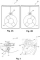
- the device 100 comprises a connector port 130, a regulator 140, an indicator 120, a manipulator 110 and a manipulator cover 115, beneath which, as shown in Figures 2A and 2B , a manipulator 110, here in the form of a handwheel, is arranged.
- a shutoff valve of the gas cylinder 150 can be opened and closed.
- Figure 2A a situation with a closed valve is shown
- Figure 2B a situation with an open valve is illustrated.
- the handwheel 110 is connected to the indicator 120 via a drive element such as a mechanism, an exemplary embodiment of which is depicted in Figure 3 and collectively referred to with 200.
- the mechanism 200 may comprise an indicating cylinder 210 which is rotatable around its vertical axis.
- a rotation of the indicating cylinder 210 may be effected by a Geneva gear 230, which is in engagement with a knob 212 protruding in a direction perpendicular to the vertical axis from the indicating cylinder 210.
- Rotational movement of the indicating cylinder may be limited, e.g.
- the Geneva gear 230 may be directly coupled to the handwheel 110, for example via a common axis, or may engage with the handwheel via a transfer means such as a toothed gear, a belt or similar means.
- the rotational movement of the indicating cylinder 210 may be aided and/or hindered by a torsion spring 216 or the like, so as to minimize play and/or required force.
- the indicating cylinder 210 can have an indicating label, e.g. with colour and/or text and/or symbolic representations printed on the surface.
- the label presented to the user e.g. through a window in a housing of the device 100, can indicate, for example, 'ON', showing the shutoff valve is open, or 'OFF', showing the shutoff valve is closed.
- This information may additionally or alternatively colour coded and/or represented by symbols.
- Said window in combination with the indicating cylinder 210 may form the indicator 120 mentioned herein before.
- the indicator 120 could also be used to display a status where the valve is not fully opened or closed by showing a graduated colour, for example red-green.
- the device 100 can also incorporate an electronic sensor (for example a hall sensor and/or a magnet) that monitors the drive element, e.g. the position of the Geneva gear 230.
- the electronic sensor can also be used to trigger a misuse alarm condition (e.g. handwheel closed, flow rate set) which could activate an audible and/or visual alarm.
- the indicator 120 may be arranged in different locations of the device, particularly in the vicinity of the regulator 140 and/or the manipulator 110. Particularly advantageous locations are outside an area covered by the cover 115, which may, for example, be attached for transport of fresh gas cylinders 150 and may be configured to be detached from the device, once it is in use, to indicate that a gas cylinder has already been opened.
- the cover 115 may be reusable so as to provide an additional element of security for the manipulator. For example, it may be helpful to cover the handwheel 110 after it has been opened to provide a psychological barrier for closing it during a stressful situation.
- the device 100 provides enhanced operating safety by clearly indicating the valve opening status at a location easily visible for a user at all times. This is of particular advantage in connection with medical gases such as oxygen, nitrous oxide or other therapeutic gases.
- the device 100 or its mechanism 200 may be used in connection with new gas containers 150 or retrofitted to existing systems, thereby reducing investment costs and environmental impact.
- the mechanism may at least partly consist of low cost materials such as thermoplastics, light metals or the like as well as combinations thereof.
- mechanism 200 alone or the device 100 may also be used in connection with other valves and is not limited to gas cylinders 150.
Landscapes
- Engineering & Computer Science (AREA)
- Mechanical Engineering (AREA)
- General Engineering & Computer Science (AREA)
- Filling Or Discharging Of Gas Storage Vessels (AREA)
Abstract
The invention proposes a device (100) for indicating a valve opening status, comprising a manipulator (110), configured to change an opening status of a valve, further comprising an indicator (120), configured to display an information on the opening status of the valve, and a drive element, configured to effect a change of the information displayed by the indicator (120) in reaction to a change of the opening status of the valve.
Description
- The present invention relates to a device for indicating a valve opening status according to the preamble of the main claim.
- Mobile medical oxygen is commonly delivered via cylinders with an integrated valve with integrated pressure regulator (VIPR). The VIPR typically comprises a valve and a handling device / guard. Various designs of VIPR and guard/handling device exist today. In the UK alone, there are approximately half a million oxygen VIPR in the market with a so-called '2 knob design' i.e. a safety shutoff valve (controlled by a handwheel) and used to isolate the valve from the high pressure cylinder, and a flowknob used to set discrete flow rates (typically in the range from 0.25 to 25 L/min).
- The present invention provides a device for indicating a valve opening status according to the main claim. Advantageous embodiments are subject-matter of the dependent claims as well as the following description.
- According to the invention, a device for indicating a valve opening status comprises a manipulator, configured to change an opening status of a valve, and is characterized by an indicator, configured to display an information on the opening status of the valve, and a drive element, configured to effect a change of the information displayed by the indicator in reaction to a change of the opening status of the valve. This enhances the operating safety, since the valve opening status is immediately recognisable from the indicator without the danger of misinterpretation as is the case when observing a position of the manipulator.
- Advantageously, the manipulator is at least partially and/or temporarily covered by a cover, wherein the cover is configured to not cover the indicator at least when covering the manipulator. This provides the advantage, that the information regarding the valve opening status cannot be hidden by the cover, which further enhances operating safety in that the manipulator is covered and therefore cannot be operated by accident while the in formation is still recognisable.
- The drive element preferably comprises a mechanism mechanically coupled to both the manipulator and the indicator, such that a movement of the manipulator effects a movement of the drive element and a movement of the drive element effects a change of the information displayed by the indicator. This means that by changing the valve opening status, the indicator automatically and reliably displays the correct information.
- Said mechanism advantageously comprises a Geneva gear. This is a simple and robust mechanism and thus ensures proper displaying of the information required.
- The manipulator preferably comprises a handling element of a gas container shutoff valve. Therefore, the indicator displays information on whether gas can be withdrawn from the container or not. This reduces the risk, for example, of setting a flow rate for gas withdrawal from an oxygen cylinder while the shutoff valve is closed. If that were done, a patient requiring oxygen might be harmed due to a lack of respiratory oxygen. Thus, the invention may save lives of patients with respiratory conditions requiring oxygen treatment.
- In advantageous embodiments, the device further comprises a regulator configured to regulate a gas flow and/or a gas pressure. Integrated valve and regulators are preferred for ease of use and intuitivity.
- Preferably, the indicator is arranged adjacent to said regulator. In such a case, on setting a flow rate and/or pressure to be effective downstream from the device, it is immediately evident, if the valve is opened or closed, so that an operation error becomes very unlikely.
- Further advantages and features of the invention will be described in the following with reference to the appended drawings.
-
-
Figure 1 shows an arrangement of an advantageous embodiment of a device according to the invention with a gas cylinder. -
Figures 2A and 2B show a partial side view of the device shown inFigure 1 . -
Figure 3 shows top and perspective sectional views of the device ofFigure 1 . - In
Figure 1 , an arrangement of an advantageous embodiment of a device according to the invention and a gas cylinder is shown. The device is collectively referred to with 100, the gas cylinder with 150. - In
Figures 2A, 2B and 3 , more detailed partial views of thedevice 100 are depicted. Functionally corresponding elements are referred to with the same reference numerals throughout the drawings. - The
device 100 comprises aconnector port 130, aregulator 140, anindicator 120, amanipulator 110 and amanipulator cover 115, beneath which, as shown inFigures 2A and 2B , amanipulator 110, here in the form of a handwheel, is arranged. By turning thehandwheel 110, a shutoff valve of thegas cylinder 150 can be opened and closed. InFigure 2A , a situation with a closed valve is shown, whereas inFigure 2B , a situation with an open valve is illustrated. - The
handwheel 110 is connected to theindicator 120 via a drive element such as a mechanism, an exemplary embodiment of which is depicted inFigure 3 and collectively referred to with 200. Themechanism 200, as shown inFigure 3 in top (left) and perspective (right) sectional views, may comprise an indicatingcylinder 210 which is rotatable around its vertical axis. A rotation of the indicatingcylinder 210 may be effected by a Genevagear 230, which is in engagement with aknob 212 protruding in a direction perpendicular to the vertical axis from the indicatingcylinder 210. Rotational movement of the indicating cylinder may be limited, e.g. by anend stop 214 also protruding in a radial direction from the indicatingcylinder 210. The Genevagear 230 may be directly coupled to thehandwheel 110, for example via a common axis, or may engage with the handwheel via a transfer means such as a toothed gear, a belt or similar means. The rotational movement of the indicatingcylinder 210 may be aided and/or hindered by atorsion spring 216 or the like, so as to minimize play and/or required force. - The indicating
cylinder 210 can have an indicating label, e.g. with colour and/or text and/or symbolic representations printed on the surface. As the indicatingcylinder 210 rotates, the label presented to the user, e.g. through a window in a housing of thedevice 100, can indicate, for example, 'ON', showing the shutoff valve is open, or 'OFF', showing the shutoff valve is closed. This information may additionally or alternatively colour coded and/or represented by symbols. Said window in combination with the indicatingcylinder 210 may form theindicator 120 mentioned herein before. - The
indicator 120 could also be used to display a status where the valve is not fully opened or closed by showing a graduated colour, for example red-green. - The
device 100 can also incorporate an electronic sensor (for example a hall sensor and/or a magnet) that monitors the drive element, e.g. the position of the Genevagear 230. The electronic sensor can also be used to trigger a misuse alarm condition (e.g. handwheel closed, flow rate set) which could activate an audible and/or visual alarm. - As shown in
Figure 1 , theindicator 120 may be arranged in different locations of the device, particularly in the vicinity of theregulator 140 and/or themanipulator 110. Particularly advantageous locations are outside an area covered by thecover 115, which may, for example, be attached for transport offresh gas cylinders 150 and may be configured to be detached from the device, once it is in use, to indicate that a gas cylinder has already been opened. In other embodiments, thecover 115 may be reusable so as to provide an additional element of security for the manipulator. For example, it may be helpful to cover thehandwheel 110 after it has been opened to provide a psychological barrier for closing it during a stressful situation. - In general, the
device 100 provides enhanced operating safety by clearly indicating the valve opening status at a location easily visible for a user at all times. This is of particular advantage in connection with medical gases such as oxygen, nitrous oxide or other therapeutic gases. - The
device 100 or itsmechanism 200 may be used in connection withnew gas containers 150 or retrofitted to existing systems, thereby reducing investment costs and environmental impact. The mechanism may at least partly consist of low cost materials such as thermoplastics, light metals or the like as well as combinations thereof. - It is to be understood that the
mechanism 200 alone or thedevice 100 may also be used in connection with other valves and is not limited togas cylinders 150.
Claims (7)
- Device (100) for indicating a valve opening status, comprising
a manipulator (110), configured to change an opening status of a valve, characterized byan indicator (120), configured to display an information on the opening status of the valve, anda drive element, configured to effect a change of the information displayed by the indicator (120) in reaction to a change of the opening status of the valve. - Device (100) according to claim 1, wherein the manipulator (110) is at least partially and/or temporarily covered by a cover (115), wherein the cover (115) is configured to not cover the indicator (120) at least when covering the manipulator (110).
- Device (100) according to claim 1 or 2, wherein the drive element comprises a mechanism (200) mechanically coupled to both the manipulator (110) and the indicator (120), such that a movement of the manipulator (110) effects a movement of the drive element and a movement of the drive element effects a change of the information displayed by the indicator (120).
- Device (100) according to claim 3, wherein the mechanism (200) comprises a Geneva gear (230).
- Device (100) according to any of the preceding claims, wherein the manipulator (110) comprises a handling element of a gas container shutoff valve.
- Device (100) according to any of the preceding claims, further comprising a regulator (140) configured to regulate a gas flow and/or a gas pressure.
- Device (100) according to claim 6, wherein the indicator (120) is arranged adjacent to the regulator (140).
Priority Applications (1)
| Application Number | Priority Date | Filing Date | Title |
|---|---|---|---|
| EP21020567.0A EP4180708A1 (en) | 2021-11-16 | 2021-11-16 | Device for indicating a valve opening status |
Applications Claiming Priority (1)
| Application Number | Priority Date | Filing Date | Title |
|---|---|---|---|
| EP21020567.0A EP4180708A1 (en) | 2021-11-16 | 2021-11-16 | Device for indicating a valve opening status |
Publications (1)
| Publication Number | Publication Date |
|---|---|
| EP4180708A1 true EP4180708A1 (en) | 2023-05-17 |
Family
ID=78822411
Family Applications (1)
| Application Number | Title | Priority Date | Filing Date |
|---|---|---|---|
| EP21020567.0A Withdrawn EP4180708A1 (en) | 2021-11-16 | 2021-11-16 | Device for indicating a valve opening status |
Country Status (1)
| Country | Link |
|---|---|
| EP (1) | EP4180708A1 (en) |
Citations (2)
| Publication number | Priority date | Publication date | Assignee | Title |
|---|---|---|---|---|
| FR2774452A1 (en) * | 1998-01-30 | 1999-08-06 | Air Liquide | Protective cap for gas bottles |
| US20200088318A1 (en) * | 2018-09-13 | 2020-03-19 | Entegris, Inc. | Valve system with position indicator |
-
2021
- 2021-11-16 EP EP21020567.0A patent/EP4180708A1/en not_active Withdrawn
Patent Citations (2)
| Publication number | Priority date | Publication date | Assignee | Title |
|---|---|---|---|---|
| FR2774452A1 (en) * | 1998-01-30 | 1999-08-06 | Air Liquide | Protective cap for gas bottles |
| US20200088318A1 (en) * | 2018-09-13 | 2020-03-19 | Entegris, Inc. | Valve system with position indicator |
Similar Documents
| Publication | Publication Date | Title |
|---|---|---|
| EP1596913B1 (en) | Dispensing apparatus | |
| JP4426565B2 (en) | Dosing device | |
| US7418961B2 (en) | Dispensing apparatus | |
| US20100186837A1 (en) | Tap For Pressurized Gas Cylinder | |
| EP1933946B1 (en) | Improved breathing mask and regulator for aircraft | |
| EP0451090B1 (en) | Resuscitation and ventilation device | |
| JPH03173579A (en) | Intravenous drip device | |
| WO2004071561A1 (en) | Dispensing apparatus | |
| EP2431065B1 (en) | Arrangement for ventilating lungs | |
| BRPI0722199B1 (en) | BREATHING MASK WITH OXYGEN CONSUMPTION REDUCTION. | |
| US7677244B2 (en) | Drug delivery device and method | |
| WO2000064522A9 (en) | Treatment of carbon monoxide poisoning | |
| CN107960114B (en) | Modular gas extraction system for compressed gas cylinders | |
| WO2006117591A1 (en) | Breathing assistance device comprising a gas regulating valve and associated breathing assistance method | |
| KR950014994B1 (en) | Container valve with residual pressure indicator for portable oxygen-suction cylinder | |
| US11344695B2 (en) | Gas flow arrestor | |
| US20120247587A1 (en) | Visual indicator for air tank valve handle | |
| JP3676514B2 (en) | Medical valve device | |
| GB2398250A (en) | Inhaler with display and single operating button | |
| ES2292222T3 (en) | SET OF FAUCET FOR GAS BOTTLE. | |
| JP4856996B2 (en) | Container valve | |
| KR20230057740A (en) | Chamber service lock with safety locking device | |
| CA2371161C (en) | Treatment of carbon monoxide poisoning | |
| Karchner et al. | Failure to Ventilate with the Dräger Apollo® Anesthesia Workstation | |
| CN119022076A (en) | Valves with integrated pressure regulator |
Legal Events
| Date | Code | Title | Description |
|---|---|---|---|
| PUAI | Public reference made under article 153(3) epc to a published international application that has entered the european phase |
Free format text: ORIGINAL CODE: 0009012 |
|
| STAA | Information on the status of an ep patent application or granted ep patent |
Free format text: STATUS: THE APPLICATION HAS BEEN PUBLISHED |
|
| AK | Designated contracting states |
Kind code of ref document: A1 Designated state(s): AL AT BE BG CH CY CZ DE DK EE ES FI FR GB GR HR HU IE IS IT LI LT LU LV MC MK MT NL NO PL PT RO RS SE SI SK SM TR |
|
| STAA | Information on the status of an ep patent application or granted ep patent |
Free format text: STATUS: THE APPLICATION IS DEEMED TO BE WITHDRAWN |
|
| 18D | Application deemed to be withdrawn |
Effective date: 20231118 |