EP4180692A1 - Two-stage speed-change output device and electric vehicle using same - Google Patents
Two-stage speed-change output device and electric vehicle using same Download PDFInfo
- Publication number
- EP4180692A1 EP4180692A1 EP22206567.4A EP22206567A EP4180692A1 EP 4180692 A1 EP4180692 A1 EP 4180692A1 EP 22206567 A EP22206567 A EP 22206567A EP 4180692 A1 EP4180692 A1 EP 4180692A1
- Authority
- EP
- European Patent Office
- Prior art keywords
- speed
- change
- assembly
- shell
- wheel hub
- Prior art date
- Legal status (The legal status is an assumption and is not a legal conclusion. Google has not performed a legal analysis and makes no representation as to the accuracy of the status listed.)
- Pending
Links
Images





Classifications
-
- B—PERFORMING OPERATIONS; TRANSPORTING
- B60—VEHICLES IN GENERAL
- B60K—ARRANGEMENT OR MOUNTING OF PROPULSION UNITS OR OF TRANSMISSIONS IN VEHICLES; ARRANGEMENT OR MOUNTING OF PLURAL DIVERSE PRIME-MOVERS IN VEHICLES; AUXILIARY DRIVES FOR VEHICLES; INSTRUMENTATION OR DASHBOARDS FOR VEHICLES; ARRANGEMENTS IN CONNECTION WITH COOLING, AIR INTAKE, GAS EXHAUST OR FUEL SUPPLY OF PROPULSION UNITS IN VEHICLES
- B60K17/00—Arrangement or mounting of transmissions in vehicles
- B60K17/04—Arrangement or mounting of transmissions in vehicles characterised by arrangement, location or kind of gearing
- B60K17/043—Transmission unit disposed in on near the vehicle wheel, or between the differential gear unit and the wheel
- B60K17/046—Transmission unit disposed in on near the vehicle wheel, or between the differential gear unit and the wheel with planetary gearing having orbital motion
-
- B—PERFORMING OPERATIONS; TRANSPORTING
- B62—LAND VEHICLES FOR TRAVELLING OTHERWISE THAN ON RAILS
- B62M—RIDER PROPULSION OF WHEELED VEHICLES OR SLEDGES; POWERED PROPULSION OF SLEDGES OR SINGLE-TRACK CYCLES; TRANSMISSIONS SPECIALLY ADAPTED FOR SUCH VEHICLES
- B62M6/00—Rider propulsion of wheeled vehicles with additional source of power, e.g. combustion engine or electric motor
- B62M6/40—Rider propelled cycles with auxiliary electric motor
- B62M6/75—Rider propelled cycles with auxiliary electric motor power-driven by friction rollers or gears engaging the ground wheel
-
- B—PERFORMING OPERATIONS; TRANSPORTING
- B60—VEHICLES IN GENERAL
- B60B—VEHICLE WHEELS; CASTORS; AXLES FOR WHEELS OR CASTORS; INCREASING WHEEL ADHESION
- B60B27/00—Hubs
- B60B27/0015—Hubs for driven wheels
- B60B27/0021—Hubs for driven wheels characterised by torque transmission means from drive axle
-
- B—PERFORMING OPERATIONS; TRANSPORTING
- B60—VEHICLES IN GENERAL
- B60K—ARRANGEMENT OR MOUNTING OF PROPULSION UNITS OR OF TRANSMISSIONS IN VEHICLES; ARRANGEMENT OR MOUNTING OF PLURAL DIVERSE PRIME-MOVERS IN VEHICLES; AUXILIARY DRIVES FOR VEHICLES; INSTRUMENTATION OR DASHBOARDS FOR VEHICLES; ARRANGEMENTS IN CONNECTION WITH COOLING, AIR INTAKE, GAS EXHAUST OR FUEL SUPPLY OF PROPULSION UNITS IN VEHICLES
- B60K17/00—Arrangement or mounting of transmissions in vehicles
- B60K17/02—Arrangement or mounting of transmissions in vehicles characterised by arrangement, location, or kind of clutch
-
- B—PERFORMING OPERATIONS; TRANSPORTING
- B60—VEHICLES IN GENERAL
- B60K—ARRANGEMENT OR MOUNTING OF PROPULSION UNITS OR OF TRANSMISSIONS IN VEHICLES; ARRANGEMENT OR MOUNTING OF PLURAL DIVERSE PRIME-MOVERS IN VEHICLES; AUXILIARY DRIVES FOR VEHICLES; INSTRUMENTATION OR DASHBOARDS FOR VEHICLES; ARRANGEMENTS IN CONNECTION WITH COOLING, AIR INTAKE, GAS EXHAUST OR FUEL SUPPLY OF PROPULSION UNITS IN VEHICLES
- B60K17/00—Arrangement or mounting of transmissions in vehicles
- B60K17/04—Arrangement or mounting of transmissions in vehicles characterised by arrangement, location or kind of gearing
- B60K17/06—Arrangement or mounting of transmissions in vehicles characterised by arrangement, location or kind of gearing of change-speed gearing
- B60K17/08—Arrangement or mounting of transmissions in vehicles characterised by arrangement, location or kind of gearing of change-speed gearing of mechanical type
-
- B—PERFORMING OPERATIONS; TRANSPORTING
- B60—VEHICLES IN GENERAL
- B60K—ARRANGEMENT OR MOUNTING OF PROPULSION UNITS OR OF TRANSMISSIONS IN VEHICLES; ARRANGEMENT OR MOUNTING OF PLURAL DIVERSE PRIME-MOVERS IN VEHICLES; AUXILIARY DRIVES FOR VEHICLES; INSTRUMENTATION OR DASHBOARDS FOR VEHICLES; ARRANGEMENTS IN CONNECTION WITH COOLING, AIR INTAKE, GAS EXHAUST OR FUEL SUPPLY OF PROPULSION UNITS IN VEHICLES
- B60K7/00—Disposition of motor in, or adjacent to, traction wheel
- B60K7/0007—Disposition of motor in, or adjacent to, traction wheel the motor being electric
-
- B—PERFORMING OPERATIONS; TRANSPORTING
- B62—LAND VEHICLES FOR TRAVELLING OTHERWISE THAN ON RAILS
- B62M—RIDER PROPULSION OF WHEELED VEHICLES OR SLEDGES; POWERED PROPULSION OF SLEDGES OR SINGLE-TRACK CYCLES; TRANSMISSIONS SPECIALLY ADAPTED FOR SUCH VEHICLES
- B62M11/00—Transmissions characterised by the use of interengaging toothed wheels or frictionally-engaging wheels
- B62M11/04—Transmissions characterised by the use of interengaging toothed wheels or frictionally-engaging wheels of changeable ratio
-
- B—PERFORMING OPERATIONS; TRANSPORTING
- B62—LAND VEHICLES FOR TRAVELLING OTHERWISE THAN ON RAILS
- B62M—RIDER PROPULSION OF WHEELED VEHICLES OR SLEDGES; POWERED PROPULSION OF SLEDGES OR SINGLE-TRACK CYCLES; TRANSMISSIONS SPECIALLY ADAPTED FOR SUCH VEHICLES
- B62M11/00—Transmissions characterised by the use of interengaging toothed wheels or frictionally-engaging wheels
- B62M11/04—Transmissions characterised by the use of interengaging toothed wheels or frictionally-engaging wheels of changeable ratio
- B62M11/14—Transmissions characterised by the use of interengaging toothed wheels or frictionally-engaging wheels of changeable ratio with planetary gears
-
- B—PERFORMING OPERATIONS; TRANSPORTING
- B62—LAND VEHICLES FOR TRAVELLING OTHERWISE THAN ON RAILS
- B62M—RIDER PROPULSION OF WHEELED VEHICLES OR SLEDGES; POWERED PROPULSION OF SLEDGES OR SINGLE-TRACK CYCLES; TRANSMISSIONS SPECIALLY ADAPTED FOR SUCH VEHICLES
- B62M11/00—Transmissions characterised by the use of interengaging toothed wheels or frictionally-engaging wheels
- B62M11/04—Transmissions characterised by the use of interengaging toothed wheels or frictionally-engaging wheels of changeable ratio
- B62M11/14—Transmissions characterised by the use of interengaging toothed wheels or frictionally-engaging wheels of changeable ratio with planetary gears
- B62M11/18—Transmissions characterised by the use of interengaging toothed wheels or frictionally-engaging wheels of changeable ratio with planetary gears with a plurality of planetary gear units
-
- B—PERFORMING OPERATIONS; TRANSPORTING
- B62—LAND VEHICLES FOR TRAVELLING OTHERWISE THAN ON RAILS
- B62M—RIDER PROPULSION OF WHEELED VEHICLES OR SLEDGES; POWERED PROPULSION OF SLEDGES OR SINGLE-TRACK CYCLES; TRANSMISSIONS SPECIALLY ADAPTED FOR SUCH VEHICLES
- B62M6/00—Rider propulsion of wheeled vehicles with additional source of power, e.g. combustion engine or electric motor
- B62M6/40—Rider propelled cycles with auxiliary electric motor
- B62M6/45—Control or actuating devices therefor
-
- B—PERFORMING OPERATIONS; TRANSPORTING
- B62—LAND VEHICLES FOR TRAVELLING OTHERWISE THAN ON RAILS
- B62M—RIDER PROPULSION OF WHEELED VEHICLES OR SLEDGES; POWERED PROPULSION OF SLEDGES OR SINGLE-TRACK CYCLES; TRANSMISSIONS SPECIALLY ADAPTED FOR SUCH VEHICLES
- B62M6/00—Rider propulsion of wheeled vehicles with additional source of power, e.g. combustion engine or electric motor
- B62M6/40—Rider propelled cycles with auxiliary electric motor
- B62M6/60—Rider propelled cycles with auxiliary electric motor power-driven at axle parts
-
- B—PERFORMING OPERATIONS; TRANSPORTING
- B62—LAND VEHICLES FOR TRAVELLING OTHERWISE THAN ON RAILS
- B62M—RIDER PROPULSION OF WHEELED VEHICLES OR SLEDGES; POWERED PROPULSION OF SLEDGES OR SINGLE-TRACK CYCLES; TRANSMISSIONS SPECIALLY ADAPTED FOR SUCH VEHICLES
- B62M6/00—Rider propulsion of wheeled vehicles with additional source of power, e.g. combustion engine or electric motor
- B62M6/40—Rider propelled cycles with auxiliary electric motor
- B62M6/60—Rider propelled cycles with auxiliary electric motor power-driven at axle parts
- B62M6/65—Rider propelled cycles with auxiliary electric motor power-driven at axle parts with axle and driving shaft arranged coaxially
-
- F—MECHANICAL ENGINEERING; LIGHTING; HEATING; WEAPONS; BLASTING
- F16—ENGINEERING ELEMENTS AND UNITS; GENERAL MEASURES FOR PRODUCING AND MAINTAINING EFFECTIVE FUNCTIONING OF MACHINES OR INSTALLATIONS; THERMAL INSULATION IN GENERAL
- F16H—GEARING
- F16H3/00—Toothed gearings for conveying rotary motion with variable gear ratio or for reversing rotary motion
- F16H3/003—Toothed gearings for conveying rotary motion with variable gear ratio or for reversing rotary motion the gear ratio being changed by inversion of torque direction
- F16H3/005—Toothed gearings for conveying rotary motion with variable gear ratio or for reversing rotary motion the gear ratio being changed by inversion of torque direction for gearings using gears having orbital motion
-
- H—ELECTRICITY
- H02—GENERATION; CONVERSION OR DISTRIBUTION OF ELECTRIC POWER
- H02K—DYNAMO-ELECTRIC MACHINES
- H02K7/00—Arrangements for handling mechanical energy structurally associated with dynamo-electric machines, e.g. structural association with mechanical driving motors or auxiliary dynamo-electric machines
- H02K7/10—Structural association with clutches, brakes, gears, pulleys or mechanical starters
- H02K7/116—Structural association with clutches, brakes, gears, pulleys or mechanical starters with gears
-
- B—PERFORMING OPERATIONS; TRANSPORTING
- B60—VEHICLES IN GENERAL
- B60K—ARRANGEMENT OR MOUNTING OF PROPULSION UNITS OR OF TRANSMISSIONS IN VEHICLES; ARRANGEMENT OR MOUNTING OF PLURAL DIVERSE PRIME-MOVERS IN VEHICLES; AUXILIARY DRIVES FOR VEHICLES; INSTRUMENTATION OR DASHBOARDS FOR VEHICLES; ARRANGEMENTS IN CONNECTION WITH COOLING, AIR INTAKE, GAS EXHAUST OR FUEL SUPPLY OF PROPULSION UNITS IN VEHICLES
- B60K7/00—Disposition of motor in, or adjacent to, traction wheel
- B60K2007/0038—Disposition of motor in, or adjacent to, traction wheel the motor moving together with the wheel axle
-
- B—PERFORMING OPERATIONS; TRANSPORTING
- B60—VEHICLES IN GENERAL
- B60K—ARRANGEMENT OR MOUNTING OF PROPULSION UNITS OR OF TRANSMISSIONS IN VEHICLES; ARRANGEMENT OR MOUNTING OF PLURAL DIVERSE PRIME-MOVERS IN VEHICLES; AUXILIARY DRIVES FOR VEHICLES; INSTRUMENTATION OR DASHBOARDS FOR VEHICLES; ARRANGEMENTS IN CONNECTION WITH COOLING, AIR INTAKE, GAS EXHAUST OR FUEL SUPPLY OF PROPULSION UNITS IN VEHICLES
- B60K7/00—Disposition of motor in, or adjacent to, traction wheel
- B60K2007/0092—Disposition of motor in, or adjacent to, traction wheel the motor axle being coaxial to the wheel axle
-
- B—PERFORMING OPERATIONS; TRANSPORTING
- B60—VEHICLES IN GENERAL
- B60Y—INDEXING SCHEME RELATING TO ASPECTS CROSS-CUTTING VEHICLE TECHNOLOGY
- B60Y2200/00—Type of vehicle
- B60Y2200/10—Road Vehicles
- B60Y2200/13—Bicycles; Tricycles
-
- B—PERFORMING OPERATIONS; TRANSPORTING
- B60—VEHICLES IN GENERAL
- B60Y—INDEXING SCHEME RELATING TO ASPECTS CROSS-CUTTING VEHICLE TECHNOLOGY
- B60Y2400/00—Special features of vehicle units
- B60Y2400/42—Clutches or brakes
- B60Y2400/427—One-way clutches
-
- B—PERFORMING OPERATIONS; TRANSPORTING
- B60—VEHICLES IN GENERAL
- B60Y—INDEXING SCHEME RELATING TO ASPECTS CROSS-CUTTING VEHICLE TECHNOLOGY
- B60Y2400/00—Special features of vehicle units
- B60Y2400/70—Gearings
- B60Y2400/73—Planetary gearings
-
- B—PERFORMING OPERATIONS; TRANSPORTING
- B62—LAND VEHICLES FOR TRAVELLING OTHERWISE THAN ON RAILS
- B62M—RIDER PROPULSION OF WHEELED VEHICLES OR SLEDGES; POWERED PROPULSION OF SLEDGES OR SINGLE-TRACK CYCLES; TRANSMISSIONS SPECIALLY ADAPTED FOR SUCH VEHICLES
- B62M11/00—Transmissions characterised by the use of interengaging toothed wheels or frictionally-engaging wheels
- B62M11/04—Transmissions characterised by the use of interengaging toothed wheels or frictionally-engaging wheels of changeable ratio
- B62M11/14—Transmissions characterised by the use of interengaging toothed wheels or frictionally-engaging wheels of changeable ratio with planetary gears
- B62M11/16—Transmissions characterised by the use of interengaging toothed wheels or frictionally-engaging wheels of changeable ratio with planetary gears built in, or adjacent to, the ground-wheel hub
-
- F—MECHANICAL ENGINEERING; LIGHTING; HEATING; WEAPONS; BLASTING
- F16—ENGINEERING ELEMENTS AND UNITS; GENERAL MEASURES FOR PRODUCING AND MAINTAINING EFFECTIVE FUNCTIONING OF MACHINES OR INSTALLATIONS; THERMAL INSULATION IN GENERAL
- F16H—GEARING
- F16H2200/00—Transmissions for multiple ratios
- F16H2200/0021—Transmissions for multiple ratios specially adapted for electric vehicles
-
- F—MECHANICAL ENGINEERING; LIGHTING; HEATING; WEAPONS; BLASTING
- F16—ENGINEERING ELEMENTS AND UNITS; GENERAL MEASURES FOR PRODUCING AND MAINTAINING EFFECTIVE FUNCTIONING OF MACHINES OR INSTALLATIONS; THERMAL INSULATION IN GENERAL
- F16H—GEARING
- F16H2200/00—Transmissions for multiple ratios
- F16H2200/003—Transmissions for multiple ratios characterised by the number of forward speeds
- F16H2200/0034—Transmissions for multiple ratios characterised by the number of forward speeds the gear ratios comprising two forward speeds
-
- F—MECHANICAL ENGINEERING; LIGHTING; HEATING; WEAPONS; BLASTING
- F16—ENGINEERING ELEMENTS AND UNITS; GENERAL MEASURES FOR PRODUCING AND MAINTAINING EFFECTIVE FUNCTIONING OF MACHINES OR INSTALLATIONS; THERMAL INSULATION IN GENERAL
- F16H—GEARING
- F16H2200/00—Transmissions for multiple ratios
- F16H2200/20—Transmissions using gears with orbital motion
- F16H2200/2002—Transmissions using gears with orbital motion characterised by the number of sets of orbital gears
- F16H2200/2007—Transmissions using gears with orbital motion characterised by the number of sets of orbital gears with two sets of orbital gears
-
- F—MECHANICAL ENGINEERING; LIGHTING; HEATING; WEAPONS; BLASTING
- F16—ENGINEERING ELEMENTS AND UNITS; GENERAL MEASURES FOR PRODUCING AND MAINTAINING EFFECTIVE FUNCTIONING OF MACHINES OR INSTALLATIONS; THERMAL INSULATION IN GENERAL
- F16H—GEARING
- F16H2200/00—Transmissions for multiple ratios
- F16H2200/20—Transmissions using gears with orbital motion
- F16H2200/2002—Transmissions using gears with orbital motion characterised by the number of sets of orbital gears
- F16H2200/201—Transmissions using gears with orbital motion characterised by the number of sets of orbital gears with three sets of orbital gears
-
- F—MECHANICAL ENGINEERING; LIGHTING; HEATING; WEAPONS; BLASTING
- F16—ENGINEERING ELEMENTS AND UNITS; GENERAL MEASURES FOR PRODUCING AND MAINTAINING EFFECTIVE FUNCTIONING OF MACHINES OR INSTALLATIONS; THERMAL INSULATION IN GENERAL
- F16H—GEARING
- F16H2200/00—Transmissions for multiple ratios
- F16H2200/20—Transmissions using gears with orbital motion
- F16H2200/203—Transmissions using gears with orbital motion characterised by the engaging friction means not of the freewheel type, e.g. friction clutches or brakes
- F16H2200/2069—Transmissions using gears with orbital motion characterised by the engaging friction means not of the freewheel type, e.g. friction clutches or brakes using two freewheel mechanism
-
- F—MECHANICAL ENGINEERING; LIGHTING; HEATING; WEAPONS; BLASTING
- F16—ENGINEERING ELEMENTS AND UNITS; GENERAL MEASURES FOR PRODUCING AND MAINTAINING EFFECTIVE FUNCTIONING OF MACHINES OR INSTALLATIONS; THERMAL INSULATION IN GENERAL
- F16H—GEARING
- F16H2200/00—Transmissions for multiple ratios
- F16H2200/20—Transmissions using gears with orbital motion
- F16H2200/203—Transmissions using gears with orbital motion characterised by the engaging friction means not of the freewheel type, e.g. friction clutches or brakes
- F16H2200/2071—Transmissions using gears with orbital motion characterised by the engaging friction means not of the freewheel type, e.g. friction clutches or brakes using three freewheel mechanism
-
- F—MECHANICAL ENGINEERING; LIGHTING; HEATING; WEAPONS; BLASTING
- F16—ENGINEERING ELEMENTS AND UNITS; GENERAL MEASURES FOR PRODUCING AND MAINTAINING EFFECTIVE FUNCTIONING OF MACHINES OR INSTALLATIONS; THERMAL INSULATION IN GENERAL
- F16H—GEARING
- F16H2200/00—Transmissions for multiple ratios
- F16H2200/20—Transmissions using gears with orbital motion
- F16H2200/2079—Transmissions using gears with orbital motion using freewheel type mechanisms, e.g. freewheel clutches
- F16H2200/2084—Transmissions using gears with orbital motion using freewheel type mechanisms, e.g. freewheel clutches two freewheel mechanisms
-
- F—MECHANICAL ENGINEERING; LIGHTING; HEATING; WEAPONS; BLASTING
- F16—ENGINEERING ELEMENTS AND UNITS; GENERAL MEASURES FOR PRODUCING AND MAINTAINING EFFECTIVE FUNCTIONING OF MACHINES OR INSTALLATIONS; THERMAL INSULATION IN GENERAL
- F16H—GEARING
- F16H2200/00—Transmissions for multiple ratios
- F16H2200/20—Transmissions using gears with orbital motion
- F16H2200/2079—Transmissions using gears with orbital motion using freewheel type mechanisms, e.g. freewheel clutches
- F16H2200/2087—Transmissions using gears with orbital motion using freewheel type mechanisms, e.g. freewheel clutches three freewheel mechanisms
-
- Y—GENERAL TAGGING OF NEW TECHNOLOGICAL DEVELOPMENTS; GENERAL TAGGING OF CROSS-SECTIONAL TECHNOLOGIES SPANNING OVER SEVERAL SECTIONS OF THE IPC; TECHNICAL SUBJECTS COVERED BY FORMER USPC CROSS-REFERENCE ART COLLECTIONS [XRACs] AND DIGESTS
- Y02—TECHNOLOGIES OR APPLICATIONS FOR MITIGATION OR ADAPTATION AGAINST CLIMATE CHANGE
- Y02T—CLIMATE CHANGE MITIGATION TECHNOLOGIES RELATED TO TRANSPORTATION
- Y02T10/00—Road transport of goods or passengers
- Y02T10/60—Other road transportation technologies with climate change mitigation effect
- Y02T10/72—Electric energy management in electromobility
Definitions
- the present invention relates generally to the technical field of speed change for electric vehicles.
- Small electric vehicles are primarily power-assisted bicycles or electric bicycles, of which a driving source involves a motor assembly that is operable to drive wheels.
- the motor assembly is mounted on a vehicle frame and is connectable, by means of an output wheel (which can be a toothed wheel or a frictional wheel), with a transmission assembly arranged on a crankshaft (of a power-assisted bicycle) or a vehicle wheel hub (of an electric vehicle), so as to fulfill the purpose of assisted driving.
- the motor assembly and the transmission assembly are arranged separately, the number of the assemblies is large, occupying a large space, and inevitably increasing costs and difficulty of fabrication, and also adding vehicle loading and causing additional consumption of energy.
- the electric vehicle may be necessarily and additionally equipped with a speed change mechanism coupled to an output spindle of the motor assembly, and a speed change control unit is involved to conduct switching between various speeds.
- a speed change mechanism coupled to an output spindle of the motor assembly
- a speed change control unit is involved to conduct switching between various speeds.
- the primary objective of the present invention is to provide a two-stage speed-change output device, which realizes speed change of two stages by making use of forward and reverse rotations of a motor, exhibiting an effectiveness of easy operation.
- a second objective of the present invention is to provide an electric vehicle that uses a two-stage speed-change output device, in which the two-stage speed-change output device occupies a relatively small amount of space and is applicable to driving and speed changing for a small-sized electric vehicle, realizing great enhancement of the utilization thereof.
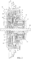
- a two-stage speed-change output device is constructed as shown in FIGS. 1 and 2 , and comprises a main axle 100, a motor assembly 10, a first speed-change assembly 20, a second speed-change assembly 30, and an output shell 40.
- the motor assembly 10 is operable to drive and rotate the first speed-change assembly 20 in a reverse or backward direction and to drive and rotate the second speed-change assembly 30 in a forward direction to allow the first and second speed-change assemblies 20, 30 to individually drive the output shell 40 in the same direction, so that the two-stage speed-change output device may carry out switching for two-stage speed change by using the forward and backward rotations of the motor assembly 10.
- the motor assembly 10 includes a main axle 100 on which an input sleeve 11 is rotatably mounted by means of a plurality of bearings.
- An electromagnetic mechanism 12 is mounted to an end of the input sleeve 11, so that the electromagnetic mechanism 12, when electrified and energized, and thus excited, drives the input sleeve 11 to rotate forward and backward relative to the main axle 100.
- the motor assembly 10 comprises an external motor housing 13 mounted on the main axle 100 at an outer side of the electromagnetic mechanism 12, and the motor assembly 10 comprises an internal motor housing 14 arranged at an inner side of the electromagnetic mechanism 12 to be combined with the external motor housing 13, wherein an axle seat 15, which is rotatably mounted on the input sleeve 11, is fit in and mounted to a center of the internal motor housing 14, so that the input sleeve 11 extends through and projects out of the internal motor housing 14 to drive the first and second speed-change assemblies 20, 30.
- the first speed-change assembly 20 is arranged between the main axle 100 and a corresponding end of the input sleeve 11 that extends out of the motor assembly 10.
- the first speed-change assembly 20 comprises a first carrier frame 21 that is fixed to the end of the input sleeve 11 by a sleeve fastener 16.
- the first carrier frame 21 has two opposite surfaces on which a first planet group 22 and a second planet group 23 are respectively arranged.
- the first and second planet groups 22, 23 each comprise a plurality of first planets 220 and second planets 230 of the same contour.
- the first and second planets 220, 230 are respectively fastened to each other, so that the first and second planets 220, 230 are individually rotatable (spinning), in the same direction and in a synchronized manner, on the first carrier frame 21. Further, a first sun gear 24 is fixed on the main axle 100 and in mating engagement with each of the first planets 220 of the first planet group 22 (as shown in FIG. 7 ). A first shell 25 is rotatably mounted on an outer circumference of the first carrier frame 21 by means of bead groups on two sides thereof.
- One side of the first shell 25 that is opposite to the second speed-change assembly 30 is provided with a shell cover 250 fastened thereto for constraining or positioning the bead groups, and on a surface of an opposite side of the first shell 25, a transmission wheel disc 26 that is rotatably mounted on the input sleeve 11 is fixed .
- the transmission wheel disc 26 is provided, on a center thereof, with a second sun gear 27 and a third sun gear 28 that are respectively arranged on two opposite sides thereof, wherein the second sun gear 27 of the transmission wheel disc 26 is in mating engagement with each of the second planets 230 of the second planet group 23 (as shown in FIG. 8 ).
- the third sun gear 28 of the transmission wheel disc 26 is connected with the second speed-change assembly 30, so that an input power that is input through the input sleeve 11 is transmitted through the first speed-change assembly 20 to the second speed-change assembly 30.
- a first one-way clutching element 29 is fit on an outer circumference of the first shell 25 (as shown in FIG. 7 ).
- the first one-way clutching element 29 is operable in either the forward direction or the backward direction, and in the present invention, a primary example for implementing the first one-way clutching element 29 is operating in the forward direction and idling in the backward direction.
- the output shell 40 is fit on an outer circumference of the first one-way clutching element 29, so that the input power is transmitted through the input sleeve 11, the first and second planet groups 22, 23 of the first carrier frame 21, the transmission wheel disc 26, the first shell 25, and the first one-way clutching element 29 to be outputted through the output shell 40.
- the second speed-change assembly 30 is arranged between the first speed-change assembly 20 and the motor assembly 10.
- the second speed-change assembly 30 comprises a second carrier frame 31 that is mounted on the axle seat 15 of the motor assembly 10.
- a third planet group 32 is arranged on a surface of the second carrier frame 31 that corresponds to the first speed-change assembly 20, and the third planet group 32 comprises a plurality of third planets 320 that are of the same contour.
- Each of the third planets 320 of the third planet group 32 is in mating engagement with the third sun gear 28 of the transmission wheel disc 26 of the first speed-change assembly 20, so that the transmission wheel disc 26 drives each of the third planets 320 of the third planet group 32 to rotate.
- a second shell 33 is rotatably mounted on an outer circumference of the second carrier frame 31 by means of bead groups on two sides thereof.
- One side of the second carrier frame 31 that is opposite to the first speed-change assembly 20 is provided with a shell cover 330 fastened thereto for constraining or positioning the bead groups, and the second shell 33 is provided, on an inner circumference thereof, with an internal ring toothed section 331 that is in mating engagement with an outer circumferential of each of the third planets 320 (as shown in FIG. 10 ), so that the third planet group 32 drives, by means of each of the third planets 320, the second shell 33.
- a second one-way clutching element 34 is fit to an outer circumference of the second shell 33, and the second one-way clutching element 34 is a one-way clutching element that is operable in the same direction as the above-mentioned first one-way clutching element 29.
- An outer circumference of the second one-way clutching element 34 is joined with the output shell 40, so that the input power is transmitted through the input sleeve 11, the first and second planet groups 22, 23 of the first carrier frame 21, the transmission wheel disc 26, the third planet group 32 of the second carrier frame 31, the second shell 33, and the second one-way clutching element 34 to output through the output shell 40.
- a third one-way clutching element 35 is arranged between the second carrier frame 31 of the second speed-change assembly 30 and the internal motor housing 14 of the motor assembly 10, and the third one-way clutching element 35 is a one-way clutching element that is operable in the same direction as the above-mentioned first and second one-way clutching elements 29, 34.
- the second speed-change assembly 30 is in idling rotation with respect to the motor assembly 10 so as not to affect internal components thereof.
- the two-stage speed-change output device is applicable to a wheel hub assembly 50 of an electric vehicle.
- the wheel hub assembly 50 comprises a first wheel hub shell 51, a second wheel hub shell 52, and an internal wheel hub shell 55.
- Fasteners are applied to fix, in sequence, outer flanges or rims of the first wheel hub shell 51, the output shell 40, the internal wheel hub shell 55, and the second wheel hub shell 52, wherein the first wheel hub shell 51 is rotatably mounted, at a center thereof, on the main axle 100, and the internal wheel hub shell 55 is rotatably mounted, on an inner circumference thereof, on an outer circumference of the internal motor housing 14 of the motor assembly 10 by means of bead groups on two sides thereof.
- One side of the internal wheel hub shell 55 that is opposite to the second speed-change assembly 30 is provided with a wheel hub cover 56 fastened thereto for constraining or positioning the bead groups.
- outer flanges of the first wheel hub shell 51 and the second wheel hub shell 52 are provided for connecting a plurality of spokes (not shown) of the vehicle wheel rim, so that the two-stage speed-change output device according to the present invention may be applied to drive a wheel of the electric vehicle and also to conduct switching or changing of speed at the same time.
- first and second speed-change assemblies 20, 30 may fulfill increase or decrease of speed by means of gear ratios between the first planet group 22, the second planet group 23, and the third planet group 32 with respect to the first sun gear 24, the second sun gear 27, and the third sun gear 28 respectively.
- the first speed-change assembly 20 may be assumed for a high-speed operation, while the second speed-change assembly 30 is set for a mode of low-speed operation, or alternatively, the first speed-change assembly 20 is set for low-speed operation, while the second speed-change assembly 30 assumes a mode for high-speed operation.
- the two-stage speed-change output device that features a small amount of occupied space and exhibiting same direction output and speed changing is constructed.
- the counterclockwise direction is taken as the backward or reverse direction, while the clockwise direction is set as the forward direction.
- the motor assembly 10 drives the input sleeve 11 in the backward direction
- the input sleeve 11 simultaneously drives the first carrier frame 21 of the first speed-change assembly 20 to rotate in the backward direction.
- the first planet group 22 of the first carrier frame 21 rotates (orbits) around the first sun gear 24 in the backward direction, and each of the first planets 220 rotates (spins) synchronously in the backward direction (as shown in FIG. 7 ).
- each individual one of the first planets 220 of the first planet group 22 and each corresponding one of the second planets 230 of the second planet group 23 are fixed together, the second planet group 23 and each of the second planets 230 are also forced to rotate (orbit) in the backward direction and rotating (spinning) in the backward direction, so that each of the second planets 230 of the second planet group 23 synchronously drives the second sun gear 27 of the transmission wheel disc 26 that is rotatably mounted on the input sleeve 11 to rotate in the forward direction (as shown in FIG. 8 ), thereby making the transmission wheel disc 26 synchronously drive the first shell 25 that is fit to the outer circumference of the first carrier frame 21 to rotate in the forward direction.
- the first shell 25 drives, by means of the first one-way clutching element 29, the output shell 40 to do outputting in the forward direction (as shown in FIG. 9 ). Further, since the first and second wheel hub shells 51, 52 and the internal wheel hub shell 55 of the wheel hub assembly 50 are fastened to the output shell 40, the purpose of driving the wheel of the electric vehicle to rotate can be achieved by means of driving the wheel hub assembly 50.
- the transmission wheel disc 26 that is caused to rotate in the forward direction makes the third sun gear 28 arranged thereon to synchronously rotate in the forward direction, so that each of the third planets 320 of the third planet group 32 that is in mating engagement with the third sun gear 28 is caused to synchronously rotate (spin) in the backward direction.
- each of the third planets 320 of the third planet group 32 is in mating engagement with the internal ring toothed section 331 of the second shell 33 of the second speed-change assembly 30, a power is developed for intending to drive the second carrier frame 31 of the third planet group 32 to rotate in the forward direction, yet due to the second carrier frame 31 being fit to the internal motor housing 14 of the motor assembly 10 by means of the third one-way clutching element 35 that is operable in the forward direction (and thus becoming fixed in this case), the second carrier frame 31 is kept fixed by the internal motor housing 14 in an immobile condition, so that each of the third planets 320 of the third planet group 32 is rotating in the backward direction and synchronously driving the second shell 33 to rotate in the backward direction (as shown in FIG. 10 ).
- the second one-way clutching element 34 that is mounted to the second shell 33 is operable in the forward direction, the second shell 33 rotating in the backward direction become freewheeling or idle-rotating with respect to the output shell 40 by means of the second one-way clutching element 34.
- the motor assembly 10 drives the input sleeve 11 to rotate in the backward direction, it is only the first speed-change assembly 20 that drives the output shell 40, while the second speed-change assembly 30 is set in an idling, and thus non-driving, condition.
- the input sleeve 11 synchronously drives the first carrier frame 21 of the first speed-change assembly 20 to rotate in the forward direction. Since the first sun gear 24 is fixed, in an immobile condition, on the main axle 100, the first planet group 22 of the first carrier frame 21 is caused to rotate (orbit) around the first sun gear 24 in the forward direction, and each of the first planets 220 synchronously rotates (spins) in the forward direction.
- each individual one of the first planets 220 of the first planet group 22 and each corresponding one of the second planets 230 of the second planet group 23 are fixed together, the second planet group 23 and each of the second planets 230 are also caused to orbit in the forward direction and spinning in the forward direction, so that each of the second planets 230 of the second planet group 23 synchronously drives the second sun gear 27 of the transmission wheel disc 26 that is rotatably mounted on the input sleeve 11 to rotate in the backward direction, making the transmission wheel disc 26 synchronously drive the first shell 25 that is rotatably fit to the outer circumference of the first carrier frame 21 to rotate in the backward direction.
- the first one-way clutching element 29 that is fit to the first shell 25 is operable in the forward direction, the first shell 25 rotating in the backward direction becomes freewheeling or idle-rotating with respect to the output shell 40 by means of the first one-way clutching element 29.
- the third sun gear 28 that is arranged on the transmission wheel disc 26 that is rotating in the backward direction is caused to synchronously rotate in the backward direction, so that each of the third planets 320 of the third planet group 32 that is in mating engagement with the third sun gear 28 is caused to synchronously rotate (spin) in the forward direction.
- each individual one of the third planets 320 of the third planet group 32 is in mating engagement with the internal ring toothed section 33 of the second shell 331 of the second speed-change assembly 30, assuming a power-outputting condition, so as to drive the second carrier frame 31 on which the third planet group 32 is arranged to rotate in the forward direction.
- the second carrier frame 31 is fit to the internal motor housing 14 of the motor assembly 10 by means of the third one-way clutching element 35 that is operable in the forward direction (and thus becoming fixed in this case), the second carrier frame 31 is kept fixed by the internal motor housing 14 in an immobile condition, so that each of the third planets 320 of the third planet group 32 synchronously drives the second shell 33 to rotate in the forward direction.
- the second shell 33 rotating in the forward direction drives, by means of the second one-way clutching element 34, the output shell 40 to rotate and output in the forward direction.
- the purpose of driving the wheel of the electric vehicle to rotate can be achieved by means of driving the wheel hub assembly 50.
- the wheel When the electric vehicle is backed up and moving reversely, as shown in FIGS. 2 and 7-10 , the wheel is caused by a frictional force thereof with respect to a road surface to force the wheel hub assembly 50 to rotate in the backward direction, and therefore, the first and second wheel hub shells 51, 52 of the wheel hub assembly 50 drives the output shell 40 to rotate in the backward direction.
- first and second one-way clutching elements 29, 34 of the first and second speed-change assemblies 20, 30 that are mounted to an inner circumference of the output shell 40 are both a one-way clutching element that is of an arrangement that, considering transmission in a direction from inside toward outside, is operable in the forward direction and idling in the backward direction, so that when the output shell 40 rotates backward, as being transmitted reversely from outside to inside, the first and second one-way clutching elements 29, 34 oppositely drive, in the backward direction, the first shell 25 of the first speed-change assembly 20 and the second shell 33 of the second speed-change assembly 30 respectively corresponding thereto to rotate in the backward direction, wherein the first shell 25 of the first speed-change assembly 20 that rotates in the backward direction synchronously drives the transmission wheel disc 26 and thus the third sun gear 28 to rotate in the backward direction, therefore driving each of the third planets 320 of the third planet group 32 in mating engagement therewith to rotate (spin) in the forward direction; and the second shell 33 of the second speed-change
- each of the third planets 320 of the third planet group 32 is mounted on the second carrier frame 31 and since the second carrier frame 31 is fit to the internal motor housing 14 of the motor assembly 10 by means of the third one-way clutching element 35, so that the second carrier frame 31 is set in a fixed, immobile condition in the forward direction, yet freewheeling or idle-rotating in the backward direction.
- the motor assembly 10 of the two-stage speed-change output device may make use of rotation in either the backward direction or the forward direction to respectively drive the first and second speed-change assemblies 20, 30, so as to make the first and second speed-change assemblies 20, 30 respectively drive the first and second one-way clutching elements 29, 34 to drive the output shell 40 in the same direction, allowing the two-stage speed-change output device of the present invention to be operable for switching with two stages of speed change by using the forward and backward rotations of the motor assembly 10, exhibiting advantages of being easy to operate, occupying a relatively small amount of space, and being applicable to driving and speed changing for a small-sized electric vehicle, and thus practical utilization thereof can be greatly enhanced.
Landscapes
- Engineering & Computer Science (AREA)
- Chemical & Material Sciences (AREA)
- Combustion & Propulsion (AREA)
- Mechanical Engineering (AREA)
- Transportation (AREA)
- General Engineering & Computer Science (AREA)
- Power Engineering (AREA)
- Structure Of Transmissions (AREA)
- Friction Gearing (AREA)
Abstract
A two-stage speed-change output device includes a main axle (100), on which a motor assembly (10) and first and second speed-change assemblies (20, 30) are mounted. The first and second speed-change assemblies (20, 30) are mounted inside an output shell (40) by first and second one-way clutching elements (29, 34), both operating in a forward direction. The motor assembly (10) is operable to rotate backward to drive the first one-way clutching element (29) to drive the output shell (40) to rotate in the forward direction, while the second one-way clutching element (34) idles. The motor assembly (10) is also operable to rotate forward to drive the second one-way clutching element (34) to drive the output shell (40) to rotate in the forward direction, while the first one-way clutching element (29) idles. The device realizes speed change for two stages to drive the output shell (40) in the same direction with forward and backward rotations of the motor assembly (10).
Description
- The present invention relates generally to the technical field of speed change for electric vehicles.
- Small electric vehicles are primarily power-assisted bicycles or electric bicycles, of which a driving source involves a motor assembly that is operable to drive wheels. Generally, the motor assembly is mounted on a vehicle frame and is connectable, by means of an output wheel (which can be a toothed wheel or a frictional wheel), with a transmission assembly arranged on a crankshaft (of a power-assisted bicycle) or a vehicle wheel hub (of an electric vehicle), so as to fulfill the purpose of assisted driving. Since the motor assembly and the transmission assembly are arranged separately, the number of the assemblies is large, occupying a large space, and inevitably increasing costs and difficulty of fabrication, and also adding vehicle loading and causing additional consumption of energy.
- Further, to conduct speed change in order to handle different traveling situations, such as high speed low torque (on a flat road) or low speed high torque (on an upslope or carrying high load), the electric vehicle may be necessarily and additionally equipped with a speed change mechanism coupled to an output spindle of the motor assembly, and a speed change control unit is involved to conduct switching between various speeds. This further increase the number of components and the space occupied thereby, and also adds control wiring. And, in addition to the above problems, this also increase the probability of damage and requirement for servicing. This invention is made to address the above problems of an excessively large number of components and a large spaced occupied thereby.
- The primary objective of the present invention is to provide a two-stage speed-change output device, which realizes speed change of two stages by making use of forward and reverse rotations of a motor, exhibiting an effectiveness of easy operation.
- Further, a second objective of the present invention is to provide an electric vehicle that uses a two-stage speed-change output device, in which the two-stage speed-change output device occupies a relatively small amount of space and is applicable to driving and speed changing for a small-sized electric vehicle, realizing great enhancement of the utilization thereof.
-
-
FIG. 1 is a perspective view of the present invention. -
FIG. 2 is a cross-sectional view showing relationships among various components thereof. -
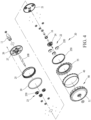
FIG. 3 is an exploded view showing components and configurations of a first speed-change assembly of the present invention. -
FIG. 4 is an exploded view, taken from a different angle, showing the components and configurations of the first speed-change assembly of the present invention. -
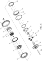
FIG. 5 is an exploded view showing components and configurations of a second speed-change assembly of the present invention. -
FIG. 6 is an exploded view, taken from a different angle, showing the components and configurations of the second speed-change assembly of the present invention. -
FIG. 7 is a cross-sectional view of present invention, taken from line A-A ofFIG. 2 . -
FIG. 8 is a cross-sectional view of present invention, taken from line B-B ofFIG. 2 . -
FIG. 9 is a cross-sectional view of present invention, taken from line C-C ofFIG. 2 . -
FIG. 10 is a cross-sectional view of present invention, taken from line D-D ofFIG. 2 . - A two-stage speed-change output device according to the present invention is constructed as shown in
FIGS. 1 and2 , and comprises amain axle 100, amotor assembly 10, a first speed-change assembly 20, a second speed-change assembly 30, and anoutput shell 40. Themotor assembly 10 is operable to drive and rotate the first speed-change assembly 20 in a reverse or backward direction and to drive and rotate the second speed-change assembly 30 in a forward direction to allow the first and second speed-change assemblies output shell 40 in the same direction, so that the two-stage speed-change output device may carry out switching for two-stage speed change by using the forward and backward rotations of themotor assembly 10. - With regards to a detailed structure of the two-stage speed-change output device, reference is made to
FIGS. 2 and5 . Themotor assembly 10 includes amain axle 100 on which aninput sleeve 11 is rotatably mounted by means of a plurality of bearings. Anelectromagnetic mechanism 12 is mounted to an end of theinput sleeve 11, so that theelectromagnetic mechanism 12, when electrified and energized, and thus excited, drives theinput sleeve 11 to rotate forward and backward relative to themain axle 100. Further, themotor assembly 10 comprises anexternal motor housing 13 mounted on themain axle 100 at an outer side of theelectromagnetic mechanism 12, and themotor assembly 10 comprises aninternal motor housing 14 arranged at an inner side of theelectromagnetic mechanism 12 to be combined with theexternal motor housing 13, wherein anaxle seat 15, which is rotatably mounted on theinput sleeve 11, is fit in and mounted to a center of theinternal motor housing 14, so that theinput sleeve 11 extends through and projects out of theinternal motor housing 14 to drive the first and second speed-change assemblies - As shown in
FIGS. 2 ,3 , and4 , the first speed-change assembly 20 is arranged between themain axle 100 and a corresponding end of theinput sleeve 11 that extends out of themotor assembly 10. The first speed-change assembly 20 comprises afirst carrier frame 21 that is fixed to the end of theinput sleeve 11 by asleeve fastener 16. Thefirst carrier frame 21 has two opposite surfaces on which afirst planet group 22 and asecond planet group 23 are respectively arranged. The first andsecond planet groups first planets 220 andsecond planets 230 of the same contour. The first andsecond planets second planets first carrier frame 21. Further, afirst sun gear 24 is fixed on themain axle 100 and in mating engagement with each of thefirst planets 220 of the first planet group 22 (as shown inFIG. 7 ). Afirst shell 25 is rotatably mounted on an outer circumference of thefirst carrier frame 21 by means of bead groups on two sides thereof. One side of thefirst shell 25 that is opposite to the second speed-change assembly 30 is provided with ashell cover 250 fastened thereto for constraining or positioning the bead groups, and on a surface of an opposite side of thefirst shell 25, atransmission wheel disc 26 that is rotatably mounted on theinput sleeve 11 is fixed . Thetransmission wheel disc 26 is provided, on a center thereof, with asecond sun gear 27 and athird sun gear 28 that are respectively arranged on two opposite sides thereof, wherein thesecond sun gear 27 of thetransmission wheel disc 26 is in mating engagement with each of thesecond planets 230 of the second planet group 23 (as shown inFIG. 8 ). Thethird sun gear 28 of thetransmission wheel disc 26 is connected with the second speed-change assembly 30, so that an input power that is input through theinput sleeve 11 is transmitted through the first speed-change assembly 20 to the second speed-change assembly 30. A first one-way clutching element 29 is fit on an outer circumference of the first shell 25 (as shown inFIG. 7 ). The first one-way clutching element 29 is operable in either the forward direction or the backward direction, and in the present invention, a primary example for implementing the first one-way clutching element 29 is operating in the forward direction and idling in the backward direction. Theoutput shell 40 is fit on an outer circumference of the first one-way clutching element 29, so that the input power is transmitted through theinput sleeve 11, the first andsecond planet groups first carrier frame 21, thetransmission wheel disc 26, thefirst shell 25, and the first one-way clutching element 29 to be outputted through theoutput shell 40. - As shown in
FIGS. 2 ,5 , and6 , the second speed-change assembly 30 is arranged between the first speed-change assembly 20 and themotor assembly 10. The second speed-change assembly 30 comprises asecond carrier frame 31 that is mounted on theaxle seat 15 of themotor assembly 10. Athird planet group 32 is arranged on a surface of thesecond carrier frame 31 that corresponds to the first speed-change assembly 20, and thethird planet group 32 comprises a plurality ofthird planets 320 that are of the same contour. Each of thethird planets 320 of thethird planet group 32 is in mating engagement with thethird sun gear 28 of thetransmission wheel disc 26 of the first speed-change assembly 20, so that thetransmission wheel disc 26 drives each of thethird planets 320 of thethird planet group 32 to rotate. Further, asecond shell 33 is rotatably mounted on an outer circumference of thesecond carrier frame 31 by means of bead groups on two sides thereof. One side of thesecond carrier frame 31 that is opposite to the first speed-change assembly 20 is provided with ashell cover 330 fastened thereto for constraining or positioning the bead groups, and thesecond shell 33 is provided, on an inner circumference thereof, with an internalring toothed section 331 that is in mating engagement with an outer circumferential of each of the third planets 320 (as shown inFIG. 10 ), so that thethird planet group 32 drives, by means of each of thethird planets 320, thesecond shell 33. Further, a second one-way clutching element 34 is fit to an outer circumference of thesecond shell 33, and the second one-way clutching element 34 is a one-way clutching element that is operable in the same direction as the above-mentioned first one-way clutching element 29. An outer circumference of the second one-way clutching element 34 is joined with theoutput shell 40, so that the input power is transmitted through theinput sleeve 11, the first andsecond planet groups first carrier frame 21, thetransmission wheel disc 26, thethird planet group 32 of thesecond carrier frame 31, thesecond shell 33, and the second one-way clutching element 34 to output through theoutput shell 40. According to some embodiments, a third one-way clutching element 35 is arranged between thesecond carrier frame 31 of the second speed-change assembly 30 and theinternal motor housing 14 of themotor assembly 10, and the third one-way clutching element 35 is a one-way clutching element that is operable in the same direction as the above-mentioned first and second one-way clutching elements output shell 40, the second speed-change assembly 30 is in idling rotation with respect to themotor assembly 10 so as not to affect internal components thereof. - According to some embodiments, as shown in
FIGS. 2-6 , the two-stage speed-change output device according to the present invention is applicable to awheel hub assembly 50 of an electric vehicle. Thewheel hub assembly 50 comprises a firstwheel hub shell 51, a secondwheel hub shell 52, and an internalwheel hub shell 55. Fasteners are applied to fix, in sequence, outer flanges or rims of the firstwheel hub shell 51, theoutput shell 40, the internalwheel hub shell 55, and the secondwheel hub shell 52, wherein the firstwheel hub shell 51 is rotatably mounted, at a center thereof, on themain axle 100, and the internalwheel hub shell 55 is rotatably mounted, on an inner circumference thereof, on an outer circumference of theinternal motor housing 14 of themotor assembly 10 by means of bead groups on two sides thereof. One side of the internalwheel hub shell 55 that is opposite to the second speed-change assembly 30 is provided with awheel hub cover 56 fastened thereto for constraining or positioning the bead groups. Further, outer flanges of the firstwheel hub shell 51 and the secondwheel hub shell 52 are provided for connecting a plurality of spokes (not shown) of the vehicle wheel rim, so that the two-stage speed-change output device according to the present invention may be applied to drive a wheel of the electric vehicle and also to conduct switching or changing of speed at the same time. - Further, the first and second speed-change assemblies 20, 30 may fulfill increase or decrease of speed by means of gear ratios between the
first planet group 22, thesecond planet group 23, and thethird planet group 32 with respect to thefirst sun gear 24, thesecond sun gear 27, and thethird sun gear 28 respectively. For example, the first speed-change assembly 20 may be assumed for a high-speed operation, while the second speed-change assembly 30 is set for a mode of low-speed operation, or alternatively, the first speed-change assembly 20 is set for low-speed operation, while the second speed-change assembly 30 assumes a mode for high-speed operation. - In this way, the two-stage speed-change output device that features a small amount of occupied space and exhibiting same direction output and speed changing is constructed.
- In a practical operation of the two-stage speed-change output device according to the present invention as being applied to the
wheel hub assembly 50 of the electric vehicle, as shown inFIG. 2 , the counterclockwise direction is taken as the backward or reverse direction, while the clockwise direction is set as the forward direction. Observing in a direction from the right side, when themotor assembly 10 drives theinput sleeve 11 in the backward direction, theinput sleeve 11 simultaneously drives thefirst carrier frame 21 of the first speed-change assembly 20 to rotate in the backward direction. Since thefirst sun gear 24 is fixed, in an immobile manner, on themain axle 100, thefirst planet group 22 of thefirst carrier frame 21 rotates (orbits) around thefirst sun gear 24 in the backward direction, and each of thefirst planets 220 rotates (spins) synchronously in the backward direction (as shown inFIG. 7 ). Since each individual one of thefirst planets 220 of thefirst planet group 22 and each corresponding one of thesecond planets 230 of thesecond planet group 23 are fixed together, thesecond planet group 23 and each of thesecond planets 230 are also forced to rotate (orbit) in the backward direction and rotating (spinning) in the backward direction, so that each of thesecond planets 230 of thesecond planet group 23 synchronously drives thesecond sun gear 27 of thetransmission wheel disc 26 that is rotatably mounted on theinput sleeve 11 to rotate in the forward direction (as shown inFIG. 8 ), thereby making thetransmission wheel disc 26 synchronously drive thefirst shell 25 that is fit to the outer circumference of thefirst carrier frame 21 to rotate in the forward direction. Since the first one-way clutching element 29 mounted on thefirst shell 25 is operating in the forward direction, thefirst shell 25 drives, by means of the first one-way clutching element 29, theoutput shell 40 to do outputting in the forward direction (as shown inFIG. 9 ). Further, since the first and secondwheel hub shells wheel hub shell 55 of thewheel hub assembly 50 are fastened to theoutput shell 40, the purpose of driving the wheel of the electric vehicle to rotate can be achieved by means of driving thewheel hub assembly 50. Also, thetransmission wheel disc 26 that is caused to rotate in the forward direction makes thethird sun gear 28 arranged thereon to synchronously rotate in the forward direction, so that each of thethird planets 320 of thethird planet group 32 that is in mating engagement with thethird sun gear 28 is caused to synchronously rotate (spin) in the backward direction. Since each of thethird planets 320 of thethird planet group 32 is in mating engagement with the internal ringtoothed section 331 of thesecond shell 33 of the second speed-change assembly 30, a power is developed for intending to drive thesecond carrier frame 31 of thethird planet group 32 to rotate in the forward direction, yet due to thesecond carrier frame 31 being fit to theinternal motor housing 14 of themotor assembly 10 by means of the third one-way clutching element 35 that is operable in the forward direction (and thus becoming fixed in this case), thesecond carrier frame 31 is kept fixed by theinternal motor housing 14 in an immobile condition, so that each of thethird planets 320 of thethird planet group 32 is rotating in the backward direction and synchronously driving thesecond shell 33 to rotate in the backward direction (as shown inFIG. 10 ). Since the second one-way clutching element 34 that is mounted to thesecond shell 33 is operable in the forward direction, thesecond shell 33 rotating in the backward direction become freewheeling or idle-rotating with respect to theoutput shell 40 by means of the second one-way clutching element 34. Thus, when themotor assembly 10 drives theinput sleeve 11 to rotate in the backward direction, it is only the first speed-change assembly 20 that drives theoutput shell 40, while the second speed-change assembly 30 is set in an idling, and thus non-driving, condition. - When the
motor assembly 10 drives theinput sleeve 11 to rotate in the forward direction, theinput sleeve 11 synchronously drives thefirst carrier frame 21 of the first speed-change assembly 20 to rotate in the forward direction. Since thefirst sun gear 24 is fixed, in an immobile condition, on themain axle 100, thefirst planet group 22 of thefirst carrier frame 21 is caused to rotate (orbit) around thefirst sun gear 24 in the forward direction, and each of thefirst planets 220 synchronously rotates (spins) in the forward direction. Since each individual one of thefirst planets 220 of thefirst planet group 22 and each corresponding one of thesecond planets 230 of thesecond planet group 23 are fixed together, thesecond planet group 23 and each of thesecond planets 230 are also caused to orbit in the forward direction and spinning in the forward direction, so that each of thesecond planets 230 of thesecond planet group 23 synchronously drives thesecond sun gear 27 of thetransmission wheel disc 26 that is rotatably mounted on theinput sleeve 11 to rotate in the backward direction, making thetransmission wheel disc 26 synchronously drive thefirst shell 25 that is rotatably fit to the outer circumference of thefirst carrier frame 21 to rotate in the backward direction. Since the first one-way clutching element 29 that is fit to thefirst shell 25 is operable in the forward direction, thefirst shell 25 rotating in the backward direction becomes freewheeling or idle-rotating with respect to theoutput shell 40 by means of the first one-way clutching element 29. Also, thethird sun gear 28 that is arranged on thetransmission wheel disc 26 that is rotating in the backward direction is caused to synchronously rotate in the backward direction, so that each of thethird planets 320 of thethird planet group 32 that is in mating engagement with thethird sun gear 28 is caused to synchronously rotate (spin) in the forward direction. Since each individual one of thethird planets 320 of thethird planet group 32 is in mating engagement with the internal ringtoothed section 33 of thesecond shell 331 of the second speed-change assembly 30, assuming a power-outputting condition, so as to drive thesecond carrier frame 31 on which thethird planet group 32 is arranged to rotate in the forward direction. However, since thesecond carrier frame 31 is fit to theinternal motor housing 14 of themotor assembly 10 by means of the third one-way clutching element 35 that is operable in the forward direction (and thus becoming fixed in this case), thesecond carrier frame 31 is kept fixed by theinternal motor housing 14 in an immobile condition, so that each of thethird planets 320 of thethird planet group 32 synchronously drives thesecond shell 33 to rotate in the forward direction. Since the second one-way clutching element 34 that is mounted to thesecond shell 33 is operable in the forward direction, thesecond shell 33 rotating in the forward direction drives, by means of the second one-way clutching element 34, theoutput shell 40 to rotate and output in the forward direction. Further, since the first and secondwheel hub shells wheel hub shell 55 of thewheel hub assembly 50 and theoutput shell 40 are fastened together, the purpose of driving the wheel of the electric vehicle to rotate can be achieved by means of driving thewheel hub assembly 50. Thus, when themotor assembly 10 drives theinput sleeve 11 to rotate in the forward direction, it is only the second speed-change assembly 30 that drives theoutput shell 40, while the first speed-change assembly 20 is set in an idling, and thus non-driving, condition. - When the electric vehicle is backed up and moving reversely, as shown in
FIGS. 2 and7-10 , the wheel is caused by a frictional force thereof with respect to a road surface to force thewheel hub assembly 50 to rotate in the backward direction, and therefore, the first and secondwheel hub shells wheel hub assembly 50 drives theoutput shell 40 to rotate in the backward direction. Since the first and second one-way clutching elements 29, 34 of the first and second speed-change assemblies 20, 30 that are mounted to an inner circumference of the output shell 40 are both a one-way clutching element that is of an arrangement that, considering transmission in a direction from inside toward outside, is operable in the forward direction and idling in the backward direction, so that when the output shell 40 rotates backward, as being transmitted reversely from outside to inside, the first and second one-way clutching elements 29, 34 oppositely drive, in the backward direction, the first shell 25 of the first speed-change assembly 20 and the second shell 33 of the second speed-change assembly 30 respectively corresponding thereto to rotate in the backward direction, wherein the first shell 25 of the first speed-change assembly 20 that rotates in the backward direction synchronously drives the transmission wheel disc 26 and thus the third sun gear 28 to rotate in the backward direction, therefore driving each of the third planets 320 of the third planet group 32 in mating engagement therewith to rotate (spin) in the forward direction; and the second shell 33 of the second speed-change assembly 30 that is also rotating in the backward direction drives each of the third planets 320 of the third planet group 32 in mating engagement with the internal ring toothed section 331 thereof to rotate (spin) in the backward direction, and therefore, a situation of immobility is developed due to the operations of the two are in opposite directions, this making it impossible for the electric vehicle to back up. Since each of thethird planets 320 of thethird planet group 32 is mounted on thesecond carrier frame 31 and since thesecond carrier frame 31 is fit to theinternal motor housing 14 of themotor assembly 10 by means of the third one-way clutching element 35, so that thesecond carrier frame 31 is set in a fixed, immobile condition in the forward direction, yet freewheeling or idle-rotating in the backward direction. This makes thesecond carrier frame 31 unidirectionally rotatable, and not affected by thethird planets 320 of thethird planet group 32 being fixed, and thus, driving through two-stage speed-change output of power is achievable and the electric vehicle is allowed to back up. - By means of the arrangement and description provided above, the
motor assembly 10 of the two-stage speed-change output device according to the present invention may make use of rotation in either the backward direction or the forward direction to respectively drive the first and second speed-change assemblies change assemblies way clutching elements output shell 40 in the same direction, allowing the two-stage speed-change output device of the present invention to be operable for switching with two stages of speed change by using the forward and backward rotations of themotor assembly 10, exhibiting advantages of being easy to operate, occupying a relatively small amount of space, and being applicable to driving and speed changing for a small-sized electric vehicle, and thus practical utilization thereof can be greatly enhanced.
Claims (8)
- A two-stage speed-change output device, comprising a main axle (100), and a motor assembly (10), a first speed-change assembly (20), and a second speed-change assembly (30) mounted on the main axle (100), the first speed-change assembly (20) and the second speed-change assembly (30) being mounted inside an output shell (40) by means of a first one-way clutching element (29) and a second one-way clutching element (34) that are operable in a forward direction, wherein the motor assembly (10) is operable to rotate in a backward direction to drive the first one-way clutching element (29) of the first speed-change assembly (20) to drive the output shell (40) to rotate in the forward direction and to drive the second one-way clutching element (34) of the second speed-change assembly (30) to idle with respect to the output shell (40), and the motor assembly (10) is also operable to rotate in the forward direction to drive the second one-way clutching element (34) of the second speed-change assembly (30) to drive the output shell (40) to rotate in the forward direction and to drive the first one-way clutching element (29) of the first speed-change assembly (20) to idle with respect to the output shell (40), wherein the two-stage speed-change output device is operable to switch for two-stage speed change in driving the output shell (40) in a same direction with rotations of the motor assembly (10) in the forward and backward directions.
- The two-stage speed-change output device according to claim 1, wherein the motor assembly (10) comprises an input sleeve (11) rotatably mounted on the main axle (100), an electromagnetic mechanism (12) that is excitable through energization being mounted on one end of the input sleeve (11), wherein the input sleeve (11) is driven, by means of the electromagnetic mechanism (12) being energized and excited, to rotate in one of the forward direction and backward direction relative to the main axle (100), and wherein the motor assembly (10) comprises an external motor housing (13) arranged on the main axle (100) at an outer side of the electromagnetic mechanism (12), and the motor assembly (10) further comprises an internal motor housing (14) that is arranged at an inner side of the electromagnetic mechanism (12) and is combined with the external motor housing (13), an axle seat (15) being fit in a center of the internal motor housing (14) and rotatably mounted on the input sleeve (11).
- The two-stage speed-change output device according to claim 2, wherein the first speed-change assembly (20) comprises a first carrier frame (21) fixedly mounted on the input sleeve (11), the first carrier frame (21) having two surfaces on which a first planet group (22) and a second planet group (23) are respectively arranged, the first and second planet groups (22, 23) respectively comprising a plurality of first planets (220) and second planets (230) that are of same contours and are rotatably mounted on the first carrier frame (21) and synchronously in a same direction, the first planet group (22) further comprising a first sun gear (24) that is fixedly mounted on the main axle (100) and in mating engagement with each of the first planets (220), a first shell (25) being rotatably mounted to an outer circumference of the first carrier frame (21), the first one-way clutching element (29) being fixed to an outer circumference of the first shell (25), a transmission wheel disc (26) being fixedly mounted to the first shell (25) and rotatably mounted on the input sleeve (11), a second sun gear (27) and a third sun gear (28) being respectively formed on two surfaces of the transmission wheel disc (26) at a center thereof, wherein the second sun gear (27) is in mating engagement with each of the second planets (230) of the second planet group (23), and the third sun gear (28) is connected to and drives the second speed-change assembly (30).
- The two-stage speed-change output device according to claim 3, wherein the second speed-change assembly (30) is arranged between the first speed-change assembly (20) and the motor assembly (10), and the second speed-change assembly (30) comprises a second carrier frame (31) mounted to the axle seat (15) of the motor assembly (10), a third planet group (32) being arranged on a surface of the second carrier frame (31) that corresponds to the first speed-change assembly (20), the third planet group (32) comprising a plurality of third planets (320) that are of a same contour and are rotatably mounted on the second carrier frame (31), each of the third planets (320) being in mating engagement with the third sun gear (28) of the transmission wheel disc (26) of the first speed-change assembly (20), a second shell (33) being rotatably mounted to an outer circumference of the second carrier frame (31), an internal ring toothed section (331) being arranged on an inner circumference of the second shell (33) and in mating engagement with an outer circumference of each of the third planets (320), the second one-way clutching element (34) being fixedly mounted on an outer circumference of the second shell (33).
- The two-stage speed-change output device according to claim 4, wherein a third one-way clutching element (35) is arranged between the second speed-change assembly (30) and the internal motor housing (14) of the motor assembly (10), and the third one-way clutching element (35) and the first and second one-way clutching elements (29, 34) are one-way clutching elements that are operable in a same direction, wherein when an input power is inputted reversely from the output shell (40), the second speed-change assembly (30) is idling with respect to the motor assembly (10).
- The two-stage speed-change output device according to claim 4, wherein the first and second speed-change assemblies (20, 30) are operable for increasing or decreasing speed by using gear ratios between the first planet group (22), the second planet group (23), and the third planet group (32) with respect to the first sun gear (24), the second sun gear (27), and the third sun gear (28) corresponding thereto.
- A wheel hub assembly of an electric vehicle, the wheel hub assembly (50) comprising the two-stage speed-change output device according to one of claims 1-6, the two-stage speed-change output device being operable to drive the wheel hub assembly (50) and simultaneously conduct switching for speed change.
- The wheel hub assembly of the electric vehicle according to claim 7, wherein the wheel hub assembly (50) comprises a first wheel hub shell (51), a second wheel hub shell (52), and an internal wheel hub shell (55), which are fastened together by means of at least one fastener, at least one of the first wheel hub shell (51), the internal wheel hub shell (55), and the second wheel hub shell (52) being fastened to the output shell (40), and wherein the first wheel hub shell (51) is rotatably mounted, at a center thereof, on the main axle (100), and the internal wheel hub shell (55) is rotatably mounted on an outer circumference of the internal motor housing (14) of the motor assembly (10).
Applications Claiming Priority (1)
| Application Number | Priority Date | Filing Date | Title |
|---|---|---|---|
| TW110142642A TWI889935B (en) | 2021-11-16 | 2021-11-16 | Two-stage speed-variable output device and a wheel hub set of an electric vehicle using it |
Publications (1)
| Publication Number | Publication Date |
|---|---|
| EP4180692A1 true EP4180692A1 (en) | 2023-05-17 |
Family
ID=84331411
Family Applications (1)
| Application Number | Title | Priority Date | Filing Date |
|---|---|---|---|
| EP22206567.4A Pending EP4180692A1 (en) | 2021-11-16 | 2022-11-10 | Two-stage speed-change output device and electric vehicle using same |
Country Status (5)
| Country | Link |
|---|---|
| US (1) | US12304302B2 (en) |
| EP (1) | EP4180692A1 (en) |
| JP (2) | JP7554491B2 (en) |
| CN (2) | CN116135684A (en) |
| TW (1) | TWI889935B (en) |
Families Citing this family (2)
| Publication number | Priority date | Publication date | Assignee | Title |
|---|---|---|---|---|
| TWI889935B (en) * | 2021-11-16 | 2025-07-11 | 姚立和 | Two-stage speed-variable output device and a wheel hub set of an electric vehicle using it |
| CN120716456A (en) * | 2024-03-28 | 2025-09-30 | 加特可株式会社 | Drive device and vehicle |
Citations (5)
| Publication number | Priority date | Publication date | Assignee | Title |
|---|---|---|---|---|
| US7628727B2 (en) * | 2006-02-16 | 2009-12-08 | Smc Kabushiki Kaisha | Automatic speed reducing ratio-switching apparatus |
| EP2444312A1 (en) * | 2010-10-25 | 2012-04-25 | Sun Race Sturmey-Archer Inc. | Speed changing apparatus |
| CN101997361B (en) * | 2009-08-10 | 2014-05-14 | 日驰企业股份有限公司 | Motor speed change mechanism |
| CN209616873U (en) * | 2018-12-28 | 2019-11-12 | 樊朝晖 | A kind of positive and negative unidirectional coaxial two stage speed change wheel apparatus |
| US20220135179A1 (en) * | 2019-02-28 | 2022-05-05 | Amotech Co., Ltd. | Hub type driving device and electric bicycle using same |
Family Cites Families (12)
| Publication number | Priority date | Publication date | Assignee | Title |
|---|---|---|---|---|
| US6387008B1 (en) * | 1999-09-13 | 2002-05-14 | Industrial Technology Research Institute | Speed-changing control mechanism of multistage speed-changing wheel hub |
| TWI460364B (en) * | 2009-05-27 | 2014-11-11 | Sun Race Sturmey Archer Inc | Speed changing apparatus for motors |
| US8622865B2 (en) * | 2009-05-27 | 2014-01-07 | Sun Race Sturmey-Archer, Inc. | Speed change mechanism |
| TWI414454B (en) * | 2011-03-11 | 2013-11-11 | Chiu Hsiang Lo | Electric wheel hub motor |
| US8348798B2 (en) * | 2010-10-01 | 2013-01-08 | Chiu-Hsiang Lo | Hub motor for electric vehicles |
| JP5821371B2 (en) * | 2011-08-02 | 2015-11-24 | 日本精工株式会社 | In-wheel motor |
| TWM426686U (en) * | 2011-09-20 | 2012-04-11 | Hwa Kai Entpr Co Ltd De | Planetary gearbox structure |
| WO2015050424A1 (en) * | 2013-10-03 | 2015-04-09 | Servando Soto Velasco | Planetary gear system having various power-transmission configurations |
| CN109469714B (en) * | 2017-09-08 | 2023-11-14 | 广州市新域动力技术有限公司 | Two-gear automatic speed-changing electric driving wheel assembly |
| JP6978549B1 (en) * | 2020-06-23 | 2021-12-08 | 華邦電子股▲ふん▼有限公司Winbond Electronics Corp. | Input receiver |
| TWI889935B (en) * | 2021-11-16 | 2025-07-11 | 姚立和 | Two-stage speed-variable output device and a wheel hub set of an electric vehicle using it |
| TWM631683U (en) * | 2021-11-16 | 2022-09-11 | 姚立和 | Two-stage variable speed output device and electric vehicle hub assembly using the same |
-
2021
- 2021-11-16 TW TW110142642A patent/TWI889935B/en active
-
2022
- 2022-11-03 CN CN202211368988.8A patent/CN116135684A/en active Pending
- 2022-11-03 CN CN202222973697.3U patent/CN219406786U/en active Active
- 2022-11-10 JP JP2022180614A patent/JP7554491B2/en active Active
- 2022-11-10 EP EP22206567.4A patent/EP4180692A1/en active Pending
- 2022-11-10 US US17/984,268 patent/US12304302B2/en active Active
- 2022-11-10 JP JP2022003734U patent/JP3240489U/en not_active Ceased
Patent Citations (5)
| Publication number | Priority date | Publication date | Assignee | Title |
|---|---|---|---|---|
| US7628727B2 (en) * | 2006-02-16 | 2009-12-08 | Smc Kabushiki Kaisha | Automatic speed reducing ratio-switching apparatus |
| CN101997361B (en) * | 2009-08-10 | 2014-05-14 | 日驰企业股份有限公司 | Motor speed change mechanism |
| EP2444312A1 (en) * | 2010-10-25 | 2012-04-25 | Sun Race Sturmey-Archer Inc. | Speed changing apparatus |
| CN209616873U (en) * | 2018-12-28 | 2019-11-12 | 樊朝晖 | A kind of positive and negative unidirectional coaxial two stage speed change wheel apparatus |
| US20220135179A1 (en) * | 2019-02-28 | 2022-05-05 | Amotech Co., Ltd. | Hub type driving device and electric bicycle using same |
Also Published As
| Publication number | Publication date |
|---|---|
| TWI889935B (en) | 2025-07-11 |
| CN116135684A (en) | 2023-05-19 |
| US12304302B2 (en) | 2025-05-20 |
| US20230150355A1 (en) | 2023-05-18 |
| JP3240489U (en) | 2023-01-12 |
| TW202321104A (en) | 2023-06-01 |
| CN219406786U (en) | 2023-07-25 |
| JP2023073994A (en) | 2023-05-26 |
| JP7554491B2 (en) | 2024-09-20 |
Similar Documents
| Publication | Publication Date | Title |
|---|---|---|
| JP4513492B2 (en) | Differential device and vehicle driving force transmission unit using the same | |
| EP2204316B1 (en) | Drive system for driving a vehicle wheel | |
| US12304302B2 (en) | Two-stage speed-change output device and electric vehicle using same | |
| US20120305325A1 (en) | Electric power-assisted bicycle | |
| US6007447A (en) | Transmission unit for the disk motor of an electromotive bicycle | |
| US7780563B2 (en) | Drive force distribution apparatus | |
| US20190120357A1 (en) | Apparatus for power train, vehicle including the same and control method for the same | |
| US20190118649A1 (en) | Power train system, vehicle including the same and control method thereof | |
| JP2009061923A (en) | Hybrid vehicle drive system | |
| US20190120356A1 (en) | Apparatus for power train, vehicle including the same and control method for the same | |
| US11428304B2 (en) | Torque vectoring device | |
| NO349294B1 (en) | Pedally propelled vehicle drive system | |
| US10525827B2 (en) | Control method of power train system | |
| US20190120374A1 (en) | Control method for power train apparatus | |
| WO2018224921A1 (en) | A vehicle | |
| CN119078480A (en) | A three-motor integrated electric drive axle structure and control method | |
| US20190118648A1 (en) | Apparatus for power train and vehicle including the same | |
| US12110950B1 (en) | Compact two-speed transmission with compound planetary stage | |
| KR102654790B1 (en) | SINGLE SHAFT DRIVE FOR ELECTRIC Mobility | |
| JP7686550B2 (en) | Drive unit | |
| TW202615294A (en) | Pedally propelled vehicle drive system | |
| TW202615293A (en) | Pedally propelled vehicle drive system | |
| WO2025204200A1 (en) | Transmission device and vehicle | |
| JP2021115944A (en) | Power division mechanism | |
| JP6888432B2 (en) | Hybrid vehicle drive |
Legal Events
| Date | Code | Title | Description |
|---|---|---|---|
| PUAI | Public reference made under article 153(3) epc to a published international application that has entered the european phase |
Free format text: ORIGINAL CODE: 0009012 |
|
| STAA | Information on the status of an ep patent application or granted ep patent |
Free format text: STATUS: REQUEST FOR EXAMINATION WAS MADE |
|
| 17P | Request for examination filed |
Effective date: 20230315 |
|
| AK | Designated contracting states |
Kind code of ref document: A1 Designated state(s): AL AT BE BG CH CY CZ DE DK EE ES FI FR GB GR HR HU IE IS IT LI LT LU LV MC ME MK MT NL NO PL PT RO RS SE SI SK SM TR |
|
| STAA | Information on the status of an ep patent application or granted ep patent |
Free format text: STATUS: EXAMINATION IS IN PROGRESS |
|
| 17Q | First examination report despatched |
Effective date: 20250324 |