EP4180609A1 - Motor vehicle - Google Patents
Motor vehicle Download PDFInfo
- Publication number
- EP4180609A1 EP4180609A1 EP22206600.3A EP22206600A EP4180609A1 EP 4180609 A1 EP4180609 A1 EP 4180609A1 EP 22206600 A EP22206600 A EP 22206600A EP 4180609 A1 EP4180609 A1 EP 4180609A1
- Authority
- EP
- European Patent Office
- Prior art keywords
- door
- motor vehicle
- configuration
- motor
- closed configuration
- Prior art date
- Legal status (The legal status is an assumption and is not a legal conclusion. Google has not performed a legal analysis and makes no representation as to the accuracy of the status listed.)
- Granted
Links
Images


Classifications
-
- E—FIXED CONSTRUCTIONS
- E05—LOCKS; KEYS; WINDOW OR DOOR FITTINGS; SAFES
- E05F—DEVICES FOR MOVING WINGS INTO OPEN OR CLOSED POSITION; CHECKS FOR WINGS; WING FITTINGS NOT OTHERWISE PROVIDED FOR, CONCERNED WITH THE FUNCTIONING OF THE WING
- E05F15/00—Power-operated mechanisms for wings
- E05F15/70—Power-operated mechanisms for wings with automatic actuation
- E05F15/73—Power-operated mechanisms for wings with automatic actuation responsive to movement or presence of persons or objects
- E05F15/75—Power-operated mechanisms for wings with automatic actuation responsive to movement or presence of persons or objects responsive to the weight or other physical contact of a person or object
-
- E—FIXED CONSTRUCTIONS
- E05—LOCKS; KEYS; WINDOW OR DOOR FITTINGS; SAFES
- E05B—LOCKS; ACCESSORIES THEREFOR; HANDCUFFS
- E05B85/00—Details of vehicle locks not provided for in groups E05B77/00 - E05B83/00
-
- E—FIXED CONSTRUCTIONS
- E05—LOCKS; KEYS; WINDOW OR DOOR FITTINGS; SAFES
- E05F—DEVICES FOR MOVING WINGS INTO OPEN OR CLOSED POSITION; CHECKS FOR WINGS; WING FITTINGS NOT OTHERWISE PROVIDED FOR, CONCERNED WITH THE FUNCTIONING OF THE WING
- E05F15/00—Power-operated mechanisms for wings
- E05F15/60—Power-operated mechanisms for wings using electrical actuators
- E05F15/603—Power-operated mechanisms for wings using electrical actuators using rotary electromotors
- E05F15/611—Power-operated mechanisms for wings using electrical actuators using rotary electromotors for swinging wings
- E05F15/616—Power-operated mechanisms for wings using electrical actuators using rotary electromotors for swinging wings operated by push-pull mechanisms
-
- B—PERFORMING OPERATIONS; TRANSPORTING
- B60—VEHICLES IN GENERAL
- B60R—VEHICLES, VEHICLE FITTINGS, OR VEHICLE PARTS, NOT OTHERWISE PROVIDED FOR
- B60R25/00—Fittings or systems for preventing or indicating unauthorised use or theft of vehicles
- B60R25/20—Means to switch the anti-theft system on or off
- B60R25/24—Means to switch the anti-theft system on or off using electronic identifiers containing a code not memorised by the user
-
- E—FIXED CONSTRUCTIONS
- E05—LOCKS; KEYS; WINDOW OR DOOR FITTINGS; SAFES
- E05B—LOCKS; ACCESSORIES THEREFOR; HANDCUFFS
- E05B81/00—Power-actuated vehicle locks
- E05B81/02—Power-actuated vehicle locks characterised by the type of actuators used
- E05B81/04—Electrical
- E05B81/06—Electrical using rotary motors
-
- E—FIXED CONSTRUCTIONS
- E05—LOCKS; KEYS; WINDOW OR DOOR FITTINGS; SAFES
- E05B—LOCKS; ACCESSORIES THEREFOR; HANDCUFFS
- E05B81/00—Power-actuated vehicle locks
- E05B81/24—Power-actuated vehicle locks characterised by constructional features of the actuator or the power transmission
- E05B81/32—Details of the actuator transmission
-
- E—FIXED CONSTRUCTIONS
- E05—LOCKS; KEYS; WINDOW OR DOOR FITTINGS; SAFES
- E05F—DEVICES FOR MOVING WINGS INTO OPEN OR CLOSED POSITION; CHECKS FOR WINGS; WING FITTINGS NOT OTHERWISE PROVIDED FOR, CONCERNED WITH THE FUNCTIONING OF THE WING
- E05F15/00—Power-operated mechanisms for wings
- E05F15/60—Power-operated mechanisms for wings using electrical actuators
-
- E—FIXED CONSTRUCTIONS
- E05—LOCKS; KEYS; WINDOW OR DOOR FITTINGS; SAFES
- E05F—DEVICES FOR MOVING WINGS INTO OPEN OR CLOSED POSITION; CHECKS FOR WINGS; WING FITTINGS NOT OTHERWISE PROVIDED FOR, CONCERNED WITH THE FUNCTIONING OF THE WING
- E05F15/00—Power-operated mechanisms for wings
- E05F15/70—Power-operated mechanisms for wings with automatic actuation
- E05F15/77—Power-operated mechanisms for wings with automatic actuation using wireless control
-
- E—FIXED CONSTRUCTIONS
- E05—LOCKS; KEYS; WINDOW OR DOOR FITTINGS; SAFES
- E05B—LOCKS; ACCESSORIES THEREFOR; HANDCUFFS
- E05B85/00—Details of vehicle locks not provided for in groups E05B77/00 - E05B83/00
- E05B85/10—Handles
- E05B85/103—Handles creating a completely closed wing surface
-
- E—FIXED CONSTRUCTIONS
- E05—LOCKS; KEYS; WINDOW OR DOOR FITTINGS; SAFES
- E05Y—INDEXING SCHEME ASSOCIATED WITH SUBCLASSES E05D AND E05F, RELATING TO CONSTRUCTION ELEMENTS, ELECTRIC CONTROL, POWER SUPPLY, POWER SIGNAL OR TRANSMISSION, USER INTERFACES, MOUNTING OR COUPLING, DETAILS, ACCESSORIES, AUXILIARY OPERATIONS NOT OTHERWISE PROVIDED FOR, APPLICATION THEREOF
- E05Y2201/00—Constructional elements; Accessories therefor
- E05Y2201/40—Motors; Magnets; Springs; Weights; Accessories therefor
- E05Y2201/404—Function thereof
- E05Y2201/422—Function thereof for opening
- E05Y2201/426—Function thereof for opening for the initial opening movement
-
- E—FIXED CONSTRUCTIONS
- E05—LOCKS; KEYS; WINDOW OR DOOR FITTINGS; SAFES
- E05Y—INDEXING SCHEME ASSOCIATED WITH SUBCLASSES E05D AND E05F, RELATING TO CONSTRUCTION ELEMENTS, ELECTRIC CONTROL, POWER SUPPLY, POWER SIGNAL OR TRANSMISSION, USER INTERFACES, MOUNTING OR COUPLING, DETAILS, ACCESSORIES, AUXILIARY OPERATIONS NOT OTHERWISE PROVIDED FOR, APPLICATION THEREOF
- E05Y2201/00—Constructional elements; Accessories therefor
- E05Y2201/40—Motors; Magnets; Springs; Weights; Accessories therefor
- E05Y2201/43—Motors
- E05Y2201/434—Electromotors; Details thereof
-
- E—FIXED CONSTRUCTIONS
- E05—LOCKS; KEYS; WINDOW OR DOOR FITTINGS; SAFES
- E05Y—INDEXING SCHEME ASSOCIATED WITH SUBCLASSES E05D AND E05F, RELATING TO CONSTRUCTION ELEMENTS, ELECTRIC CONTROL, POWER SUPPLY, POWER SIGNAL OR TRANSMISSION, USER INTERFACES, MOUNTING OR COUPLING, DETAILS, ACCESSORIES, AUXILIARY OPERATIONS NOT OTHERWISE PROVIDED FOR, APPLICATION THEREOF
- E05Y2201/00—Constructional elements; Accessories therefor
- E05Y2201/60—Suspension or transmission members; Accessories therefor
- E05Y2201/622—Suspension or transmission members elements
- E05Y2201/624—Arms
-
- E—FIXED CONSTRUCTIONS
- E05—LOCKS; KEYS; WINDOW OR DOOR FITTINGS; SAFES
- E05Y—INDEXING SCHEME ASSOCIATED WITH SUBCLASSES E05D AND E05F, RELATING TO CONSTRUCTION ELEMENTS, ELECTRIC CONTROL, POWER SUPPLY, POWER SIGNAL OR TRANSMISSION, USER INTERFACES, MOUNTING OR COUPLING, DETAILS, ACCESSORIES, AUXILIARY OPERATIONS NOT OTHERWISE PROVIDED FOR, APPLICATION THEREOF
- E05Y2201/00—Constructional elements; Accessories therefor
- E05Y2201/60—Suspension or transmission members; Accessories therefor
- E05Y2201/622—Suspension or transmission members elements
- E05Y2201/624—Arms
- E05Y2201/626—Levers
-
- E—FIXED CONSTRUCTIONS
- E05—LOCKS; KEYS; WINDOW OR DOOR FITTINGS; SAFES
- E05Y—INDEXING SCHEME ASSOCIATED WITH SUBCLASSES E05D AND E05F, RELATING TO CONSTRUCTION ELEMENTS, ELECTRIC CONTROL, POWER SUPPLY, POWER SIGNAL OR TRANSMISSION, USER INTERFACES, MOUNTING OR COUPLING, DETAILS, ACCESSORIES, AUXILIARY OPERATIONS NOT OTHERWISE PROVIDED FOR, APPLICATION THEREOF
- E05Y2201/00—Constructional elements; Accessories therefor
- E05Y2201/60—Suspension or transmission members; Accessories therefor
- E05Y2201/622—Suspension or transmission members elements
- E05Y2201/686—Rods, links
-
- E—FIXED CONSTRUCTIONS
- E05—LOCKS; KEYS; WINDOW OR DOOR FITTINGS; SAFES
- E05Y—INDEXING SCHEME ASSOCIATED WITH SUBCLASSES E05D AND E05F, RELATING TO CONSTRUCTION ELEMENTS, ELECTRIC CONTROL, POWER SUPPLY, POWER SIGNAL OR TRANSMISSION, USER INTERFACES, MOUNTING OR COUPLING, DETAILS, ACCESSORIES, AUXILIARY OPERATIONS NOT OTHERWISE PROVIDED FOR, APPLICATION THEREOF
- E05Y2400/00—Electronic control; Electrical power; Power supply; Power or signal transmission; User interfaces
- E05Y2400/10—Electronic control
- E05Y2400/40—Control units therefor
-
- E—FIXED CONSTRUCTIONS
- E05—LOCKS; KEYS; WINDOW OR DOOR FITTINGS; SAFES
- E05Y—INDEXING SCHEME ASSOCIATED WITH SUBCLASSES E05D AND E05F, RELATING TO CONSTRUCTION ELEMENTS, ELECTRIC CONTROL, POWER SUPPLY, POWER SIGNAL OR TRANSMISSION, USER INTERFACES, MOUNTING OR COUPLING, DETAILS, ACCESSORIES, AUXILIARY OPERATIONS NOT OTHERWISE PROVIDED FOR, APPLICATION THEREOF
- E05Y2400/00—Electronic control; Electrical power; Power supply; Power or signal transmission; User interfaces
- E05Y2400/65—Power or signal transmission
- E05Y2400/66—Wireless transmission
-
- E—FIXED CONSTRUCTIONS
- E05—LOCKS; KEYS; WINDOW OR DOOR FITTINGS; SAFES
- E05Y—INDEXING SCHEME ASSOCIATED WITH SUBCLASSES E05D AND E05F, RELATING TO CONSTRUCTION ELEMENTS, ELECTRIC CONTROL, POWER SUPPLY, POWER SIGNAL OR TRANSMISSION, USER INTERFACES, MOUNTING OR COUPLING, DETAILS, ACCESSORIES, AUXILIARY OPERATIONS NOT OTHERWISE PROVIDED FOR, APPLICATION THEREOF
- E05Y2400/00—Electronic control; Electrical power; Power supply; Power or signal transmission; User interfaces
- E05Y2400/80—User interfaces
- E05Y2400/85—User input means
- E05Y2400/856—Actuation thereof
- E05Y2400/858—Actuation thereof by body parts, e.g. by feet
- E05Y2400/86—Actuation thereof by body parts, e.g. by feet by hand
-
- E—FIXED CONSTRUCTIONS
- E05—LOCKS; KEYS; WINDOW OR DOOR FITTINGS; SAFES
- E05Y—INDEXING SCHEME ASSOCIATED WITH SUBCLASSES E05D AND E05F, RELATING TO CONSTRUCTION ELEMENTS, ELECTRIC CONTROL, POWER SUPPLY, POWER SIGNAL OR TRANSMISSION, USER INTERFACES, MOUNTING OR COUPLING, DETAILS, ACCESSORIES, AUXILIARY OPERATIONS NOT OTHERWISE PROVIDED FOR, APPLICATION THEREOF
- E05Y2800/00—Details, accessories and auxiliary operations not otherwise provided for
- E05Y2800/74—Specific positions
- E05Y2800/75—Specific positions intermediate
-
- E—FIXED CONSTRUCTIONS
- E05—LOCKS; KEYS; WINDOW OR DOOR FITTINGS; SAFES
- E05Y—INDEXING SCHEME ASSOCIATED WITH SUBCLASSES E05D AND E05F, RELATING TO CONSTRUCTION ELEMENTS, ELECTRIC CONTROL, POWER SUPPLY, POWER SIGNAL OR TRANSMISSION, USER INTERFACES, MOUNTING OR COUPLING, DETAILS, ACCESSORIES, AUXILIARY OPERATIONS NOT OTHERWISE PROVIDED FOR, APPLICATION THEREOF
- E05Y2900/00—Application of doors, windows, wings or fittings thereof
- E05Y2900/50—Application of doors, windows, wings or fittings thereof for vehicles
- E05Y2900/53—Type of wing
- E05Y2900/531—Doors
Definitions
- the invention relates to a motor vehicle, for example a sports car, and more specifically to a door thereof and to a relative door opening device.
- a door handle which usually also includes a manual control, for example a button or a lever, to unlock a lock of the door.
- known motor vehicles need to be improved, in particular by increasing door opening comfort, when the door has to be opened from the outside of the motor vehicle, though without jeopardizing the safety of the motor vehicle in case of theft and of the people or objects surrounding the motor vehicle.
- the object of the invention is to fulfil the need discussed above, preferably in a simple and effective fashion.
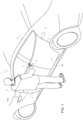
- reference number 1 is used to indicate, as a whole, a motor vehicle.
- the motor vehicle 1 comprises a body 2 and a plurality of side doors, in particular a front side door 3 and a rear side door 4.
- Each one of the doors 3, 4 is hinged to the body 2 so that it can rotate around an axis towards a side of the vehicle, in particular the same side where the doors 3, 4 are located, i.e. the side where a user U is shown in figure 1 .
- the axis is substantially vertical, meaning that the inclination of the axis relative to a vertical direction could range, for example, from 0° to 30°.
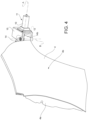
- the doors 3, 4 are shown in a closed configuration. Each one of the doors 3, 4 can rotate between the closed configuration and an open configuration, for example a completely open configuration, like in figure 4 .
- the motor vehicle 1 comprises an opening device 5, schematically shown in figure 1 , to open the door 4.
- the opening device 5 is motorized and is controllable to move the door 4 from the closed configuration towards the open configuration.
- the opening device 5 also is conveniently controllable to close the door 4, namely to move the latter from the open configuration towards the closed configuration.
- the opening device 5 moves the door 4 in an autonomous manner, namely without any intervention of the user U.
- the motor vehicle 1 can also comprise a lock device 6 controllable to lock the door 4 in the closed configuration and to further unlock the door 4 locked in the closed configuration.
- the lock device 6 could be controlled by the user U by means of a remote control not shown herein.
- the motor vehicle 1 comprises a command receiving device 7, which is configured to receive an opening request command for the door 4 from the outside of the motor vehicle 1.
- the device 7 comprise a member that be touched from the outside of the motor vehicle 1, for example a lever, which is well visible in figure 2 .
- the touchable member could be a button or even a touch-sensitive surface, for example of the capacitive or inductive type or the like, or a heat-sensitive surface.
- the touchable member is preferably coupled to the body 2. Furthermore, the touchable member conveniently is separate from the door 4.
- the opening request command comes from the user U, who touches the device 7, as shown in figure 2 .
- the device could comprise an electromagnetic signal receiver. Therefore, the opening request command could be an electromagnetic signal, for example emitted by an electronic device, for example a remote control, a mobile phone and the like, according to a corresponding command of the user U.
- the motor vehicle 1 further comprises a control unit ECU coupled to the devices 5, 7.
- the control unit ECU is configured to control the opening device 5 in response to the opening request command received by the device 7, so that the door 4 rotates from the closed configuration towards the open configuration.
- the control unit ECU can also be configured to control the opening device 5 so that the door 4 rotates in the opposite direction, namely from the open configuration towards the closed configuration, for example based on a closing request command coming from a suitable device non shown herein and coupled to the control unit ECU.
- control unit ECU control the opening device 5 so that the door 4 reaches an intermediate configuration between the open - in particular, completely open - configuration and the closed configuration.
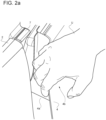
- the intermediate configuration is shown, in particular, in figure 2a .
- the intermediate configuration is a presenter configuration or, better said, an open presenter configuration, meaning that the door 4 is slightly open by an angle that is sufficient to expose to the user U the end 4a opposite the hinged one.
- the door 4 rotates by an angle ranging from 2° to 20°, preferably of 5°.
- the door 4 open in the intermediate configuration allows the user U to introduce a hand between the body 2 and the door 4, so that the user U can manually push or grab the door 4, more precisely the end 4a. By so doing, the user U can move the door 4 towards the open configuration.
- the door 4 does not need any handle or graspable element, which allows the user U to move the door 4.
- the door 4 externally lacks handles, graspable elements or graspable portions designed to allow or make it easier for the user to grasp the door 4 and/or rotate the door 4 from the closed configuration towards the open configuration.
- the door 4 has an outer surface 4b, which has no protuberances or recesses of any kind, which allow the user U the grasp the door, specifically from the outside of the motor vehicle 1.
- the user U can only lay or press a palm of the hand against the surface 4b.
- the user U cannot grab the door 4 and cannot introduce the fingers in a recess thereof.
- the surface 4b looks like a continuous surface without corners. Furthermore, the surface 4b is continuous and flush with the body 2 or outer body of the motor vehicle 1.
- the device 5 comprises a motor 10, for example an electric or hydraulic motor, controllable by the control unit ECU.
- the motor 10 is coupled to the control unit ECU.
- the motor 10 is a servo-motor.
- the motor 10 could be a rotary motor or a linear motor.
- the motor 10 comprises at least one casing or a portion carried by the body 2 in a fixed position relative to the body 2.
- the device 5 comprises a pushing assembly 11 operable by the motor 10 to exert a thrust upon the door 4.
- the pushing assembly 11 is conveniently carried by the body 2.
- the pushing assembly 11 can be manufactured in many ways and can contain one or more transmissions, kinematic mechanisms, gears, articulated mechanisms designed to exert the thrust upon the door 4.
- the pushing assembly 11 could include a crank train mechanism configured to convert a rotary motion of the motor 10 into a translation motion exerting the thrust.
- the pushing assembly 11 could include one or more speed reduction devices, such as gears or a transmission with a flexible drive member, in particular including one or more pulleys and, for example, a belt wound around the pulleys.
- speed reduction devices such as gears or a transmission with a flexible drive member, in particular including one or more pulleys and, for example, a belt wound around the pulleys.
- the thrust exerted by the assembly 11 is transversal, more precisely orthogonal to the door 4. Furthermore, the assembly 11 exerts the thrust from the inside of the motor vehicle 1.
- the thrust can be exerted both towards the outside and towards the inside of the motor vehicle 1, based on whether the device 5 is used to open or close the door 4, respectively.
- the terms "open” and “close” mean moving the door 4 towards the open and closed configuration, respectively.
- the assembly 11 comprises at least one pushing portion 12, which is movable, through translation, along a straight axis or direction A, specifically parallel to the forward moving direction of the motor vehicle 1 or parallel to the direction of extension of the door 4 in the closed configuration.
- the pushing portion 12 is carried by the body 2 in a movable manner, through translation, along the axis A.
- the portion is constrained relative to the body 2 with at least one degree of freedom of translation relative to the body 2.
- the pushing portion 12 translates, namely relative to the body 2 along the axis A.
- the axis A is fixed relative to the body 2.
- the assembly 11 preferably comprises a transmission, for example a crank train mechanism in case the motor 10 is a rotary motor or a straight rod in case the motor is a linear motor, configured to transmit an output of the motor 10, for example a torque or an output speed thereof, to the pushing portion 12, so that the latter translates in response to the output of the motor 10.
- a transmission for example a crank train mechanism in case the motor 10 is a rotary motor or a straight rod in case the motor is a linear motor, configured to transmit an output of the motor 10, for example a torque or an output speed thereof, to the pushing portion 12, so that the latter translates in response to the output of the motor 10.
- the pushing portion 12 exerts the transversal thrust upon the door 4.
- the pushing portion 12 exerts the thrust by means of an arm 14, which is coupled to the door 4 and to the pushing portion 12.
- the arm 14 is fixed to the door 4.
- the assembly 11 comprises a structure 15 to which the arm 14 is hinged. More in particular, the structure 15 is fixed relative to the body 2.
- the pushing portion 12 is preferably carried by the structure 15.
- the arm 14 comprises an end 14a fixed to the door 4 and an end 14b hinged to the structure 15 around a hinge axis B transversal, more precisely orthogonal to the direction A.
- the coupling of the pushing portion 12 to the arm 14 is such that the translation of the pushing portion 12 along the direction A causes the rotation of the arm 14 around the axis B.
- the arm 14 rotates in response to the translation of the pushing portion 12.
- the pushing portion 12 can be fixed to the arm 14.
- the pushing portion 12 is coupled to the arm 14 in an intermediate position between the ends 14a, 14b.
- the pushing portion 12 pushes the arm 14 at the intermediate position.
- the arm 14 rotates around the axis B, thus pushing the door 4.
- the arm 14 preferably has a curved or hook-like shape.
- the shape of the arm 14 is such that the thrust of the pushing portion 12 along the axis A in the area of the intermediate portion corresponds to a transversal thrust exerted upon the door 4 in the area of the end 14a.
- the door 4 is in the closed configuration.
- the device 7 receives the opening request command.
- control unit ECU identifies the receipt of the opening request command and controls the opening device 5.
- the opening device 5 is controlled so as to move the door 4 to the intermediate presenter configuration. Then, the user U can move the door 4 until it reaches the open configuration, which is shown in figure 4 .
- the opening device 5 does not prevent the opening configuration from being reached, as shown in figure 4 . Indeed, the pushing portion 12 can keep translating from a position corresponding to the intermediate presenter configuration towards a position corresponding to the open configuration and vice versa.
- the control unit ECU can even control the opening device 5 so as to move the door 4 to the open - more precisely, completely open - configuration by means of the motor 10, without interventions of the user U.
- the opening device 5 controlled by the control unit ECU can accompany the movement of the door 4 pushed by the user U, specifically through the motor 10.
- the closing of the door 4 can take place by means of the opening device 5 in a reverse manner compared to the opening of the door 4.
- control unit ECU can control the opening device 5 so as to close the door 4.
- the closing of the door 4, in a reverse manner relative to the opening of the door 4, could also be considered in an independent manner relative to the opening of the door 4.
- the control unit ECU could control the opening device 5 so as to close the door 4 in an independent manner relative to the control of the opening device 5 to open the door 4.
- the motor 10 can be controlled so as to adjust the closing speed of the door 4.
- the control unit ECU can control the motor 10 so that the closing speed of the door 4 is limited by a maximum value, which can be predetermined or selected by the user U.
- the order of magnitude of the maximum value is 0.8 rad/s.
- control unit ECU can control a gradual closing of the door 4 by means of the opening device 5, without intervention of the user U, especially from the intermediate presenter configuration towards the closed configuration.
- the closing could take place in two distinct and independent times: a first movement from the opening configuration to the intermediate presenter configuration and a second movement from the intermediate presenter configuration to the closed configuration.
- the opening and, if necessary, the closing of the door 4 take place in an extremely simple and safe fashion, as well as in a semi-automatic manner.
- the lack of handles or apprehensible portions on the surface 4b is advantageous both in aesthetic terms and in technical terms.
- the aerodynamic of the motor vehicle 1 benefits from this lack.
- theft-related safety is increased as well.
- the shape of the door 4 is necessarily simplified.
Landscapes
- Engineering & Computer Science (AREA)
- Mechanical Engineering (AREA)
- Computer Networks & Wireless Communication (AREA)
- Power-Operated Mechanisms For Wings (AREA)
- Control Of Throttle Valves Provided In The Intake System Or In The Exhaust System (AREA)
- Control Of Motors That Do Not Use Commutators (AREA)
- Reciprocating, Oscillating Or Vibrating Motors (AREA)
- Lock And Its Accessories (AREA)
Abstract
Description
- This patent application claims priority from
Italian patent application no. 102021000028820 filed on November 12, 2021 - The invention relates to a motor vehicle, for example a sports car, and more specifically to a door thereof and to a relative door opening device.
- As everybody knows, car doors are manually opened from the outside through a door handle, which usually also includes a manual control, for example a button or a lever, to unlock a lock of the door.
- Generally speaking, known motor vehicles need to be improved, in particular by increasing door opening comfort, when the door has to be opened from the outside of the motor vehicle, though without jeopardizing the safety of the motor vehicle in case of theft and of the people or objects surrounding the motor vehicle.
- The object of the invention is to fulfil the need discussed above, preferably in a simple and effective fashion.
- Said object is reached by a motor vehicle as defined in claim 1.
- The dependent claims define particular embodiments of the invention.
- Hereinafter, an embodiment of the invention will be described, in order to allow the latter to be better understood, by way of non-limiting example and with reference to the accompanying drawings, wherein:
-
figure 1 is a perspective view of a motor vehicle according to the invention; -
figure 2 shows, on a larger scale, a detail of the motor vehicle offigure 1 ; -
figure 2a is a further perspective view of an area of the motor vehicle comprising a door portion, in particular shown in an open presenter configuration; -
figures 3 and4 are further perspective views of the door, in a closed and open configuration respectively, specifically completely open. - In
figure 1 , reference number 1 is used to indicate, as a whole, a motor vehicle. - The motor vehicle 1 comprises a
body 2 and a plurality of side doors, in particular a front side door 3 and arear side door 4. - Each one of the
doors 3, 4 is hinged to thebody 2 so that it can rotate around an axis towards a side of the vehicle, in particular the same side where thedoors 3, 4 are located, i.e. the side where a user U is shown infigure 1 . In other words, the axis is substantially vertical, meaning that the inclination of the axis relative to a vertical direction could range, for example, from 0° to 30°. - In
figure 1 , thedoors 3, 4 are shown in a closed configuration. Each one of thedoors 3, 4 can rotate between the closed configuration and an open configuration, for example a completely open configuration, like infigure 4 . - Hereinafter, for brevity reasons, reference will be made to only one of the
doors 3, 4, specifically thedoor 4, assuming that the information disclosed below could be applied, alternatively or in addition, to the door 3. - The motor vehicle 1 comprises an
opening device 5, schematically shown infigure 1 , to open thedoor 4. - The
opening device 5 is motorized and is controllable to move thedoor 4 from the closed configuration towards the open configuration. - Furthermore, the
opening device 5 also is conveniently controllable to close thedoor 4, namely to move the latter from the open configuration towards the closed configuration. - In other words, the
opening device 5 moves thedoor 4 in an autonomous manner, namely without any intervention of the user U. - Besides the
opening device 5, the motor vehicle 1 can also comprise a lock device 6 controllable to lock thedoor 4 in the closed configuration and to further unlock thedoor 4 locked in the closed configuration. For example, the lock device 6 could be controlled by the user U by means of a remote control not shown herein. - In order to operate the
opening device 5, the motor vehicle 1 comprises acommand receiving device 7, which is configured to receive an opening request command for thedoor 4 from the outside of the motor vehicle 1. - Specifically, the
device 7 comprise a member that be touched from the outside of the motor vehicle 1, for example a lever, which is well visible infigure 2 . Alternatively, the touchable member could be a button or even a touch-sensitive surface, for example of the capacitive or inductive type or the like, or a heat-sensitive surface. The touchable member is preferably coupled to thebody 2. Furthermore, the touchable member conveniently is separate from thedoor 4. - Hence, in this case, the opening request command comes from the user U, who touches the
device 7, as shown infigure 2 . - This is not limiting; as a matter of
fact 7, the device could comprise an electromagnetic signal receiver. Therefore, the opening request command could be an electromagnetic signal, for example emitted by an electronic device, for example a remote control, a mobile phone and the like, according to a corresponding command of the user U. - The motor vehicle 1 further comprises a control unit ECU coupled to the
devices - The control unit ECU is configured to control the
opening device 5 in response to the opening request command received by thedevice 7, so that thedoor 4 rotates from the closed configuration towards the open configuration. - The control unit ECU can also be configured to control the
opening device 5 so that thedoor 4 rotates in the opposite direction, namely from the open configuration towards the closed configuration, for example based on a closing request command coming from a suitable device non shown herein and coupled to the control unit ECU. - More precisely, the control unit ECU control the
opening device 5 so that thedoor 4 reaches an intermediate configuration between the open - in particular, completely open - configuration and the closed configuration. - This intermediate configuration is shown, in particular, in
figure 2a . The intermediate configuration is a presenter configuration or, better said, an open presenter configuration, meaning that thedoor 4 is slightly open by an angle that is sufficient to expose to the user U theend 4a opposite the hinged one. - More precisely, from the closed configuration to the intermediate configuration, the
door 4 rotates by an angle ranging from 2° to 20°, preferably of 5°. - In other words, as shown in
figure 2a , thedoor 4 open in the intermediate configuration allows the user U to introduce a hand between thebody 2 and thedoor 4, so that the user U can manually push or grab thedoor 4, more precisely theend 4a. By so doing, the user U can move thedoor 4 towards the open configuration. - In this way, the
door 4 does not need any handle or graspable element, which allows the user U to move thedoor 4. - On the contrary, the
door 4 externally lacks handles, graspable elements or graspable portions designed to allow or make it easier for the user to grasp thedoor 4 and/or rotate thedoor 4 from the closed configuration towards the open configuration. - For example, the
door 4 has anouter surface 4b, which has no protuberances or recesses of any kind, which allow the user U the grasp the door, specifically from the outside of the motor vehicle 1. The user U can only lay or press a palm of the hand against thesurface 4b. On the other hand, the user U cannot grab thedoor 4 and cannot introduce the fingers in a recess thereof. - The
surface 4b looks like a continuous surface without corners. Furthermore, thesurface 4b is continuous and flush with thebody 2 or outer body of the motor vehicle 1. - The
device 5 comprises amotor 10, for example an electric or hydraulic motor, controllable by the control unit ECU. In fact, themotor 10 is coupled to the control unit ECU. In other words, themotor 10 is a servo-motor. - The
motor 10 could be a rotary motor or a linear motor. - In particular, the
motor 10 comprises at least one casing or a portion carried by thebody 2 in a fixed position relative to thebody 2. - Furthermore, the
device 5 comprises a pushingassembly 11 operable by themotor 10 to exert a thrust upon thedoor 4. - The pushing
assembly 11 is conveniently carried by thebody 2. - The pushing
assembly 11 can be manufactured in many ways and can contain one or more transmissions, kinematic mechanisms, gears, articulated mechanisms designed to exert the thrust upon thedoor 4. - For example, the pushing
assembly 11 could include a crank train mechanism configured to convert a rotary motion of themotor 10 into a translation motion exerting the thrust. - Furthermore, for example, the pushing
assembly 11 could include one or more speed reduction devices, such as gears or a transmission with a flexible drive member, in particular including one or more pulleys and, for example, a belt wound around the pulleys. - The thrust exerted by the
assembly 11 is transversal, more precisely orthogonal to thedoor 4. Furthermore, theassembly 11 exerts the thrust from the inside of the motor vehicle 1. - The thrust can be exerted both towards the outside and towards the inside of the motor vehicle 1, based on whether the
device 5 is used to open or close thedoor 4, respectively. In order to avoid misunderstandings, the terms "open" and "close" mean moving thedoor 4 towards the open and closed configuration, respectively. - The
assembly 11 comprises at least one pushingportion 12, which is movable, through translation, along a straight axis or direction A, specifically parallel to the forward moving direction of the motor vehicle 1 or parallel to the direction of extension of thedoor 4 in the closed configuration. - The pushing
portion 12 is carried by thebody 2 in a movable manner, through translation, along the axis A. In other words, the portion is constrained relative to thebody 2 with at least one degree of freedom of translation relative to thebody 2. Still in other words, the pushingportion 12 translates, namely relative to thebody 2 along the axis A. - In particular, the axis A is fixed relative to the
body 2. - Furthermore, the
assembly 11 preferably comprises a transmission, for example a crank train mechanism in case themotor 10 is a rotary motor or a straight rod in case the motor is a linear motor, configured to transmit an output of themotor 10, for example a torque or an output speed thereof, to the pushingportion 12, so that the latter translates in response to the output of themotor 10. - By translating, the pushing
portion 12 exerts the transversal thrust upon thedoor 4. - More in detail, the pushing
portion 12 exerts the thrust by means of anarm 14, which is coupled to thedoor 4 and to the pushingportion 12. - More precisely, the
arm 14 is fixed to thedoor 4. - In particular, the
assembly 11 comprises astructure 15 to which thearm 14 is hinged. More in particular, thestructure 15 is fixed relative to thebody 2. - The pushing
portion 12 is preferably carried by thestructure 15. - The
arm 14 comprises anend 14a fixed to thedoor 4 and anend 14b hinged to thestructure 15 around a hinge axis B transversal, more precisely orthogonal to the direction A. - The coupling of the pushing
portion 12 to thearm 14 is such that the translation of the pushingportion 12 along the direction A causes the rotation of thearm 14 around the axis B. - Namely, the
arm 14 rotates in response to the translation of the pushingportion 12. - For example, the pushing
portion 12 can be fixed to thearm 14. - The pushing
portion 12 is coupled to thearm 14 in an intermediate position between theends - Therefore, by translating along the direction A, the pushing
portion 12 pushes thearm 14 at the intermediate position. By so doing, thearm 14 rotates around the axis B, thus pushing thedoor 4. - The
arm 14 preferably has a curved or hook-like shape. In other words, the shape of thearm 14 is such that the thrust of the pushingportion 12 along the axis A in the area of the intermediate portion corresponds to a transversal thrust exerted upon thedoor 4 in the area of theend 14a. - The operation of the motor vehicle 1 is described by
figures 3 and4 . - In
figure 3 , thedoor 4 is in the closed configuration. When the user U or a suitable electronic device issues the opening request command, thedevice 7 receives the opening request command. - At this point, the control unit ECU identifies the receipt of the opening request command and controls the
opening device 5. - The
opening device 5 is controlled so as to move thedoor 4 to the intermediate presenter configuration. Then, the user U can move thedoor 4 until it reaches the open configuration, which is shown infigure 4 . - The
opening device 5 does not prevent the opening configuration from being reached, as shown infigure 4 . Indeed, the pushingportion 12 can keep translating from a position corresponding to the intermediate presenter configuration towards a position corresponding to the open configuration and vice versa. - The control unit ECU can even control the
opening device 5 so as to move thedoor 4 to the open - more precisely, completely open - configuration by means of themotor 10, without interventions of the user U. - Hence, the
opening device 5 controlled by the control unit ECU can accompany the movement of thedoor 4 pushed by the user U, specifically through themotor 10. - The closing of the
door 4 can take place by means of theopening device 5 in a reverse manner compared to the opening of thedoor 4. - Namely, the control unit ECU can control the
opening device 5 so as to close thedoor 4. - The closing of the
door 4, in a reverse manner relative to the opening of thedoor 4, could also be considered in an independent manner relative to the opening of thedoor 4. In other words, the control unit ECU could control theopening device 5 so as to close thedoor 4 in an independent manner relative to the control of theopening device 5 to open thedoor 4. - During the closing, the
motor 10 can be controlled so as to adjust the closing speed of thedoor 4. For example, the control unit ECU can control themotor 10 so that the closing speed of thedoor 4 is limited by a maximum value, which can be predetermined or selected by the user U. For example, the order of magnitude of the maximum value is 0.8 rad/s. - In particular, the control unit ECU can control a gradual closing of the
door 4 by means of theopening device 5, without intervention of the user U, especially from the intermediate presenter configuration towards the closed configuration. - Hence, the closing could take place in two distinct and independent times: a first movement from the opening configuration to the intermediate presenter configuration and a second movement from the intermediate presenter configuration to the closed configuration.
- Owing to the above, the advantages of the motor vehicle 1 according to the invention are evident.
- The opening and, if necessary, the closing of the
door 4 take place in an extremely simple and safe fashion, as well as in a semi-automatic manner. - The lack of handles or apprehensible portions on the
surface 4b is advantageous both in aesthetic terms and in technical terms. In particular, the aerodynamic of the motor vehicle 1 benefits from this lack. Furthermore, theft-related safety is increased as well. In addition, the shape of thedoor 4 is necessarily simplified. - Finally, the motor vehicle 1 according to the invention can be subjected to changes and variants, which, though, do not go beyond the scope of protection set forth in the appended claims.
Claims (8)
- - A motor vehicle (1) comprising:- a body (2),- a side door (4) hinged to the body (2) in a manner to be rotatable about an axis towards a side of the motor vehicle (1) between a closed configuration and an open configuration;- a motorized opening device (5), which is controllable to move the door (4) from the closed configuration towards the open configuration;- command receiving means (7) to receive an opening request command for the door (4) from the outside of the motor vehicle (1); and- a control unit (ECU) configured to control the opening device (5) so that the door (4) rotates from the closed configuration towards the open configuration in response to the opening request command.
- - The motor vehicle according to claim 1, wherein the door (4) externally lacks apprehensible portions suitable for allowing a user (U) to grasp the door (4) and consequently rotate the door (4) from the closed configuration towards the open configuration.
- - The motor vehicle according to claim 1 or 2, wherein the control unit (ECU) is configured to control the opening device (5) in response to the opening request command so that the door (4) rotates from the closed configuration to an intermediate presenter configuration between the open configuration and the closed configuration.
- - The motor vehicle according to any one of the preceding claims, wherein the command receiving means (7) comprise a member being touchable from the outside of the motor vehicle (1).
- - The motor vehicle according to any one of the preceding claims, wherein the command receiving means (7) comprise an electromagnetic signal receiver.
- - The motor vehicle according to any one of the preceding claims, wherein the opening device (5) comprises- a motor (10) controllable by the control unit (ECU); and- a pushing assembly (11) operable by the motor (10) to exert a transversal thrust upon the door (4);wherein the pushing assembly (11) comprises- at least one thrust portion (12), which is movable, through translation, along a straight direction (A);- a transmission configured to transmit an output of the motor (10) to the thrust portion (12) so that the thrust portion (12) translates in response to the output of the motor (10), thereby exerting said thrust.
- - The motor vehicle according to claim 6, wherein the straight direction (A) substantially extends along a forward moving direction of the motor vehicle (1).
- - The motor vehicle according to claim 6 or 7, wherein the pushing assembly (11) comprises a fixed structure (15) and a curved arm (14), the arm (14) comprising- a first end (14a), which is fixed to the door (4); and- a second end (14b), which is hinged to the structure (15) about a hinge axis (B) transversal to the straight direction (A),wherein the thrust portion (12) is coupled to the arm (14) so that the arm (14) rotates in response to a translation of the thrust portion (12).
Applications Claiming Priority (1)
| Application Number | Priority Date | Filing Date | Title |
|---|---|---|---|
| IT102021000028820A IT202100028820A1 (en) | 2021-11-12 | 2021-11-12 | MOTOR VEHICLE |
Publications (2)
| Publication Number | Publication Date |
|---|---|
| EP4180609A1 true EP4180609A1 (en) | 2023-05-17 |
| EP4180609B1 EP4180609B1 (en) | 2026-04-15 |
Family
ID=79831676
Family Applications (1)
| Application Number | Title | Priority Date | Filing Date |
|---|---|---|---|
| EP22206600.3A Active EP4180609B1 (en) | 2021-11-12 | 2022-11-10 | Motor vehicle |
Country Status (5)
| Country | Link |
|---|---|
| US (1) | US12486712B2 (en) |
| EP (1) | EP4180609B1 (en) |
| JP (1) | JP2023072678A (en) |
| CN (1) | CN116122678A (en) |
| IT (1) | IT202100028820A1 (en) |
Cited By (1)
| Publication number | Priority date | Publication date | Assignee | Title |
|---|---|---|---|---|
| WO2026057506A1 (en) * | 2024-09-11 | 2026-03-19 | Jaguar Land Rover Limited | A hinge arm for a vehicle door |
Families Citing this family (4)
| Publication number | Priority date | Publication date | Assignee | Title |
|---|---|---|---|---|
| CN116513105A (en) * | 2023-05-18 | 2023-08-01 | 江西五十铃汽车有限公司 | Vehicle keyless entry method and system |
| DE102023124237A1 (en) | 2023-09-08 | 2025-03-13 | Contitech Deutschland Gmbh | Door drive and motor vehicle equipped with it |
| DE102023125633A1 (en) | 2023-09-21 | 2025-03-27 | Contitech Deutschland Gmbh | Door drive and motor vehicle equipped with it |
| DE102023126226A1 (en) | 2023-09-27 | 2025-03-27 | Contitech Deutschland Gmbh | Door drive and motor vehicle equipped with it |
Citations (3)
| Publication number | Priority date | Publication date | Assignee | Title |
|---|---|---|---|---|
| DE102015107609A1 (en) * | 2014-05-19 | 2015-11-19 | GM Global Technology Operations LLC (n. d. Gesetzen des Staates Delaware) | Vehicle with an assembly for opening a vehicle door |
| WO2017034809A1 (en) * | 2015-08-26 | 2017-03-02 | Tesla Motors, Inc. | Vehicle front door power opening system |
| US20200217107A1 (en) * | 2018-01-02 | 2020-07-09 | Ford Global Technologies, Llc | Door actuator with retraction device |
Family Cites Families (9)
| Publication number | Priority date | Publication date | Assignee | Title |
|---|---|---|---|---|
| JP3709099B2 (en) * | 1999-05-26 | 2005-10-19 | 株式会社大井製作所 | Opening and closing device for vehicle door |
| JP6583685B2 (en) * | 2016-01-21 | 2019-10-02 | 三井金属アクト株式会社 | Door opener |
| US10151132B2 (en) * | 2016-02-29 | 2018-12-11 | Ford Global Technologies, Llc | Power Management for vehicle door system |
| US10227810B2 (en) * | 2016-08-03 | 2019-03-12 | Ford Global Technologies, Llc | Priority driven power side door open/close operations |
| US10087671B2 (en) * | 2016-08-04 | 2018-10-02 | Ford Global Technologies, Llc | Powered driven door presenter for vehicle doors |
| US10711504B2 (en) * | 2016-08-16 | 2020-07-14 | Magna Closures Inc. | Power door presenter with latching feature |
| US11008780B2 (en) * | 2016-12-23 | 2021-05-18 | Magna Closures, Inc. | Power door presenter with latching feature |
| JP6984434B2 (en) * | 2018-01-23 | 2021-12-22 | 株式会社アイシン | Vehicle opening / closing body control device and vehicle opening / closing body control method |
| US11078691B2 (en) * | 2018-06-26 | 2021-08-03 | Ford Global Technologies, Llc | Deployable vehicle door handle |
-
2021
- 2021-11-12 IT IT102021000028820A patent/IT202100028820A1/en unknown
-
2022
- 2022-11-01 US US18/051,602 patent/US12486712B2/en active Active
- 2022-11-09 JP JP2022179185A patent/JP2023072678A/en active Pending
- 2022-11-10 EP EP22206600.3A patent/EP4180609B1/en active Active
- 2022-11-11 CN CN202211413775.2A patent/CN116122678A/en active Pending
Patent Citations (3)
| Publication number | Priority date | Publication date | Assignee | Title |
|---|---|---|---|---|
| DE102015107609A1 (en) * | 2014-05-19 | 2015-11-19 | GM Global Technology Operations LLC (n. d. Gesetzen des Staates Delaware) | Vehicle with an assembly for opening a vehicle door |
| WO2017034809A1 (en) * | 2015-08-26 | 2017-03-02 | Tesla Motors, Inc. | Vehicle front door power opening system |
| US20200217107A1 (en) * | 2018-01-02 | 2020-07-09 | Ford Global Technologies, Llc | Door actuator with retraction device |
Cited By (1)
| Publication number | Priority date | Publication date | Assignee | Title |
|---|---|---|---|---|
| WO2026057506A1 (en) * | 2024-09-11 | 2026-03-19 | Jaguar Land Rover Limited | A hinge arm for a vehicle door |
Also Published As
| Publication number | Publication date |
|---|---|
| EP4180609B1 (en) | 2026-04-15 |
| JP2023072678A (en) | 2023-05-24 |
| CN116122678A (en) | 2023-05-16 |
| US20230151673A1 (en) | 2023-05-18 |
| US12486712B2 (en) | 2025-12-02 |
| IT202100028820A1 (en) | 2023-05-12 |
Similar Documents
| Publication | Publication Date | Title |
|---|---|---|
| EP4180609A1 (en) | Motor vehicle | |
| JP6986951B2 (en) | Stepless opening operation unit | |
| US9080352B2 (en) | Controller apparatus and sensors for a vehicle door handle | |
| KR102139545B1 (en) | Door Entry Guide System and Operation Method of Door Entry Guide System | |
| US5588258A (en) | Power operator for pivotable vehicle closure element | |
| US5844470A (en) | Device for controlling opening of a motor vehicle door | |
| EP3263812B1 (en) | Retractable handle arrangement for a door or the like | |
| CN111356817A (en) | Opening device for a motor vehicle door | |
| EP1134104A1 (en) | A tailgate assembly for a motor vehicle | |
| JP2013533405A (en) | Openable / closable handle having a grip portion in a vehicle | |
| US20080217942A1 (en) | Handle for Vehicle Door | |
| EP3943695B1 (en) | Handle for a vehicle door | |
| US11207942B2 (en) | User-actuated air nozzle control mechanism and method for controlling the airflow | |
| JP7516705B2 (en) | Automotive door panel handle | |
| US20230220717A1 (en) | Closure latch assembly with integrated door presenter | |
| JP6299017B2 (en) | Vehicle door operating device | |
| WO2015182008A1 (en) | Vehicle door opening/closing device | |
| CN108884694A (en) | Door handle devices for motor vehicles | |
| CN118613627A (en) | Door for a motor vehicle and method for operating such a door | |
| JP2025082303A (en) | Vehicle door having extensible handle | |
| US6250013B1 (en) | Device for opening and closing an opening in a wall | |
| US20250020002A1 (en) | Operating Mechanism for Operating Vehicle Doors | |
| CN111648695A (en) | Automobile | |
| US7267390B2 (en) | Vehicle decklid system with planetary gear | |
| US12024937B2 (en) | Partial-opening device for a motor-vehicle door element |
Legal Events
| Date | Code | Title | Description |
|---|---|---|---|
| PUAI | Public reference made under article 153(3) epc to a published international application that has entered the european phase |
Free format text: ORIGINAL CODE: 0009012 |
|
| STAA | Information on the status of an ep patent application or granted ep patent |
Free format text: STATUS: THE APPLICATION HAS BEEN PUBLISHED |
|
| AK | Designated contracting states |
Kind code of ref document: A1 Designated state(s): AL AT BE BG CH CY CZ DE DK EE ES FI FR GB GR HR HU IE IS IT LI LT LU LV MC ME MK MT NL NO PL PT RO RS SE SI SK SM TR |
|
| STAA | Information on the status of an ep patent application or granted ep patent |
Free format text: STATUS: REQUEST FOR EXAMINATION WAS MADE |
|
| 17P | Request for examination filed |
Effective date: 20231107 |
|
| RBV | Designated contracting states (corrected) |
Designated state(s): AL AT BE BG CH CY CZ DE DK EE ES FI FR GB GR HR HU IE IS IT LI LT LU LV MC ME MK MT NL NO PL PT RO RS SE SI SK SM TR |
|
| RIN1 | Information on inventor provided before grant (corrected) |
Inventor name: DUSINI, LUCA |
|
| STAA | Information on the status of an ep patent application or granted ep patent |
Free format text: STATUS: EXAMINATION IS IN PROGRESS |
|
| 17Q | First examination report despatched |
Effective date: 20240909 |
|
| GRAP | Despatch of communication of intention to grant a patent |
Free format text: ORIGINAL CODE: EPIDOSNIGR1 |
|
| STAA | Information on the status of an ep patent application or granted ep patent |
Free format text: STATUS: GRANT OF PATENT IS INTENDED |
|
| INTG | Intention to grant announced |
Effective date: 20251013 |
|
| GRAJ | Information related to disapproval of communication of intention to grant by the applicant or resumption of examination proceedings by the epo deleted |
Free format text: ORIGINAL CODE: EPIDOSDIGR1 |
|
| STAA | Information on the status of an ep patent application or granted ep patent |
Free format text: STATUS: EXAMINATION IS IN PROGRESS |
|
| GRAP | Despatch of communication of intention to grant a patent |
Free format text: ORIGINAL CODE: EPIDOSNIGR1 |
|
| STAA | Information on the status of an ep patent application or granted ep patent |
Free format text: STATUS: GRANT OF PATENT IS INTENDED |
|
| INTG | Intention to grant announced |
Effective date: 20251124 |
|
| GRAS | Grant fee paid |
Free format text: ORIGINAL CODE: EPIDOSNIGR3 |
|
| GRAA | (expected) grant |
Free format text: ORIGINAL CODE: 0009210 |
|
| STAA | Information on the status of an ep patent application or granted ep patent |
Free format text: STATUS: THE PATENT HAS BEEN GRANTED |
|
| AK | Designated contracting states |
Kind code of ref document: B1 Designated state(s): AL AT BE BG CH CY CZ DE DK EE ES FI FR GB GR HR HU IE IS IT LI LT LU LV MC ME MK MT NL NO PL PT RO RS SE SI SK SM TR |
|
| REG | Reference to a national code |
Ref country code: CH Ref legal event code: F10 Free format text: ST27 STATUS EVENT CODE: U-0-0-F10-F00 (AS PROVIDED BY THE NATIONAL OFFICE) Effective date: 20260415 |