EP4180553A1 - Anticorrosion structure and manufacturing method therefor - Google Patents
Anticorrosion structure and manufacturing method therefor Download PDFInfo
- Publication number
- EP4180553A1 EP4180553A1 EP21836845.4A EP21836845A EP4180553A1 EP 4180553 A1 EP4180553 A1 EP 4180553A1 EP 21836845 A EP21836845 A EP 21836845A EP 4180553 A1 EP4180553 A1 EP 4180553A1
- Authority
- EP
- European Patent Office
- Prior art keywords
- silicone rubber
- anticorrosion
- group
- mold
- connection surface
- Prior art date
- Legal status (The legal status is an assumption and is not a legal conclusion. Google has not performed a legal analysis and makes no representation as to the accuracy of the status listed.)
- Withdrawn
Links
Images







Classifications
-
- F—MECHANICAL ENGINEERING; LIGHTING; HEATING; WEAPONS; BLASTING
- F16—ENGINEERING ELEMENTS AND UNITS; GENERAL MEASURES FOR PRODUCING AND MAINTAINING EFFECTIVE FUNCTIONING OF MACHINES OR INSTALLATIONS; THERMAL INSULATION IN GENERAL
- F16B—DEVICES FOR FASTENING OR SECURING CONSTRUCTIONAL ELEMENTS OR MACHINE PARTS TOGETHER, e.g. NAILS, BOLTS, CIRCLIPS, CLAMPS, CLIPS OR WEDGES; JOINTS OR JOINTING
- F16B33/00—Features common to bolt and nut
- F16B33/06—Surface treatment of parts furnished with screw-thread, e.g. for preventing seizure or fretting
-
- C—CHEMISTRY; METALLURGY
- C08—ORGANIC MACROMOLECULAR COMPOUNDS; THEIR PREPARATION OR CHEMICAL WORKING-UP; COMPOSITIONS BASED THEREON
- C08G—MACROMOLECULAR COMPOUNDS OBTAINED OTHERWISE THAN BY REACTIONS ONLY INVOLVING UNSATURATED CARBON-TO-CARBON BONDS
- C08G77/00—Macromolecular compounds obtained by reactions forming a linkage containing silicon with or without sulfur, nitrogen, oxygen or carbon in the main chain of the macromolecule
- C08G77/04—Polysiloxanes
- C08G77/12—Polysiloxanes containing silicon bound to hydrogen
-
- C—CHEMISTRY; METALLURGY
- C08—ORGANIC MACROMOLECULAR COMPOUNDS; THEIR PREPARATION OR CHEMICAL WORKING-UP; COMPOSITIONS BASED THEREON
- C08G—MACROMOLECULAR COMPOUNDS OBTAINED OTHERWISE THAN BY REACTIONS ONLY INVOLVING UNSATURATED CARBON-TO-CARBON BONDS
- C08G77/00—Macromolecular compounds obtained by reactions forming a linkage containing silicon with or without sulfur, nitrogen, oxygen or carbon in the main chain of the macromolecule
- C08G77/04—Polysiloxanes
- C08G77/14—Polysiloxanes containing silicon bound to oxygen-containing groups
-
- C—CHEMISTRY; METALLURGY
- C08—ORGANIC MACROMOLECULAR COMPOUNDS; THEIR PREPARATION OR CHEMICAL WORKING-UP; COMPOSITIONS BASED THEREON
- C08G—MACROMOLECULAR COMPOUNDS OBTAINED OTHERWISE THAN BY REACTIONS ONLY INVOLVING UNSATURATED CARBON-TO-CARBON BONDS
- C08G77/00—Macromolecular compounds obtained by reactions forming a linkage containing silicon with or without sulfur, nitrogen, oxygen or carbon in the main chain of the macromolecule
- C08G77/04—Polysiloxanes
- C08G77/14—Polysiloxanes containing silicon bound to oxygen-containing groups
- C08G77/16—Polysiloxanes containing silicon bound to oxygen-containing groups to hydroxy groups
-
- C—CHEMISTRY; METALLURGY
- C08—ORGANIC MACROMOLECULAR COMPOUNDS; THEIR PREPARATION OR CHEMICAL WORKING-UP; COMPOSITIONS BASED THEREON
- C08G—MACROMOLECULAR COMPOUNDS OBTAINED OTHERWISE THAN BY REACTIONS ONLY INVOLVING UNSATURATED CARBON-TO-CARBON BONDS
- C08G77/00—Macromolecular compounds obtained by reactions forming a linkage containing silicon with or without sulfur, nitrogen, oxygen or carbon in the main chain of the macromolecule
- C08G77/04—Polysiloxanes
- C08G77/14—Polysiloxanes containing silicon bound to oxygen-containing groups
- C08G77/18—Polysiloxanes containing silicon bound to oxygen-containing groups to alkoxy or aryloxy groups
-
- C—CHEMISTRY; METALLURGY
- C08—ORGANIC MACROMOLECULAR COMPOUNDS; THEIR PREPARATION OR CHEMICAL WORKING-UP; COMPOSITIONS BASED THEREON
- C08G—MACROMOLECULAR COMPOUNDS OBTAINED OTHERWISE THAN BY REACTIONS ONLY INVOLVING UNSATURATED CARBON-TO-CARBON BONDS
- C08G77/00—Macromolecular compounds obtained by reactions forming a linkage containing silicon with or without sulfur, nitrogen, oxygen or carbon in the main chain of the macromolecule
- C08G77/04—Polysiloxanes
- C08G77/20—Polysiloxanes containing silicon bound to unsaturated aliphatic groups
-
- C—CHEMISTRY; METALLURGY
- C08—ORGANIC MACROMOLECULAR COMPOUNDS; THEIR PREPARATION OR CHEMICAL WORKING-UP; COMPOSITIONS BASED THEREON
- C08K—Use of inorganic or non-macromolecular organic substances as compounding ingredients
- C08K5/00—Use of organic ingredients
- C08K5/56—Organo-metallic compounds, i.e. organic compounds containing a metal-to-carbon bond
-
- C—CHEMISTRY; METALLURGY
- C08—ORGANIC MACROMOLECULAR COMPOUNDS; THEIR PREPARATION OR CHEMICAL WORKING-UP; COMPOSITIONS BASED THEREON
- C08K—Use of inorganic or non-macromolecular organic substances as compounding ingredients
- C08K5/00—Use of organic ingredients
- C08K5/56—Organo-metallic compounds, i.e. organic compounds containing a metal-to-carbon bond
- C08K5/57—Organo-tin compounds
-
- C—CHEMISTRY; METALLURGY
- C08—ORGANIC MACROMOLECULAR COMPOUNDS; THEIR PREPARATION OR CHEMICAL WORKING-UP; COMPOSITIONS BASED THEREON
- C08L—COMPOSITIONS OF MACROMOLECULAR COMPOUNDS
- C08L83/00—Compositions of macromolecular compounds obtained by reactions forming in the main chain of the macromolecule a linkage containing silicon with or without sulfur, nitrogen, oxygen or carbon only; Compositions of derivatives of such polymers
- C08L83/04—Polysiloxanes
-
- C—CHEMISTRY; METALLURGY
- C08—ORGANIC MACROMOLECULAR COMPOUNDS; THEIR PREPARATION OR CHEMICAL WORKING-UP; COMPOSITIONS BASED THEREON
- C08L—COMPOSITIONS OF MACROMOLECULAR COMPOUNDS
- C08L83/00—Compositions of macromolecular compounds obtained by reactions forming in the main chain of the macromolecule a linkage containing silicon with or without sulfur, nitrogen, oxygen or carbon only; Compositions of derivatives of such polymers
- C08L83/04—Polysiloxanes
- C08L83/06—Polysiloxanes containing silicon bound to oxygen-containing groups
-
- C—CHEMISTRY; METALLURGY
- C09—DYES; PAINTS; POLISHES; NATURAL RESINS; ADHESIVES; COMPOSITIONS NOT OTHERWISE PROVIDED FOR; APPLICATIONS OF MATERIALS NOT OTHERWISE PROVIDED FOR
- C09D—COATING COMPOSITIONS, e.g. PAINTS, VARNISHES OR LACQUERS; FILLING PASTES; CHEMICAL PAINT OR INK REMOVERS; INKS; CORRECTING FLUIDS; WOODSTAINS; PASTES OR SOLIDS FOR COLOURING OR PRINTING; USE OF MATERIALS THEREFOR
- C09D183/00—Coating compositions based on macromolecular compounds obtained by reactions forming in the main chain of the macromolecule a linkage containing silicon, with or without sulfur, nitrogen, oxygen, or carbon only; Coating compositions based on derivatives of such polymers
- C09D183/04—Polysiloxanes
-
- C—CHEMISTRY; METALLURGY
- C09—DYES; PAINTS; POLISHES; NATURAL RESINS; ADHESIVES; COMPOSITIONS NOT OTHERWISE PROVIDED FOR; APPLICATIONS OF MATERIALS NOT OTHERWISE PROVIDED FOR
- C09D—COATING COMPOSITIONS, e.g. PAINTS, VARNISHES OR LACQUERS; FILLING PASTES; CHEMICAL PAINT OR INK REMOVERS; INKS; CORRECTING FLUIDS; WOODSTAINS; PASTES OR SOLIDS FOR COLOURING OR PRINTING; USE OF MATERIALS THEREFOR
- C09D5/00—Coating compositions, e.g. paints, varnishes or lacquers, characterised by their physical nature or the effects produced; Filling pastes
- C09D5/08—Anti-corrosive paints
-
- C—CHEMISTRY; METALLURGY
- C09—DYES; PAINTS; POLISHES; NATURAL RESINS; ADHESIVES; COMPOSITIONS NOT OTHERWISE PROVIDED FOR; APPLICATIONS OF MATERIALS NOT OTHERWISE PROVIDED FOR
- C09J—ADHESIVES; NON-MECHANICAL ASPECTS OF ADHESIVE PROCESSES IN GENERAL; ADHESIVE PROCESSES NOT PROVIDED FOR ELSEWHERE; USE OF MATERIALS AS ADHESIVES
- C09J183/00—Adhesives based on macromolecular compounds obtained by reactions forming in the main chain of the macromolecule a linkage containing silicon, with or without sulfur, nitrogen, oxygen, or carbon only; Adhesives based on derivatives of such polymers
- C09J183/04—Polysiloxanes
-
- C—CHEMISTRY; METALLURGY
- C23—COATING METALLIC MATERIAL; COATING MATERIAL WITH METALLIC MATERIAL; CHEMICAL SURFACE TREATMENT; DIFFUSION TREATMENT OF METALLIC MATERIAL; COATING BY VACUUM EVAPORATION, BY SPUTTERING, BY ION IMPLANTATION OR BY CHEMICAL VAPOUR DEPOSITION, IN GENERAL; INHIBITING CORROSION OF METALLIC MATERIAL OR INCRUSTATION IN GENERAL
- C23F—NON-MECHANICAL REMOVAL OF METALLIC MATERIAL FROM SURFACE; INHIBITING CORROSION OF METALLIC MATERIAL OR INCRUSTATION IN GENERAL; MULTI-STEP PROCESSES FOR SURFACE TREATMENT OF METALLIC MATERIAL INVOLVING AT LEAST ONE PROCESS PROVIDED FOR IN CLASS C23 AND AT LEAST ONE PROCESS COVERED BY SUBCLASS C21D OR C22F OR CLASS C25
- C23F15/00—Other methods of preventing corrosion or incrustation
-
- F—MECHANICAL ENGINEERING; LIGHTING; HEATING; WEAPONS; BLASTING
- F16—ENGINEERING ELEMENTS AND UNITS; GENERAL MEASURES FOR PRODUCING AND MAINTAINING EFFECTIVE FUNCTIONING OF MACHINES OR INSTALLATIONS; THERMAL INSULATION IN GENERAL
- F16B—DEVICES FOR FASTENING OR SECURING CONSTRUCTIONAL ELEMENTS OR MACHINE PARTS TOGETHER, e.g. NAILS, BOLTS, CIRCLIPS, CLAMPS, CLIPS OR WEDGES; JOINTS OR JOINTING
- F16B33/00—Features common to bolt and nut
- F16B33/008—Corrosion preventing means
-
- F—MECHANICAL ENGINEERING; LIGHTING; HEATING; WEAPONS; BLASTING
- F16—ENGINEERING ELEMENTS AND UNITS; GENERAL MEASURES FOR PRODUCING AND MAINTAINING EFFECTIVE FUNCTIONING OF MACHINES OR INSTALLATIONS; THERMAL INSULATION IN GENERAL
- F16B—DEVICES FOR FASTENING OR SECURING CONSTRUCTIONAL ELEMENTS OR MACHINE PARTS TOGETHER, e.g. NAILS, BOLTS, CIRCLIPS, CLAMPS, CLIPS OR WEDGES; JOINTS OR JOINTING
- F16B37/00—Nuts or like thread-engaging members
- F16B37/14—Cap nuts; Nut caps or bolt caps
-
- H—ELECTRICITY
- H02—GENERATION; CONVERSION OR DISTRIBUTION OF ELECTRIC POWER
- H02G—INSTALLATION OF ELECTRIC CABLES OR LINES, OR OF COMBINED OPTICAL AND ELECTRIC CABLES OR LINES
- H02G7/00—Overhead installations of electric lines or cables
Definitions
- the present invention relates to an anticorrosion structure and a method for producing the same.
- anticorrosion members are generally produced using a resin such as vinyl chloride or an epoxy resin. Therefore, in an anticorrosion structure including the above-described anticorrosion member in a connecting part using at least one of a metal bolt and a metal nut, the anticorrosion member may be cracked or cleaved, or the anticorrosion member may be lifted due to aging, and if the anticorrosion member is left as it is, the anticorrosion effect might be degraded. Accordingly, there is a demand for an anticorrosion structure having a high anticorrosion effect.
- the present invention was devised in consideration of the above-described problems, and an object is to provide an anticorrosion structure having a high anticorrosion effect, and a method for producing the same.
- an anticorrosion structure having a high anticorrosion effect and a method for producing the same can be provided.
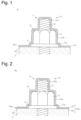
- Figure 1 shows a vertical cross-sectional view of an anticorrosion structure according to a first embodiment.
- vertical cross-sectional view means a view obtained by vertically cutting the structure in a direction from a volt leg toward a nut. The same applies to the other embodiments described below.
- An anticorrosion structure 6 includes at least one of a metal bolt 2 and a metal nut 3, and an anticorrosion member 1 coating a portion, protruding beyond a connection surface 50, of a connecting part using the at least one of the bolt 2 and the nut 3.
- the term "metal” means a metal not particularly limited such as iron or an iron-based alloy (including SUS).
- the anticorrosion member 1 includes a main body 10 formed of a silicone rubber obtained by curing a silicone rubber compound.
- the anticorrosion member 1 also includes a coating layer 20 preferably formed of a silicone rubber for coating the connection surface 50.
- the anticorrosion member 1 coats the portion, protruding beyond the connection surface 50, of the connecting part using the bolt 2 and the nut 3 connected to a structure 5. Now, constituent elements of the anticorrosion member 1 provided in the anticorrosion structure 6 will be described in detail.
- the main body 10 is a member for coating the portion, protruding beyond the connection surface 50, of the connecting part using the bolt 2 and the nut 3.
- the main body 10 includes a recess 12 where the portion of the connecting part protruding beyond the connection surface 50 is disposed.
- the main body 10 includes, for example, a head portion 10a coating a screw portion (leg portion) of the bolt 2 protruding beyond the nut 3, a trunk portion 10b coating a side surface portion of the nut 3, and a flange portion 10c coating a washer 4 disposed between the nut 3 and the connection surface 50.
- the main body 10 is preferably configured in a shape according to the shape of the member to be disposed in the recess 12 (such as the screw portion of the bolt 2, the nut 3, and the washer 4).
- the shapes of the main body 10 and the recess 12 are not limited to the shapes illustrated in Figure 1 , but are preferably appropriately designed according to the shape of the member to be disposed in the recess 12. For example, if the washer 4 is not used in the connecting part, the flange portion 10c may not be provided.
- the silicone rubber is a rubber-like elastic body having a siloxane bond (-Si-O-Si) as a main skeleton.
- a silicone rubber usable in this embodiment may be obtained by any of curing types such as addition curing type, condensation reaction type, UV curing type, and electron beam curing type, and is preferably an addition-curing type silicone rubber in particular.
- the silicone rubber is a rubber-like elastic body obtained by curing a curable organopolysiloxane composition containing an organopolysiloxane as a main agent (silicone rubber compound).
- the term "main agent” means an agent having a largest mass ratio among components contained in the curable organopolysiloxane composition.
- the organopolysiloxane is contained in the curable organopolysiloxane composition preferably in an amount of 50% by mass or more, and the amount may be less than 50% by mass as far as it is the main agent.
- silicone rubber compound used as a raw material before curing the silicone rubber examples of addition-curing type and condensation curing type curable organopolysiloxane compositions will be described.
- the addition-curing type curable organopolysiloxane composition may be designated as an addition-curing type curable silicone composition or an addition-curing type curable silicone rubber composition.
- the addition-curing type curable organopolysiloxane composition can be mainly formed of, for example, the following components:
- An organopolysiloxane is a main agent of the addition-curing type curable organopolysiloxane composition, and has an average of two or more alkenyl groups per molecule.
- the organopolysiloxane is a base polymer of the addition-curing type curable organopolysiloxane composition, and is represented by the following average composition formula (I): R 3 a SiO (4-a)/2 ... (I)
- R 3 is the same or different unsubstituted or substituted monovalent hydrocarbon group having 1 to 12, preferably 1 to 10, and more preferably 1 to 8 carbon atoms, and a is a positive number in a range of 1.5 to 2.8, preferably 1.8 to 2.5, and more preferably 1.95 to 2.05.
- alkenyl group examples include vinyl groups, allyl groups, butenyl groups, pentenyl groups, hexenyl groups and heptenyl groups. Among them, vinyl groups are preferably used.
- organic group bonded to silicon atoms, other than alkenyl groups, in this component include alkyl groups (methyl group, ethyl group, propyl group, butyl group, pentyl group, hexyl group and the like), aryl groups (phenyl group, tolyl group, xylyl group and the like), and alkyl halide groups (3-chloropropyl group, 3,3,3-trifluoropropyl group and the like). Among them, a methyl group is preferably used.
- the molecular structure of this component include straight-chain structures, partially branched straight-chain structures, branched-chain structures, network structures and dendritic structures.
- a hydrogenated organopolysiloxane acts as a curing agent for the addition-curable type curable organopolysiloxane composition, and has an average of two or more hydrogens bonded to silicon atoms per molecule.
- the hydrogenated organopolysiloxane is designated also as an organohydrogen polysiloxane.
- the hydrogenated organopolysiloxane is represented by the following average composition formula (II), and one having at least 2, preferably 3 or more, more preferably 3 to 100, and further preferably 4 to 50 hydrogen atoms bonded silicon atoms (SiH groups) per molecule is suitably used.
- R 4 is the same or different unsubstituted or substituted monovalent hydrocarbon group having 1 to 12, preferably 1 to 10, and more preferably 1 to 8 carbon atoms.
- b is 0.7 to 2.1
- c is 0.001 to 1.0
- b + c is a positive number of 0.8 to 3.0.
- Examples of the organic group bonded to silicon in this component include alkyl groups (methyl group, ethyl group, propyl group, butyl group, pentyl group, hexyl group and the like), aryl groups (phenyl group, tolyl group, xylyl group and the like), and alkyl halide groups (3-chloropropyl group, 3,3,3-trifluoropropyl group and the like). Among them, a methyl group is preferably used.
- Examples of the molecular structure of this component include straight-chain structures, partially branched straight-chain structures, branched-chain structures, network structures and dendritic structures.
- the hydrogenated organopolysiloxane of this component for example, polydimethylsiloxanes blocked with a dimethylhydrogensiloxy group at both terminals of the molecular chain, polymethylhydrogensiloxanes blocked with a trimethylsiloxy group at both terminals of the molecular chain, copolymers of dimethylsiloxanes blocked with a trimethylsiloxy at both terminals of the molecular chain and methylhydrogensiloxanes, cyclic polymethylhydrogensiloxanes, organopolysiloxanes including a siloxane unit represented by (CH 3 ) 2 HSiO 1/2 and a siloxane unit represented by SiO 4/2 , such organopolysiloxanes in which some of methyl groups are replaced with a alkyl group (ethyl group, propyl group or the like), an aryl group (phenyl group, tolyl group or the like) or an alkyl halide group (3,3,
- mixtures of organopolysiloxanes, which have hydrogen atoms bonded to silicon atoms, only at both terminals of the molecular chain and organopolysiloxanes, which have a silicon atom bond, on the side chain of the molecular chain are preferably used for enhancing mechanical properties (especially elongation) of cured products to be obtained.
- the content of this component in the addition-curable type curable organopolysiloxane composition is such that the molar ratio of hydrogen atoms bonded to silicon atoms in this component to alkenyl groups in the component (2-1-1) is within the range of 0.01 to 20, preferably within the range of 0.1 to 10, further preferably within the range of 0.1 to 5.
- the reason why the content is set within the above-described range is that when the content of this component is not below the lower limit of the range, the silicone rubber tends to be easily sufficiently cured, and when the content of this component is not above the upper limit of the range, a resultant cured adhesive sheet tends to have higher mechanical properties.
- the content of the former organopolysiloxane is such that the molar ratio of hydrogen atoms bonded to silicon atoms in this component to alkenyl groups in the component (2-1-1) is preferably within the range of 0.01 to 10, further preferably within the range of 0.1 to 10, furthermore preferably within the range of 0.1 to 5.
- the content of the latter organopolysiloxane is such that the molar ratio of hydrogen atoms bonded to silicon atoms in this component to alkenyl groups in the component (2-1-1) is preferably within the range of 0.5 to 20, further preferably within the range of 0.5 to 10, furthermore preferably within the range of 0.5 to 5.
- a curing catalyst is not essential, and preferred examples thereof include platinum-based catalysts for hydrosilylation reaction.
- platinum-based catalyst for hydrosilylation reaction include platinum fine powder, platinum black, platinic chloride, alcohol-modified platinic chloride, complexes of platinum and diketone, complexes of platinic chloride and olefins, complexes of platinum chloride and alkenylsiloxanes, and such catalysts supported on carriers (alumina, silica, carbon black and the like).
- complexes of platinic chloride and alkenylsiloxanes are preferably used because of high catalytic activity.
- Complexes of platinic chloride and divinyltetramethyldisiloxane are further preferably used.
- the amount of this component blended is preferably within the range of 1 to 1000 parts by mass, further preferably within the range of 1 to 100 parts by mass, in terms of platinum metal atoms, based on 1,000,000 parts by mass of the component (2-1-1).
- a filler for enhancing the mechanical strength of the addition-curable type curable organopolysiloxane composition may be a known compound that is commonly used for formulation of silicone rubber.
- this component include fumed silica, precipitated silica, fired silica, ground quartz, and such silica powder whose surface has been treated with an organosilicon compound (organoalkoxysilane, organohalosilane, organosilazane or the like). It is preferable that in particular, a silica powder having a BET specific surface area of 50 m 2 /g or more be used as this component for sufficiently enhancing the mechanical strength of the cured material.
- Addition of this component is optional in the addition-curable type curable organopolysiloxane composition, but for enhancing the mechanical strength of the cured silicone rubber, the amount of this component blended is preferably within the range of 1 to 1000 parts by mass, further preferably within the range of 1 to 400 parts by mass, based on 100 parts by mass of the component (2-1-1). Further, the addition-curable type curable organopolysiloxane composition may contain other optional components, for example inorganic and organic fillers such as fumed titanium oxide, diatomaceous earth, iron oxide, aluminum oxide, aluminosilicate, calcium carbonate, zinc oxide and aluminum hydroxide.
- inorganic and organic fillers such as fumed titanium oxide, diatomaceous earth, iron oxide, aluminum oxide, aluminosilicate, calcium carbonate, zinc oxide and aluminum hydroxide.
- the addition-curable type curable organopolysiloxane composition may contain such fillers whose surfaces have been treated with the organosilicon compound.
- the amount of the filler blended can be selected according to the purpose and the type of filler, but is within the range of 1 to 90% by volume, preferably within the range of 5 to 60% by volume, based on the amount of the component (2-1-1).
- the addition-curing type curable organopolysiloxane composition preferably further contains, for adjusting the curability thereof, acetylene-based compounds (3-methyl-1-buten-3-ol, 3,5-dimethyl-1-hexyn-3-ol, 3-phenyl-1-butyn-3-ol and the like), enyne compounds (3-methyl-3-penten-1-yne, 3,5-dimethyl-3-hexen-1-yne and the like), organosiloxane compounds having vinyl groups in an amount of 5% by mass or more per molecule (1,3,5,7-tetramethyl-1,3,5,7-tetravinylcyclotetrasiloxane, 1,3,5,7-tetramethyl-1,3,5,7-tetrahexenylcyclotetrasiloxane, methylvinylsiloxanes blocked with a silanol group at both terminals of the molecular chain, copolymers of methylvinylsilox
- the method for preparing the addition-curable type curable organopolysiloxane composition is not limited, and the addition-curable self-adhesive silicone rubber can be prepared by mixing other optional components if necessary, but it is preferable that to a base compound prepared by heating and mixing the components (2-1-1) and (2-1-3) beforehand, other components be added.
- these components may be added at the time of preparing the base compound, and if the other optional components are degenerated by heating and mixing, these components may be added at the time of adding the components (2-1-2) and (2-1-4).
- the organic silicon compound may be added to treat the surface of the component (2-1-3) in situ.
- the condensation reaction type curable silicone rubber composition can be mainly formed of, for example, the following components:
- An organopolysiloxane is a main agent component of the condensation reaction type curable silicone rubber composition, and is preferably a diorganopolysiloxane represented by the following chemical formula (1) or chemical formula (2).
- the chemical formula may be designated as an average composition formula.
- R is a monovalent hydrocarbon group.
- R may be one or more hydrocarbon groups selected from alkyl groups (methyl group, ethyl group, propyl group, butyl group, 2-ethylbutyl group, octyl group and the like), cycloalkyl groups (cyclohexyl group, cyclopentyl group and the like), alkenyl groups (vinyl group, propenyl group, butenyl group, heptenyl group, hexenyl group, allyl group and the like), aryl groups (phenyl group, tolyl group, xylyl group, naphthyl group, diphenyl group and the like), aralkyl groups (benzyl group, phenylethyl group and the like), and groups formed by replacing at least some of hydrogen atoms bonded to carbon atoms of each of the above hydrocarbon groups with halogens, cyano groups or the like (ch
- the number of carbon atoms in R is preferably 1 to 12, further preferably 1 to 10.
- A is an oxygen atom or a polymethylene group (including a methylene group) represented by -(CH 2 ) m - (m is 1 to 8).
- A is preferably an oxygen atom or an ethylene group.
- n is any number at which the dynamic viscosity of the component (2-1-6) at 25°C is within the range of 100 to 1000000 cm 2 /s.
- the dynamic viscosity is further preferably within the range of 500 to 500000 cm 2 /s.
- B is a hydrolysable group.
- the group B include alkoxy groups (methoxy group, ethoxy group, propoxy group, butoxy group and the like), ketoxime groups (dimethylketoxime group, methylethylketoxime group and the like), acyloxy groups (acetoxy group and the like) and alkenyloxy groups (isopropenyloxy group, isobutenyloxy group and the like).
- x is 2 or 3.
- the component (2-1-6) can be produced by a known method (for example, an equilibrium reaction method using a cyclic siloxane or linear oligomer and an acid catalyst or base catalyst).
- the diorganopolysiloxane used as the component (2-1-6) When a branched structure is introduced into the diorganopolysiloxane used as the component (2-1-6), it is possible to use, as an ordinary method, a method in which a silane or siloxane containing at least one of a SiO 3/2 unit and a SiO 4/2 unit is added during polymerization in such a manner that the diorganopolysiloxane does not turn into a gel. It is preferable to use the component (2-1-6) after removing low-molecular siloxanes by washing or the like for reducing contamination.
- a silane having two or more, preferably three or more hydrolysable groups per molecule, or a partially hydrolyzed and condensed product of the silane is used.
- the hydrolysable group include alkoxy groups (methoxy group, ethoxy group, butoxy group and the like), ketoxime groups (dimethylketoxime group, methylethylketoxime group and the like), acyloxy groups (acetoxy group and the like), alkenyloxy groups (isopropenyloxy group, isobutenyloxy group and the like), amino groups (N-butylamino group, N,N-diethylamino group and the like) and amide groups (N-methylacetamide group and the like).
- alkoxy groups, ketoxime groups, acyloxy groups and alkenyloxy groups are preferable.
- the amount of the crosslinker blended is preferably within the range of 1 to 50 parts by mass, further preferably within the range of 2 to 30 parts by mass, and furthermore preferably within the range of 5 to 20 parts by mass, based on 100 parts by mass of the component (2-1-6).
- a curing catalyst is not essential, but use of a curing catalyst can accelerate curing of the curable silicone rubber composition.
- the curing catalyst include alkyltin ester compounds (dibutyltin diacetate, dibutyltin dilaurate, dibutyltin dioctoate and the like), titanic acid esters or titanium chelate compounds (tetraisopropoxy titanium, tetra-n-butoxy titanium, tetrakis(2-ethylhexoxy)titanium, dipropoxybis(acetylacetona)titanium, titanium isopropoxyoctylene glycol and the like), other appropriate organometal compounds (zinc naphthenate, zinc stearate, zinc 2-ethyloctoate, iron 2-ethylhexoate, cobalt 2-ethylhexoate, manganese 2-ethylhexoate, cobalt naphthenate, alkoxyaluminum compounds and
- the amount of the curing catalyst blended is preferably within the range of 0 to 20 parts by mass, further preferably within the range of 0.001 to 10 parts by mass, and furthermore preferably within the range of 0.01 to 5 parts by mass, based on 100 parts by mass of the component (2-1-6).
- a filler is not essential, but can be suitably used for reinforcement or the like.
- the filler include reinforcing agents (fumed silica, precipitated silica, such silica whose surface has been hydrophobized with an organosilicon compound, quartz powder, talc, zeolite, bentonite and the like), fibrous fillers (asbestos, glass fibers, organic fibers and the like), and basic fillers (calcium carbonate, zinc carbonate, zinc oxide, magnesium oxide, celite and the like).
- silica, calcium carbonate and zeolite are preferably used, and fumed silica having a hydrophobized surface, and calcium carbonate are further preferably used.
- the amount of the filler blended can be selected according to the purpose and the type of filler, and is within the range of 1 to 90% by volume, and preferably within the range of 5 to 60% by volume, based on the amount of the component (2-1-6).
- An adhesiveness-imparting component is not essential, but can be suitably used.
- the adhesiveness-imparting component include amino group-containing organoalkoxysilanes ( ⁇ -aminopropyltrimethoxysilane, ⁇ -(2-aminoethyl)aminopropyltrimethoxysilane and the like), epoxy group-containing organoalkoxysilanes ( ⁇ -glycidoxypropyltrimethoxysilane and the like), mercapto-containing organoalkoxysilanes ( ⁇ -mercapto propyltrimethoxysilane and the like), and reaction mixtures of amino group-containing organoalkoxysilanes and epoxy group-containing organoalkoxysilanes.
- the amount of the adhesiveness-imparting component blended is preferably within the range of 0.1 to 5 parts by mass based on 100 parts by mass of the component (2-1-6).
- the silicone rubber compound that is a raw material before curing the silicone rubber has a plasticity number of preferably 100 to 400.
- the plasticity number of the silicone rubber compound is set within this range, the compound can be inhibited from deforming under its own weight before curing.
- the term "plasticity number” refers to a Williams plasticity number at 25°C. The Williams plasticity number is measured in accordance with the measurement method specified in JIS K 6249, "Method for Testing Uncured and Cured Silicone Rubbers" using a parallel plate plastometer (Williams Plastometer).
- the silicone rubber may be appropriately adjusted in adhesive strength to galvanized sheet steel according to the type of usage of the anticorrosion structure 6.
- the adhesive strength may be adjusted by blending metal soap such as zinc stearate with the silicone rubber in the main body 10.
- the coating layer 20 is a layer that is formed of a silicone rubber and coats the connection surface 50.
- a hole 7 into which the connecting part using the bolt 2 and the nut 3 can be inserted is preferably formed.
- the coating layer 20 is a layer coating a region of the connection surface 50 excluding the connecting part.
- the hole 7 may be, however, not formed.
- the silicone rubber contained in the coating layer 20 is a rubber-like elastic body obtained by curing a curable organopolysiloxane composition containing an organopolysiloxane as a main agent (silicone rubber compound) similar to the main body 10 described above.
- the silicone rubber compound that is a raw material before curing the silicone rubber has a plasticity number of preferably 100 to 600.
- the coating layer 20 has a thickness of preferably 0.5 to 3.5 mm, and more preferably 1.0 to 2.0 mm.
- the curable organopolysiloxane composition that is a raw material before curing the silicone rubber contained in the coating layer 20 is the same as the curable organopolysiloxane composition that is a raw material before curing the silicone rubber contained in the main body 10 excluding the plasticity number, and therefore is not described in detail here.
- the anticorrosion structure 6 thus configured includes the anticorrosion member 1 formed of the silicone rubber excellent in heat resistance, water resistance, weather resistance, electrical insulation and the like, and therefore, as compared with a case where an anticorrosion member formed of vinyl chloride, an epoxy resin or the like is included, the durability of the anticorrosion effect can be improved. Since the connection surface 50 is coated with the coating layer 20 in the anticorrosion structure 6, rusting of the connection surface 50 caused by, for example, rainwater entering through a gap between the connection surface 50 of the structure 5 and the connecting part can be inhibited. In addition, in the anticorrosion member 1, the main body 10 formed of the silicone rubber is attached onto the coating layer 20 formed of the silicone rubber, and therefore, rigid adhesion via silicones can be obtained, which can further improve the durability.
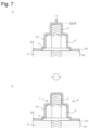
- Figure 2 shows a vertical cross-sectional view of the anticorrosion structure of the second embodiment.
- the anticorrosion structure 6a of the second embodiment has a similar structure to the anticorrosion structure 6 of the first embodiment, but is different from the anticorrosion structure 6 of the first embodiment in that an anticorrosion member 1a is provided instead of the anticorrosion member 1.
- the anticorrosion structure 6a is the same in the configuration as the anticorrosion structure 6 of the first embodiment excluding the anticorrosion member 1a, and therefore detailed description thereof is herein omitted.
- the anticorrosion member 1a is different from the anticorrosion member 1 of the first embodiment in that a coating layer 20a is formed instead of the coating layer 20.
- the coating layer 20a preferably includes an adhesion layer 22 at least on the side of the connection surface 50.
- the coating layer 20 preferably includes a base layer 21 formed of a silicone rubber, and an adhesion layer 22 formed of a silicone gel.
- the coating layer 20 is formed from, for example, a silicone adhesive sheet including the base layer 21 and the adhesion layer 22.
- a hole 7a through which the connecting part using the bolt 2 and the nut 3 can be inserted is preferably formed in the same manner as in the coating layer 20 of the first embodiment.
- the hole 7a may not be formed.
- the silicone rubber contained in the base layer 21 is the same in the configuration as the silicone rubber contained in the coating layer 20 of the first embodiment, and therefore, the detailed description thereof is herein omitted.
- the base layer 21 has a thickness of preferably 0.1 to 1.5 mm, and more preferably 0.5 to 0.8 mm.
- the adhesion layer 22 has a thickness of preferably 0.5 to 2.0 mm, and more preferably 0.8 to 1.2 mm.
- the anticorrosion member 1a is the same in the configuration as the anticorrosion member 1 of the first embodiment excluding the coating layer 20a, and therefore, the detailed description thereof is herein omitted.
- the anticorrosion structure 6a thus configured also exhibits the same effects as the anticorrosion structure 6 of the first embodiment. Since the coating layer 20a includes the adhesion layer 22 on the side of the connection surface 50, adhesion between the coating layer 20a and the connection surface 50 can be made strong, which can further improve the durability. In addition, in the anticorrosion member 1a, the main body 10 formed of the silicone rubber is attached onto the base layer 21 formed of the silicone rubber, and therefore, rigid adhesion via silicones can be obtained, which can further improve the durability.
- Figure 3 shows a flowchart of main procedures in a method for producing the anticorrosion structures according to the first and second embodiments.
- Figures 4 to 7 show diagrams for illustrating production procedures of the anticorrosion structure of the first embodiment.
- Figures 4 to 7 show views of the production procedures of the anticorrosion structure taken in the same direction as in Figure 1 .
- the method for producing an anticorrosion structure of this embodiment is an example of the method for producing the anticorrosion structure 6 of the first embodiment described above.
- the method for producing an anticorrosion structure of this embodiment includes a bolt/nut connecting step (S110), a coating layer forming step (S120), a supplying step (S130), a mold closing step (S140), a mold opening step (S150), a curing step (S160), and an excess member removing step (S170). Now, the respective steps will be described.
- the bolt/nut connecting step is a step of performing connection using the bolt 2 and the nut 3 on the connection surface 50 of the structure 5 (see Figure 4a).
- the connection using the bolt 2 and the nut 3 is performed by inserting the bolt 2 preferably in a state of the washer 4 being disposed between the connection surface 50 and the nut 3.
- the coating layer forming step is a step of forming the coating layer 20 by coating the connection surface 50 with the silicone rubber (see Figure 4b).
- the connection surface 50 is preferably coated with a silicone rubber sheet formed of a silicone rubber obtained by curing a silicone rubber compound having a plasticity number of 100 to 600.
- the hole 7 through which the connecting part of the bolt 2 and the nut 3 can be inserted is preferably formed.
- the supplying step is a step of supplying the silicone rubber compound 90 for coating the portion, protruding beyond the connection surface 50, of the connecting part using the bolt 2 and the nut 3 (see Figure 4c). More specifically, in the supplying step, the silicone rubber compound 90 having a plasticity number of 100 to 400 is supplied to the leg tip of the bolt 2.
- the silicone rubber compound 90 is preferably a semi-solid (also referred to as semicured) moisture-curable composition.
- a lump of the semi-solid silicone rubber compound is preferably supplied to the leg tip of the bolt 2.
- the portion protruding beyond the connection surface 50 is coated.
- the supply position of the semi-solid silicone rubber compound 90 is not limited to the leg tip of the bolt 2, but may be a portion excluding the leg tip of the bolt 2 in the portion protruding beyond the connection surface 50, or may be an entire outer peripheral surface of the portion protruding beyond the connection surface 50.
- the supplying step (S130) and the mold closing step (S140) correspond to an example of a coating step of the present invention.
- the mold closing step is a step of closing the mold 80 with the mold 80 set to cover the portion, protruding beyond the connection surface 50, of the connecting part of the bolt/nut connection (see Figure 5d). More specifically, in the mold closing step, the mold 80 is overlaid to cover the silicone rubber compound 90 having been supplied in the supplying step (S130), and the mold 80 is closed.
- the mold 80 is a mold covering the portion of the connecting part protruding beyond the connection surface 50.
- the mold 80 preferably has an opening 84 opened on the side of the leg tip of the bolt (see Figure 5d).
- the mold 80 preferably includes an inner mold 60 that covers the portion of the connecting part protruding beyond the connection surface 50 and is separable into two or more pieces, and an outer mold 70 covering the inner mold 60 (see Figure 6f).
- the inner mold 60 is a mold closable in the left-right direction, and includes a left mold 60a and a right mold 60b.
- the closing direction is, however, not limited to the left-right direction as in Figure 6 , but may be, for example, in the up-down direction instead of the left-right direction or in addition to the left-right direction.
- the left mold 60a includes a left main body 61a, a left recess portion 62a, and a left opening 64a.
- the right mold 60b includes a right main body 61b, a right recess portion 62b, and a right opening 64b.
- the inner mold 60 includes, through the connection between the left mold 60a and the right mold 60b, an inner main body 61, an inner recess portion 62, and an inner opening 64 (see Figure 5d).
- the inner recess portion 62 is a recess where the portion of the connecting part protruding beyond the connection surface 50 is to be disposed.
- the inner opening 64 is a region formed through the connection between the left opening 64a and the right opening 64b, and is opened on the side of the leg tip of the bolt 2, and has a through hole 65 penetrating to the inner recess portion 62.
- the outer mold 70 is one mold covering the inner mold 60, and includes an outer main body 71, an outer recess portion 72, and an outer opening 74 (see Figure 6f).
- the outer recess portion 72 is a recess in which the inner mold 60 is to be disposed.
- the outer opening 74 is an opening penetrating to the outer recess portion 72, and communicates with the through hole 65 of the inner mold 60 to form the opening 84 when the outer mold 70 is set to cover the inner mold 60 (see Figure 5d).
- the mold 80 in which the outer mold 70 is set to cover the inner mold 60 is overlaid in such a manner as to push the silicone rubber compound 90 inward, and thus, the mold 80 is closed (see Figures 5d and 5e).
- mold closing is thus performed, a gap surrounded by the inner mold 60, the bolt 2, the nut 3, and the washer 4 is formed.
- This gap is a gap for forming the anticorrosion member 1 therein, and communicates with the opening 84.
- the semi-solid silicone rubber compound 90 having been supplied to the leg tip of the bolt 2 in the supplying step (S130) is filled in the gap by the mold closing.
- the opening 84 is a portion for discharging the excess portion of the silicone rubber compound 90 not filled in the gap.
- the opening 84 is in a substantially cylindrical shape, but may be in any other shape as long as the excess portion of the silicone rubber compound 90 can be discharged thereto.
- the mold 80 is not particularly limited in the shape as long as the gap for forming the anticorrosion member 1 can be formed. In the mold closing step, the mold 80 may be closed by overlaying the inner mold 60 to push the silicone rubber compound 90 inward, and then setting the outer mold 70 to be overlaid to cover the inner mold 60.
- the mold opening step is a step of opening the mold 80 (see Figure 6f). More specifically, in the mold opening step, the outer mold 70 is first removed, and then the inner mold 60 is opened in the left-right direction. At this point, the silicone rubber compound 90 covering the outer circumferences of the bolt 2 and the nut 3 is in a semi-solid state. In this embodiment, since the silicone rubber compound 90 has a plasticity number of 100 to 400, the silicone rubber compound 90 can be inhibited from deforming under its own weight even if the mold 80 is opened when it is in the semi-solid state before curing.
- the curing step is a step of curing the silicone rubber compound (see Figure 7g).
- the silicone rubber compound 90 coating the portion protruding beyond the connection surface 50 in the supplying step (S130) and the mold closing step (S140) is preferably cured.
- Curing conditions vary depending on the type of the silicone rubber compound. For example, when an addition-curing type curable organopolysiloxane composition is used, the curing step is performed at preferably 80 to 150°C, and more preferably 90 to 120°C.
- the curing step may be performed, further as post curing, at a higher temperature of preferably 180 to 250°C, and more preferably 190 to 220°C.
- the curing step can be performed at room temperature (20 to 30°C).
- the curing step is usually performed at room temperature (20 to 30°C).
- the silicone rubber can be obtained by irradiating the inside of the mold 80 holding the mixture therein with UV or electron beam.
- the main body 10 and the coating layer 20 of the anticorrosion member 1, and an excess member 11 are formed.
- the excess member 11 is a member formed of the excess portion of the silicone rubber compound 90 not filled in the gap surrounded by the inner mold 60, the bolt 2, the nut 3, and the washer 4, and is a member protruding from the main body 10 toward the opening 84.
- the excess member removing step is a step of removing the excess member 11 (see Figures 7g and 7h).
- the excess member 11 may be mechanically cut, or the excess member 11 may be removed by polishing the surface thereof.
- the anticorrosion structure 6 produced in this manner is formed of the silicone rubber excellent in heat resistance, water resistance, weather resistance, electrical insulation and the like, and further has the connection surface 50 coated with the coating layer 20, and therefore, durability of the anticorrosion effect can be improved. Besides, since the silicone rubber compound having a plasticity number of 100 to 400 is used, the silicone rubber compound can be inhibited from deforming under its own weight. Accordingly, the mold 80 can be opened when the silicone rubber compound is in a semi-solid state before curing, and thus the production of another anticorrosion structure 6 can be started with the mold 80, and therefore, there is no need to use a large number of molds 80, and working time can be reduced.
- Figures 8 to 11 show diagrams for illustrating production procedures of the anticorrosion structure of the second embodiment. It is noted that Figures 8 to 11 show views of the production procedures of the anticorrosion structure taken in the same direction as in Figure 2 .
- the production method of this embodiment is an example of a method for producing the anticorrosion structure 6a of the second embodiment described above.
- the method for producing an anticorrosion structure of this embodiment is different from the production method of the first embodiment in that the coating layer 20a is formed instead of the coating layer 20, but is the same as the production method of the first embodiment in the other configurations and the procedures of the production method.
- the method for producing an anticorrosion structure of this embodiment includes, in the same manner as in the first embodiment, the bolt/nut connecting step (S110), the coating layer forming step (S120), the supplying step (S130), the mold closing step (S140), the mold opening step (S150), the curing step (S160), and the excess member removing step (S170) (see Figure 3 ).
- the bolt/nut connecting step (S110) is performed in the same manner as in the first embodiment.
- the coating layer 20a coating the connection surface 50 is formed with a silicone rubber sheet including the adhesion layer 22 (see Figure 8i).
- the coating layer 20a is preferably formed by adhering, onto the connection surface 50, a silicone adhesive sheet composed of the base layer 21 and the adhesion layer 22 with the adhesion layer 22 disposed on the side of the connection surface 50.
- the hole 7a through which the connecting part of the bolt 2 and the nut 3 can be inserted is preferably formed in the same manner as in the silicone rubber sheet used for forming the coating layer 20 of the first embodiment.
- the supplying step (S130), the mold closing step (S140), the mold opening step (S150), the curing step (S160), and the excess member removing step (S170) are executed to produce the anticorrosion structure 6a (see Figures 8j, 9 , 10 and 11 ).
- the durability of the anticorrosion effect can be improved in the same manner as in the anticorrosion structure 6.
- the silicone rubber compound having a plasticity number of 100 to 400 is used, the mold 80 can be opened when the silicone rubber compound is in a semi-solid state before curing, and therefore, there is no need to use a large number of molds 80, and working time can be reduced.
- the coating layer 20a can be easily formed by adhering the silicone adhesive sheet onto the connection surface 50, and therefore, the durability can be further improved.
- Figure 12 shows a flowchart of main procedures in a method for producing an anticorrosion structure according to the third embodiment and a fourth embodiment.
- Figures 13 to 16 show diagrams for illustrating production procedures of an anticorrosion structure of the third embodiment.
- Figures 13 to 16 show views of the production procedures of the anticorrosion structure taken in the same direction as in Figure 1 .
- the method for producing an anticorrosion structure of this embodiment is an example of the method for producing the anticorrosion structure 6 of the first embodiment described above.
- the method for producing an anticorrosion structure of this embodiment includes the bolt/nut connecting step (S110), the coating layer forming step (S120), the mold closing step (S140), a supplying step (S230), a curing step (S260), the mold opening step (S150), and the excess member removing step (S170).
- the method for producing an anticorrosion structure of this embodiment is different from the production method of the first embodiment described above in that the supplying step (S230) is executed instead of the supplying step (S130) after the mold closing step (S140), and that the curing step (S260) is executed instead of the curing step (S160) before the mold opening step (S150), and is the same as the production method of the first embodiment in the other configurations and procedures of the production method.
- the bolt/nut connecting step (S110) and the coating layer forming step (S120) are executed (see Figures 13a and 13b).
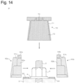
- the mold closing step (S140) the mold 80 described above is set to cover the portion, protruding beyond the connection surface 50, of the connecting part of the bolt/nut connection, and the mold is closed (see Figure 14p).
- the inner mold 60 is first overlaid to cover the portion protruding beyond the connection surface 50, and the outer mold 70 is then overlaid to cover the inner mold 60, and thus, the mold 80 is set.
- the mold 80 in which the outer mold 70 is set to cover the inner mold 60 may be overlaid on the portion protruding beyond the connection surface 50 to be closed in the same manner as in the first embodiment described above.
- the mold 80 preferably has the opening 84 opened on the side of the leg tip of the bolt (see Figure 15q).
- the opening 84 is a supply port (gate) through which the silicone rubber compound 90 to be formed into the main body 10 of the anticorrosion member 1 after curing is supplied into the mold 80 (inner mold 60).
- the opening 84 is in a substantially cylindrical shape, but may be in any other shape as long as the silicone rubber compound 90 can be supplied into the mold 80 (inner mold 60) with a piston 86 described below.
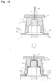
- the supplying step (S230) is a step of covering the portion, protruding beyond the connection surface 50, of the connecting part using the bolt 2 and the nut 3 with the silicone rubber compound 90 (see Figures 15q and 15r).
- the silicone rubber compound 90 is preferably a liquid silicone rubber.
- the portion protruding beyond the connection surface 50 is coated with the silicone rubber compound 90 preferably with a pushing jig including the mold 80 described above, and the piston 86 for pushing the silicone rubber compound 90 in through the opening 84 of the mold 80.
- the silicone rubber compound 90 is set at the leg tip of the bolt 2 (corresponding to the opening 84 in this embodiment), and an end of the piston 86 is applied to the silicone rubber compound 90 to push the silicone rubber compound 90 through the opening 84 toward the connection surface 50. Since the gap surrounded by the inner mold 60, the bolt 2, the nut 3 and the washer 4 communicates with the opening 84, the silicone rubber compound 90 can be supplied into the gap through the opening 84. In this manner, the silicone rubber compound 90 is filled in the gap, and the portion of the connecting part protruding beyond the connection surface 50 is coated with the silicone rubber compound 90.
- the piston 86 is not particularly limited as long as at least it is in a shape capable of pushing the silicone rubber compound into the gap formed in the mold 80.
- the mold closing step (S140) and the supplying step (S230) correspond to an example of the coating step of the present invention.
- the curing step is a step of curing the silicone rubber compound 90 (see Figure 16s).
- the silicone rubber compound 90 having been supplied in the supplying step (S230) is cured in a state of the mold 80 being set.
- the mold opening step (S150) and the excess member removing step (S170) are executed, and thus, the anticorrosion structure 6 is produced (see Figures 16g and 16h).
- the excess member 11 formed in the curing step (S260) corresponds to a portion protruding from the main body 10 toward the opening 84, and is designated also as a gate member or a gate mark.
- the durability of the anticorrosion effect can be improved in the same manner as in the anticorrosion structures 6 and 6a produced by the production methods of the above-described embodiments.
- Figures 17 to 20 show diagrams for illustrating production procedures of an anticorrosion structure according to the fourth embodiment.
- Figures 17 to 20 show views of the production procedures of the anticorrosion structure taken in the same direction as in Figure 2 .
- the production method of this embodiment is an example of the method for producing the anticorrosion structure 6a of the second embodiment described above.
- the method for producing an anticorrosion structure of this embodiment is different from the production method of the third embodiment in that the coating layer 20a is formed instead of the coating layer 20, and is the same as the production method of the third embodiment in the other configurations and the procedures of the production method.
- the method for producing an anticorrosion structure of this embodiment includes, in the same manner as in the third embodiment, the bolt/nut connecting step (S110), the coating layer forming step (S120), the mold closing step (S140), the supplying step (S230), the curing step (S260), the mold opening step (S150), and the excess member removing step (S170) (see Figure 12 ).
- the bolt/nut connecting step (S110) is executed (see Figure 17a), and the coating layer 20a is formed in the coating layer forming step (S120) (see Figure 17i).
- the mold closing step (S140), the supplying step (S230), and the curing step (S260) are executed (see Figures 18 , 19 and 20w).
- the mold opening step (S150) and the excess member removing step (S170) are executed, and thus, the anticorrosion structure 6a is produced (see Figures 20n and 20o).
- the durability of the anticorrosion effect can be improved in the same manner as in the anticorrosion structures 6 and 6a produced by the production methods of the above-described embodiments.
- the coating layer 20a can be easily formed by adhering a silicone adhesive sheet onto the connection surface 50, and thus, the durability can be further improved.
- the anticorrosion member 1 or 1a includes the coating layer 20 or 20a in the anticorrosion structure 6 or 6a, but the coating layer 20 or 20a may not be included. In other words, the anticorrosion member 1 or 1a may include the main body 10 alone.
- the leg portion of the bolt 2 and the nut 3 protruding beyond the connection surface 50 of the structure 5 are coated, but a head portion of the bolt 2 may be coated in addition to the leg portion of the bolt 2 and the nut 3.
- the connecting part using the bolt 2 and the nut 3 is coated, but a connecting part including at least one of the bolt 2 and the nut 3 may be coated.
- the anticorrosion structure 6 or 6a may include the anticorrosion member 1 or 1a on the bolt 2 and the nut 3, on the bolt 2 alone, or on the nut 3 alone.
- the coating layer forming step (S120) is executed after executing the bolt/nut connecting step (S110), but the bolt/nut connecting step (S110) may be executed after executing the coating layer forming step (S120).
- the coating layer 20 or 20a may be formed in a region on the connection surface 50 excluding the hole. In this case, the coating layer 20 or 20a may be formed between the washer 4 and the connection surface 50.
- the present invention is applicable to bolts and nuts used in, for example, various building structures such as bridges, iron towers, buildings, factories, and houses, construction machines, and processing machines.
Landscapes
- Chemical & Material Sciences (AREA)
- Organic Chemistry (AREA)
- Engineering & Computer Science (AREA)
- Chemical Kinetics & Catalysis (AREA)
- General Engineering & Computer Science (AREA)
- Polymers & Plastics (AREA)
- Health & Medical Sciences (AREA)
- Medicinal Chemistry (AREA)
- Mechanical Engineering (AREA)
- Materials Engineering (AREA)
- Wood Science & Technology (AREA)
- Life Sciences & Earth Sciences (AREA)
- Metallurgy (AREA)
- Laminated Bodies (AREA)
- Preventing Corrosion Or Incrustation Of Metals (AREA)
- Suspension Of Electric Lines Or Cables (AREA)
Abstract
Description
- The present application claims priority based on
Japanese Patent Application No. 2020-118259 filed in Japan on July 9, 2020 - The present invention relates to an anticorrosion structure and a method for producing the same.
- In various structures, a method for connecting members to each other with a bolt and a nut has been conventionally employed. In general, when a bolt and a nut are connected to each other, a screw portion of the bolt and the nut protrude beyond a connection surface and hence are likely to be exposed to the weather, which causes a problem of easy rusting. As anticorrosion means for bolts and nuts, a method employing anticorrosion coating of bolts and nuts is performed. Since bolts and nuts have, however, complicated structures, there arises a problem that the anticorrosion effect is lost in a short period of time because rainwater having entered through a gap is not easily drained. Therefore, as anticorrosion means for bolts and nuts to be employed instead of the anticorrosion coating, a method of coating a connecting part between a bolt and a nut with a resin anticorrosion member (cap) is known (see, for example,
Patent Literature 1 and Patent Literature 2). -
- Patent Literature 1:
Japanese Patent Laid-Open No. 2-138488 - Patent Literature 2:
Japanese Patent Laid-Open No. 2002-227819 - Many of such anticorrosion members are generally produced using a resin such as vinyl chloride or an epoxy resin. Therefore, in an anticorrosion structure including the above-described anticorrosion member in a connecting part using at least one of a metal bolt and a metal nut, the anticorrosion member may be cracked or cleaved, or the anticorrosion member may be lifted due to aging, and if the anticorrosion member is left as it is, the anticorrosion effect might be degraded. Accordingly, there is a demand for an anticorrosion structure having a high anticorrosion effect.
- The present invention was devised in consideration of the above-described problems, and an object is to provide an anticorrosion structure having a high anticorrosion effect, and a method for producing the same.
-
- (1) An anticorrosion structure according to one embodiment for achieving the above-described object, comprises at least one of a metal bolt and a metal nut, and an anticorrosion member coating a portion, protruding beyond a connection surface, of a connecting part using at least one of the bolt and the nut, wherein the anticorrosion member is formed of a silicone rubber obtained by curing a silicone rubber compound.
- (2) In the anticorrosion structure according to another embodiment, the anticorrosion member may preferably include a coating layer that is formed of a silicone rubber and coats the connection surface.
- (3) In the anticorrosion structure according to another embodiment, the coating layer may preferably include an adhesion layer at least on a side of the connection surface.
- (4) In the anticorrosion structure according to another embodiment, the coating layer may be preferably formed of the silicone rubber obtained by curing a silicone rubber compound having a plasticity number of 100 to 600.
- (5) In the anticorrosion structure according to another embodiment, the anticorrosion member may be preferably formed of the silicone rubber obtained by curing the silicone rubber compound having a plasticity number of 100 to 400.
- (6) A method for producing an anticorrosion structure according to one embodiment is a method for producing any one of the anticorrosion structures described above, and comprises: a coating step of, with a silicone rubber compound, coating a portion, protruding beyond a connection surface, of a connecting part using at least one of a metal bolt and a metal nut; and a curing step of curing the silicone rubber compound.
- (7) In the method for producing the anticorrosion structure according to another embodiment, in the coating step, the portion of the connecting part protruding beyond the connection surface may be coated with the silicone rubber compound by overlaying a mold to cover the portion of the connecting part protruding beyond the connection surface in a state of the silicone rubber compound being supplied to the portion of the connecting part protruding beyond the connection surface.
- (8) In the method for producing the anticorrosion structure according to another embodiment, in the coating step, the mold preferably may include an inner mold that covers the portion of the connecting part protruding beyond the connection surface, and is separable into two or more pieces, and an outer mold covering the inner mold.
- (9) The method for producing the anticorrosion structure according to another embodiment may preferably further comprise a coating layer forming step of forming a coating layer by coating the connection surface with a silicone rubber.
- (12) In the method for producing the anticorrosion structure according to another embodiment, in the coating layer forming step, the coating layer may be preferably formed by coating the connection surface with a silicone rubber sheet including an adhesion layer in such a manner as to have the adhesion layer at least on a side of the connection surface.
- According to the present invention, an anticorrosion structure having a high anticorrosion effect and a method for producing the same can be provided.
-
- [
Figure 1] Figure 1 shows a vertical cross-sectional view of an anticorrosion structure according to a first embodiment. - [
Figure 2] Figure 2 shows a vertical cross-sectional view of an anticorrosion structure according to a second embodiment. - [
Figure 3] Figure 3 shows a flowchart of main procedures in a method for producing the anticorrosion structures according to the first and second embodiment. - [
Figure 4] Figure 4 shows a diagram for illustrating production procedures of the anticorrosion structure of the first embodiment. - [
Figure 5] Figure 5 shows a diagram for illustrating production procedures of the anticorrosion structure of the first embodiment. - [
Figure 6] Figure 6 shows a diagram for illustrating production procedures of the anticorrosion structure of the first embodiment. - [
Figure 7] Figure 7 shows a diagram for illustrating production procedures of the anticorrosion structure of the first embodiment. - [
Figure 8] Figure 8 shows a diagram for illustrating production procedures of the anticorrosion structure of the second embodiment. - [
Figure 9] Figure 9 shows a diagram for illustrating production procedures of the anticorrosion structure of the second embodiment. - [
Figure 10] Figure 10 shows a diagram for illustrating production procedures of the anticorrosion structure of the second embodiment. - [
Figure 11] Figure 11 shows a diagram for illustrating production procedures of the anticorrosion structure of the second embodiment. - [
Figure 12] Figure 12 shows a flowchart of main procedures in a method for producing an anticorrosion structure according to a third embodiment and a fourth embodiment. - [
Figure 13] Figure 13 shows a diagram for illustrating production procedures of the anticorrosion structure of the third embodiment. - [
Figure 14] Figure 14 shows a diagram for illustrating production procedures of the anticorrosion structure of the third embodiment. - [
Figure 15] Figure 15 shows a diagram for illustrating production procedures of the anticorrosion structure of the third embodiment. - [
Figure 16] Figure 16 shows a diagram for illustrating production procedures of the anticorrosion structure of the third embodiment. - [
Figure 17] Figure 17 shows a diagram for illustrating production procedures of the anticorrosion structure of the fourth embodiment. - [
Figure 18] Figure 18 shows a diagram for illustrating production procedures of the anticorrosion structure of the fourth embodiment. - [
Figure 19] Figure 19 shows a diagram for illustrating production procedures of the anticorrosion structure of the fourth embodiment. - [
Figure 20] Figure 20 shows a diagram for illustrating production procedures of the anticorrosion structure of the fourth embodiment. - 1, 1a ... anticorrosion member, 2 ... bolt, 3 ... nut, 6, 6a ... anticorrosion structure, 20, 20a ... coating layer, 22 ... adhesion layer, 50 ... connection surface, 60 ... inner mold, 70 ... outer mold, 80 ... mold, 84 ... opening, 86 ... piston
- Preferred embodiments of the present invention will now be described with reference to the accompanying drawings. The embodiments described below do not limit the claimed invention. All of elements and combinations thereof described in the embodiments are not necessarily essential for solution by the present invention.
-
Figure 1 shows a vertical cross-sectional view of an anticorrosion structure according to a first embodiment. Here, the term "vertical cross-sectional view" means a view obtained by vertically cutting the structure in a direction from a volt leg toward a nut. The same applies to the other embodiments described below. - An anticorrosion structure 6 according to this embodiment includes at least one of a metal bolt 2 and a metal nut 3, and an
anticorrosion member 1 coating a portion, protruding beyond aconnection surface 50, of a connecting part using the at least one of the bolt 2 and the nut 3. Here, the term "metal" means a metal not particularly limited such as iron or an iron-based alloy (including SUS). Theanticorrosion member 1 includes amain body 10 formed of a silicone rubber obtained by curing a silicone rubber compound. Theanticorrosion member 1 also includes acoating layer 20 preferably formed of a silicone rubber for coating theconnection surface 50. In this embodiment, theanticorrosion member 1 coats the portion, protruding beyond theconnection surface 50, of the connecting part using the bolt 2 and the nut 3 connected to a structure 5. Now, constituent elements of theanticorrosion member 1 provided in the anticorrosion structure 6 will be described in detail. - The
main body 10 is a member for coating the portion, protruding beyond theconnection surface 50, of the connecting part using the bolt 2 and the nut 3. Themain body 10 includes a recess 12 where the portion of the connecting part protruding beyond theconnection surface 50 is disposed. Themain body 10 includes, for example, a head portion 10a coating a screw portion (leg portion) of the bolt 2 protruding beyond the nut 3, a trunk portion 10b coating a side surface portion of the nut 3, and a flange portion 10c coating a washer 4 disposed between the nut 3 and theconnection surface 50. Themain body 10 is preferably configured in a shape according to the shape of the member to be disposed in the recess 12 (such as the screw portion of the bolt 2, the nut 3, and the washer 4). The shapes of themain body 10 and the recess 12 are not limited to the shapes illustrated inFigure 1 , but are preferably appropriately designed according to the shape of the member to be disposed in the recess 12. For example, if the washer 4 is not used in the connecting part, the flange portion 10c may not be provided. - The silicone rubber is a rubber-like elastic body having a siloxane bond (-Si-O-Si) as a main skeleton. A silicone rubber usable in this embodiment may be obtained by any of curing types such as addition curing type, condensation reaction type, UV curing type, and electron beam curing type, and is preferably an addition-curing type silicone rubber in particular. The silicone rubber is a rubber-like elastic body obtained by curing a curable organopolysiloxane composition containing an organopolysiloxane as a main agent (silicone rubber compound). Here, the term "main agent" means an agent having a largest mass ratio among components contained in the curable organopolysiloxane composition. The organopolysiloxane is contained in the curable organopolysiloxane composition preferably in an amount of 50% by mass or more, and the amount may be less than 50% by mass as far as it is the main agent. Now, as the silicone rubber compound used as a raw material before curing the silicone rubber, examples of addition-curing type and condensation curing type curable organopolysiloxane compositions will be described.
- The addition-curing type curable organopolysiloxane composition may be designated as an addition-curing type curable silicone composition or an addition-curing type curable silicone rubber composition. The addition-curing type curable organopolysiloxane composition can be mainly formed of, for example, the following components:
- An organopolysiloxane is a main agent of the addition-curing type curable organopolysiloxane composition, and has an average of two or more alkenyl groups per molecule. The organopolysiloxane is a base polymer of the addition-curing type curable organopolysiloxane composition, and is represented by the following average composition formula (I):
R3 aSiO(4-a)/2 ... (I)
- In the formula (I), R3 is the same or different unsubstituted or substituted monovalent hydrocarbon group having 1 to 12, preferably 1 to 10, and more preferably 1 to 8 carbon atoms, and a is a positive number in a range of 1.5 to 2.8, preferably 1.8 to 2.5, and more preferably 1.95 to 2.05.
- Examples of the alkenyl group include vinyl groups, allyl groups, butenyl groups, pentenyl groups, hexenyl groups and heptenyl groups. Among them, vinyl groups are preferably used. Examples of the organic group bonded to silicon atoms, other than alkenyl groups, in this component include alkyl groups (methyl group, ethyl group, propyl group, butyl group, pentyl group, hexyl group and the like), aryl groups (phenyl group, tolyl group, xylyl group and the like), and alkyl halide groups (3-chloropropyl group, 3,3,3-trifluoropropyl group and the like). Among them, a methyl group is preferably used. Examples of the molecular structure of this component include straight-chain structures, partially branched straight-chain structures, branched-chain structures, network structures and dendritic structures.
- As the organopolysiloxane of this component, for example, polydimethylsiloxanes blocked with a dimethylvinylsiloxy group at both terminals of the molecular chain, copolymers of dimethylsiloxanes blocked with a dimethylvinylsiloxy group at both terminals of the molecular chain and methylvinylsiloxanes, copolymers of dimethylsiloxanes blocked with a trimethylsiloxy group at both terminals of the molecular chain and methylvinylsiloxanes, organopolysiloxanes including a siloxane unit represented by (CH3)3SiO1/2, a siloxane unit represented by (CH3)2(CH2=CH)SiO1/2 and a siloxane unit represented by SiO4/2, such organopolysiloxanes in which some of methyl groups are replaced with a substituent selected from alkyl groups (ethyl group, propyl group and the like), aryl groups (phenyl group, tolyl group and the like) and alkyl halide groups (3,3,3-trifluoropropyl group and the like), such organopolysiloxanes in which some of vinyl groups are replaced with an alkenyl group (allyl group, propenyl group or the like), and mixtures of two or more of these organopolysiloxanes can be used.
- A hydrogenated organopolysiloxane acts as a curing agent for the addition-curable type curable organopolysiloxane composition, and has an average of two or more hydrogens bonded to silicon atoms per molecule. The hydrogenated organopolysiloxane is designated also as an organohydrogen polysiloxane. The hydrogenated organopolysiloxane is represented by the following average composition formula (II), and one having at least 2, preferably 3 or more, more preferably 3 to 100, and further preferably 4 to 50 hydrogen atoms bonded silicon atoms (SiH groups) per molecule is suitably used.
R4 bHcSiO(4-b-c)/2 ... (II)
- In the formula (II), R4 is the same or different unsubstituted or substituted monovalent hydrocarbon group having 1 to 12, preferably 1 to 10, and more preferably 1 to 8 carbon atoms. b is 0.7 to 2.1, c is 0.001 to 1.0, and b + c is a positive number of 0.8 to 3.0.
- Examples of the organic group bonded to silicon in this component include alkyl groups (methyl group, ethyl group, propyl group, butyl group, pentyl group, hexyl group and the like), aryl groups (phenyl group, tolyl group, xylyl group and the like), and alkyl halide groups (3-chloropropyl group, 3,3,3-trifluoropropyl group and the like). Among them, a methyl group is preferably used. Examples of the molecular structure of this component include straight-chain structures, partially branched straight-chain structures, branched-chain structures, network structures and dendritic structures.
- As the hydrogenated organopolysiloxane of this component, for example, polydimethylsiloxanes blocked with a dimethylhydrogensiloxy group at both terminals of the molecular chain, polymethylhydrogensiloxanes blocked with a trimethylsiloxy group at both terminals of the molecular chain, copolymers of dimethylsiloxanes blocked with a trimethylsiloxy at both terminals of the molecular chain and methylhydrogensiloxanes, cyclic polymethylhydrogensiloxanes, organopolysiloxanes including a siloxane unit represented by (CH3)2HSiO1/2 and a siloxane unit represented by SiO4/2, such organopolysiloxanes in which some of methyl groups are replaced with a alkyl group (ethyl group, propyl group or the like), an aryl group (phenyl group, tolyl group or the like) or an alkyl halide group (3,3,3-trifluoropropyl group or the like), and mixtures of two or more of these organopolysiloxanes can be used. Among them, mixtures of organopolysiloxanes, which have hydrogen atoms bonded to silicon atoms, only at both terminals of the molecular chain and organopolysiloxanes, which have a silicon atom bond, on the side chain of the molecular chain are preferably used for enhancing mechanical properties (especially elongation) of cured products to be obtained.
- The content of this component in the addition-curable type curable organopolysiloxane composition is such that the molar ratio of hydrogen atoms bonded to silicon atoms in this component to alkenyl groups in the component (2-1-1) is within the range of 0.01 to 20, preferably within the range of 0.1 to 10, further preferably within the range of 0.1 to 5.
The reason why the content is set within the above-described range is that when the content of this component is not below the lower limit of the range, the silicone rubber tends to be easily sufficiently cured, and when the content of this component is not above the upper limit of the range, a resultant cured adhesive sheet tends to have higher mechanical properties. When a mixture of an organopolysiloxane, which has hydrogen atoms bonded to silicon atoms, only at both terminals of the molecular chain and an organopolysiloxane, which has a silicon atom bond, on the side chain of the molecular chain is used as this component, the content of the former organopolysiloxane is such that the molar ratio of hydrogen atoms bonded to silicon atoms in this component to alkenyl groups in the component (2-1-1) is preferably within the range of 0.01 to 10, further preferably within the range of 0.1 to 10, furthermore preferably within the range of 0.1 to 5. The content of the latter organopolysiloxane is such that the molar ratio of hydrogen atoms bonded to silicon atoms in this component to alkenyl groups in the component (2-1-1) is preferably within the range of 0.5 to 20, further preferably within the range of 0.5 to 10, furthermore preferably within the range of 0.5 to 5. - A curing catalyst is not essential, and preferred examples thereof include platinum-based catalysts for hydrosilylation reaction. Examples of the platinum-based catalyst for hydrosilylation reaction include platinum fine powder, platinum black, platinic chloride, alcohol-modified platinic chloride, complexes of platinum and diketone, complexes of platinic chloride and olefins, complexes of platinum chloride and alkenylsiloxanes, and such catalysts supported on carriers (alumina, silica, carbon black and the like). Among them, complexes of platinic chloride and alkenylsiloxanes are preferably used because of high catalytic activity. Complexes of platinic chloride and divinyltetramethyldisiloxane are further preferably used. The amount of this component blended is preferably within the range of 1 to 1000 parts by mass, further preferably within the range of 1 to 100 parts by mass, in terms of platinum metal atoms, based on 1,000,000 parts by mass of the component (2-1-1).
- It is preferable to add a filler for enhancing the mechanical strength of the addition-curable type curable organopolysiloxane composition, and the filler may be a known compound that is commonly used for formulation of silicone rubber. Examples of this component include fumed silica, precipitated silica, fired silica, ground quartz, and such silica powder whose surface has been treated with an organosilicon compound (organoalkoxysilane, organohalosilane, organosilazane or the like). It is preferable that in particular, a silica powder having a BET specific surface area of 50 m2/g or more be used as this component for sufficiently enhancing the mechanical strength of the cured material.
- Addition of this component is optional in the addition-curable type curable organopolysiloxane composition, but for enhancing the mechanical strength of the cured silicone rubber, the amount of this component blended is preferably within the range of 1 to 1000 parts by mass, further preferably within the range of 1 to 400 parts by mass, based on 100 parts by mass of the component (2-1-1). Further, the addition-curable type curable organopolysiloxane composition may contain other optional components, for example inorganic and organic fillers such as fumed titanium oxide, diatomaceous earth, iron oxide, aluminum oxide, aluminosilicate, calcium carbonate, zinc oxide and aluminum hydroxide. The addition-curable type curable organopolysiloxane composition may contain such fillers whose surfaces have been treated with the organosilicon compound. The amount of the filler blended can be selected according to the purpose and the type of filler, but is within the range of 1 to 90% by volume, preferably within the range of 5 to 60% by volume, based on the amount of the component (2-1-1).
- The addition-curing type curable organopolysiloxane composition preferably further contains, for adjusting the curability thereof, acetylene-based compounds (3-methyl-1-buten-3-ol, 3,5-dimethyl-1-hexyn-3-ol, 3-phenyl-1-butyn-3-ol and the like), enyne compounds (3-methyl-3-penten-1-yne, 3,5-dimethyl-3-hexen-1-yne and the like), organosiloxane compounds having vinyl groups in an amount of 5% by mass or more per molecule (1,3,5,7-tetramethyl-1,3,5,7-tetravinylcyclotetrasiloxane, 1,3,5,7-tetramethyl-1,3,5,7-tetrahexenylcyclotetrasiloxane, methylvinylsiloxanes blocked with a silanol group at both terminals of the molecular chain, copolymers of methylvinylsiloxanes blocked with a silanol group at both terminals of the molecular chain and dimethylsiloxanes, and the like), or other curing controlling agents (triazoles such as benzotriazole, phosphines, mercaptans, hydrazines and the like). The content of these compounds is not limited, but is preferably within the range of 0.001 to 5 parts by mass based on 100 parts by mass of the component (2-1-1).
- The method for preparing the addition-curable type curable organopolysiloxane composition is not limited, and the addition-curable self-adhesive silicone rubber can be prepared by mixing other optional components if necessary, but it is preferable that to a base compound prepared by heating and mixing the components (2-1-1) and (2-1-3) beforehand, other components be added. When adding the other optional components, these components may be added at the time of preparing the base compound, and if the other optional components are degenerated by heating and mixing, these components may be added at the time of adding the components (2-1-2) and (2-1-4). Further, at the time of preparing the base compound, the organic silicon compound may be added to treat the surface of the component (2-1-3) in situ.
- The condensation reaction type curable silicone rubber composition can be mainly formed of, for example, the following components:
- An organopolysiloxane is a main agent component of the condensation reaction type curable silicone rubber composition, and is preferably a diorganopolysiloxane represented by the following chemical formula (1) or chemical formula (2). The chemical formula may be designated as an average composition formula.


- In the chemical formulae (1) and (2), R is a monovalent hydrocarbon group. R may be one or more hydrocarbon groups selected from alkyl groups (methyl group, ethyl group, propyl group, butyl group, 2-ethylbutyl group, octyl group and the like), cycloalkyl groups (cyclohexyl group, cyclopentyl group and the like), alkenyl groups (vinyl group, propenyl group, butenyl group, heptenyl group, hexenyl group, allyl group and the like), aryl groups (phenyl group, tolyl group, xylyl group, naphthyl group, diphenyl group and the like), aralkyl groups (benzyl group, phenylethyl group and the like), and groups formed by replacing at least some of hydrogen atoms bonded to carbon atoms of each of the above hydrocarbon groups with halogens, cyano groups or the like (chloromethyl group, trifluoropropyl group, 2-cyanoethyl group, 3-cyanopropyl group and the like). The number of carbon atoms in R is preferably 1 to 12, further preferably 1 to 10. In the chemical formulae (1) and (2), A is an oxygen atom or a polymethylene group (including a methylene group) represented by -(CH2)m- (m is 1 to 8). A is preferably an oxygen atom or an ethylene group.
- In the chemical formulae (1) and (2), n is any number at which the dynamic viscosity of the component (2-1-6) at 25°C is within the range of 100 to 1000000 cm2/s. The dynamic viscosity is further preferably within the range of 500 to 500000 cm2/s.
- In the chemical formulae (1) and (2), B is a hydrolysable group. Examples of the group B include alkoxy groups (methoxy group, ethoxy group, propoxy group, butoxy group and the like), ketoxime groups (dimethylketoxime group, methylethylketoxime group and the like), acyloxy groups (acetoxy group and the like) and alkenyloxy groups (isopropenyloxy group, isobutenyloxy group and the like). In the chemical formulae (1) and (2), x is 2 or 3.
- The component (2-1-6) can be produced by a known method (for example, an equilibrium reaction method using a cyclic siloxane or linear oligomer and an acid catalyst or base catalyst).
- When a branched structure is introduced into the diorganopolysiloxane used as the component (2-1-6), it is possible to use, as an ordinary method, a method in which a silane or siloxane containing at least one of a SiO3/2 unit and a SiO4/2 unit is added during polymerization in such a manner that the diorganopolysiloxane does not turn into a gel. It is preferable to use the component (2-1-6) after removing low-molecular siloxanes by washing or the like for reducing contamination.
- As a crosslinker, a silane having two or more, preferably three or more hydrolysable groups per molecule, or a partially hydrolyzed and condensed product of the silane is used. Examples of the hydrolysable group include alkoxy groups (methoxy group, ethoxy group, butoxy group and the like), ketoxime groups (dimethylketoxime group, methylethylketoxime group and the like), acyloxy groups (acetoxy group and the like), alkenyloxy groups (isopropenyloxy group, isobutenyloxy group and the like), amino groups (N-butylamino group, N,N-diethylamino group and the like) and amide groups (N-methylacetamide group and the like). Among them, alkoxy groups, ketoxime groups, acyloxy groups and alkenyloxy groups are preferable. The amount of the crosslinker blended is preferably within the range of 1 to 50 parts by mass, further preferably within the range of 2 to 30 parts by mass, and furthermore preferably within the range of 5 to 20 parts by mass, based on 100 parts by mass of the component (2-1-6).
- A curing catalyst is not essential, but use of a curing catalyst can accelerate curing of the curable silicone rubber composition. Examples of the curing catalyst include alkyltin ester compounds (dibutyltin diacetate, dibutyltin dilaurate, dibutyltin dioctoate and the like), titanic acid esters or titanium chelate compounds (tetraisopropoxy titanium, tetra-n-butoxy titanium, tetrakis(2-ethylhexoxy)titanium, dipropoxybis(acetylacetona)titanium, titanium isopropoxyoctylene glycol and the like), other appropriate organometal compounds (zinc naphthenate, zinc stearate, zinc 2-ethyloctoate, iron 2-ethylhexoate, cobalt 2-ethylhexoate, manganese 2-ethylhexoate, cobalt naphthenate, alkoxyaluminum compounds and the like), aminoalkyl group-substituted alkoxysilanes (3-aminopropyltriethoxysilane, N-β(aminoethyl)γ-aminopropyltrimethoxysilane and the like), amine compounds or salts thereof (hexylamine, dodecylamine phosphate and the like), quaternary ammonium salts (benzyltriethylammonium acetate and the like), lower fatty acid salts of alkali metals (lower fatty acid salts of alkali metals of potassium acetate, sodium acetate, lithium oxalate and the like), dialkylhydroxylamines (dimethylhydroxylamine, diethylhydroxylamine and the like), and silanes or siloxanes having a guanidyl group (tetramethylguanidylpropyltrimethoxysilane, tetramethylguanidylpropylmethyldimethoxysilane, tetramethylguanidylpropyltris(trimethylsiloxy)silane and the like). One of these compounds, or a mixture of two or more of these compounds may be used. The amount of the curing catalyst blended is preferably within the range of 0 to 20 parts by mass, further preferably within the range of 0.001 to 10 parts by mass, and furthermore preferably within the range of 0.01 to 5 parts by mass, based on 100 parts by mass of the component (2-1-6).
- A filler is not essential, but can be suitably used for reinforcement or the like. Examples of the filler include reinforcing agents (fumed silica, precipitated silica, such silica whose surface has been hydrophobized with an organosilicon compound, quartz powder, talc, zeolite, bentonite and the like), fibrous fillers (asbestos, glass fibers, organic fibers and the like), and basic fillers (calcium carbonate, zinc carbonate, zinc oxide, magnesium oxide, celite and the like). Among them, silica, calcium carbonate and zeolite are preferably used, and fumed silica having a hydrophobized surface, and calcium carbonate are further preferably used. The amount of the filler blended can be selected according to the purpose and the type of filler, and is within the range of 1 to 90% by volume, and preferably within the range of 5 to 60% by volume, based on the amount of the component (2-1-6).
- An adhesiveness-imparting component is not essential, but can be suitably used. Examples of the adhesiveness-imparting component include amino group-containing organoalkoxysilanes (γ-aminopropyltrimethoxysilane, γ-(2-aminoethyl)aminopropyltrimethoxysilane and the like), epoxy group-containing organoalkoxysilanes (γ-glycidoxypropyltrimethoxysilane and the like), mercapto-containing organoalkoxysilanes (γ-mercapto propyltrimethoxysilane and the like), and reaction mixtures of amino group-containing organoalkoxysilanes and epoxy group-containing organoalkoxysilanes. The amount of the adhesiveness-imparting component blended is preferably within the range of 0.1 to 5 parts by mass based on 100 parts by mass of the component (2-1-6).
- The silicone rubber compound that is a raw material before curing the silicone rubber has a plasticity number of preferably 100 to 400. When the plasticity number of the silicone rubber compound is set within this range, the compound can be inhibited from deforming under its own weight before curing. In this embodiment, the term "plasticity number" refers to a Williams plasticity number at 25°C. The Williams plasticity number is measured in accordance with the measurement method specified in JIS K 6249, "Method for Testing Uncured and Cured Silicone Rubbers" using a parallel plate plastometer (Williams Plastometer). In addition, the silicone rubber may be appropriately adjusted in adhesive strength to galvanized sheet steel according to the type of usage of the anticorrosion structure 6. For example, in addition to the anticorrosion of the bolt 2 and the nut 3, if the
anticorrosion member 1 is desired to be easily removed in retightening the bolt 2 and the nut 3, it is preferable to adjust the adhesive strength to make at least theanticorrosion member 1 removable. Alternatively, in addition to the anticorrosion of the bolt 2 and the nut 3, if the bolt 2 is desired to be prevented from rotating and falling, it is preferable to adjust the adhesive strength to be higher to obtain more strong adhesion between the bolt 2 and the silicone rubber. The adhesion strength may be adjusted by blending metal soap such as zinc stearate with the silicone rubber in themain body 10. - The
coating layer 20 is a layer that is formed of a silicone rubber and coats theconnection surface 50. In thecoating layer 20, a hole 7 into which the connecting part using the bolt 2 and the nut 3 can be inserted is preferably formed. In other words, thecoating layer 20 is a layer coating a region of theconnection surface 50 excluding the connecting part. The hole 7 may be, however, not formed. The silicone rubber contained in thecoating layer 20 is a rubber-like elastic body obtained by curing a curable organopolysiloxane composition containing an organopolysiloxane as a main agent (silicone rubber compound) similar to themain body 10 described above. The silicone rubber compound that is a raw material before curing the silicone rubber has a plasticity number of preferably 100 to 600. Thecoating layer 20 has a thickness of preferably 0.5 to 3.5 mm, and more preferably 1.0 to 2.0 mm. The curable organopolysiloxane composition that is a raw material before curing the silicone rubber contained in thecoating layer 20 is the same as the curable organopolysiloxane composition that is a raw material before curing the silicone rubber contained in themain body 10 excluding the plasticity number, and therefore is not described in detail here. - The anticorrosion structure 6 thus configured includes the
anticorrosion member 1 formed of the silicone rubber excellent in heat resistance, water resistance, weather resistance, electrical insulation and the like, and therefore, as compared with a case where an anticorrosion member formed of vinyl chloride, an epoxy resin or the like is included, the durability of the anticorrosion effect can be improved. Since theconnection surface 50 is coated with thecoating layer 20 in the anticorrosion structure 6, rusting of theconnection surface 50 caused by, for example, rainwater entering through a gap between theconnection surface 50 of the structure 5 and the connecting part can be inhibited. In addition, in theanticorrosion member 1, themain body 10 formed of the silicone rubber is attached onto thecoating layer 20 formed of the silicone rubber, and therefore, rigid adhesion via silicones can be obtained, which can further improve the durability. - Next, an anticorrosion structure according to a second embodiment will be described. Portions common to those used in the above-described embodiment are given the same symbols to avoid redundant description.
-
Figure 2 shows a vertical cross-sectional view of the anticorrosion structure of the second embodiment. - The anticorrosion structure 6a of the second embodiment has a similar structure to the anticorrosion structure 6 of the first embodiment, but is different from the anticorrosion structure 6 of the first embodiment in that an anticorrosion member 1a is provided instead of the
anticorrosion member 1. The anticorrosion structure 6a is the same in the configuration as the anticorrosion structure 6 of the first embodiment excluding the anticorrosion member 1a, and therefore detailed description thereof is herein omitted. - The anticorrosion member 1a is different from the
anticorrosion member 1 of the first embodiment in that acoating layer 20a is formed instead of thecoating layer 20. Thecoating layer 20a preferably includes anadhesion layer 22 at least on the side of theconnection surface 50. In other words, thecoating layer 20 preferably includes a base layer 21 formed of a silicone rubber, and anadhesion layer 22 formed of a silicone gel. Thecoating layer 20 is formed from, for example, a silicone adhesive sheet including the base layer 21 and theadhesion layer 22. In the base layer 21 and theadhesion layer 22, a hole 7a through which the connecting part using the bolt 2 and the nut 3 can be inserted is preferably formed in the same manner as in thecoating layer 20 of the first embodiment. The hole 7a, however, may not be formed. The silicone rubber contained in the base layer 21 is the same in the configuration as the silicone rubber contained in thecoating layer 20 of the first embodiment, and therefore, the detailed description thereof is herein omitted. The base layer 21 has a thickness of preferably 0.1 to 1.5 mm, and more preferably 0.5 to 0.8 mm. Theadhesion layer 22 has a thickness of preferably 0.5 to 2.0 mm, and more preferably 0.8 to 1.2 mm. The anticorrosion member 1a is the same in the configuration as theanticorrosion member 1 of the first embodiment excluding thecoating layer 20a, and therefore, the detailed description thereof is herein omitted. - The anticorrosion structure 6a thus configured also exhibits the same effects as the anticorrosion structure 6 of the first embodiment. Since the
coating layer 20a includes theadhesion layer 22 on the side of theconnection surface 50, adhesion between thecoating layer 20a and theconnection surface 50 can be made strong, which can further improve the durability. In addition, in the anticorrosion member 1a, themain body 10 formed of the silicone rubber is attached onto the base layer 21 formed of the silicone rubber, and therefore, rigid adhesion via silicones can be obtained, which can further improve the durability. - Preferred embodiments of a suitable method for producing an anticorrosion structure of the present embodiment will now be described.
-
Figure 3 shows a flowchart of main procedures in a method for producing the anticorrosion structures according to the first and second embodiments.Figures 4 to 7 show diagrams for illustrating production procedures of the anticorrosion structure of the first embodiment.Figures 4 to 7 show views of the production procedures of the anticorrosion structure taken in the same direction as inFigure 1 . - The method for producing an anticorrosion structure of this embodiment is an example of the method for producing the anticorrosion structure 6 of the first embodiment described above. The method for producing an anticorrosion structure of this embodiment includes a bolt/nut connecting step (S110), a coating layer forming step (S120), a supplying step (S130), a mold closing step (S140), a mold opening step (S150), a curing step (S160), and an excess member removing step (S170). Now, the respective steps will be described.
- The bolt/nut connecting step is a step of performing connection using the bolt 2 and the nut 3 on the
connection surface 50 of the structure 5 (see Figure 4a). In the bolt/nut connecting step, the connection using the bolt 2 and the nut 3 is performed by inserting the bolt 2 preferably in a state of the washer 4 being disposed between theconnection surface 50 and the nut 3. - The coating layer forming step is a step of forming the
coating layer 20 by coating theconnection surface 50 with the silicone rubber (see Figure 4b). In the coating layer forming step, theconnection surface 50 is preferably coated with a silicone rubber sheet formed of a silicone rubber obtained by curing a silicone rubber compound having a plasticity number of 100 to 600. In the silicone rubber sheet, the hole 7 through which the connecting part of the bolt 2 and the nut 3 can be inserted is preferably formed. - The supplying step is a step of supplying the
silicone rubber compound 90 for coating the portion, protruding beyond theconnection surface 50, of the connecting part using the bolt 2 and the nut 3 (see Figure 4c). More specifically, in the supplying step, thesilicone rubber compound 90 having a plasticity number of 100 to 400 is supplied to the leg tip of the bolt 2. In this embodiment, thesilicone rubber compound 90 is preferably a semi-solid (also referred to as semicured) moisture-curable composition. In the supplying step, a lump of the semi-solid silicone rubber compound is preferably supplied to the leg tip of the bolt 2. In a state of the semi-solidsilicone rubber compound 90 being thus supplied, when a mold 80 is overlaid in the mold closing step (S140) described below, the portion protruding beyond theconnection surface 50 is coated. In the supplying step, the supply position of the semi-solidsilicone rubber compound 90 is not limited to the leg tip of the bolt 2, but may be a portion excluding the leg tip of the bolt 2 in the portion protruding beyond theconnection surface 50, or may be an entire outer peripheral surface of the portion protruding beyond theconnection surface 50. The supplying step (S130) and the mold closing step (S140) correspond to an example of a coating step of the present invention. - The mold closing step is a step of closing the mold 80 with the mold 80 set to cover the portion, protruding beyond the
connection surface 50, of the connecting part of the bolt/nut connection (see Figure 5d). More specifically, in the mold closing step, the mold 80 is overlaid to cover thesilicone rubber compound 90 having been supplied in the supplying step (S130), and the mold 80 is closed. The mold 80 is a mold covering the portion of the connecting part protruding beyond theconnection surface 50. The mold 80 preferably has anopening 84 opened on the side of the leg tip of the bolt (see Figure 5d). The mold 80 preferably includes an inner mold 60 that covers the portion of the connecting part protruding beyond theconnection surface 50 and is separable into two or more pieces, and anouter mold 70 covering the inner mold 60 (see Figure 6f). - The inner mold 60 is a mold closable in the left-right direction, and includes a left mold 60a and a right mold 60b. The closing direction is, however, not limited to the left-right direction as in
Figure 6 , but may be, for example, in the up-down direction instead of the left-right direction or in addition to the left-right direction. The left mold 60a includes a left main body 61a, a left recess portion 62a, and a left opening 64a. The right mold 60b includes a rightmain body 61b, a right recess portion 62b, and a right opening 64b. The inner mold 60 includes, through the connection between the left mold 60a and the right mold 60b, an inner main body 61, aninner recess portion 62, and an inner opening 64 (see Figure 5d). Theinner recess portion 62 is a recess where the portion of the connecting part protruding beyond theconnection surface 50 is to be disposed. Theinner opening 64 is a region formed through the connection between the left opening 64a and the right opening 64b, and is opened on the side of the leg tip of the bolt 2, and has a through hole 65 penetrating to theinner recess portion 62. - The
outer mold 70 is one mold covering the inner mold 60, and includes an outer main body 71, an outer recess portion 72, and an outer opening 74 (see Figure 6f). The outer recess portion 72 is a recess in which the inner mold 60 is to be disposed. Theouter opening 74 is an opening penetrating to the outer recess portion 72, and communicates with the through hole 65 of the inner mold 60 to form theopening 84 when theouter mold 70 is set to cover the inner mold 60 (see Figure 5d). - In the mold closing step, the mold 80 in which the
outer mold 70 is set to cover the inner mold 60 is overlaid in such a manner as to push thesilicone rubber compound 90 inward, and thus, the mold 80 is closed (see Figures 5d and 5e). When mold closing is thus performed, a gap surrounded by the inner mold 60, the bolt 2, the nut 3, and the washer 4 is formed. This gap is a gap for forming theanticorrosion member 1 therein, and communicates with theopening 84. In this embodiment, the semi-solidsilicone rubber compound 90 having been supplied to the leg tip of the bolt 2 in the supplying step (S130) is filled in the gap by the mold closing. An excess portion of thesilicone rubber compound 90 that has been supplied in the supplying step (S130) but has not been filled in the gap is discharged to theopening 84. In other words, theopening 84 is a portion for discharging the excess portion of thesilicone rubber compound 90 not filled in the gap. Theopening 84 is in a substantially cylindrical shape, but may be in any other shape as long as the excess portion of thesilicone rubber compound 90 can be discharged thereto. In addition, the mold 80 is not particularly limited in the shape as long as the gap for forming theanticorrosion member 1 can be formed. In the mold closing step, the mold 80 may be closed by overlaying the inner mold 60 to push thesilicone rubber compound 90 inward, and then setting theouter mold 70 to be overlaid to cover the inner mold 60. - The mold opening step is a step of opening the mold 80 (see Figure 6f). More specifically, in the mold opening step, the
outer mold 70 is first removed, and then the inner mold 60 is opened in the left-right direction. At this point, thesilicone rubber compound 90 covering the outer circumferences of the bolt 2 and the nut 3 is in a semi-solid state. In this embodiment, since thesilicone rubber compound 90 has a plasticity number of 100 to 400, thesilicone rubber compound 90 can be inhibited from deforming under its own weight even if the mold 80 is opened when it is in the semi-solid state before curing. - The curing step is a step of curing the silicone rubber compound (see Figure 7g). In the curing step, the
silicone rubber compound 90 coating the portion protruding beyond theconnection surface 50 in the supplying step (S130) and the mold closing step (S140) is preferably cured. Curing conditions vary depending on the type of the silicone rubber compound. For example, when an addition-curing type curable organopolysiloxane composition is used, the curing step is performed at preferably 80 to 150°C, and more preferably 90 to 120°C. The curing step may be performed, further as post curing, at a higher temperature of preferably 180 to 250°C, and more preferably 190 to 220°C. When a two-component addition-reaction type curable organopolysiloxane composition is used, the curing step can be performed at room temperature (20 to 30°C). When a condensation reaction type curable organopolysiloxane composition is used, the curing step is usually performed at room temperature (20 to 30°C). When a UV curing type or electron beam curing type curable organopolysiloxane composition is used, the silicone rubber can be obtained by irradiating the inside of the mold 80 holding the mixture therein with UV or electron beam. As a result, themain body 10 and thecoating layer 20 of theanticorrosion member 1, and an excess member 11 are formed. The excess member 11 is a member formed of the excess portion of thesilicone rubber compound 90 not filled in the gap surrounded by the inner mold 60, the bolt 2, the nut 3, and the washer 4, and is a member protruding from themain body 10 toward theopening 84. - The excess member removing step is a step of removing the excess member 11 (see Figures 7g and 7h). As a method for removing the excess member 11, for example, the excess member 11 may be mechanically cut, or the excess member 11 may be removed by polishing the surface thereof.
- The anticorrosion structure 6 produced in this manner is formed of the silicone rubber excellent in heat resistance, water resistance, weather resistance, electrical insulation and the like, and further has the
connection surface 50 coated with thecoating layer 20, and therefore, durability of the anticorrosion effect can be improved. Besides, since the silicone rubber compound having a plasticity number of 100 to 400 is used, the silicone rubber compound can be inhibited from deforming under its own weight. Accordingly, the mold 80 can be opened when the silicone rubber compound is in a semi-solid state before curing, and thus the production of another anticorrosion structure 6 can be started with the mold 80, and therefore, there is no need to use a large number of molds 80, and working time can be reduced. - Next, a second embodiment of the suitable method for producing an anticorrosion structure of the embodiment of the present invention will be described. Portions common to those used in the above-described embodiment are given the same symbols to avoid redundant description.
-
Figures 8 to 11 show diagrams for illustrating production procedures of the anticorrosion structure of the second embodiment. It is noted thatFigures 8 to 11 show views of the production procedures of the anticorrosion structure taken in the same direction as inFigure 2 . - The production method of this embodiment is an example of a method for producing the anticorrosion structure 6a of the second embodiment described above. The method for producing an anticorrosion structure of this embodiment is different from the production method of the first embodiment in that the
coating layer 20a is formed instead of thecoating layer 20, but is the same as the production method of the first embodiment in the other configurations and the procedures of the production method. In other words, the method for producing an anticorrosion structure of this embodiment includes, in the same manner as in the first embodiment, the bolt/nut connecting step (S110), the coating layer forming step (S120), the supplying step (S130), the mold closing step (S140), the mold opening step (S150), the curing step (S160), and the excess member removing step (S170) (seeFigure 3 ). - First, the bolt/nut connecting step (S110) is performed in the same manner as in the first embodiment. Next, in the coating layer forming step (S120), the
coating layer 20a coating theconnection surface 50 is formed with a silicone rubber sheet including the adhesion layer 22 (see Figure 8i). In the coating layer forming step (S120), thecoating layer 20a is preferably formed by adhering, onto theconnection surface 50, a silicone adhesive sheet composed of the base layer 21 and theadhesion layer 22 with theadhesion layer 22 disposed on the side of theconnection surface 50. In the silicone adhesive sheet, the hole 7a through which the connecting part of the bolt 2 and the nut 3 can be inserted is preferably formed in the same manner as in the silicone rubber sheet used for forming thecoating layer 20 of the first embodiment. - Then, in the same manner as in the first embodiment described above, the supplying step (S130), the mold closing step (S140), the mold opening step (S150), the curing step (S160), and the excess member removing step (S170) are executed to produce the anticorrosion structure 6a (see Figures 8j,
9 ,10 and11 ). - In the anticorrosion structure 6a produced in this manner, the durability of the anticorrosion effect can be improved in the same manner as in the anticorrosion structure 6. Besides, since the silicone rubber compound having a plasticity number of 100 to 400 is used, the mold 80 can be opened when the silicone rubber compound is in a semi-solid state before curing, and therefore, there is no need to use a large number of molds 80, and working time can be reduced. In addition, in the anticorrosion structure 6a, the
coating layer 20a can be easily formed by adhering the silicone adhesive sheet onto theconnection surface 50, and therefore, the durability can be further improved. - Next, a third embodiment of the suitable method for producing an anticorrosion structure of the embodiment of the present invention will be described. Portions common to those used in the above-described embodiments are given the same symbols to avoid redundant description.
-
Figure 12 shows a flowchart of main procedures in a method for producing an anticorrosion structure according to the third embodiment and a fourth embodiment.Figures 13 to 16 show diagrams for illustrating production procedures of an anticorrosion structure of the third embodiment.Figures 13 to 16 show views of the production procedures of the anticorrosion structure taken in the same direction as inFigure 1 . - The method for producing an anticorrosion structure of this embodiment is an example of the method for producing the anticorrosion structure 6 of the first embodiment described above. The method for producing an anticorrosion structure of this embodiment includes the bolt/nut connecting step (S110), the coating layer forming step (S120), the mold closing step (S140), a supplying step (S230), a curing step (S260), the mold opening step (S150), and the excess member removing step (S170). The method for producing an anticorrosion structure of this embodiment is different from the production method of the first embodiment described above in that the supplying step (S230) is executed instead of the supplying step (S130) after the mold closing step (S140), and that the curing step (S260) is executed instead of the curing step (S160) before the mold opening step (S150), and is the same as the production method of the first embodiment in the other configurations and procedures of the production method.
- First, in the same manner as in the first embodiment described above, the bolt/nut connecting step (S110) and the coating layer forming step (S120) are executed (see Figures 13a and 13b). Next, in the mold closing step (S140), the mold 80 described above is set to cover the portion, protruding beyond the
connection surface 50, of the connecting part of the bolt/nut connection, and the mold is closed (see Figure 14p). In this embodiment, in the mold closing step, the inner mold 60 is first overlaid to cover the portion protruding beyond theconnection surface 50, and theouter mold 70 is then overlaid to cover the inner mold 60, and thus, the mold 80 is set. In the mold closing step, the mold 80 in which theouter mold 70 is set to cover the inner mold 60 may be overlaid on the portion protruding beyond theconnection surface 50 to be closed in the same manner as in the first embodiment described above. The mold 80 preferably has theopening 84 opened on the side of the leg tip of the bolt (see Figure 15q). In this embodiment, theopening 84 is a supply port (gate) through which thesilicone rubber compound 90 to be formed into themain body 10 of theanticorrosion member 1 after curing is supplied into the mold 80 (inner mold 60). In this embodiment, theopening 84 is in a substantially cylindrical shape, but may be in any other shape as long as thesilicone rubber compound 90 can be supplied into the mold 80 (inner mold 60) with a piston 86 described below. When the mold closing of the mold 80 is performed, a gap surrounded by the inner mold 60, the bolt 2, the nut 3, and the washer 4 is formed. This gap is a gap for forming theanticorrosion member 1 therein, and communicates with theopening 84. - Next, the supplying step (S230) is executed. The supplying step (S230) is a step of covering the portion, protruding beyond the
connection surface 50, of the connecting part using the bolt 2 and the nut 3 with the silicone rubber compound 90 (see Figures 15q and 15r). In this embodiment, thesilicone rubber compound 90 is preferably a liquid silicone rubber. In the supplying step, the portion protruding beyond theconnection surface 50 is coated with thesilicone rubber compound 90 preferably with a pushing jig including the mold 80 described above, and the piston 86 for pushing thesilicone rubber compound 90 in through theopening 84 of the mold 80. More specifically, in the supplying step (S230), thesilicone rubber compound 90 is set at the leg tip of the bolt 2 (corresponding to theopening 84 in this embodiment), and an end of the piston 86 is applied to thesilicone rubber compound 90 to push thesilicone rubber compound 90 through theopening 84 toward theconnection surface 50. Since the gap surrounded by the inner mold 60, the bolt 2, the nut 3 and the washer 4 communicates with theopening 84, thesilicone rubber compound 90 can be supplied into the gap through theopening 84. In this manner, thesilicone rubber compound 90 is filled in the gap, and the portion of the connecting part protruding beyond theconnection surface 50 is coated with thesilicone rubber compound 90. The piston 86 is not particularly limited as long as at least it is in a shape capable of pushing the silicone rubber compound into the gap formed in the mold 80. The mold closing step (S140) and the supplying step (S230) correspond to an example of the coating step of the present invention. - Then, the curing step (S260) is executed. The curing step is a step of curing the silicone rubber compound 90 (see Figure 16s). In this embodiment, in the curing step, the
silicone rubber compound 90 having been supplied in the supplying step (S230) is cured in a state of the mold 80 being set. Then, the mold opening step (S150) and the excess member removing step (S170) are executed, and thus, the anticorrosion structure 6 is produced (see Figures 16g and 16h). The excess member 11 formed in the curing step (S260) corresponds to a portion protruding from themain body 10 toward theopening 84, and is designated also as a gate member or a gate mark. - Also in the anticorrosion structure 6 produced in this manner, the durability of the anticorrosion effect can be improved in the same manner as in the anticorrosion structures 6 and 6a produced by the production methods of the above-described embodiments.
- Next, a fourth embodiment of the suitable method for producing the anticorrosion structure of the embodiment of the present invention will be described. Portions common to those used in the above-described embodiments are given the same symbols to avoid redundant description.
-
Figures 17 to 20 show diagrams for illustrating production procedures of an anticorrosion structure according to the fourth embodiment.Figures 17 to 20 show views of the production procedures of the anticorrosion structure taken in the same direction as inFigure 2 . - The production method of this embodiment is an example of the method for producing the anticorrosion structure 6a of the second embodiment described above. The method for producing an anticorrosion structure of this embodiment is different from the production method of the third embodiment in that the
coating layer 20a is formed instead of thecoating layer 20, and is the same as the production method of the third embodiment in the other configurations and the procedures of the production method. In other words, the method for producing an anticorrosion structure of this embodiment includes, in the same manner as in the third embodiment, the bolt/nut connecting step (S110), the coating layer forming step (S120), the mold closing step (S140), the supplying step (S230), the curing step (S260), the mold opening step (S150), and the excess member removing step (S170) (seeFigure 12 ). - First, in the same manner as in the second embodiment described above, the bolt/nut connecting step (S110) is executed (see Figure 17a), and the
coating layer 20a is formed in the coating layer forming step (S120) (see Figure 17i). Then, in the same manner as in the above-described third embodiment, the mold closing step (S140), the supplying step (S230), and the curing step (S260) are executed (seeFigures 18 ,19 and 20w). Then, in the same manner as in the above-described third embodiment, the mold opening step (S150) and the excess member removing step (S170) are executed, and thus, the anticorrosion structure 6a is produced (see Figures 20n and 20o). - Also in the anticorrosion structure 6a produced in this manner, the durability of the anticorrosion effect can be improved in the same manner as in the anticorrosion structures 6 and 6a produced by the production methods of the above-described embodiments. Besides, in the anticorrosion structure 6a, the
coating layer 20a can be easily formed by adhering a silicone adhesive sheet onto theconnection surface 50, and thus, the durability can be further improved. - The preferred embodiments of the present invention have been described so far, and it is noted that the present invention is not limited to these embodiments but may be practiced with various modifications.
- In the embodiments described above, the
anticorrosion member 1 or 1a includes thecoating layer coating layer anticorrosion member 1 or 1a may include themain body 10 alone. - In the
anticorrosion member 1 or 1a, the leg portion of the bolt 2 and the nut 3 protruding beyond theconnection surface 50 of the structure 5 are coated, but a head portion of the bolt 2 may be coated in addition to the leg portion of the bolt 2 and the nut 3. - In the
anticorrosion member 1 or 1a, the connecting part using the bolt 2 and the nut 3 is coated, but a connecting part including at least one of the bolt 2 and the nut 3 may be coated. The anticorrosion structure 6 or 6a may include theanticorrosion member 1 or 1a on the bolt 2 and the nut 3, on the bolt 2 alone, or on the nut 3 alone. - In each of the production methods for the anticorrosion structures described above, the coating layer forming step (S120) is executed after executing the bolt/nut connecting step (S110), but the bolt/nut connecting step (S110) may be executed after executing the coating layer forming step (S120). In this case, with a hole for inserting the bolt 2 previously formed in the
connection surface 50, thecoating layer connection surface 50 excluding the hole. In this case, thecoating layer connection surface 50. - The present invention is applicable to bolts and nuts used in, for example, various building structures such as bridges, iron towers, buildings, factories, and houses, construction machines, and processing machines.
Claims (10)
- An anticorrosion structure, comprising at least one of a metal bolt and a metal nut, and an anticorrosion member coating a portion, protruding beyond a connection surface, of a connecting part using at least one of the bolt and the nut,
wherein the anticorrosion member is formed of a silicone rubber obtained by curing a silicone rubber compound. - The anticorrosion structure of claim 1, wherein the anticorrosion member includes a coating layer that is formed of a silicone rubber and coats the connection surface.
- The anticorrosion structure of claim 2, wherein the coating layer includes an adhesion layer at least on a side of the connection surface.
- The anticorrosion structure of claim 2 or 3, wherein the coating layer is formed of the silicone rubber obtained by curing a silicone rubber compound having a plasticity number of 100 to 600.
- The anticorrosion structure of any one of claims 1 to 4, wherein the anticorrosion member is formed of the silicone rubber obtained by curing the silicone rubber compound having a plasticity number of 100 to 400.
- A method for producing the anticorrosion structure of any one of claims 1 to 5, comprising:a coating step of, with a silicone rubber compound, coating a portion, protruding beyond a connection surface, of a connecting part using at least one of a metal bolt and a metal nut; anda curing step of curing the silicone rubber compound.
- The method for producing the anticorrosion structure of claim 6,
wherein in the coating step, the portion of the connecting part protruding beyond the connection surface is coated with the silicone rubber compound by overlaying a mold to cover the portion of the connecting part protruding beyond the connection surface in a state of the silicone rubber compound being supplied to the portion of the connecting part protruding beyond the connection surface. - The method for producing the anticorrosion structure of claim 7, wherein in the coating step, the mold includes an inner mold that covers the portion of the connecting part protruding beyond the connection surface, and is separable into two or more pieces, and an outer mold covering the inner mold.
- The method for producing the anticorrosion structure of any one of claims 6 to 8, further comprising a coating layer forming step of forming a coating layer by coating the connection surface with a silicone rubber.
- The method for producing the anticorrosion structure of claim 9, wherein in the coating layer forming step, the coating layer is formed by coating the connection surface with a silicone rubber sheet including an adhesion layer in such a manner as to have the adhesion layer at least on a side of the connection surface.
Applications Claiming Priority (2)
| Application Number | Priority Date | Filing Date | Title |
|---|---|---|---|
| JP2020118259A JP7373469B2 (en) | 2020-07-09 | 2020-07-09 | Anticorrosion structure and its manufacturing method |
| PCT/JP2021/025399 WO2022009861A1 (en) | 2020-07-09 | 2021-07-06 | Anticorrosion structure and manufacturing method therefor |
Publications (2)
| Publication Number | Publication Date |
|---|---|
| EP4180553A1 true EP4180553A1 (en) | 2023-05-17 |
| EP4180553A4 EP4180553A4 (en) | 2023-12-27 |
Family
ID=79553125
Family Applications (1)
| Application Number | Title | Priority Date | Filing Date |
|---|---|---|---|
| EP21836845.4A Withdrawn EP4180553A4 (en) | 2020-07-09 | 2021-07-06 | ANTI-CORROSIVE STRUCTURE AND PRODUCTION PROCESS THEREOF |
Country Status (6)
| Country | Link |
|---|---|
| US (1) | US12497536B2 (en) |
| EP (1) | EP4180553A4 (en) |
| JP (1) | JP7373469B2 (en) |
| KR (1) | KR102819883B1 (en) |
| CN (1) | CN115917169B (en) |
| WO (1) | WO2022009861A1 (en) |
Families Citing this family (1)
| Publication number | Priority date | Publication date | Assignee | Title |
|---|---|---|---|---|
| CN118725735A (en) * | 2024-07-24 | 2024-10-01 | 江苏强盛功能化学股份有限公司 | A bolt anticorrosion coating and its preparation method and application |
Family Cites Families (27)
| Publication number | Priority date | Publication date | Assignee | Title |
|---|---|---|---|---|
| US3470787A (en) * | 1968-03-27 | 1969-10-07 | Us Army | Corrosion prevention device and method |
| JPS52147896A (en) * | 1976-06-04 | 1977-12-08 | Bridgestone Corp | Oceanic structure fixing method |
| JPS5642518U (en) * | 1979-09-10 | 1981-04-18 | ||
| JPH02138488A (en) | 1988-11-18 | 1990-05-28 | Dainippon Toryo Co Ltd | Corrosion prevention method for bolts and nuts |
| US5322381A (en) * | 1992-05-15 | 1994-06-21 | Argo Ii Richard S | Sealant applicator and method for sealing headed fasteners |
| JP2578568B2 (en) * | 1993-07-09 | 1997-02-05 | 日本ペイント株式会社 | How to protect metal protrusions |
| JP3490810B2 (en) * | 1995-10-18 | 2004-01-26 | 関西ペイント株式会社 | Corrosion protection coating method for bolt and nut |
| US6036804A (en) * | 1996-02-21 | 2000-03-14 | Rayburn; Herbert | Moldable self-adhering fastener cover and installation method |
| JP2000234612A (en) * | 1999-02-16 | 2000-08-29 | Teito Rapid Transit Authority | Corrosion prevention structure for fastening place |
| JP2002227819A (en) | 2001-02-06 | 2002-08-14 | Ishikawajima Harima Heavy Ind Co Ltd | Rust prevention bolt and nut cap |
| JP2005146198A (en) * | 2003-11-19 | 2005-06-09 | Shin Etsu Polymer Co Ltd | Method for assembling electronics case and silicone adhesive used for the same |
| US7223920B2 (en) * | 2005-06-17 | 2007-05-29 | Siemens Power Generation, Inc. | Through-bolt insulating boot |
| NL2001596C2 (en) * | 2008-05-19 | 2009-11-20 | Kedge Holding Bv | Finishing element, construction and method for liquid-tight sealing of a surface. |
| US8231936B2 (en) * | 2008-12-10 | 2012-07-31 | GM Global Technology Operations LLC | Methods of reducing corrosion between magnesium and another metal |
| JP5931458B2 (en) | 2012-01-17 | 2016-06-08 | 三菱航空機株式会社 | How to install lightning-resistant fasteners and lightning-resistant fasteners |
| WO2013132115A1 (en) * | 2012-03-08 | 2013-09-12 | Jurblami, S.L. | Bell-shape mould for encapsulated articles with mouldable seal |
| US9849637B2 (en) * | 2013-10-22 | 2017-12-26 | The Boeing Company | Self-centering sealant applicator |
| US10035287B2 (en) * | 2014-11-17 | 2018-07-31 | The Boeing Company | Method for sealing a fastener |
| JP6639870B2 (en) * | 2015-11-06 | 2020-02-05 | 信越ポリマー株式会社 | Sealing method |
| JP6943599B2 (en) * | 2017-04-12 | 2021-10-06 | 公益財団法人鉄道総合技術研究所 | Anti-corrosion structure and anti-corrosion method |
| US10578146B2 (en) * | 2017-11-27 | 2020-03-03 | The Boeing Company | Seal system and method |
| CN108223543A (en) * | 2017-12-15 | 2018-06-29 | 杨志武 | Color steel bolt seal tarpaulin |
| JP2019196814A (en) * | 2018-05-10 | 2019-11-14 | 木田精工株式会社 | cap |
| JP7231387B2 (en) * | 2018-11-20 | 2023-03-01 | 株式会社Ihiインフラ建設 | Anti-corrosion structure of splicing plate |
| CN109609071A (en) * | 2018-12-07 | 2019-04-12 | 石狮华宝新材料工程有限公司 | A kind of light curing glue used for anti-corrosion, anti-seepage and enhanced protection of bolts, its preparation method and bolt anti-corrosion technology |
| JP2020118259A (en) | 2019-01-25 | 2020-08-06 | ダイベア株式会社 | Angular ball bearings and cages for angular ball bearings |
| CN210003651U (en) * | 2019-04-18 | 2020-01-31 | 兖州煤业股份有限公司 | kinds of bolt rust-proof device |
-
2020
- 2020-07-09 JP JP2020118259A patent/JP7373469B2/en active Active
-
2021
- 2021-07-06 US US18/004,448 patent/US12497536B2/en active Active
- 2021-07-06 CN CN202180046600.XA patent/CN115917169B/en active Active
- 2021-07-06 WO PCT/JP2021/025399 patent/WO2022009861A1/en not_active Ceased
- 2021-07-06 KR KR1020237003590A patent/KR102819883B1/en active Active
- 2021-07-06 EP EP21836845.4A patent/EP4180553A4/en not_active Withdrawn
Also Published As
| Publication number | Publication date |
|---|---|
| US12497536B2 (en) | 2025-12-16 |
| CN115917169A (en) | 2023-04-04 |
| JP2022022860A (en) | 2022-02-07 |
| KR20230031349A (en) | 2023-03-07 |
| US20230295462A1 (en) | 2023-09-21 |
| KR102819883B1 (en) | 2025-06-11 |
| EP4180553A4 (en) | 2023-12-27 |
| JP7373469B2 (en) | 2023-11-02 |
| CN115917169B (en) | 2025-11-04 |
| WO2022009861A1 (en) | 2022-01-13 |
Similar Documents
| Publication | Publication Date | Title |
|---|---|---|
| EP1978060B1 (en) | Addition curing silicone rubber composition and its cured product | |
| KR101331296B1 (en) | Self-adhesive addition cross linking silicon-rubber blends, method for the production thereof, method for producing composite moulded parts and the use thereof | |
| EP1295905A1 (en) | Silicone rubber compositions for the sealing and encapsulation of electric and electronic parts | |
| KR20190075047A (en) | Curable organopolysiloxane compositions and protective or adhesive compositions for electrical and electronic components | |
| US7385000B2 (en) | Silicone rubber composition having improved storage stability | |
| KR20160143782A (en) | Curable organopolysiloxane composition, and protective-agent or adhesive-agent composition for electrical/electronic components | |
| US6331588B1 (en) | Addition curing type liquid silicone rubber compositions | |
| EP3309219A1 (en) | Addition-curable silicone rubber composition and cured product | |
| JP2010196011A (en) | Addition-curable self-adhesive silicone rubber composition | |
| EP0444960B1 (en) | Curable organopolysiloxane composition | |
| KR101323039B1 (en) | Silicone elastomers with improved crack resistance | |
| EP4180553A1 (en) | Anticorrosion structure and manufacturing method therefor | |
| JP2011046826A (en) | Addition-curable silicone rubber composition | |
| EP4253465A1 (en) | Millable-type silicone rubber composition and silicone rubber cured product | |
| JP2010215719A (en) | Oil-bleeding silicone rubber adhesive composition and integrally molded item of cured product of the composition with thermoplastic resin | |
| JP2002020720A (en) | Oil-bleed silicone rubber adhesive composition and integrally molded article of the adhesive composition and thermoplastic resin | |
| JP2005060549A (en) | Definite-form adhesive | |
| EP3770219B1 (en) | Silicone gel composition, cured product thereof, and power module | |
| JP2020190092A (en) | Construction method using grout material | |
| JP7429660B2 (en) | Corrosion prevention method for bolts and nuts | |
| JP2021004449A (en) | Construction method using grout material | |
| JP2021070780A (en) | Barium titanate-containing silicone rubber and method for producing the same | |
| JP7756049B2 (en) | Method for producing millable silicone rubber composition | |
| JPH10324806A (en) | Curable organopolysiloxane composition | |
| TWI906531B (en) | Liquid addition-curing fluorosilicone compositions, silicone rubber, molded articles |
Legal Events
| Date | Code | Title | Description |
|---|---|---|---|
| STAA | Information on the status of an ep patent application or granted ep patent |
Free format text: STATUS: THE INTERNATIONAL PUBLICATION HAS BEEN MADE |
|
| PUAI | Public reference made under article 153(3) epc to a published international application that has entered the european phase |
Free format text: ORIGINAL CODE: 0009012 |
|
| STAA | Information on the status of an ep patent application or granted ep patent |
Free format text: STATUS: REQUEST FOR EXAMINATION WAS MADE |
|
| 17P | Request for examination filed |
Effective date: 20230127 |
|
| AK | Designated contracting states |
Kind code of ref document: A1 Designated state(s): AL AT BE BG CH CY CZ DE DK EE ES FI FR GB GR HR HU IE IS IT LI LT LU LV MC MK MT NL NO PL PT RO RS SE SI SK SM TR |
|
| DAV | Request for validation of the european patent (deleted) | ||
| DAX | Request for extension of the european patent (deleted) | ||
| A4 | Supplementary search report drawn up and despatched |
Effective date: 20231129 |
|
| RIC1 | Information provided on ipc code assigned before grant |
Ipc: F16B 33/00 20060101ALI20231123BHEP Ipc: H02G 7/00 20060101ALI20231123BHEP Ipc: F16B 37/14 20060101ALI20231123BHEP Ipc: C23F 15/00 20060101AFI20231123BHEP |
|
| STAA | Information on the status of an ep patent application or granted ep patent |
Free format text: STATUS: THE APPLICATION IS DEEMED TO BE WITHDRAWN |
|
| 18D | Application deemed to be withdrawn |
Effective date: 20240620 |