EP4180367A1 - Test strip holder and test strip discharging mechanism - Google Patents
Test strip holder and test strip discharging mechanism Download PDFInfo
- Publication number
- EP4180367A1 EP4180367A1 EP22206394.3A EP22206394A EP4180367A1 EP 4180367 A1 EP4180367 A1 EP 4180367A1 EP 22206394 A EP22206394 A EP 22206394A EP 4180367 A1 EP4180367 A1 EP 4180367A1
- Authority
- EP
- European Patent Office
- Prior art keywords
- test strip
- sorting
- holding member
- opening portion
- cylindrical surface
- Prior art date
- Legal status (The legal status is an assumption and is not a legal conclusion. Google has not performed a legal analysis and makes no representation as to the accuracy of the status listed.)
- Granted
Links
Images
















Classifications
-
- G—PHYSICS
- G01—MEASURING; TESTING
- G01N—INVESTIGATING OR ANALYSING MATERIALS BY DETERMINING THEIR CHEMICAL OR PHYSICAL PROPERTIES
- G01N33/00—Investigating or analysing materials by specific methods not covered by groups G01N1/00 - G01N31/00
- G01N33/48—Biological material, e.g. blood, urine; Haemocytometers
- G01N33/483—Physical analysis of biological material
- G01N33/487—Physical analysis of biological material of liquid biological material
- G01N33/4875—Details of handling test elements, e.g. dispensing or storage, not specific to a particular test method
-
- G—PHYSICS
- G01—MEASURING; TESTING
- G01N—INVESTIGATING OR ANALYSING MATERIALS BY DETERMINING THEIR CHEMICAL OR PHYSICAL PROPERTIES
- G01N37/00—Details not covered by any other group of this subclass
-
- G—PHYSICS
- G01—MEASURING; TESTING
- G01N—INVESTIGATING OR ANALYSING MATERIALS BY DETERMINING THEIR CHEMICAL OR PHYSICAL PROPERTIES
- G01N21/00—Investigating or analysing materials by the use of optical means, i.e. using sub-millimetre waves, infrared, visible or ultraviolet light
- G01N21/75—Systems in which material is subjected to a chemical reaction, the progress or the result of the reaction being investigated
- G01N21/77—Systems in which material is subjected to a chemical reaction, the progress or the result of the reaction being investigated by observing the effect on a chemical indicator
- G01N21/78—Systems in which material is subjected to a chemical reaction, the progress or the result of the reaction being investigated by observing the effect on a chemical indicator producing a change of colour
-
- B—PERFORMING OPERATIONS; TRANSPORTING
- B01—PHYSICAL OR CHEMICAL PROCESSES OR APPARATUS IN GENERAL
- B01L—CHEMICAL OR PHYSICAL LABORATORY APPARATUS FOR GENERAL USE
- B01L3/00—Containers or dishes for laboratory use, e.g. laboratory glassware; Droppers
- B01L3/50—Containers for the purpose of retaining a material to be analysed, e.g. test tubes
- B01L3/502—Containers for the purpose of retaining a material to be analysed, e.g. test tubes with fluid transport, e.g. in multi-compartment structures
- B01L3/5023—Containers for the purpose of retaining a material to be analysed, e.g. test tubes with fluid transport, e.g. in multi-compartment structures with a sample being transported to, and subsequently stored in an absorbent for analysis
-
- B—PERFORMING OPERATIONS; TRANSPORTING
- B01—PHYSICAL OR CHEMICAL PROCESSES OR APPARATUS IN GENERAL
- B01L—CHEMICAL OR PHYSICAL LABORATORY APPARATUS FOR GENERAL USE
- B01L9/00—Supporting devices; Holding devices
- B01L9/52—Supports specially adapted for flat sample carriers, e.g. for plates, slides, chips
-
- G—PHYSICS
- G01—MEASURING; TESTING
- G01N—INVESTIGATING OR ANALYSING MATERIALS BY DETERMINING THEIR CHEMICAL OR PHYSICAL PROPERTIES
- G01N1/00—Sampling; Preparing specimens for investigation
- G01N1/28—Preparing specimens for investigation including physical details of (bio-)chemical methods covered elsewhere, e.g. G01N33/50, C12Q
- G01N1/36—Embedding or analogous mounting of samples
-
- G—PHYSICS
- G01—MEASURING; TESTING
- G01N—INVESTIGATING OR ANALYSING MATERIALS BY DETERMINING THEIR CHEMICAL OR PHYSICAL PROPERTIES
- G01N35/00—Automatic analysis not limited to methods or materials provided for in any single one of groups G01N1/00 - G01N33/00; Handling materials therefor
-
- G—PHYSICS
- G01—MEASURING; TESTING
- G01N—INVESTIGATING OR ANALYSING MATERIALS BY DETERMINING THEIR CHEMICAL OR PHYSICAL PROPERTIES
- G01N35/00—Automatic analysis not limited to methods or materials provided for in any single one of groups G01N1/00 - G01N33/00; Handling materials therefor
- G01N35/02—Automatic analysis not limited to methods or materials provided for in any single one of groups G01N1/00 - G01N33/00; Handling materials therefor using a plurality of sample containers moved by a conveyor system past one or more treatment or analysis stations
- G01N35/04—Details of the conveyor system
-
- G—PHYSICS
- G01—MEASURING; TESTING
- G01N—INVESTIGATING OR ANALYSING MATERIALS BY DETERMINING THEIR CHEMICAL OR PHYSICAL PROPERTIES
- G01N35/00—Automatic analysis not limited to methods or materials provided for in any single one of groups G01N1/00 - G01N33/00; Handling materials therefor
- G01N35/10—Devices for transferring samples or any liquids to, in, or from, the analysis apparatus, e.g. suction devices, injection devices
-
- B—PERFORMING OPERATIONS; TRANSPORTING
- B01—PHYSICAL OR CHEMICAL PROCESSES OR APPARATUS IN GENERAL
- B01L—CHEMICAL OR PHYSICAL LABORATORY APPARATUS FOR GENERAL USE
- B01L2300/00—Additional constructional details
- B01L2300/06—Auxiliary integrated devices, integrated components
- B01L2300/0609—Holders integrated in container to position an object
-
- B—PERFORMING OPERATIONS; TRANSPORTING
- B01—PHYSICAL OR CHEMICAL PROCESSES OR APPARATUS IN GENERAL
- B01L—CHEMICAL OR PHYSICAL LABORATORY APPARATUS FOR GENERAL USE
- B01L2300/00—Additional constructional details
- B01L2300/06—Auxiliary integrated devices, integrated components
- B01L2300/069—Absorbents; Gels to retain a fluid
-
- B—PERFORMING OPERATIONS; TRANSPORTING
- B01—PHYSICAL OR CHEMICAL PROCESSES OR APPARATUS IN GENERAL
- B01L—CHEMICAL OR PHYSICAL LABORATORY APPARATUS FOR GENERAL USE
- B01L2300/00—Additional constructional details
- B01L2300/08—Geometry, shape and general structure
- B01L2300/0809—Geometry, shape and general structure rectangular shaped
- B01L2300/0825—Test strips
-
- B—PERFORMING OPERATIONS; TRANSPORTING
- B01—PHYSICAL OR CHEMICAL PROCESSES OR APPARATUS IN GENERAL
- B01L—CHEMICAL OR PHYSICAL LABORATORY APPARATUS FOR GENERAL USE
- B01L2300/00—Additional constructional details
- B01L2300/08—Geometry, shape and general structure
- B01L2300/0832—Geometry, shape and general structure cylindrical, tube shaped
- B01L2300/0841—Drums
-
- B—PERFORMING OPERATIONS; TRANSPORTING
- B65—CONVEYING; PACKING; STORING; HANDLING THIN OR FILAMENTARY MATERIAL
- B65G—TRANSPORT OR STORAGE DEVICES, e.g. CONVEYORS FOR LOADING OR TIPPING, SHOP CONVEYOR SYSTEMS OR PNEUMATIC TUBE CONVEYORS
- B65G47/00—Article or material-handling devices associated with conveyors; Methods employing such devices
- B65G47/02—Devices for feeding articles or materials to conveyors
- B65G47/04—Devices for feeding articles or materials to conveyors for feeding articles
- B65G47/12—Devices for feeding articles or materials to conveyors for feeding articles from disorderly-arranged article piles or from loose assemblages of articles
- B65G47/14—Devices for feeding articles or materials to conveyors for feeding articles from disorderly-arranged article piles or from loose assemblages of articles arranging or orientating the articles by mechanical or pneumatic means during feeding
-
- B—PERFORMING OPERATIONS; TRANSPORTING
- B65—CONVEYING; PACKING; STORING; HANDLING THIN OR FILAMENTARY MATERIAL
- B65G—TRANSPORT OR STORAGE DEVICES, e.g. CONVEYORS FOR LOADING OR TIPPING, SHOP CONVEYOR SYSTEMS OR PNEUMATIC TUBE CONVEYORS
- B65G47/00—Article or material-handling devices associated with conveyors; Methods employing such devices
- B65G47/02—Devices for feeding articles or materials to conveyors
- B65G47/04—Devices for feeding articles or materials to conveyors for feeding articles
- B65G47/12—Devices for feeding articles or materials to conveyors for feeding articles from disorderly-arranged article piles or from loose assemblages of articles
- B65G47/14—Devices for feeding articles or materials to conveyors for feeding articles from disorderly-arranged article piles or from loose assemblages of articles arranging or orientating the articles by mechanical or pneumatic means during feeding
- B65G47/1407—Devices for feeding articles or materials to conveyors for feeding articles from disorderly-arranged article piles or from loose assemblages of articles arranging or orientating the articles by mechanical or pneumatic means during feeding the articles being fed from a container, e.g. a bowl
- B65G47/1414—Devices for feeding articles or materials to conveyors for feeding articles from disorderly-arranged article piles or from loose assemblages of articles arranging or orientating the articles by mechanical or pneumatic means during feeding the articles being fed from a container, e.g. a bowl by means of movement of at least the whole wall of the container
- B65G47/1428—Devices for feeding articles or materials to conveyors for feeding articles from disorderly-arranged article piles or from loose assemblages of articles arranging or orientating the articles by mechanical or pneumatic means during feeding the articles being fed from a container, e.g. a bowl by means of movement of at least the whole wall of the container rotating movement
-
- G—PHYSICS
- G01—MEASURING; TESTING
- G01N—INVESTIGATING OR ANALYSING MATERIALS BY DETERMINING THEIR CHEMICAL OR PHYSICAL PROPERTIES
- G01N21/00—Investigating or analysing materials by the use of optical means, i.e. using sub-millimetre waves, infrared, visible or ultraviolet light
- G01N21/75—Systems in which material is subjected to a chemical reaction, the progress or the result of the reaction being investigated
- G01N21/77—Systems in which material is subjected to a chemical reaction, the progress or the result of the reaction being investigated by observing the effect on a chemical indicator
- G01N2021/7756—Sensor type
- G01N2021/7759—Dipstick; Test strip
-
- G—PHYSICS
- G01—MEASURING; TESTING
- G01N—INVESTIGATING OR ANALYSING MATERIALS BY DETERMINING THEIR CHEMICAL OR PHYSICAL PROPERTIES
- G01N2201/00—Features of devices classified in G01N21/00
- G01N2201/02—Mechanical
- G01N2201/021—Special mounting in general
-
- G—PHYSICS
- G01—MEASURING; TESTING
- G01N—INVESTIGATING OR ANALYSING MATERIALS BY DETERMINING THEIR CHEMICAL OR PHYSICAL PROPERTIES
- G01N33/00—Investigating or analysing materials by specific methods not covered by groups G01N1/00 - G01N31/00
- G01N33/48—Biological material, e.g. blood, urine; Haemocytometers
- G01N33/483—Physical analysis of biological material
- G01N33/487—Physical analysis of biological material of liquid biological material
- G01N33/493—Physical analysis of biological material of liquid biological material urine
Definitions
- an "in-drum claw portion” is provided at a drum container. While the drum container is rotatingly driven, testing papers that are stored therein catch on this "in-drum claw portion" one-by-one, and are dropped onto a sorter rack. Further, in the test strip feeding mechanism disclosed in JP-A No. 2000-35433 , when plural test strips that have been inserted in an insertion section move to a test strip detection block, only one test strip is flattened by a partitioning plate. Thereby, test strips are taken out one-by-one from the insertion section, and are supplied to the testing section that is next.
- test strip holder that can reliably take test strips out one-by-one, and at which damage that arises at the test strips accompanying this removal is reduced.
- a driving shaft accommodating portion 20A which is cylindrical and bulges out toward the outer side, is provided at another end side of the holding member 20.
- a door driving shaft 46 is accommodated in this driving shaft accommodating portion 20A.
- the door driving shaft 46 and the door shafts 41 have the same axial centers.
- the door driving shaft 46 is held at an opening/closing operation device 4 (see Fig. 11 ) that is described later, and the door member 40 is opened and closed due to the door driving shaft 46 rotating around the axial center.
- the connecting portion 20C that is shaped as a cylinder of a slightly smaller diameter projects out at the another end side of the holding member 20. This connecting portion 20C is connected to a rotation driving device 3 (see Fig.
- a rotation driving shaft 36 of a rotating member 30 ( Fig. 7 , Fig. 8 ) that is described later is visible from an opening provided at the center of the connecting portion 20C.
- test strip 90 that is elongated and illustrated in Fig. 6A to Fig. 6C is held at the interior of the holding member 20 of the test strip holder 10.
- a urine test strip for measuring a concentration of or the absence or presence of a physical characteristic or a specific component within urine is given as an example of the test strip 90.
- the test strip 90 is a structure in which plural reagent pads 93 are disposed on a strip-shaped substrate 94.
- a grasping portion 95 that is grasped within an unillustrated measuring device is provided at one end of the substrate 94, and the other region of the substrate 94 is a reagent pad placement region 96 (see Fig. 6C ).
- the plural reagent pads 93 are disposed at the reagent pad placement region 96 in series along the longitudinal direction with a fixed interval therebetween.
- the material of the substrate 94 is not particularly limited, and examples thereof are resin, metal, glass and the like.
- the color of the substrate is not particularly limited, and may be any of white, grey, black, a chromatic color, or transparent.
- the size of the substrate 94 is not particularly limited, and is determined appropriately in accordance with items to be tested, standards of an analyzing device that is used, and the like, and can be, for example, a length of 50 ⁇ 150 mm, a width of 2 ⁇ 10 mm, and a thickness of 0.1 ⁇ 1.0 mm.
- the length in a long-length direction of the test strip 90 i.e., the length of long side 92, is L2 ( Fig.
- the reagent pad may be molded into a predetermined shape after the reagent is suffused into the above-described pad material, or the reagent may be suffused after the pad material is molded into a predetermined shape.
- the suffusing of the reagent can be carried out by, for example, immersing the pad material in a reagent solution and drying the pad material.
- an adhesive or a tackifier can be used in disposing the reagent pads 93 at the substrate 94.
- polyurethane, acrylic, vinyl chloride, epoxy, nylon, hot melt, cyanoacrylate, rubber or the like can be used as the adhesives and tackifiers.
- the test strip holder 10 is attached such that the direction of the imaginary central axis 15 ( Fig. 1 ) of the holding member 20 is the horizontal direction.
- the direction of this central axis 15 is not limited to the horizontal direction, and the test strip 90 may be held provided that the direction is a direction that is inclined with respect to the vertical direction (in other words, is not the vertical direction).
- central line 24A that is shown by a dashed line in the drawings is an imaginary line that bisects the opening portion 24 along the longitudinal direction.
- the central line 24A is at a position that is at the lower side in the rotation direction, with respect to an uppermost position 31A ( Fig. 9 ) that the sorting member 31 at the interior of the holding member 20 reaches.
- the central line 24A is preferably at a position of a rotational angle of greater than or equal to 45° and less than or equal to 90°, and more preferably is at the position of 90°.
- the sorting members 31 are respectively provided so as to be apart by a distance that is longer than the length Y of the short side 91 of the test strip.
- the diameters of the front plate 30A and the rear plate 30B are the same as the diameter of the cylinder formed by the cylindrical surface 22 of the holding member 20.
- the front plate 30A and the rear plate 30B are fixed by the sorting members 31 such that the central axis of the circle of the front plate 30A and the central axis of the circle of the rear plate 30B coincide.
- the sorting members 31 are members that are substantially plate-shaped and are provided along the direction of the rotation axis 15.
- the sorting members 31 are mounted between the circular surface at the inner side of the front plate 30A and the circular surface at the inner side of rear plate 30B, so as to be apart from the rotation axis 15.
- the sorting member 31 has an outer peripheral surface that faces in the direction of the outer side of the rotating member 30, an inner peripheral surface that faces in the direction of the rotation axis 15, a first side surface that is parallel to the central axis 15 and faces in the rotating direction, and a second side surface that is parallel to the central axis 15 and faces in the direction of the side opposite the rotating direction.
- the inner peripheral surface and the outer peripheral surface are curved surfaces whose centers are the rotation axis 15.
- the first side surface and the second side surface are surfaces connecting the outer peripheral surface and the inner peripheral surface, and are flat surfaces that expand from the outer peripheral surface in the direction toward the central axis.
- Plural sliding projections 35 are disposed at the outer peripheral surface, along the edge between the outer peripheral surface and the first side surface.
- the sliding projections 35 are projections that fit into the inner peripheral grooves 23 provided at the cylindrical surface 22, at the time when the rotating member 30 is accommodated in the holding member 20.
- the sliding projections 35 are shaped as truncated cones whose bottom surfaces are square and that become pointed toward the outer side of the rotating member 30.
- the surfaces at the rotating direction sides of the sliding projections 35 are flat surfaces that expand toward the rotation axis 15, and form portions of the first side surface of the sorting member 31.
- the first side surface, which includes the rotating direction side surfaces of the sliding projections 35, is a distal end edge 32 of the sorting member 31.
- Fig. 9 is a cross-sectional view along line A-A' of Fig. 1 .
- the cylindrical surface 22 of the holding member 20 has a cross-section that is a substantially circular cross-section, and the inner peripheral surface of the door member 40 provided at the opening portion 24 is a circular arc shape that is flush with the cylindrical surface 22 of the holding member 20.
- the three sorting members 31 have cross-sectional shapes that are approximately circular arc shaped, and are disposed uniformly with respect to the central axis 15. Note that the sorting members 31 do not absolutely have to be disposed uniformly, and the number thereof is not limited to three.
- distance E which is the length of the sorting piece 34 in the rotating direction, with respect to the length Y of the test strip 90 in the short-length direction, is set to be less than Y, and preferably is less than 0.5 times the length Y of the test strip 90. Due to this condition of the distance E, the test strip that is held between the sorting pieces 34 and the cylindrical surface 22 can fall down immediately after the uppermost position 31A is reached. Note that the distance E is substantially the same length as the distance obtained by subtracting the distance B from the distance D.
- the proximity sensor 2 may sense the approach of the test strip 90 that is held at the sorting member 31.
- the control section 100 drives the rotation driving device 3, and rotates or stops the rotating member 30 (the sorting members 31). Further, in accordance with the sensing by the proximity sensor 2, the control section 100 drives the opening/closing operation device 4, and opens or closes the door member 40. Note that, in a case in which an opening/closing member 50 (see Fig. 22 ) which is not the door member 40 is provided at the opening portion 24, the opening/closing operation device 4 opens and closes the opening/closing member 50 instead of the door member 40. Further, the control section 100 also controls the measuring section 5 that serves as a measuring apparatus and is structured by various portions and devices.
- the CPU 101 is a central computing processing unit, and executes various programs and controls respective sections. Namely, the CPU 101 reads-out a program from the ROM 102 or the storage 104, and executes the program by using the RAM 103 as a workspace. The CPU 101 carries out control of the above-described respective structures, and various computing processings, in accordance with programs recorded in the ROM 102 or the storage 104.
- initial setting of the devices is executed in the step shown in S100.
- This initial setting also includes setting the rotating member 30 at its initial position of rotation due to the control section 100 controlling the rotation driving device 3.
- the control section 100 drives the rotation driving device 3 and starts rotation of the rotating member 30.
- the control section 100 continues the rotation of the rotating member 30 until the proximity sensor 2 senses the sorting member 31 through the sensing windows 26.
- the control section 100 can continue the rotation of the rotating member 30 until a predetermined number of steps have passed (e.g., the number of steps needed until the next sorting member 31 approaches the opening portion 24 after stoppage of rotation and restarting of rotation).
- the proximity sensor 2 senses the approach of the sorting member 31 (or, in the step shown in S120', the control section 100 senses the passage of the predetermined number of steps), and, in the step shown in S130, the control section 100 stops driving of the rotation driving device 3, and rotation of the sorting member 31 stops. Then, in the next step shown in S140, the control section 100 drives the opening/closing operation device 4, and rotates and opens the door member 40 to the state illustrated in Fig. 14E .
- the scooping portions 43 collide with the pushing pieces 33 or the test strip 90. Due to this collision, impact is applied to the test strip 90 that was held by the pushing pieces 33 and the sorting pieces 34, and the test strip 90 falls down from the sorting member 31 toward the opened door member 40.
- the test strip 90 slides down the concavely curved surface of the door member 40, is discharged to the outer side from the holding member 20, and thereafter, the test strip 90 is moved by unillustrated conveying means to the measuring section 5, and is provided to the predetermined measurement thereat.
- the control section 100 again drives the opening/closing operation device 4, rotates the door member 40 reversely, and again closes the door member 40 as in the state illustrated in Fig. 14A .
- a discharge sensor that senses that the test strip 90 has been discharged to the outer side from the holding member 20 may be provided, and the door member 40 may be closed due to the discharging of the test strip 90 being sensed by the discharge sensor. Otherwise, the door member 40 may be closed after a predetermined time has elapsed from the opening thereof.
- the control section 100 judges whether or not there is a next measurement. If there is a next measurement, the control section 100 again returns to the step shown in S110, and drives the rotation driving device 3, and restarts the rotation of the rotating member 30.
- the door member 40 is opened only during the discharging of the test strip 90 from the holding member 20, even if the flow line for the time of opening and closing the door member 40 is on the flow line by which the sorting member 31 rotates, the movement of the sorting member 31 is not affected.
- the test strips 90 that are accommodated in the holding member 20 can be cut-off from outside air except at the time when the door member 40 is opened. Thereby, changes in the quality of the test strips 90 due to humidity of the outside air or the like can be prevented.
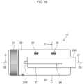
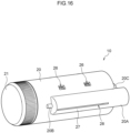
- the test strip holder 10 in which the door member 40 is made into a different form is illustrated in Fig. 15 and Fig. 16 in a front view and in a front perspective view, respectively.
- a door accommodating portion 27 that is shaped as a cylinder and projects outward is provided at the side surface of the holding member 20.
- the door accommodating portion 27 is a shape in which a portion of a solid cylinder, whose diameter is smaller than the holding member 20 and whose length in the longitudinal direction is greater than or equal to the length of the test strip 90, projects outward from the holding member 20.
- a discharge opening 28, which is an opening of the same length or longer than the test strip 90, is provided along the longitudinal direction of the door accommodating portion 27. The discharge opening 28 communicates the interior and the exterior of the door accommodating portion at the lower side of the door accommodating portion 27.
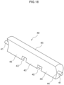
- the door member 40 which is the shape illustrated in an outer perspective view in Fig. 17 and in an inner perspective view in Fig. 18 , is accommodated in the door accommodating portion 27.
- the door member 40 has a shape that is substantially crescent-shaped in cross-section, as if a portion of the side surface of a solid cylinder has been hollowed out at the concavely curved surface of the cylindrical surface 22 of the holding member 20.
- the convexly curved surface of this side surface is called a cutting-off portion 45, and the concavely curved surface is called an inclined surface 44.
- the cut-out portions 42 that are rectangular may be formed in two places of the lower edge of the inclined surface 44.
- the front side of the door accommodating portion 27 is connected to the bearing 20B that is cylindrical and has a smaller diameter than the door accommodating portion 27 and bulges out from the side surface of the holding member 20.
- One of the door shafts 41 is accommodated in this bearing 20B.
- the sensing windows 26 that are rectangular are formed at two places in a vicinity above the door accommodating portion 27.
- the door member 40 is provided at the side surface of the holding member 20 in a direction running along the longitudinal direction of the holding member 20.
- the driving shaft accommodating portion 20A which is cylindrical and bulges outward and is connected to the door accommodating portion 27, is provided at the another end side of the holding member 20.
- the door driving shaft 46 (see Fig. 4 ) is accommodated in this driving shaft accommodating portion 20A.
- the door driving shaft 46 and the door shafts 41 have the same axial centers.
- the door driving shaft 46 is held by the opening/closing operation device 4 (see Fig. 11 ) that is similar to the first exemplary embodiment. Due to the door driving shaft 46 rotating around the axial center, the door member 40 rotates.
- the connecting portion 20C that is cylindrical and has a slightly smaller diameter projects out at the another end side of the holding member 20. This connecting portion 20C is connected to the rotation driving device 3 (see Fig.
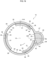
- the inclined surface 44 of the door member 40 is the inner peripheral surface that is shaped as a concave surface and is flush with the cylindrical surface 22 that is the inner side surface of the holding member 20, at the time when the door member 40 is closed as illustrated in Fig. 19 .
- the cutting-off portion 45 that is at the side opposite the inclined surface 44 is shaped as a cylindrical, convex surface that corresponds to the cylindrical, concave surface of the interior of the door accommodating portion 27.
- the cutting-off portion 45 closes both the opening portion 24 and the discharge opening 28.
- the cutting-off portion 45 cuts the interior of the holding member 20 off from the exterior.
- the test strip 90 can be removed to the outer side of the holding member 20 by opening the door member 40 by the opening/closing operation device 4 illustrated in Fig. 11 .
Landscapes
- Health & Medical Sciences (AREA)
- Chemical & Material Sciences (AREA)
- Physics & Mathematics (AREA)
- Life Sciences & Earth Sciences (AREA)
- General Health & Medical Sciences (AREA)
- Analytical Chemistry (AREA)
- General Physics & Mathematics (AREA)
- Immunology (AREA)
- Biochemistry (AREA)
- Pathology (AREA)
- Engineering & Computer Science (AREA)
- Biomedical Technology (AREA)
- Chemical Kinetics & Catalysis (AREA)
- Clinical Laboratory Science (AREA)
- Hematology (AREA)
- Plasma & Fusion (AREA)
- Optics & Photonics (AREA)
- Biophysics (AREA)
- Molecular Biology (AREA)
- Urology & Nephrology (AREA)
- Food Science & Technology (AREA)
- Medicinal Chemistry (AREA)
- Automatic Analysis And Handling Materials Therefor (AREA)
Abstract
Description
- The present invention relates to a test strip holder and a test strip discharging mechanism.
- In order to carry out measurement continuously by using test strips that are used to measure a predetermined item included in a sample of urine or the like, a mechanism is used that inserts plural test strips into a device, and takes the inserted test strips out one-by-one. A specimen is applied to the test strip that is taken out by the mechanism, and the predetermined item is measured.
- For example, in the technique disclosed in Japanese Patent Application Laid-Open (
JP-A) No. H05-264540 JP-A No. 2000-35433 - In the technique of
JP-A No. H05-264540 JP-A No. 2000-35433 - The present disclosure provides a test strip holder that can reliably take test strips out one-by-one, and at which damage that arises at the test strips accompanying this removal is reduced.
- A test strip holder of an aspect of the present disclosure has a holding member, an opening portion, a sorting member, a pushing piece, and a sorting piece. At least a portion of the lower side of the inner periphery of the holding member is a cylindrical surface. A test strip that is elongated and has thickness X is held at the interior of the holding member. The direction of the imaginary central axis of the cylindrical surface is a horizontal direction or a direction inclined with respect to the vertical direction. The opening portion is provided in the outer surface of the holding member. The sorting member rotates at the interior of the holding member around a rotation axis that coincides with the central axis. The pushing piece projects out from a distal end edge, which is parallel to the central axis, at the sorting member in the direction of rotation of the sorting member. The sorting piece projects out from the distal end of the pushing piece toward the cylindrical surface. The distance between the cylindrical surface and the position, which is closest to the cylindrical surface, at the distal end edge is less than X. Distance A between the cylindrical surface and the position, which is closest to the cylindrical surface, at the sorting piece satisfies X ≤ A < 2X.
- Because exemplary embodiments of the present disclosure are structured as described above, there is provided a test strip holder that can reliably take test strips out one-by-one, and at which damage that arises at the test strips accompanying this removal is reduced.
- Exemplary embodiments will be described in detail based on the following figures, wherein:
-
Fig. 1 illustrates a test strip holder of a first exemplary embodiment in a front view; -
Fig. 2 illustrates the test strip holder ofFig. 1 in a front perspective view; -
Fig. 3 illustrates, in a front perspective view, a state in which a cap and a door member have been removed from the test strip holder ofFig. 2 ; -
Fig. 4 illustrates the test strip holder ofFig. 1 in a rear perspective view; -
Fig. 5 illustrates, in a cross-section along line B-B' ofFig. 1 , a cylindrical surface that is the inner periphery of a holding member at the test strip holder ofFig. 1 ; -
Fig. 6A illustrates a test strip in a perspective view; -
Fig. 6B illustrates the test strip in a front view; -
Fig. 6C illustrates the test strip in a side view; -
Fig. 7 illustrates, in a front perspective view, a rotating member that is accommodated in the test strip holder ofFig. 1 ; -
Fig. 8 illustrates the rotating member ofFig. 5 in a rear perspective view; -
Fig. 9 is a cross-sectional view along line A-A' ofFig. 1 ; -
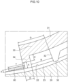
Fig. 10 illustrates a pushing piece and a sorting piece in an enlarged manner; -
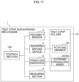
Fig. 11 is a functional block drawing of a test strip discharging mechanism; -
Fig. 12 is a block drawing illustrating hardware structures of a control section ofFig. 11 ; -
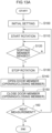
Fig. 13A is a flowchart illustrating an overview of test strip discharging processing; -
Fig. 13B is a flowchart illustrating an overview of test strip discharging processing; -
Fig. 14A illustrates a state of holding the test strip, in a cross-sectional view; -
Fig. 14B illustrates a state of holding the test strip, in a cross-sectional view; -
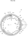
Fig. 14C illustrates a state of holding the test strip, in a cross-sectional view; -
Fig. 14D illustrates a state of holding the test strip, in a cross-sectional view; -
Fig. 14E illustrates a state in which the test strip is discharged, in a cross-sectional view; -
Fig. 15 illustrates a test strip holder of a second exemplary embodiment in a front view; -
Fig. 16 illustrates the test strip holder ofFig. 15 in a front perspective view; -
Fig. 17 is an outer perspective view of the door member; -
Fig. 18 is an inner perspective view of the door member; -
Fig. 19 is a cross-sectional view along line C-C' ofFig. 15 ; -
Fig. 20A illustrates a state in which the test strip is discharged, in a cross-sectional view; -
Fig. 20B illustrates a state in which the test strip is discharged, in a cross-sectional view; -
Fig. 20C illustrates a state in which the test strip is discharged, in a cross-sectional view; -
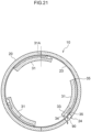
Fig. 21 illustrates a test strip holder of a third exemplary embodiment in a cross-sectional view; -
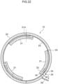
Fig. 22 illustrates a modified example of the third exemplary embodiment in a cross-sectional view; and -
Fig. 23 illustrates a portion of a test strip holder of a fourth exemplary embodiment in a cross-sectional view. - Exemplary embodiments of the present disclosure are described hereinafter with reference to the drawings. Note that reference numerals that are used in common in the respective drawings indicate the same objects even if not stated in the following descriptions of the respective drawings.
-
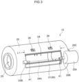
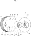
Fig. 1 illustrates atest strip holder 10 of a first exemplary embodiment in a front view.Fig. 2 illustrates thetest strip holder 10 in a front perspective view.Fig. 3 illustrates, in a front perspective view, a state in which acap 21 and adoor member 40 have been removed from thetest strip holder 10.Fig. 4 illustrates thetest strip holder 10 in a rear perspective view. Note that, in the following description, a direction in which a cap 21 (Fig. 1 ,Fig. 2 ,Fig. 4 ) is provided at thetest strip holder 10 is called a front side, and a direction in which a connectingportion 20C is provided at thetest strip holder 10 is called a rear side. - The
test strip holder 10 of the present exemplary embodiment has a holdingmember 20 whose side surface is cylindrical. As illustrated inFig. 1 ,Fig. 2 andFig. 4 , acap 21 that is shaped as a short cylinder is attached to one end side of the holdingmember 20. Adoor member 40, which is substantially rectangular as seen in a front view (Fig. 1 ), is provided at a side surface of the holdingmember 20. A pair ofbearings 40B that project out toward an outer side in a cylindrical shape are provided at both ends of thedoor member 40. The pair ofbearings 40B are respectively connected tobearings 20B that are shaped as cylinders of the same diameter and bulge out from the side surface of the holdingmember 20. A pair of door shafts 41 (Fig. 3 ) are accommodated in thesebearings door member 40 is pivotally supported at the pair ofdoor shafts 41, and can rotate as described later. - On the other hand, a driving
shaft accommodating portion 20A, which is cylindrical and bulges out toward the outer side, is provided at another end side of the holdingmember 20. As illustrated inFig. 4 , adoor driving shaft 46 is accommodated in this drivingshaft accommodating portion 20A. Thedoor driving shaft 46 and thedoor shafts 41 have the same axial centers. Thedoor driving shaft 46 is held at an opening/closing operation device 4 (seeFig. 11 ) that is described later, and thedoor member 40 is opened and closed due to thedoor driving shaft 46 rotating around the axial center. Moreover, the connectingportion 20C that is shaped as a cylinder of a slightly smaller diameter projects out at the another end side of the holdingmember 20. This connectingportion 20C is connected to a rotation driving device 3 (seeFig. 11 ) when thetest strip holder 10 is attached to a teststrip discharging mechanism 1 that is described later. Arotation driving shaft 36 of a rotating member 30 (Fig. 7 ,Fig. 8 ) that is described later is visible from an opening provided at the center of the connectingportion 20C. - As illustrated in
Fig. 5 that shows the cross-section along line B-B' ofFig. 1 , at least a portion of (in the present exemplary embodiment, all of) the lower side of the inner periphery of the holdingmember 20 is acylindrical surface 22 that has a cylindrical shape. The central axis of thecylindrical surface 22 is an imaginary central axis 15 (Fig. 1 ) of the holdingmember 20. Moreover, plural innerperipheral grooves 23 are formed in thecylindrical surface 22 along the peripheral direction. Note that, at the holdingmember 20, there are cases in which the upper half may be an openingportion 24, provided that at least a portion of the lower side (e.g., half) is thecylindrical surface 22. - A
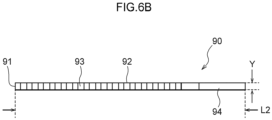
test strip 90 that is elongated and illustrated inFig. 6A to Fig. 6C is held at the interior of the holdingmember 20 of thetest strip holder 10. In the present exemplary embodiment, a urine test strip for measuring a concentration of or the absence or presence of a physical characteristic or a specific component within urine, is given as an example of thetest strip 90. - As illustrated, the
test strip 90 is a structure in whichplural reagent pads 93 are disposed on a strip-shapedsubstrate 94. A graspingportion 95 that is grasped within an unillustrated measuring device is provided at one end of thesubstrate 94, and the other region of thesubstrate 94 is a reagent pad placement region 96 (seeFig. 6C ). Theplural reagent pads 93 are disposed at the reagentpad placement region 96 in series along the longitudinal direction with a fixed interval therebetween. - The material of the
substrate 94 is not particularly limited, and examples thereof are resin, metal, glass and the like. The color of the substrate is not particularly limited, and may be any of white, grey, black, a chromatic color, or transparent. The size of thesubstrate 94 is not particularly limited, and is determined appropriately in accordance with items to be tested, standards of an analyzing device that is used, and the like, and can be, for example, a length of 50 ~ 150 mm, a width of 2 ~ 10 mm, and a thickness of 0.1 ~ 1.0 mm. In the present exemplary embodiment, the length in a long-length direction of thetest strip 90, i.e., the length oflong side 92, is L2 (Fig. 6B ), and the length in a short-length direction, i.e., the length ofshort side 91, is Y (Fig. 6B ). Accordingly, the length of the holdingmember 20 in the longitudinal direction is greater than or equal to the length of the test strip. In this way, the size of thetest strip 90 that is suitable for thetest strip holder 10 of the present exemplary embodiment is limited. - Examples of the material of the
reagent pad 93 are filter paper, glass-fiber filter paper, knit fabric, woven fabric, non-woven fabric, a membrane filter, a porous resin sheet, a plastic film, and the like. Further, the shape of thereagent pad 93 is not particularly limited, and is square, rectangular, circular, oval or the like. The size of thereagent pad 93 is not particularly limited, and, when the shape thereof is rectangular, for example, the size can be made to be a length and width of 2 ~ 10 mm and a thickness of 0.05 ~ 1.0 mm. In the present exemplary embodiment, the thickness of the thick-walled portion is X (Fig. 6C ). At the time of forming thereagent pad 93, the reagent pad may be molded into a predetermined shape after the reagent is suffused into the above-described pad material, or the reagent may be suffused after the pad material is molded into a predetermined shape. The suffusing of the reagent can be carried out by, for example, immersing the pad material in a reagent solution and drying the pad material. Further, for example, an adhesive or a tackifier can be used in disposing thereagent pads 93 at thesubstrate 94. For example, polyurethane, acrylic, vinyl chloride, epoxy, nylon, hot melt, cyanoacrylate, rubber or the like can be used as the adhesives and tackifiers. - Note that the thickness X of the
test strip 90 is a distance of the thickest portion of the test strip used in thetest strip holder 10, and, at the above-describedtest strip 90, is the thickness of thereagent pad 93. If thetest strip 90 has a portion that is thicker than thereagent pad 93, the thickness of that place is X. - At the test
strip discharging mechanism 1 that is described later, thetest strip holder 10 is attached such that the direction of the imaginary central axis 15 (Fig. 1 ) of the holdingmember 20 is the horizontal direction. However, the direction of thiscentral axis 15 is not limited to the horizontal direction, and thetest strip 90 may be held provided that the direction is a direction that is inclined with respect to the vertical direction (in other words, is not the vertical direction). Namely, of the angles formed by the direction of thecentral axis 15 and the vertical direction, the magnitude of the angles that are less than or equal to 90° is greater than 0° and less than or equal to 90°, and preferably greater than or equal to 30° and less than or equal to 90°, and more preferably greater than or equal to 45° and less than or equal to 90°, and even more preferably greater than or equal to 60° and less than or equal to 90°, and most preferably 90°, i.e., the horizontal direction. - Cut-out
portions 42 that are rectangular are formed in two places of one of the long sides of thedoor member 40. This long side is divided into three scoopingportions 43 that are shaped as tongue pieces by these cut-outportions 42 that are at two places. Further, sensingwindows 26 that are rectangular are formed in the side surface of the holdingmember 20 at two places that are in the vicinity of the other long side of thedoor member 40. - As illustrated in
Fig. 3 that shows a state in which thecap 21 and thedoor member 40 have been removed from thetest strip holder 10, the openingportion 24 that is rectangular is provided in the side surface of the holdingmember 20 along the longitudinal direction. Thedoor member 40 is provided at the openingportion 24 so as to be able to open and close. A sortingmember 31 of the rotatingmember 30, which is accommodated in the interior of the holdingmember 20 and rotates within the holdingmember 20 with thecentral axis 15 being therotation axis 15, can be seen from the openingportion 24. Length L1 of the openingportion 24 in the longitudinal direction is a length that is greater than or equal to the length L2 of thetest strip 90 in the longitudinal direction, or, in other words, is a length of an extent that does not present problems with thetest strip 90 being discharged from the openingportion 24. Further, aninsertion opening 25 for inserting thetest strip 90 into the holdingmember 20 is formed in the center of the front side of the holdingmember 20. Note that the openingportion 24 is provided in the cylindrical side surface of the holdingmember 20. For example, in a case in which thetest strip holder 10 is placed horizontally, the openingportion 24 may be provided in the lower side portion of the side surface of the holdingmember 20. Note that it suffices for the openingportion 24 to be provided at an "outer surface" in a sense of including both the "side surface" and the "bottom surface", and not only at the "side surface", in the geometrical sense, of the holding member that is cylindrical. - Note that
central line 24A that is shown by a dashed line in the drawings is an imaginary line that bisects the openingportion 24 along the longitudinal direction. Here, thecentral line 24A is at a position that is at the lower side in the rotation direction, with respect to anuppermost position 31A (Fig. 9 ) that the sortingmember 31 at the interior of the holdingmember 20 reaches. Assuming that the rotational angle of thisuppermost position 31A is 0°, thecentral line 24A is preferably at a position of a rotational angle of greater than or equal to 45° and less than or equal to 90°, and more preferably is at the position of 90°. - The rotating
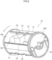
member 30 that is accommodated in the holdingmember 20 at thetest strip holder 10 is illustrated in the front perspective view ofFig. 7 and the rear perspective view ofFig. 8 . The rotatingmember 30 has afront plate 30A that is circular and positioned at the front side, and arear plate 30B that is circular and is the same diameter as thefront plate 30A and is positioned at the rear side so as to be apart from thefront plate 30A by a distance that is longer than the length L2 of the long side of the test strip. Moreover, the rotatingmember 30 has a structure in which plural, and specifically, three, of the sortingmembers 31 are disposed between thefront plate 30A and therear plate 30B. The sortingmembers 31 are respectively provided so as to be apart by a distance that is longer than the length Y of theshort side 91 of the test strip. The diameters of thefront plate 30A and therear plate 30B are the same as the diameter of the cylinder formed by thecylindrical surface 22 of the holdingmember 20. Thefront plate 30A and therear plate 30B are fixed by the sortingmembers 31 such that the central axis of the circle of thefront plate 30A and the central axis of the circle of therear plate 30B coincide. - In other words, the central axis of the
front plate 30A and the central axis of therear plate 30B coincide, and this is therotation axis 15 of the rotatingmember 30. Therotation driving shaft 36 projects out toward the rear side along the central axis of therear plate 30B from the center of the circle of therear plate 30B (Fig. 8 ). When the rotatingmember 30 is accommodated such that the outer peripheral surface of thefront plate 30A and the outer peripheral surface of therear plate 30B of the rotatingmember 30 contact thecylindrical surface 22 of the holdingmember 20, thecentral axis 15 of the holdingmember 20 and thecentral axis 15 of the rotatingmember 30 coincide because the diameter of the cylinder formed by thecylindrical surface 22, and the diameter of thefront plate 30A and the diameter of therear plate 30B, are the same. - The
rotation driving shaft 36 is connected to therotation driving device 3 that is described later. Due to rotational force from therotation driving device 3 being transmitted, the entire rotatingmember 30 rotates in the direction of the arrows shown inFig. 7 andFig. 8 . Thereby, the sortingmembers 31 rotate within the holdingmember 20 around therotation axis 15 that coincides with thecentral axis 15, and thereby, thetest strips 90 are moved at the interior of the holdingmember 20. Namely, the sortingmembers 31 are formed as bodies separate from the holdingmember 20, and rotate with respect to the holdingmember 20. In other words, the sortingmembers 31 rotate around thecentral axis 15 of the holdingmember 20 while maintaining a predetermined distance from thecentral axis 15. - A circular opening is provided in the
front plate 30A at the center of the circle of thefront plate 30A (Fig. 8 ), and a cylinder of the same outer diameter as this opening is fit therein (Fig. 7 ). The cylinder projects out forward from thefront plate 30A. When the rotatingmember 30 is accommodated in the holdingmember 20, the cylinder is connected to theinsertion opening 25 of the holdingmember 20. Accordingly, thetest strip 90 that is inserted in theinsertion opening 25 of thetest strip holder 10 is held between thefront plate 30A and therear plate 30B. - The sorting
members 31 are members that are substantially plate-shaped and are provided along the direction of therotation axis 15. The sortingmembers 31 are mounted between the circular surface at the inner side of thefront plate 30A and the circular surface at the inner side ofrear plate 30B, so as to be apart from therotation axis 15. The sortingmember 31 has an outer peripheral surface that faces in the direction of the outer side of the rotatingmember 30, an inner peripheral surface that faces in the direction of therotation axis 15, a first side surface that is parallel to thecentral axis 15 and faces in the rotating direction, and a second side surface that is parallel to thecentral axis 15 and faces in the direction of the side opposite the rotating direction. The inner peripheral surface and the outer peripheral surface are curved surfaces whose centers are therotation axis 15. The first side surface and the second side surface are surfaces connecting the outer peripheral surface and the inner peripheral surface, and are flat surfaces that expand from the outer peripheral surface in the direction toward the central axis. Plural slidingprojections 35 are disposed at the outer peripheral surface, along the edge between the outer peripheral surface and the first side surface. The slidingprojections 35 are projections that fit into the innerperipheral grooves 23 provided at thecylindrical surface 22, at the time when the rotatingmember 30 is accommodated in the holdingmember 20. The slidingprojections 35 are shaped as truncated cones whose bottom surfaces are square and that become pointed toward the outer side of the rotatingmember 30. The surfaces at the rotating direction sides of the slidingprojections 35 are flat surfaces that expand toward therotation axis 15, and form portions of the first side surface of the sortingmember 31. The first side surface, which includes the rotating direction side surfaces of the slidingprojections 35, is adistal end edge 32 of the sortingmember 31. - Each of the sorting
members 31 has adistal end edge 32 that corresponds to the distal end portion in the rotating direction and is parallel to the central axis. Two pushingpieces 33, which are rectangular parallelepiped and have predetermined lengths in the longitudinal direction, project out in parallel in the rotating direction from thedistal end edge 32 by a predetermined distance D (seeFig. 10 ) that is longer than at least distance B. The number of the pushingpieces 33 is not limited to two. It suffices for the pushingpieces 33 to be able to hold thetest strip 90 even during rotation, and the number thereof may be one or may be three or more. Further, the positions of the pushingpieces 33 in the longitudinal direction are not particularly limited, provided that they can hold thetest strip 90 even during rotation. Moreover, a sortingpiece 34 that is rectangular parallelepiped projects out from the distal end of the pushingpiece 33 toward the outer side, i.e., toward the cylindrical surface 22 (Fig. 5 ). Theplural sliding projections 35 are disposed at the outer peripheral surface of the sortingmember 31 in rows along thedistal end edge 32 and arear end edge 32A respectively, toward the cylindrical surface 22 (Fig. 5 ). The slidingprojections 35 provided at the outer peripheral surface of the sortingmember 31, and the inner peripheral grooves 23 (Fig. 5 ) provided at thecylindrical surface 22 of the holdingmember 20, are formed as a structure of projections and indentations that mesh with each other. The pushingpieces 33 and the sortingpieces 34 are both fixed to the sortingmember 31 that rotates around thecentral axis 15 of the holdingmember 20 while maintaining a predetermined distance from thecentral axis 15. Therefore, the pushingpieces 33 and the sortingpieces 34 also rotate around thecentral axis 15 while maintaining a predetermined distance from thecentral axis 15. -
Fig. 9 is a cross-sectional view along line A-A' ofFig. 1 . Thecylindrical surface 22 of the holdingmember 20 has a cross-section that is a substantially circular cross-section, and the inner peripheral surface of thedoor member 40 provided at the openingportion 24 is a circular arc shape that is flush with thecylindrical surface 22 of the holdingmember 20. Further, the three sortingmembers 31 have cross-sectional shapes that are approximately circular arc shaped, and are disposed uniformly with respect to thecentral axis 15. Note that the sortingmembers 31 do not absolutely have to be disposed uniformly, and the number thereof is not limited to three. However, the number of thetest strips 90 that can be held in one round of the rotatingmember 30 increases in accordance with the number of the sortingmembers 31, and it is preferable thatplural sorting members 31 be provided in order to improve the speed of taking out thetest strips 90 from thetest strip holder 10. On the other hand, the greater the number of sortingmembers 31, the narrower the interval between the front andrear sorting members 31, and the higher the probability of rotation without being able to hold the test strips 90. Therefore, the number of sortingmembers 31 is preferably three to five. Moreover, the slidingprojections 35 that are provided at both the distal end side and the rear end side of the sortingmember 31 fit in the innerperipheral grooves 23 of thecylindrical surface 22, and slide along the innerperipheral grooves 23 in the rotating direction that is shown by the arrows in the drawings. Note that, provided that two or more of the slidingprojections 35 are provided, thetest strip 90 becoming bitten-in between the sortingmember 31 and thecylindrical surface 22 can be inhibited even if the slidingprojections 35 and the innerperipheral grooves 23 are not meshing together as indentations and projections. - The positional relationships between the
cylindrical surface 22, and the pushingpiece 33 and thesorting piece 34 of the sortingmember 31 are shown in the enlarged sectional view ofFig. 10 . Namely, the distance between thecylindrical surface 22 and the position nearest to thecylindrical surface 22 at thedistal end edge 32 of the sorting member 31 (i.e., the distal end of the sliding projection 35) is set to be less than the thickness X of the test strip 90 (Fig. 6C ). Thereby, thetest strip 90 becoming bitten-in between the sortingmember 31 and thecylindrical surface 22 is inhibited, and thedistal end edge 32 can push thetest strip 90 in the rotating direction as the sortingmember 31 rotates. Further, distance A between thecylindrical surface 22 and the position of the sortingpiece 34 that is nearest to thecylindrical surface 22 is set to be greater than or equal to the thickness X of thetest strip 90 and less than two times X. - Namely, the distance A is a distance such that one of the
test strips 90 can enter in between the sortingpiece 34 and thecylindrical surface 22, but two or more of the test strips cannot enter in. Thereby, two or more of thetest strips 90 overlapping and simultaneously entering in between the pushingpiece 33 and thecylindrical surface 22 is inhibited. Note that, from the standpoints of tolerating errors in manufacturing of thetest strips 90 and ease of entry of thetest strips 90, the distance A is preferably greater than or equal to 1.1 times the thickness X of thetest strip 90, and more preferably greater than or equal to 1.2 times. Further, because thereagent pad 93 at thetest strip 90 such as that described above is formed of a material such as filter paper or the like, there are cases in which, due to thereagent pad 93 being pressed, the thickness X becomes thinner than X. Accordingly, the distance A is preferably less than 1.8 times the thickness X of thetest strip 90, and more preferably less than 1.6 times. - Further, the distance B from the
distal end edge 32 of the sorting member 31to thesorting piece 34, with respect to the length Y (Fig. 6B ) in the short-length direction of thetest strip 90, is set to be greater than or equal to Y and less than two times Y. Namely, the distance B is a distance that is such that one of thetest strips 90 can enter-in in the rotating direction between thecylindrical surface 22 and the pushingpieces 33 that are disposed between thedistal end edge 32 and the sortingpieces 34, but two or more of thetest strips 90 cannot enter-in. Thereby, two or more of thetest strips 90 being held so as to be lined-up in the rotating direction between the pushingpieces 33 and thecylindrical surface 22 is inhibited. Note that, from the standpoints of tolerating errors in manufacturing of thetest strips 90 and ease of entry of thetest strips 90, the distance B is preferably greater than or equal to 1.1 times the length Y of thetest strip 90, and more preferably greater than or equal to 1.2 times. Further, there is a concern that two or more of the test strips will enter-in if thetest strips 90 stand-up. Therefore, the distance B is preferably less than 1.8 times the length Y of thetest strip 90, and more preferably less than 1.6 times. - Moreover, length C of the portion which projects out from the pushing
piece 33 toward thecylindrical surface 22 at the sortingpiece 34 is set to be greater than or equal to 0.5 times the thickness X of thetest strip 90, and less than 1.5 times X. Namely, the length C is a distance that is such that the onetest strip 90 that is between thecylindrical surface 22 and the pushingpieces 33 disposed between thedistal end edge 32 and the sortingpieces 34 can be held, but two or more of thetest strips 90 cannot be held. Due to these conditions of the distance B and the length C, even if the sorting member 31 (the pushing pieces 33) rotates while holding two or more of thetest strips 90, immediately after the pushingpieces 33 reach theuppermost position 31A (i.e., when the pushingpieces 33 reach the position at which the vertically-downward vector is small), only thetest strip 90 that is at the pushingpieces 33 side from the sortingmember 31 is held at the inner sides of the projecting portions of length C of the sortingpieces 34, and thetest strips 90 other than that cannot be held by the sortingpieces 34, and therefore, fall down. Note that length C being greater than or equal to 0.5 times the thickness X of thetest strip 90 and less than 1.0 times X is more preferable from the standpoint that the test strips that are other than the onetest strip 90 that is held do not at all contact the inner sides of the projecting portions of length C of the sortingpieces 34, and therefore, can reliably be made to drop down. - Further, distance E (see
Fig. 10 ), which is the length of the sortingpiece 34 in the rotating direction, with respect to the length Y of thetest strip 90 in the short-length direction, is set to be less than Y, and preferably is less than 0.5 times the length Y of thetest strip 90. Due to this condition of the distance E, the test strip that is held between the sortingpieces 34 and thecylindrical surface 22 can fall down immediately after theuppermost position 31A is reached. Note that the distance E is substantially the same length as the distance obtained by subtracting the distance B from the distance D. - A functional block drawing of the test
strip discharging mechanism 1 is illustrated inFig. 11 . The teststrip discharging mechanism 1 is structured as a measuring apparatus that measures, by thetest strip 90 to which a specific reagent has been applied, the concentration of or the absence or presence of a physical characteristic or a specific component of a biological specimen such as, for example, a urine sample. - A
control section 100 controls the respective sections of the teststrip discharging mechanism 1. Thecontrol section 100 controls aproximity sensor 2, therotation driving device 3, the opening/closing operation device 4, and ameasuring section 5 by hardware structures described later. When thetest strip holder 10 is attached to the teststrip discharging mechanism 1, as described above, therotation driving device 3 is connected to the rotation driving shaft 36 (Fig. 8 ) of the rotatingmember 30, and further, the opening/closing operation device 4 is connected to the door driving shaft 46 (Fig. 4 ) of thedoor member 40. Theproximity sensor 2 is structured by, for example, an optical sensor or a proximity sensor or the like, and, through the sensing windows 26 (Fig. 9 ) of the holdingmember 20, senses the approach of the sortingmember 31 to the openingportion 24. Note that theproximity sensor 2 may sense the approach of thetest strip 90 that is held at the sortingmember 31. In accordance with the sensing by theproximity sensor 2, thecontrol section 100 drives therotation driving device 3, and rotates or stops the rotating member 30 (the sorting members 31). Further, in accordance with the sensing by theproximity sensor 2, thecontrol section 100 drives the opening/closing operation device 4, and opens or closes thedoor member 40. Note that, in a case in which an opening/closing member 50 (seeFig. 22 ) which is not thedoor member 40 is provided at the openingportion 24, the opening/closing operation device 4 opens and closes the opening/closingmember 50 instead of thedoor member 40. Further, thecontrol section 100 also controls the measuringsection 5 that serves as a measuring apparatus and is structured by various portions and devices. - As illustrated by the hardware structures in
Fig. 12 , thecontrol section 100 has a CPU (Central Processing Unit) 101, a ROM (Read Only Memory) 102, a RAM (Random Access Memory) 103, and astorage 104. These respective structures are connected so as to be able to communicate with one another viabus 109. - The
CPU 101 is a central computing processing unit, and executes various programs and controls respective sections. Namely, theCPU 101 reads-out a program from theROM 102 or thestorage 104, and executes the program by using theRAM 103 as a workspace. TheCPU 101 carries out control of the above-described respective structures, and various computing processings, in accordance with programs recorded in theROM 102 or thestorage 104. - The
ROM 102 stores various programs and various data. TheRAM 103 temporarily stores programs and data as a workspace. Thestorage 104 is structured by an HDD (Hard Disk Drive), an SSD (Solid State Drive) or a flash memory, and stores various programs, including the operating system, and various data. In the present aspect, programs and various data relating to measurements and judgments are stored in theROM 102 or thestorage 104. Further, measured data also can be stored in thestorage 104. - The
control section 100 executes control of theproximity sensor 2, therotation driving device 3, the opening/closing operation device 4 and themeasuring section 5 due to, among the above-described hardware structures, theCPU 101 executing the above-described programs. - Due to the above-described structure, by control of the
control section 100, therotation driving device 3 can stop the rotation of the sortingmember 31 when the sortingmember 31 approaches the openingportion 24, and can restart rotation of the sortingmember 31 when the opening/closing operation device 4 closes the openingportion 24. Thecontrol section 100 can also carry out control such that this operation of the opening/closing operation device 4 is carried out due to theproximity sensor 2 sensing the approach of the sortingmember 31. Moreover, thecontrol section 100 can control the stopping of rotation by therotation driving device 3 due to theproximity sensor 2 sensing the approach of the sortingmember 31, and can control the restarting of rotation by therotation driving device 3 when the opening/closing operation device 4 closes the openingportion 24. - The taking-out of the
test strip 90 by thetest strip holder 10 of the present exemplary embodiment is described next with reference to the flowchart ofFig. 13A (orFig. 13B ) and the cross-sectional views ofFig. 14A to Fig. 14E . Note that the cross-sectional views ofFig. 14A to Fig. 14E explain operation focusing on one of the sortingmembers 31, but, of course, operations at the other two sortingmembers 31 also are executed concurrently. - First, when the power of the test
strip discharging mechanism 1 is turned on, initial setting of the devices is executed in the step shown in S100. This initial setting also includes setting the rotatingmember 30 at its initial position of rotation due to thecontrol section 100 controlling therotation driving device 3. - Then, after preparations for measurement have been completed, in the step shown in S110, the
control section 100 drives therotation driving device 3 and starts rotation of the rotatingmember 30. In the step shown in S120, thecontrol section 100 continues the rotation of the rotatingmember 30 until theproximity sensor 2 senses the sortingmember 31 through thesensing windows 26. Note that, in the case of a structure that does not have theproximity sensor 2 and that employs, for example, a step motor as therotation driving device 3, in the step shown in S120' in the flowchart ofFig. 13B , thecontrol section 100 can continue the rotation of the rotatingmember 30 until a predetermined number of steps have passed (e.g., the number of steps needed until the next sortingmember 31 approaches the openingportion 24 after stoppage of rotation and restarting of rotation). - During this time, in
Fig. 14A , theplural test strips 90 stay at the lower portion of the interior space of the holdingmember 20. The pushingpieces 33 of the sortingmember 31 push, in the rotating direction, theseplural test strips 90 that are staying there. - When the sorting
member 31 continues to rotate and comes to a position past the lowermost position in the vertical direction as illustrated inFig. 14B , only one of thetest strips 90 that were positioned at the outermost side slips through the gap of width A (seeFig. 10 ) that is between the sortingpieces 34 and thecylindrical surface 22, and enters in to a position at which thelong side 92 thereof is made to contact thedistal end edge 32. Note that there are cases in which only a portion of anothertest strip 90 as well enters into the gap between the sortingpieces 34 and thecylindrical surface 22. Theother test strips 90 are raised up by the pushingpieces 33. - When the sorting
member 31 continues to rotate further, and the pushingpieces 33 reach theuppermost position 31A as illustrated inFig. 14C , all of thetest strips 90 that could not enter into the gap between the sortingpieces 34 and thecylindrical surface 22 fall downward. Then, when the sortingmember 31 rotates further to the position shown inFig. 14D , thetest strip 90, at which only a portion thereof entered into the gap between the sortingpieces 34 and thecylindrical surface 22, also falls down ultimately, but thetest strip 90, which entered in up to the point of contacting thedistal end edge 32, is held by the pushingpieces 33 and the sortingpieces 34 and avoids falling down. - Namely, due to the distance A between the
cylindrical surface 22 and the nearest position of the sortingpiece 34 to thecylindrical surface 22 satisfying X ≤ A < 2X, only one of thetest strips 90 is held at a position that is rotated slightly from theuppermost position 31A due to the sortingmember 31 rotating. Note that, due to the distance B from thedistal end edge 32 of the pushingpiece 33 to thesorting piece 34 satisfying Y ≤ B < 2Y, and the length C of the portion of the sortingpiece 34 that projects out from the pushingpiece 33 toward thecylindrical surface 22 satisfying 0.5X ≤ C < 1.5X, the sortingmember 31 can be set in a state of even more reliably holding only thetest strip 90 at a position that is rotated slightly from theuppermost position 31A. - Further, when the sorting
member 31 rotates to the position illustrated inFig. 14E , in the step shown in S120, theproximity sensor 2 senses the approach of the sorting member 31 (or, in the step shown in S120', thecontrol section 100 senses the passage of the predetermined number of steps), and, in the step shown in S130, thecontrol section 100 stops driving of therotation driving device 3, and rotation of the sortingmember 31 stops. Then, in the next step shown in S140, thecontrol section 100 drives the opening/closing operation device 4, and rotates and opens thedoor member 40 to the state illustrated inFig. 14E . - Due to this rotation of the
door member 40, simultaneously with the cut-outportions 42 reaching the positions of the pushingpieces 33, the scoopingportions 43 collide with the pushingpieces 33 or thetest strip 90. Due to this collision, impact is applied to thetest strip 90 that was held by the pushingpieces 33 and the sortingpieces 34, and thetest strip 90 falls down from the sortingmember 31 toward the openeddoor member 40. Thetest strip 90 slides down the concavely curved surface of thedoor member 40, is discharged to the outer side from the holdingmember 20, and thereafter, thetest strip 90 is moved by unillustrated conveying means to themeasuring section 5, and is provided to the predetermined measurement thereat. - Then, in the step shown in S150, the
control section 100 again drives the opening/closing operation device 4, rotates thedoor member 40 reversely, and again closes thedoor member 40 as in the state illustrated inFig. 14A . For the timing of closing thedoor member 40, a discharge sensor that senses that thetest strip 90 has been discharged to the outer side from the holdingmember 20 may be provided, and thedoor member 40 may be closed due to the discharging of thetest strip 90 being sensed by the discharge sensor. Otherwise, thedoor member 40 may be closed after a predetermined time has elapsed from the opening thereof. Then, in the step shown in S160, thecontrol section 100 judges whether or not there is a next measurement. If there is a next measurement, thecontrol section 100 again returns to the step shown in S110, and drives therotation driving device 3, and restarts the rotation of the rotatingmember 30. - In this way, because the
door member 40 is opened only during the discharging of thetest strip 90 from the holdingmember 20, even if the flow line for the time of opening and closing thedoor member 40 is on the flow line by which the sortingmember 31 rotates, the movement of the sortingmember 31 is not affected. In addition, in a case of using the holdingmember 20 that is airtight except for thedoor member 40, thetest strips 90 that are accommodated in the holdingmember 20 can be cut-off from outside air except at the time when thedoor member 40 is opened. Thereby, changes in the quality of thetest strips 90 due to humidity of the outside air or the like can be prevented. - The
test strip holder 10 in which thedoor member 40 is made into a different form is illustrated inFig. 15 andFig. 16 in a front view and in a front perspective view, respectively. Adoor accommodating portion 27 that is shaped as a cylinder and projects outward is provided at the side surface of the holdingmember 20. Thedoor accommodating portion 27 is a shape in which a portion of a solid cylinder, whose diameter is smaller than the holdingmember 20 and whose length in the longitudinal direction is greater than or equal to the length of thetest strip 90, projects outward from the holdingmember 20. Further, adischarge opening 28, which is an opening of the same length or longer than thetest strip 90, is provided along the longitudinal direction of thedoor accommodating portion 27. Thedischarge opening 28 communicates the interior and the exterior of the door accommodating portion at the lower side of thedoor accommodating portion 27. - The
door member 40, which is the shape illustrated in an outer perspective view inFig. 17 and in an inner perspective view inFig. 18 , is accommodated in thedoor accommodating portion 27. Thedoor member 40 has a shape that is substantially crescent-shaped in cross-section, as if a portion of the side surface of a solid cylinder has been hollowed out at the concavely curved surface of thecylindrical surface 22 of the holdingmember 20. The convexly curved surface of this side surface is called a cutting-off portion 45, and the concavely curved surface is called aninclined surface 44. The cut-outportions 42 that are rectangular may be formed in two places of the lower edge of theinclined surface 44. This lower edge is divided, by these cut-outportions 42 that are at two places, into the three scoopingportions 43 that are shaped as tongue pieces. Thedoor shafts 41, which are provided on an axial center of the solid cylinder of thedoor member 40, project out from the both ends of thedoor member 40. - The front side of the
door accommodating portion 27 is connected to thebearing 20B that is cylindrical and has a smaller diameter than thedoor accommodating portion 27 and bulges out from the side surface of the holdingmember 20. One of thedoor shafts 41 is accommodated in this bearing 20B. Further, thesensing windows 26 that are rectangular are formed at two places in a vicinity above thedoor accommodating portion 27. Thedoor member 40 is provided at the side surface of the holdingmember 20 in a direction running along the longitudinal direction of the holdingmember 20. - On the other hand, the driving
shaft accommodating portion 20A, which is cylindrical and bulges outward and is connected to thedoor accommodating portion 27, is provided at the another end side of the holdingmember 20. The door driving shaft 46 (seeFig. 4 ) is accommodated in this drivingshaft accommodating portion 20A. Thedoor driving shaft 46 and thedoor shafts 41 have the same axial centers. Thedoor driving shaft 46 is held by the opening/closing operation device 4 (seeFig. 11 ) that is similar to the first exemplary embodiment. Due to thedoor driving shaft 46 rotating around the axial center, thedoor member 40 rotates. Moreover, the connectingportion 20C that is cylindrical and has a slightly smaller diameter projects out at the another end side of the holdingmember 20. This connectingportion 20C is connected to the rotation driving device 3 (seeFig. 11 ) when thetest strip holder 10 is attached to the teststrip discharging mechanism 1 that is similar to the first exemplary embodiment. Therotation driving shaft 36 of the rotating member 30 (Fig. 7 ,Fig. 8 ) that is similar to the first exemplary embodiment can be seen from an opening provided in the center of the connectingportion 20C. - The sorting
members 31 rotate and move thetest strips 90, which are accommodated in the holdingmember 20, along thecylindrical surface 22 that is the inner peripheral surface of the holdingmember 20. Thedoor member 40 is provided at the side surface of the holdingmember 20 so as to be able to open and close, in order to discharge thetest strip 90 to the exterior of the holdingmember 20. When closed, thedoor member 40 cuts-off the interior and the exterior of the holdingmember 20 from one another. Thedoor accommodating portion 27 covers thedoor member 40 from the outer side of the holdingmember 20. Thedoor member 40 can open and close by rotating at the interior of thedoor accommodating portion 27. - The
discharge opening 28 is provided in order to discharge, to the exterior of thedoor accommodating portion 27, the test strip that has been discharged to the exterior of the holdingmember 20, i.e., into thedoor accommodating portion 27. Thedischarge opening 28 can be opened and closed with respect to the exterior by thedoor member 40 that rotates within thedoor accommodating portion 27. Namely, when thedischarge opening 28 is closed, the interior and the exterior of thedoor accommodating portion 27 are cut-off from each other. On the other hand, when thedischarge opening 28 is open, thedoor member 40 closes the openingportion 24 of the holdingmember 20 as will be described later. - The
inclined surface 44 of thedoor member 40 is the inner peripheral surface that is shaped as a concave surface and is flush with thecylindrical surface 22 that is the inner side surface of the holdingmember 20, at the time when thedoor member 40 is closed as illustrated inFig. 19 . The cutting-off portion 45 that is at the side opposite theinclined surface 44 is shaped as a cylindrical, convex surface that corresponds to the cylindrical, concave surface of the interior of thedoor accommodating portion 27. At the time when thedoor member 40 is closed as illustrated inFig. 19 , the cutting-off portion 45 closes both the openingportion 24 and thedischarge opening 28. On the other hand, at the time when thedischarge opening 28 is open as illustrated inFig. 20C , the cutting-off portion 45 cuts the interior of the holdingmember 20 off from the exterior. - Namely, simultaneously with the cut-out
portions 42 arriving at the positions of the pushingpieces 33 due to rotation of thedoor member 40, theinclined surface 44 at the scoopingportions 43 applies impact to thetest strip 90 that was held by the pushingpieces 33 and the sortingpieces 34, and causes thetest strip 90 to be discharged out to the outer side from the holding member 20 (seeFig. 20A ). At this time, thetest strip 90 that has been discharged out and fallen down is led to the exterior of the holdingmember 20 by theinclined surface 44 of thedoor member 40. In this state, thedoor member 40 closes thedischarge opening 28 while opening the holdingmember 20. - When the
door member 40 rotates further and reaches the state illustrated inFig. 20B , thedoor member 40 again closes the openingportion 24 and thedischarge opening 28 by the cutting-off portion 45. Then, thetest strip 90 that has been discharged drops down along the inclined surface 44 (Fig. 20B ). - When the
door member 40 rotates even further and reaches the state illustrated inFig. 20C , the cutting-off portion 45 opens thedischarge opening 28 while closing the opening portion 24 (seeFig. 20C ). Thetest strip 90 that has been discharged is led along theinclined surface 44 to the openeddischarge opening 28, and thetest strip 90, which has been discharged from thedischarge opening 28 to the exterior of thedoor accommodating portion 27, moves toward the measuringsection 5, and is provided to the predetermined measurement thereat. - In the above-described second exemplary embodiment, the
door member 40 always closes at least one of the openingportion 24 of the holdingmember 20 and the discharge opening 28 of thedoor accommodating portion 27. In other words, because the openingportion 24 and thedischarge opening 28 are not open at the same time, thetest strips 90 accommodated in the holdingmember 20 can always be cut-off from outside air. Thereby, changes in the quality of thetest strips 90 due to humidity of the outside air or the like can be prevented. -
Fig. 21 illustrates thetest strip holder 10 of a third exemplary embodiment in a cross-sectional view. In the present exemplary embodiment, the openingportion 24 is at a position of being rotated approximately 135° as seen from theuppermost position 31A, and thedoor member 40 does not exist. Even with such a form, thetest strip 90, which is held by the sortingmember 31 that has rotated and has been lowered, can be made to drop down from the openingportion 24. - Note that the opening/closing
member 50 that opens and closes the openingportion 24 may be provided, as in the modified example of the present exemplary embodiment that is illustrated inFig. 22 . This opening/closingmember 50 can be opened and closed by the opening/closing operation device 4 in the block drawing ofFig. 11 . -
Fig. 23 is a cross-sectional view illustrating a portion of thetest strip holder 10 of a fourth exemplary embodiment. In the above-described first to third exemplary embodiments, the holdingmember 20 does not rotate, and the sortingmembers 31 rotate with respect to the holdingmember 20. However, in the present exemplary embodiment, the holdingmember 20, whose entire inner periphery is a cylindrical surface, itself rotates. Further, the sortingmembers 31 project out toward the inner side from the inner surface of the holdingmember 20. In other words, the sortingmembers 31 are fixed to the holdingmember 20 and rotate together with the holdingmember 20. - The opening
portion 24 is formed at a distal end side along a rotating direction with respect to the sortingmember 31 or at a side facing the pushingpiece 33 in the inner surface of the holdingmember 20, and thedoor member 40 that can open and close is provided at thisopening portion 24. In this exemplary embodiment as well, the holding of thetest strip 90 by the sortingmember 31 can be carried out in the same way as illustrated inFig. 14A to Fig. 14E . Further, assuming that the rotational angle of theuppermost position 31A is 0°, after theopening portion 24 rotates to the position of a rotational angle of greater than or equal to 90° and less than or equal to 180°, and more preferably the position of 135°, thetest strip 90 can be removed to the outer side of the holdingmember 20 by opening thedoor member 40 by the opening/closing operation device 4 illustrated inFig. 11 . - Note that, while the sorting
members 31 of the present exemplary embodiment are provided as bodies separate from the holdingmember 20, the sortingmembers 31 can be rotated together with the holdingmember 20 by being fixed to the holdingmember 20 by an unillustrated fixing portion that is wound in an annular form on the outer periphery of the holdingmember 20. - In the above-described first to fourth exemplary embodiments, the
single test strip 90 passes through from the gap between the sortingpieces 34 and thecylindrical surface 22, and thetest strips 90 that could not pass through fall down when facing downward while the sortingmember 31 is rotating. Thereby, merely due to the sortingmember 31 rotating within the holdingmember 20, only one of thetest strips 90 is naturally grasped by the sortingpieces 34 and the pushingpieces 33 and can be taken out from the openingportion 24, without excessively applying stress that is due to pushing to thetest strips 90 that could not pass through. - Note that, although the above exemplary embodiments describe cases of using a urine test strip as the
test strip 90, the present invention is not limited to this, and it suffices for the test strip to be a test strip that is elongated and has thickness X. - The test strip holder may be a disposable type in which the
insertion opening 25 is not provided at the holdingmember 20, andplural test strips 90 are accommodated in advance in thetest strip holder 10.
Claims (16)
- A test strip holder (10) comprising:a holding member (20) at which at least a portion of a lower side of an inner periphery is a cylindrical surface (22), and at whose interior a test strip (90) that is elongated and has thickness X is held, a direction of an imaginary central axis (15) of the cylindrical surface (22) being a horizontal direction or a direction inclined with respect to a vertical direction;an opening portion (24) provided in an outer surface of the holding member (20);a sorting member (31) rotating at an interior of the holding member (20) around a rotation axis (15) that coincides with the central axis (15);a pushing piece (33) projecting out from a distal end edge (32), which is parallel to the central axis (15), at the sorting member (31) in a direction of rotation of the sorting member (31); anda sorting piece (34) projecting out from a distal end of the pushing piece (33) toward the cylindrical surface (22),wherein a distance between the cylindrical surface (22) and a position, which is closest to the cylindrical surface (22), at the distal end edge (32) is less than X, anda distance A between the cylindrical surface (22) and a position, which is closest to the cylindrical surface (22), at the sorting piece (34) satisfies

- The test strip holder (10) of claim 1, whereina distance B at the pushing piece (33) from the distal end edge (32) of the sorting member (31) to the sorting piece (34), with respect to a length Y of the test strip (90) in a short-length direction, satisfies
 a length C of a portion of the sorting piece (34), which portion projects out from the pushing piece (33) toward the cylindrical surface (22), satisfies
- The test strip holder (10) of claim 1 or claim 2, wherein:the holding member (20) is shaped as a cylinder whose central axis (15) is the rotation axis (15), and whose length in a longitudinal direction is greater than or equal to a length of the test strip (90),the opening portion (24) is provided in a side surface of the holding member (20) along a longitudinal direction, anda length of the opening portion (24) is greater than or equal to the length of the test strip (90).
- The test strip holder (10) of any one of claim 1 to claim 3, wherein two pushing pieces (33) project out in parallel from the distal end edge (32).
- The test strip holder (10) of any one of claim 1 to claim 4, wherein a plurality sorting members (31) are disposed within the holding member (20).
- The test strip holder (10) of any one of claim 1 to claim 5, wherein the sorting member (31) is formed as a body separate from the holding member (20), and rotates with respect to the holding member (20).
- The test strip holder (10) of claim 6, wherein the opening portion (24) is provided such that an imaginary central line (24A) of a peripheral direction of the opening portion (24) is a position at which the sorting member (31) is lower in the rotating direction than an uppermost position (31A) of the rotation of the sorting member (31).
- The test strip holder (10) of claim 7, wherein, assuming that a rotational angle at a time when the distal end edge (32) of the sorting piece (34) is at the uppermost position (31A) is 0°, the central line (24A) is at a position of a rotational angle of 45° to 90°.
- The test strip holder (10) of any one of claim 6 to claim 8, wherein a structure of projections and indentations that can mesh with one another is formed at an outer peripheral surface of the sorting member (31) and the cylindrical surface (22) of the holding member (20).
- The test strip holder (10) of any one of claim 6 to claim 9, wherein a door member (40) that can open and close is provided at the opening portion (24).
- The test strip holder (10) of any one of claim 1 to claim 5, whereinan entirety of the inner periphery of the holding member (20) is the cylindrical surface (22),the sorting member (31) is fixed to the holding member (20) and rotates together with the holding member (20),the opening portion (24) is formed at a distal end side in the rotating direction with respect to the sorting member (31), anda door member (40) that can open and close is provided at the opening portion (24).
- A test strip discharging mechanism (1) comprising:the test strip holder (10) of any one of claim 1 to claim 9;a rotation driving device (3) that rotates the sorting member (31);an opening/closing member (50) that opens and closes the opening portion (24); andan opening/closing operation device (4) that opens the opening/closing member (50) when the sorting member (31) approaches the opening portion (24).
- A test strip discharging mechanism (1) comprising:the test strip holder (10) of claim 10 or claim 11;a rotation driving device (3) that rotates the sorting member (31); andan opening/closing operation device (4) that opens the door member (40) when the sorting member (31) approaches the opening portion (24).
- The test strip discharging mechanism (1) of claim 12 or claim 13, wherein the rotation driving device (3) stops rotation of the sorting member (31) when the sorting member (31) approaches the opening portion (24), and restarts rotation of the sorting member (31) when the opening/closing operation device (4) closes the opening portion (24).
- The test strip discharging mechanism (1) of claim 12 or claim 13, comprising a proximity sensor (2) that senses that the sorting member (31) has approached the opening portion (24),
wherein the opening/closing operation device (4) operates due to the proximity sensor (2) sensing the approach of the sorting member (31). - The test strip discharging mechanism (1) of claim 15, wherein the rotation driving device (3) stops rotation of the sorting member (31) when the proximity sensor (2) senses the approach of the sorting member (31), and restarts rotation of the sorting member (31) when the opening/closing operation device (4) closes the opening portion (24).
Applications Claiming Priority (1)
| Application Number | Priority Date | Filing Date | Title |
|---|---|---|---|
| JP2021185192A JP7661203B2 (en) | 2021-11-12 | 2021-11-12 | Test piece holder and test piece ejection mechanism |
Publications (3)
| Publication Number | Publication Date |
|---|---|
| EP4180367A1 true EP4180367A1 (en) | 2023-05-17 |
| EP4180367B1 EP4180367B1 (en) | 2025-07-23 |
| EP4180367C0 EP4180367C0 (en) | 2025-07-23 |
Family
ID=84330507
Family Applications (1)
| Application Number | Title | Priority Date | Filing Date |
|---|---|---|---|
| EP22206394.3A Active EP4180367B1 (en) | 2021-11-12 | 2022-11-09 | Test strip holder and test strip discharging mechanism |
Country Status (4)
| Country | Link |
|---|---|
| US (1) | US20230152237A1 (en) |
| EP (1) | EP4180367B1 (en) |
| JP (1) | JP7661203B2 (en) |
| CN (1) | CN116125090A (en) |
Citations (7)
| Publication number | Priority date | Publication date | Assignee | Title |
|---|---|---|---|---|
| JPH05264540A (en) | 1992-03-18 | 1993-10-12 | Hitachi Ltd | Drum container for automatic urine analyzer |
| EP0597419A1 (en) * | 1992-11-11 | 1994-05-18 | Hitachi, Ltd. | Test strip supply apparatus and analyzer using same |
| EP0620440A2 (en) * | 1993-04-13 | 1994-10-19 | Hitachi, Ltd. | Analytic test sheet feeder |
| US5556597A (en) * | 1994-05-11 | 1996-09-17 | Hitachi, Ltd. | Test strip supply apparatus |
| JP2000035433A (en) | 1998-07-17 | 2000-02-02 | Kdk Corp | Test piece supply device |
| US20120199601A1 (en) * | 2011-02-07 | 2012-08-09 | Sawa Kevin G | Device for singulating and dispensing rigid and semi-rigid strips |
| CN110104468A (en) * | 2019-06-12 | 2019-08-09 | 成都恩普生医疗科技有限公司 | A kind of automatic Xuan Tiao mechanism of urine test paper rotary type |
Family Cites Families (2)
| Publication number | Priority date | Publication date | Assignee | Title |
|---|---|---|---|---|
| JP3890369B2 (en) | 2003-01-31 | 2007-03-07 | アークレイ株式会社 | Analyzer supply device |
| CN208580111U (en) | 2018-07-16 | 2019-03-05 | 山西亚森实业股份有限公司 | A kind of Xuan Tiao mechanism for Urine Analyzer |
-
2021
- 2021-11-12 JP JP2021185192A patent/JP7661203B2/en active Active
-
2022
- 2022-11-03 CN CN202211367738.2A patent/CN116125090A/en active Pending
- 2022-11-08 US US18/053,702 patent/US20230152237A1/en active Pending
- 2022-11-09 EP EP22206394.3A patent/EP4180367B1/en active Active
Patent Citations (7)
| Publication number | Priority date | Publication date | Assignee | Title |
|---|---|---|---|---|
| JPH05264540A (en) | 1992-03-18 | 1993-10-12 | Hitachi Ltd | Drum container for automatic urine analyzer |
| EP0597419A1 (en) * | 1992-11-11 | 1994-05-18 | Hitachi, Ltd. | Test strip supply apparatus and analyzer using same |
| EP0620440A2 (en) * | 1993-04-13 | 1994-10-19 | Hitachi, Ltd. | Analytic test sheet feeder |
| US5556597A (en) * | 1994-05-11 | 1996-09-17 | Hitachi, Ltd. | Test strip supply apparatus |
| JP2000035433A (en) | 1998-07-17 | 2000-02-02 | Kdk Corp | Test piece supply device |
| US20120199601A1 (en) * | 2011-02-07 | 2012-08-09 | Sawa Kevin G | Device for singulating and dispensing rigid and semi-rigid strips |
| CN110104468A (en) * | 2019-06-12 | 2019-08-09 | 成都恩普生医疗科技有限公司 | A kind of automatic Xuan Tiao mechanism of urine test paper rotary type |
Also Published As
| Publication number | Publication date |
|---|---|
| JP2023072559A (en) | 2023-05-24 |
| EP4180367B1 (en) | 2025-07-23 |
| EP4180367C0 (en) | 2025-07-23 |
| JP7661203B2 (en) | 2025-04-14 |
| US20230152237A1 (en) | 2023-05-18 |
| CN116125090A (en) | 2023-05-16 |
Similar Documents
| Publication | Publication Date | Title |
|---|---|---|
| JP2954436B2 (en) | Test piece supply device and analyzer using the same | |
| JP6619856B2 (en) | Interchangeable multi-strip cartridge and biosensor meter | |
| EP3318876B1 (en) | Biological sample reaction box | |
| RU2503013C2 (en) | Reaction vessel | |
| PL192977B1 (en) | Strip holder for use in a test strip meter | |
| CA2550715A1 (en) | Hand-held analysis device | |
| US9285383B2 (en) | Specimen analyzer | |
| EP0567067A1 (en) | Cartridge for storing dry analytical film slides | |
| CN102695957A (en) | Automatic analyzing device | |
| EP4180366B1 (en) | Test strip container and test strip discharging mechanism | |
| EP4180367B1 (en) | Test strip holder and test strip discharging mechanism | |
| JP2012154835A (en) | Pipette tip supplying apparatus, sample analyzer, and method for supplying pipette tip | |
| TW201443437A (en) | Dispenser for electrochemical sensors | |
| JP2771367B2 (en) | Test piece supply device and analyzer using the same | |
| JPH07286944A (en) | Sample solution pouring method to dry analysis film piece and device therefor | |
| EP2116849A2 (en) | Strip supply device | |
| US20070183925A1 (en) | Handheld apparatus for analysis with a conveyance path for test elements | |
| JP3425795B2 (en) | Analytical film piece presence / absence determination method | |
| JP3036353B2 (en) | Test piece supply device | |
| EP4279921B1 (en) | Immune reaction analysis device equipped with incubation chamber | |
| US4710351A (en) | Automated handling system | |
| JP4829624B2 (en) | Reagent container lid, reagent container equipped with the same, and reagent kit | |
| JPH0735746A (en) | Dry analytic film piece | |
| JP3069218B2 (en) | Dry analytical film piece cartridge and method for removing film piece from this cartridge | |
| JPWO2005071406A1 (en) | Sample analysis tool |
Legal Events
| Date | Code | Title | Description |
|---|---|---|---|
| PUAI | Public reference made under article 153(3) epc to a published international application that has entered the european phase |
Free format text: ORIGINAL CODE: 0009012 |
|
| STAA | Information on the status of an ep patent application or granted ep patent |
Free format text: STATUS: THE APPLICATION HAS BEEN PUBLISHED |
|
| AK | Designated contracting states |
Kind code of ref document: A1 Designated state(s): AL AT BE BG CH CY CZ DE DK EE ES FI FR GB GR HR HU IE IS IT LI LT LU LV MC ME MK MT NL NO PL PT RO RS SE SI SK SM TR |
|
| STAA | Information on the status of an ep patent application or granted ep patent |
Free format text: STATUS: REQUEST FOR EXAMINATION WAS MADE |
|
| 17P | Request for examination filed |
Effective date: 20231110 |
|
| RBV | Designated contracting states (corrected) |
Designated state(s): AL AT BE BG CH CY CZ DE DK EE ES FI FR GB GR HR HU IE IS IT LI LT LU LV MC ME MK MT NL NO PL PT RO RS SE SI SK SM TR |
|
| GRAP | Despatch of communication of intention to grant a patent |
Free format text: ORIGINAL CODE: EPIDOSNIGR1 |
|
| STAA | Information on the status of an ep patent application or granted ep patent |
Free format text: STATUS: GRANT OF PATENT IS INTENDED |
|
| GRAJ | Information related to disapproval of communication of intention to grant by the applicant or resumption of examination proceedings by the epo deleted |
Free format text: ORIGINAL CODE: EPIDOSDIGR1 |
|
| STAA | Information on the status of an ep patent application or granted ep patent |
Free format text: STATUS: REQUEST FOR EXAMINATION WAS MADE |
|
| GRAP | Despatch of communication of intention to grant a patent |
Free format text: ORIGINAL CODE: EPIDOSNIGR1 |
|
| STAA | Information on the status of an ep patent application or granted ep patent |
Free format text: STATUS: GRANT OF PATENT IS INTENDED |
|
| INTG | Intention to grant announced |
Effective date: 20250303 |
|
| INTC | Intention to grant announced (deleted) | ||
| INTG | Intention to grant announced |
Effective date: 20250324 |
|
| GRAS | Grant fee paid |
Free format text: ORIGINAL CODE: EPIDOSNIGR3 |
|
| GRAA | (expected) grant |
Free format text: ORIGINAL CODE: 0009210 |
|
| STAA | Information on the status of an ep patent application or granted ep patent |
Free format text: STATUS: THE PATENT HAS BEEN GRANTED |
|
| AK | Designated contracting states |
Kind code of ref document: B1 Designated state(s): AL AT BE BG CH CY CZ DE DK EE ES FI FR GB GR HR HU IE IS IT LI LT LU LV MC ME MK MT NL NO PL PT RO RS SE SI SK SM TR |
|
| REG | Reference to a national code |
Ref country code: GB Ref legal event code: FG4D |
|
| REG | Reference to a national code |
Ref country code: CH Ref legal event code: EP |
|
| REG | Reference to a national code |
Ref country code: DE Ref legal event code: R096 Ref document number: 602022017983 Country of ref document: DE |
|
| REG | Reference to a national code |
Ref country code: IE Ref legal event code: FG4D |
|
| U01 | Request for unitary effect filed |
Effective date: 20250729 |
|
| U07 | Unitary effect registered |
Designated state(s): AT BE BG DE DK EE FI FR IT LT LU LV MT NL PT RO SE SI Effective date: 20250804 |
|
| U20 | Renewal fee for the european patent with unitary effect paid |
Year of fee payment: 4 Effective date: 20251127 |
|
| PG25 | Lapsed in a contracting state [announced via postgrant information from national office to epo] |
Ref country code: IS Free format text: LAPSE BECAUSE OF FAILURE TO SUBMIT A TRANSLATION OF THE DESCRIPTION OR TO PAY THE FEE WITHIN THE PRESCRIBED TIME-LIMIT Effective date: 20251123 |
|
| PG25 | Lapsed in a contracting state [announced via postgrant information from national office to epo] |
Ref country code: NO Free format text: LAPSE BECAUSE OF FAILURE TO SUBMIT A TRANSLATION OF THE DESCRIPTION OR TO PAY THE FEE WITHIN THE PRESCRIBED TIME-LIMIT Effective date: 20251023 |
|
| PG25 | Lapsed in a contracting state [announced via postgrant information from national office to epo] |
Ref country code: HR Free format text: LAPSE BECAUSE OF FAILURE TO SUBMIT A TRANSLATION OF THE DESCRIPTION OR TO PAY THE FEE WITHIN THE PRESCRIBED TIME-LIMIT Effective date: 20250723 |
|
| PG25 | Lapsed in a contracting state [announced via postgrant information from national office to epo] |
Ref country code: GR Free format text: LAPSE BECAUSE OF FAILURE TO SUBMIT A TRANSLATION OF THE DESCRIPTION OR TO PAY THE FEE WITHIN THE PRESCRIBED TIME-LIMIT Effective date: 20251024 |
|
| PG25 | Lapsed in a contracting state [announced via postgrant information from national office to epo] |
Ref country code: PL Free format text: LAPSE BECAUSE OF FAILURE TO SUBMIT A TRANSLATION OF THE DESCRIPTION OR TO PAY THE FEE WITHIN THE PRESCRIBED TIME-LIMIT Effective date: 20250723 |
|
| PG25 | Lapsed in a contracting state [announced via postgrant information from national office to epo] |
Ref country code: RS Free format text: LAPSE BECAUSE OF FAILURE TO SUBMIT A TRANSLATION OF THE DESCRIPTION OR TO PAY THE FEE WITHIN THE PRESCRIBED TIME-LIMIT Effective date: 20251023 |
|
| PG25 | Lapsed in a contracting state [announced via postgrant information from national office to epo] |
Ref country code: ES Free format text: LAPSE BECAUSE OF FAILURE TO SUBMIT A TRANSLATION OF THE DESCRIPTION OR TO PAY THE FEE WITHIN THE PRESCRIBED TIME-LIMIT Effective date: 20250723 |
|
| PG25 | Lapsed in a contracting state [announced via postgrant information from national office to epo] |
Ref country code: SM Free format text: LAPSE BECAUSE OF FAILURE TO SUBMIT A TRANSLATION OF THE DESCRIPTION OR TO PAY THE FEE WITHIN THE PRESCRIBED TIME-LIMIT Effective date: 20250723 |
|
| PG25 | Lapsed in a contracting state [announced via postgrant information from national office to epo] |
Ref country code: CZ Free format text: LAPSE BECAUSE OF FAILURE TO SUBMIT A TRANSLATION OF THE DESCRIPTION OR TO PAY THE FEE WITHIN THE PRESCRIBED TIME-LIMIT Effective date: 20250723 |
|
| PG25 | Lapsed in a contracting state [announced via postgrant information from national office to epo] |
Ref country code: SK Free format text: LAPSE BECAUSE OF FAILURE TO SUBMIT A TRANSLATION OF THE DESCRIPTION OR TO PAY THE FEE WITHIN THE PRESCRIBED TIME-LIMIT Effective date: 20250723 |