EP4180290A1 - Electric parking brake control device - Google Patents
Electric parking brake control device Download PDFInfo
- Publication number
- EP4180290A1 EP4180290A1 EP21837848.7A EP21837848A EP4180290A1 EP 4180290 A1 EP4180290 A1 EP 4180290A1 EP 21837848 A EP21837848 A EP 21837848A EP 4180290 A1 EP4180290 A1 EP 4180290A1
- Authority
- EP
- European Patent Office
- Prior art keywords
- release
- request
- operation request
- application
- controller
- Prior art date
- Legal status (The legal status is an assumption and is not a legal conclusion. Google has not performed a legal analysis and makes no representation as to the accuracy of the status listed.)
- Granted
Links
Images




Classifications
-
- B—PERFORMING OPERATIONS; TRANSPORTING
- B60—VEHICLES IN GENERAL
- B60T—VEHICLE BRAKE CONTROL SYSTEMS OR PARTS THEREOF; BRAKE CONTROL SYSTEMS OR PARTS THEREOF, IN GENERAL; ARRANGEMENT OF BRAKING ELEMENTS ON VEHICLES IN GENERAL; PORTABLE DEVICES FOR PREVENTING UNWANTED MOVEMENT OF VEHICLES; VEHICLE MODIFICATIONS TO FACILITATE COOLING OF BRAKES
- B60T7/00—Brake-action initiating means
- B60T7/02—Brake-action initiating means for personal initiation
- B60T7/08—Brake-action initiating means for personal initiation hand actuated
- B60T7/085—Brake-action initiating means for personal initiation hand actuated by electrical means, e.g. travel, force sensors
-
- B—PERFORMING OPERATIONS; TRANSPORTING
- B60—VEHICLES IN GENERAL
- B60T—VEHICLE BRAKE CONTROL SYSTEMS OR PARTS THEREOF; BRAKE CONTROL SYSTEMS OR PARTS THEREOF, IN GENERAL; ARRANGEMENT OF BRAKING ELEMENTS ON VEHICLES IN GENERAL; PORTABLE DEVICES FOR PREVENTING UNWANTED MOVEMENT OF VEHICLES; VEHICLE MODIFICATIONS TO FACILITATE COOLING OF BRAKES
- B60T13/00—Transmitting braking action from initiating means to ultimate brake actuator with power assistance or drive; Brake systems incorporating such transmitting means, e.g. air-pressure brake systems
- B60T13/74—Transmitting braking action from initiating means to ultimate brake actuator with power assistance or drive; Brake systems incorporating such transmitting means, e.g. air-pressure brake systems with electrical assistance or drive
- B60T13/746—Transmitting braking action from initiating means to ultimate brake actuator with power assistance or drive; Brake systems incorporating such transmitting means, e.g. air-pressure brake systems with electrical assistance or drive and mechanical transmission of the braking action
-
- B—PERFORMING OPERATIONS; TRANSPORTING
- B60—VEHICLES IN GENERAL
- B60T—VEHICLE BRAKE CONTROL SYSTEMS OR PARTS THEREOF; BRAKE CONTROL SYSTEMS OR PARTS THEREOF, IN GENERAL; ARRANGEMENT OF BRAKING ELEMENTS ON VEHICLES IN GENERAL; PORTABLE DEVICES FOR PREVENTING UNWANTED MOVEMENT OF VEHICLES; VEHICLE MODIFICATIONS TO FACILITATE COOLING OF BRAKES
- B60T13/00—Transmitting braking action from initiating means to ultimate brake actuator with power assistance or drive; Brake systems incorporating such transmitting means, e.g. air-pressure brake systems
- B60T13/74—Transmitting braking action from initiating means to ultimate brake actuator with power assistance or drive; Brake systems incorporating such transmitting means, e.g. air-pressure brake systems with electrical assistance or drive
-
- B—PERFORMING OPERATIONS; TRANSPORTING
- B60—VEHICLES IN GENERAL
- B60T—VEHICLE BRAKE CONTROL SYSTEMS OR PARTS THEREOF; BRAKE CONTROL SYSTEMS OR PARTS THEREOF, IN GENERAL; ARRANGEMENT OF BRAKING ELEMENTS ON VEHICLES IN GENERAL; PORTABLE DEVICES FOR PREVENTING UNWANTED MOVEMENT OF VEHICLES; VEHICLE MODIFICATIONS TO FACILITATE COOLING OF BRAKES
- B60T11/00—Transmitting braking action from initiating means to ultimate brake actuator without power assistance or drive or where such assistance or drive is irrelevant
- B60T11/04—Transmitting braking action from initiating means to ultimate brake actuator without power assistance or drive or where such assistance or drive is irrelevant transmitting mechanically
- B60T11/046—Using cables
-
- B—PERFORMING OPERATIONS; TRANSPORTING
- B60—VEHICLES IN GENERAL
- B60T—VEHICLE BRAKE CONTROL SYSTEMS OR PARTS THEREOF; BRAKE CONTROL SYSTEMS OR PARTS THEREOF, IN GENERAL; ARRANGEMENT OF BRAKING ELEMENTS ON VEHICLES IN GENERAL; PORTABLE DEVICES FOR PREVENTING UNWANTED MOVEMENT OF VEHICLES; VEHICLE MODIFICATIONS TO FACILITATE COOLING OF BRAKES
- B60T13/00—Transmitting braking action from initiating means to ultimate brake actuator with power assistance or drive; Brake systems incorporating such transmitting means, e.g. air-pressure brake systems
- B60T13/74—Transmitting braking action from initiating means to ultimate brake actuator with power assistance or drive; Brake systems incorporating such transmitting means, e.g. air-pressure brake systems with electrical assistance or drive
- B60T13/741—Transmitting braking action from initiating means to ultimate brake actuator with power assistance or drive; Brake systems incorporating such transmitting means, e.g. air-pressure brake systems with electrical assistance or drive acting on an ultimate actuator
-
- B—PERFORMING OPERATIONS; TRANSPORTING
- B60—VEHICLES IN GENERAL
- B60T—VEHICLE BRAKE CONTROL SYSTEMS OR PARTS THEREOF; BRAKE CONTROL SYSTEMS OR PARTS THEREOF, IN GENERAL; ARRANGEMENT OF BRAKING ELEMENTS ON VEHICLES IN GENERAL; PORTABLE DEVICES FOR PREVENTING UNWANTED MOVEMENT OF VEHICLES; VEHICLE MODIFICATIONS TO FACILITATE COOLING OF BRAKES
- B60T17/00—Component parts, details, or accessories of power brake systems not covered by groups B60T8/00, B60T13/00 or B60T15/00, or presenting other characteristic features
- B60T17/18—Safety devices; Monitoring
-
- B—PERFORMING OPERATIONS; TRANSPORTING
- B60—VEHICLES IN GENERAL
- B60T—VEHICLE BRAKE CONTROL SYSTEMS OR PARTS THEREOF; BRAKE CONTROL SYSTEMS OR PARTS THEREOF, IN GENERAL; ARRANGEMENT OF BRAKING ELEMENTS ON VEHICLES IN GENERAL; PORTABLE DEVICES FOR PREVENTING UNWANTED MOVEMENT OF VEHICLES; VEHICLE MODIFICATIONS TO FACILITATE COOLING OF BRAKES
- B60T8/00—Arrangements for adjusting wheel-braking force to meet varying vehicular or ground-surface conditions, e.g. limiting or varying distribution of braking force
-
- B—PERFORMING OPERATIONS; TRANSPORTING
- B60—VEHICLES IN GENERAL
- B60T—VEHICLE BRAKE CONTROL SYSTEMS OR PARTS THEREOF; BRAKE CONTROL SYSTEMS OR PARTS THEREOF, IN GENERAL; ARRANGEMENT OF BRAKING ELEMENTS ON VEHICLES IN GENERAL; PORTABLE DEVICES FOR PREVENTING UNWANTED MOVEMENT OF VEHICLES; VEHICLE MODIFICATIONS TO FACILITATE COOLING OF BRAKES
- B60T8/00—Arrangements for adjusting wheel-braking force to meet varying vehicular or ground-surface conditions, e.g. limiting or varying distribution of braking force
- B60T8/17—Using electrical or electronic regulation means to control braking
-
- B—PERFORMING OPERATIONS; TRANSPORTING
- B60—VEHICLES IN GENERAL
- B60T—VEHICLE BRAKE CONTROL SYSTEMS OR PARTS THEREOF; BRAKE CONTROL SYSTEMS OR PARTS THEREOF, IN GENERAL; ARRANGEMENT OF BRAKING ELEMENTS ON VEHICLES IN GENERAL; PORTABLE DEVICES FOR PREVENTING UNWANTED MOVEMENT OF VEHICLES; VEHICLE MODIFICATIONS TO FACILITATE COOLING OF BRAKES
- B60T2270/00—Further aspects of brake control systems not otherwise provided for
- B60T2270/40—Failsafe aspects of brake control systems
-
- B—PERFORMING OPERATIONS; TRANSPORTING
- B60—VEHICLES IN GENERAL
- B60Y—INDEXING SCHEME RELATING TO ASPECTS CROSS-CUTTING VEHICLE TECHNOLOGY
- B60Y2400/00—Special features of vehicle units
- B60Y2400/81—Braking systems
-
- F—MECHANICAL ENGINEERING; LIGHTING; HEATING; WEAPONS; BLASTING
- F16—ENGINEERING ELEMENTS AND UNITS; GENERAL MEASURES FOR PRODUCING AND MAINTAINING EFFECTIVE FUNCTIONING OF MACHINES OR INSTALLATIONS; THERMAL INSULATION IN GENERAL
- F16D—COUPLINGS FOR TRANSMITTING ROTATION; CLUTCHES; BRAKES
- F16D2121/00—Type of actuator operation force
- F16D2121/18—Electric or magnetic
- F16D2121/24—Electric or magnetic using motors
-
- F—MECHANICAL ENGINEERING; LIGHTING; HEATING; WEAPONS; BLASTING
- F16—ENGINEERING ELEMENTS AND UNITS; GENERAL MEASURES FOR PRODUCING AND MAINTAINING EFFECTIVE FUNCTIONING OF MACHINES OR INSTALLATIONS; THERMAL INSULATION IN GENERAL
- F16D—COUPLINGS FOR TRANSMITTING ROTATION; CLUTCHES; BRAKES
- F16D2125/00—Components of actuators
- F16D2125/18—Mechanical mechanisms
- F16D2125/20—Mechanical mechanisms converting rotation to linear movement or vice versa
- F16D2125/34—Mechanical mechanisms converting rotation to linear movement or vice versa acting in the direction of the axis of rotation
- F16D2125/40—Screw-and-nut
-
- F—MECHANICAL ENGINEERING; LIGHTING; HEATING; WEAPONS; BLASTING
- F16—ENGINEERING ELEMENTS AND UNITS; GENERAL MEASURES FOR PRODUCING AND MAINTAINING EFFECTIVE FUNCTIONING OF MACHINES OR INSTALLATIONS; THERMAL INSULATION IN GENERAL
- F16D—COUPLINGS FOR TRANSMITTING ROTATION; CLUTCHES; BRAKES
- F16D2125/00—Components of actuators
- F16D2125/18—Mechanical mechanisms
- F16D2125/58—Mechanical mechanisms transmitting linear movement
- F16D2125/60—Cables or chains, e.g. Bowden cables
-
- F—MECHANICAL ENGINEERING; LIGHTING; HEATING; WEAPONS; BLASTING
- F16—ENGINEERING ELEMENTS AND UNITS; GENERAL MEASURES FOR PRODUCING AND MAINTAINING EFFECTIVE FUNCTIONING OF MACHINES OR INSTALLATIONS; THERMAL INSULATION IN GENERAL
- F16D—COUPLINGS FOR TRANSMITTING ROTATION; CLUTCHES; BRAKES
- F16D51/00—Brakes with outwardly-movable braking members co-operating with the inner surface of a drum or the like
- F16D51/16—Brakes with outwardly-movable braking members co-operating with the inner surface of a drum or the like shaped as brake-shoes pivoted on a fixed or nearly-fixed axis
- F16D51/18—Brakes with outwardly-movable braking members co-operating with the inner surface of a drum or the like shaped as brake-shoes pivoted on a fixed or nearly-fixed axis with two brake-shoes
- F16D51/20—Brakes with outwardly-movable braking members co-operating with the inner surface of a drum or the like shaped as brake-shoes pivoted on a fixed or nearly-fixed axis with two brake-shoes extending in opposite directions from their pivots
- F16D51/22—Brakes with outwardly-movable braking members co-operating with the inner surface of a drum or the like shaped as brake-shoes pivoted on a fixed or nearly-fixed axis with two brake-shoes extending in opposite directions from their pivots mechanically actuated
-
- F—MECHANICAL ENGINEERING; LIGHTING; HEATING; WEAPONS; BLASTING
- F16—ENGINEERING ELEMENTS AND UNITS; GENERAL MEASURES FOR PRODUCING AND MAINTAINING EFFECTIVE FUNCTIONING OF MACHINES OR INSTALLATIONS; THERMAL INSULATION IN GENERAL
- F16D—COUPLINGS FOR TRANSMITTING ROTATION; CLUTCHES; BRAKES
- F16D65/00—Parts or details
- F16D65/14—Actuating mechanisms for brakes; Means for initiating operation at a predetermined position
- F16D65/28—Actuating mechanisms for brakes; Means for initiating operation at a predetermined position arranged apart from the brake
Definitions
- the present disclosure relates to an electric parking brake control device that controls an electric actuator to move a friction member in a direction of being pressed against a rotation body that rotates integrally with a wheel and in a direction away from the rotation body.
- an electric parking brake control device capable of performing an application process for controlling an electric actuator to move a pad, which is a friction member, in a direction of being pressed against a rotor, which is a rotation body, and a release process for controlling the electric actuator to move the pad in a direction away from the rotor (see Japanese Patent No. 6466473 ).
- the electric parking brake control device receives a request for the release process before the pad and the rotor come into contact with each other during the application process, the electric parking brake control device does not perform the release process until the pad and the rotor come into contact with each other, and performs the release process after the pad and the rotor come into contact with each other.
- the electric parking brake control device When receiving a request for the application process before the pad is away from the rotor during the release process, the electric parking brake control device does not perform the application process until the pad and the rotor are away from each other, and performs the application process after the pad and the rotor are away from each other.
- an electric parking brake control device capable of performing an application process for controlling an electric actuator to move a friction member in a direction of being pressed against a rotation body that rotates integrally with a wheel and a release process for controlling the electric actuator to move the friction member in a direction away from the rotation body.
- the electric parking brake control device does not change the operation of the electric actuator based on the operation request.
- the electric parking brake control device may perform a process based on the new operation request after the completion of the current process.
- the electric parking brake control device may not perform a process based on the new operation request after the completion of the current process.
- the electric parking brake control device may control the electric actuator based on a last received operation request among the plurality of new operation requests after the completion of the current process.
- the electric actuator since the electric actuator is controlled based on the last received operation request among the plurality of new operation requests received during the application process or the release process, the electric actuator can be controlled to correspond to the intention of the user.
- a vehicle CR includes drum brakes D, parking brake mechanisms 200, and a vehicle brake hydraulic pressure control apparatus 100.
- the drum brakes D are provided for four wheels W, respectively.
- the parking brake mechanisms 200 are mechanisms for mechanically operating the drum brakes D, and are provided for the drum brakes D provided on the two wheels W on a rear side.
- the vehicle brake hydraulic pressure control apparatus 100 appropriately controls a braking force applied to each wheel W of the vehicle CR.
- the vehicle brake hydraulic pressure control apparatus 100 mainly includes a hydraulic pressure unit 10 in which fluid lines (hydraulic pressure lines) and various components are provided, and a controller 20 that appropriately controls various components in the hydraulic pressure unit 10.
- the hydraulic pressure unit 10 is connected, via fluid lines, to a master cylinder MC that generates a brake hydraulic pressure by depressing a brake pedal BP, and is connected to a wheel cylinder D4 of each drum brake D via fluid lines.
- the hydraulic pressure unit 10 includes a valve, a pump, and the like for controlling the brake hydraulic pressure applied to the wheel cylinders D4.
- the controller 20 is an example of the electric parking brake control device.
- the controller 20 has a function of controlling driving and stopping of an electric actuator 240 that operates the parking brake mechanism 200, and also has a function of controlling the valve and the pump in the hydraulic pressure unit 10.
- Wheel speed sensors 91 and a parking switch 92 are connected to the controller 20. Each wheel speed sensor 91 detects a wheel speed of each wheel W.
- the parking switch 92 switches a state of the parking brake mechanism 200 between an application state and a release state.
- the application state refers to a state in which the parking brake mechanism 200 generates a braking force.
- the release state refers to a state in which the parking brake mechanism 200 releases the braking force.
- the parking switch 92 can be switched between an application position and a release position.
- the parking switch 92 outputs, to the controller 20, an application signal for switching the parking brake mechanism 200 into the application state when the parking switch 92 is located at the application position, and outputs, to the controller 20, a release signal for switching the parking brake mechanism 200 into the release state when the parking switch 92 is located at the release position.
- the controller 20 includes, for example, a CPU, a RAM, a ROM, and an input/output circuit, and performs control by performing calculation processes based on an input from the wheel speed sensors 91, the parking switch 92, and the like, and a program and data stored in the ROM.
- the drumbrake D includes a drum D1 as an example of a rotation body, brake shoes D2 as examples of a friction member, a return spring D3, and the wheel cylinder D4.
- the drum D1 is a member having a cylindrical portion that rotates integrally with the wheel W.
- the brake shoe D2 is an arc-shaped member extending along an inner circumferential surface of the drum D1, and applies a braking force to the wheel W by being pressed against the inner circumferential surface of the drum D1.
- Two brake shoes D2 are provided along the inner circumferential surface of the drum D1.
- One end portion of each of the two brake shoes D2 is rotatably supported by a support member D5, so that the two brake shoes D2 are rotatable in a direction of approaching each other and in a direction of separating from each other.
- the return spring D3 biases the other end portions of the two brake shoes D2 in a direction in which the other end portions of the two brake shoes D2 approach each other.
- the wheel cylinder D4 biases the two brake shoes D2 toward the inner circumferential surface of the drum D1 by the brake hydraulic pressure supplied from the hydraulic pressure unit 10.
- the parking brake mechanism 200 includes a strut 210, a parking lever 220, a wire 230, and the electric actuator 240 shown in FIG. 3 .
- the strut 210 is engaged with the other end portions of the two brake shoes D2.
- One end portion of the parking lever 220 is rotatably supported by one brake shoe D2 by a pin 221.
- the other end portion of the parking lever 220 is connected with the wire 230.
- each brake shoe D2 is pressed against the inner circumferential surface of the drum D1 by a pulling operation of the wire 230.
- each brake shoe D2 is away from the inner circumferential surface of the drum D1 by a bias force of the return spring D3.
- the electric actuator 240 is a device for pulling the wire 230.
- the electric actuator 240 includes a motor 241, a plurality of gears 242, a nut 243, a screw shaft 244, a housing 245, a retainer 246, and a plurality of disc springs 247.
- the nut 243 is connected to the motor 241 via the plurality of gears 242.
- the nut 243 has a female screw portion 243A that meshes with a male screw portion 244A of the screw shaft 244.
- the screw shaft 244 is supported by the housing 245 so as to be movable in an axial direction thereof, and the wire 230 is fixed to a distal end of the screw shaft 244.
- a flange 244B protruding in a radial direction is formed at an end portion of the screw shaft 244 on an opposite side to the distal end thereof.
- the retainer 246 is a disc-shaped member having a hole at the center, and is engaged with the flange 244B of the screw shaft 244 from a distal end side of the screw shaft 244.
- the plurality of disc springs 247 are disposed between the flange 244B and the nut 243 in the axial direction of the screw shaft 244.
- the screw shaft 244 moves in a direction in which the screw shaft 244 is accommodated in the housing 245, so that the wire 230 is pulled, and the parking brake mechanism 200 enters the application state in which parking brake is effective.
- the motor 241 rotates backward, the screw shaft 244 moves in a direction in which the screw shaft 244 protrudes from the housing 245, so that the wire 230 is loosened, and the parking brake mechanism 200 enters the release state in which the parking brake is released.
- the plurality of disc springs 247 are sandwiched between the retainer 246 and the nut 243 in a deformed state.
- a position of the screw shaft 244 when the parking brake mechanism 200 is in the application state is also referred to as an "application position”
- a position of the screw shaft 244 when the parking brake mechanism 200 is in the release state is also referred to as a "release position”.
- the release position is a position shown in FIG. 3
- the application position is a position at which the screw shaft 244 shown in FIG. 3 is moved to a right side in the drawing from the position in the drawing.
- the controller 20 controls forward rotation, backward rotation, and stop of the motor 241 based on a signal from the parking switch 92.
- the controller 20 has a function of performing an application process and a release process.
- the output of the application signal from the parking switch 92 is also referred to as a "request for the application process”
- the output of the release signal from the parking switch 92 is also referred to as a “request for the release process”
- these requests for processes are also collectively referred to as an "operation request”.
- the application process is a process for driving the electric actuator 240 such that the parking brake mechanism 200 is in the application state.
- the application process is a process for controlling the electric actuator 240 to move the brake shoe D2 in a direction in which the brake shoe D2 is pressed against the drum D1.
- the controller 20 rotates the motor 241 forward to move the screw shaft 244 to the application position, thereby bringing the parking brake mechanism 200 into the application state.
- the controller 20 when receiving a request for the application process (A), the controller 20 starts the application process by supplying a current for rotating the motor 241 forward to the motor 241 (time t1). At the start of energization of the motor 241, an inrush current is generated, but the inrush current converges after a predetermined time (time t2). When the inrush current converges, the motor 241 starts to rotate.
- the screw shaft 244 starts to move from the release position toward the application position.
- a load applied to the screw shaft 244 from the disc spring 247 gradually decreases, and thus the current gradually decreases.
- no load is applied to the screw shaft 244 (time t3), and then the current is constant.
- the release process is a process for driving the electric actuator 240 such that the parking brake mechanism 200 is in the release state.
- the release process is a process for controlling the electric actuator 240 to move the brake shoe D2 in a direction away from the drum D1.
- the controller 20 rotates the motor 241 backward to move the screw shaft 244 to the release position, thereby bringing the parking brake mechanism 200 into the release state.
- the controller 20 when receiving a request for the release process (R), the controller 20 starts the release process by supplying a current for rotating the motor 241 backward to the motor 241 (time t51) .
- a current for rotating the motor 241 at the start of energization of the motor 241, an inrush current is generated, but the inrush current converges after a predetermined time (time t52) .
- time t52 time t52
- the screw shaft 244 moves from the application position toward the release position, and the brake shoe D2 moves in the direction away from the drum D1.
- a load applied to the screw shaft 244 from the brake shoe D2 gradually decreases, and thus the current gradually decreases.
- no load is applied to the screw shaft 244 (time t53), and then the current is constant.
- the controller 20 is configured not to change the operation of the electric actuator 240 based on the operation request.
- the controller 20 is configured to perform a process based on the new operation request after the completion of the current process (see FIGS. 8 and 10 ).
- the controller 20 when receiving a new operation request for performing the same process as the current process during the period from the start of the application process or the release process to the completion of the process, the controller 20 is configured not to perform a process based on the new operation request after the completion of the current process (See FIGS. 7 and 9 ).
- the controller 20 is configured to control the electric actuator 240 based on a last received operation request among the plurality of new operation requests after the completion of the current process.
- the controller 20 repeatedly executes the process shown in FIG. 4 at all times.
- the controller 20 first determines whether an operation request for operating the electric actuator 240 is issued (S1). When it is determined in step S1 that the operation request is not issued (No), the controller 20 ends the present process.
- step S1 When it is determined in step S1 that the operation request is issued (Yes), the controller 20 determines whether the operation request is a request for the application process (S2). When it is determined in step S2 that the operation request is a request for the application process (Yes), the controller 20 performs a process at the time of an application request (S3).
- the process at the time of an application request is a process shown in FIG. 5 performed when the request for the application process is received, and will be described in detail later.
- step S4 the controller 20 performs a process at the time of a release request (S4).
- the process at the time of a release request is a process shown in FIG. 6 performed when a request for the release process is received, and will be described in detail later.
- step S3 or step S4 the controller 20 ends the present process.
- the controller 20 performs an application process shown in steps S11 to S15, and then performs a process shown in steps S16 to S18 for controlling the electric actuator 240 based on a new operation request received during the application process. Specifically, in the process at the time of an application request, the controller 20 first starts energization for the application process (S11). Specifically, in step S11, the controller 20 supplies a current for rotating the motor 241 forward to the motor 241.
- step S11 the controller 20 determines whether a new operation request is present (S12) .
- step S12 determines whether a new operation request is present (Yes).
- step S13 the controller 20 stores the new operation request (S13).
- the controller 20 determines whether a current generated after the lapse of a first time period T1 (see FIG. 7 ) from the start of the application process is equal to or larger than the application threshold IA (S14) . Specifically, in step S14, the controller 20 determines whether both a condition that the first time period T1 has elapsed from the start of the application process and a condition that the current is equal to or larger than the application threshold IA are satisfied.
- the first time period T1 is a time period from the start of the application process until the current becomes sufficiently smaller than the application threshold IA after the inrush current generated at the start is converged, and is appropriately set by an experiment, a simulation, or the like.
- step S14 When it is determined in step S14 that the current generated after the lapse of the first time period T1 is not equal to or larger than the application threshold IA (No), the controller 20 returns to the process in step S12. When it is determined in step S14 that the current generated after the lapse of the first time period T1 is equal to or larger than the application threshold IA (Yes), the controller 20 turns off the energization and completes the application process (S15) .
- step S15 the controller 20 determines whether a new operation request is present during the application process completed this time (S16) .
- the controller 20 determines whether the new operation request is a request for the release process (S17). Specifically, when one new operation request is received during the application process, the controller 20 determines whether the operation request is the request for the release process (S17).
- step S17 When it is determined in step S17 that the new operation request is the request for the release process (Yes), the controller 20 performs a process at the time of a release request (S18) and ends the present process. When it is determined as No in step S16 or step S17, the controller 20 ends the present process as it is. Therefore, when the new operation request is a request for the application process in step S17, the controller 20 ends the present process without performing the application process.
- the controller 20 determines whether the last received operation request among the plurality of new operation requests is a request for the release process (S17) .
- any method may be used to specify the last received operation request from the plurality of new operation requests .
- the plurality of new operation requests and times at which the operation requests are received may be stored in association, and the last received operation request may be specified based on the times.
- the last received operation request may be specified by overwriting the new operation request stored last time with the new operation request.
- the stored new operation request may be reset, for example, at the start of the application process or at the start of the release process.
- the controller 20 performs a release process shown in steps S31 to S35, and then performs a process shown in steps S36 to S38 for controlling the electric actuator 240 based on a new operation request received during the release process. Specifically, in the process at the time of a release request, the controller 20 first starts energization for the release process (S31). Specifically, in step S31, the controller 20 supplies a current for rotating the motor 241 backward to the motor 241.
- step S31 the controller 20 determines whether a new operation request is present (S32) .
- step S32 the controller 20 stores the new operation request (S33).
- step S34 the controller 20 determines whether a current generated after the lapse of a second time period T2 (see FIG. 9 ) from the start of the release process is equal to or larger than the release threshold IR (S34) . Specifically, in step S34, the controller 20 determines whether both a condition that the second time period T2 has elapsed from the start of the release process and a condition that the current is equal to or larger than the release threshold IR are satisfied.
- the second time period T2 is a time period from the start of the release process until the current becomes sufficiently smaller than the release threshold IR after the inrush current generated at the start is converged, and is appropriately set by an experiment, a simulation, or the like.
- step S34 When it is determined in step S34 that the current generated after the lapse of the second time period T2 is not equal to or larger than the release threshold IR (No), the controller 20 returns to the process in step S32. When it is determined in step S34 that the current generated after the lapse of the second time period T2 is equal to or larger than the release threshold IR (Yes), the controller 20 turns off the energization and completes the release process (S35).
- step S35 the controller 20 determines whether a new operation request is issued during the release process completed this time (S36) .
- the controller 20 determines whether the new operation request is a request for the application process (S37) .
- the controller 20 determines whether the operation request is the request for the application process (S37).
- step S37 When it is determined in step S37 that the new operation request is a request for the application process (Yes), the controller 20 performs a process at the time of an application request (S38) and ends the present process. When it is determined as No in step S36 or step S37, the controller 20 ends the present process as it is. Therefore, when the new operation request is a request for the release process in step S37, the controller 20 ends the present process without performing the release process.
- the controller 20 determines whether the last received operation request among the plurality of new operation requests is a request for the application process (S37).
- a method for specifying the last received operation request from a plurality of new operation requests and a method for resetting a new operation request may be performed in the same manner as the process at the time of an application request.
- the controller 20 when receiving a request for the application process (A), the controller 20 starts an application process (time t1). During the application process (t1 to t5), as shown by solid lines in the drawing, when a plurality of new operation requests are received and the last received operation request is the request for the application process (A) (time t11), the controller 20 does not perform an application process based on a new request for the application process (A) after the completion of the application process (time t5).
- the controller 20 does not perform an application process based on the new request for the application process (A) after the completion of the application process (time t5).
- the controller 20 performs a release process (time t23) after the completion of the application process (time t5) .
- the controller 20 performs a release process (time t23) after the completion of the application process (time t5).
- the controller 20 when receiving the request for the release process (R), the controller 20 starts a release process (time t51) .
- the release process (t51 to t55) as shown by solid lines in the drawing, when a plurality of new operation requests are received and the last received operation request is the request for the release process (R) (time t61), the controller 20 does not perform a release process based on a new request for the release process (R) after the completion of the release process (time t5).
- the controller 20 does not perform a release process based on the new request for the release process (R) after the completion of the release process (time t55).
- the controller 20 performs an application process (time t73) after the completion of the release process (time t55) .
- the controller 20 performs an application process (time t73) after the completion of the release process (time t55).
- the electric actuator 240 Since the electric actuator 240 is controlled based on the last received operation request among the plurality of new operation requests received during the application process or the release process, the electric actuator 240 can be controlled to correspond to the intention of the user.
- the controller 20 of the vehicle brake hydraulic pressure control apparatus 100 is given as an example of the electric parking brake control device, but a control device other than the vehicle brake hydraulic pressure control apparatus, for example, an electronic control unit (ECU) of a vehicle may be used as the electric parking brake control device.
- ECU electronice control unit
- the parking brake mechanism 200 installed in the drum brake D is given as an example, but a parking brake mechanism installed in a disc brake may be used, for example.
- a rotor that rotates integrally with the wheel corresponds to the rotation body, and a pad that is pressed against the rotor corresponds to the friction member.
Landscapes
- Engineering & Computer Science (AREA)
- Transportation (AREA)
- Mechanical Engineering (AREA)
- Regulating Braking Force (AREA)
- Braking Systems And Boosters (AREA)
Abstract
Description
- The present disclosure relates to an electric parking brake control device that controls an electric actuator to move a friction member in a direction of being pressed against a rotation body that rotates integrally with a wheel and in a direction away from the rotation body.
- In the related art, there is an electric parking brake control device capable of performing an application process for controlling an electric actuator to move a pad, which is a friction member, in a direction of being pressed against a rotor, which is a rotation body, and a release process for controlling the electric actuator to move the pad in a direction away from the rotor (see
Japanese Patent No. 6466473 - When receiving a request for the application process before the pad is away from the rotor during the release process, the electric parking brake control device does not perform the application process until the pad and the rotor are away from each other, and performs the application process after the pad and the rotor are away from each other.
- In the related art, after the pad and the rotor come into contact with each other or are away from each other, the process is stopped in the middle before the application process or the release process is completed, and a different process is performed. Therefore, it may not be possible to accurately determine the operation of the electric actuator.
- It is desired to provide an electric parking brake control device capable of accurately determining the operation of the electric actuator.
- In view of the above background, disclosed is an electric parking brake control device capable of performing an application process for controlling an electric actuator to move a friction member in a direction of being pressed against a rotation body that rotates integrally with a wheel and a release process for controlling the electric actuator to move the friction member in a direction away from the rotation body.
- Even when receiving a new operation request for operating the electric actuator during a period from the start of the application process or the release process to the completion of the process, the electric parking brake control device does not change the operation of the electric actuator based on the operation request.
- According to this configuration, even when a new operation request is received during a period from the start of the application process or the release process to the completion of the process, the operation of the electric actuator is not changed based on the operation request. Therefore, the operation of the electric actuator can be accurately determined.
- When receiving a new operation request for performing a process different from a current process during the period from the start of the application process or the release process to the completion of the process, the electric parking brake control device may perform a process based on the new operation request after the completion of the current process.
- According to this configuration, when an operation request for performing a process different from the current process is issued during the application process or the release process, a process based on the new operation request is performed after the completion of the current process. Therefore, it is possible to quickly respond to a request of a user.
- When receiving a new operation request for performing the same process as the current process during the period from the start of the application process or the release process to the completion of the process, the electric parking brake control device may not perform a process based on the new operation request after the completion of the current process.
- According to this configuration, when an operation request for performing the same process as the current process is issued during the application process or the release process, a process based on the new operation request is not performed after the completion of the current process. Therefore, it is possible to prevent the same process from being repeatedly performed.
- When receiving a plurality of new operation requests during the period from the start of the application process or the release process to the completion of the process, the electric parking brake control device may control the electric actuator based on a last received operation request among the plurality of new operation requests after the completion of the current process.
- According to this configuration, since the electric actuator is controlled based on the last received operation request among the plurality of new operation requests received during the application process or the release process, the electric actuator can be controlled to correspond to the intention of the user.
-
- [
FIG. 1] FIG. 1 is a configuration diagram of a vehicle including an electric parking brake control device according to an embodiment. - [
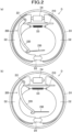
FIG. 2] FIG. 2 shows views of a drum brake and a parking brake mechanism, in which (a) ofFIG. 2 shows a state in which no brake is applied, and (b) ofFIG. 2 shows a state in which a brake is applied by the parking brake mechanism. - [
FIG. 3] FIG. 3 is a cross-sectional view showing an electric actuator of the parking brake mechanism. - [
FIG. 4] FIG. 4 is a flowchart showing a process performed by a controller. - [
FIG. 5] FIG. 5 is a flowchart showing a process at the time of an application request. - [
FIG. 6] FIG. 6 is a flowchart showing a process at the time of a release request. - [
FIG. 7] FIG. 7 is a time chart showing an example of operation of the controller when a new operation request received during an application process is a request for the application process. - [
FIG. 8] FIG. 8 is a time chart showing an example of operation of the controller when a new operation request received during the application process is a request for a release process. - [
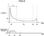
FIG. 9] FIG. 9 is a time chart showing an example of the operation of the controller when a new operation request received during the release process is a request for the release process. - [
FIG. 10] FIG. 10 is a time chart showing an example of the operation of the controller when a new operation request received during the release process is a request for the application process. - An embodiment of an electric parking brake control device will be described in detail with reference to the drawings as appropriate.
- As shown in
FIG. 1 , a vehicle CR includes drum brakes D,parking brake mechanisms 200, and a vehicle brake hydraulicpressure control apparatus 100. - The drum brakes D are provided for four wheels W, respectively. The
parking brake mechanisms 200 are mechanisms for mechanically operating the drum brakes D, and are provided for the drum brakes D provided on the two wheels W on a rear side. - The vehicle brake hydraulic
pressure control apparatus 100 appropriately controls a braking force applied to each wheel W of the vehicle CR. The vehicle brake hydraulicpressure control apparatus 100 mainly includes ahydraulic pressure unit 10 in which fluid lines (hydraulic pressure lines) and various components are provided, and acontroller 20 that appropriately controls various components in thehydraulic pressure unit 10. Thehydraulic pressure unit 10 is connected, via fluid lines, to a master cylinder MC that generates a brake hydraulic pressure by depressing a brake pedal BP, and is connected to a wheel cylinder D4 of each drum brake D via fluid lines. Thehydraulic pressure unit 10 includes a valve, a pump, and the like for controlling the brake hydraulic pressure applied to the wheel cylinders D4. - The
controller 20 is an example of the electric parking brake control device. Thecontroller 20 has a function of controlling driving and stopping of anelectric actuator 240 that operates theparking brake mechanism 200, and also has a function of controlling the valve and the pump in thehydraulic pressure unit 10.Wheel speed sensors 91 and aparking switch 92 are connected to thecontroller 20. Eachwheel speed sensor 91 detects a wheel speed of each wheel W. Theparking switch 92 switches a state of theparking brake mechanism 200 between an application state and a release state. Here, the application state refers to a state in which theparking brake mechanism 200 generates a braking force. The release state refers to a state in which theparking brake mechanism 200 releases the braking force. - The
parking switch 92 can be switched between an application position and a release position. Theparking switch 92 outputs, to thecontroller 20, an application signal for switching theparking brake mechanism 200 into the application state when theparking switch 92 is located at the application position, and outputs, to thecontroller 20, a release signal for switching theparking brake mechanism 200 into the release state when theparking switch 92 is located at the release position. - The
controller 20 includes, for example, a CPU, a RAM, a ROM, and an input/output circuit, and performs control by performing calculation processes based on an input from thewheel speed sensors 91, theparking switch 92, and the like, and a program and data stored in the ROM. - As shown in (a) and (b) of
FIG. 2 , the drumbrake D includes a drum D1 as an example of a rotation body, brake shoes D2 as examples of a friction member, a return spring D3, and the wheel cylinder D4. The drum D1 is a member having a cylindrical portion that rotates integrally with the wheel W. - The brake shoe D2 is an arc-shaped member extending along an inner circumferential surface of the drum D1, and applies a braking force to the wheel W by being pressed against the inner circumferential surface of the drum D1. Two brake shoes D2 are provided along the inner circumferential surface of the drum D1. One end portion of each of the two brake shoes D2 is rotatably supported by a support member D5, so that the two brake shoes D2 are rotatable in a direction of approaching each other and in a direction of separating from each other.
- The return spring D3 biases the other end portions of the two brake shoes D2 in a direction in which the other end portions of the two brake shoes D2 approach each other. The wheel cylinder D4 biases the two brake shoes D2 toward the inner circumferential surface of the drum D1 by the brake hydraulic pressure supplied from the
hydraulic pressure unit 10. - The
parking brake mechanism 200 includes astrut 210, aparking lever 220, awire 230, and theelectric actuator 240 shown inFIG. 3 . Thestrut 210 is engaged with the other end portions of the two brake shoes D2. - One end portion of the
parking lever 220 is rotatably supported by one brake shoe D2 by apin 221. The other end portion of theparking lever 220 is connected with thewire 230. A portion of theparking lever 220, which is between the one end portion and the other end portion and closer to the one end portion, is engaged with thestrut 210. - When the
wire 230 is pulled rightward in the drawing, theparking lever 220 rotates about thepin 221, whereby theparking lever 220 presses the other brake shoe D2 against the inner circumferential surface of the drum D1 via thestrut 210. Further, when thewire 230 is pulled, theparking lever 220 rotates about an engagement portion with thestrut 210, whereby theparking lever 220 presses the one brake shoe D2 against the inner circumferential surface of the drum D1 via thepin 221. - Accordingly, each brake shoe D2 is pressed against the inner circumferential surface of the drum D1 by a pulling operation of the
wire 230. When thewire 230 is loosened leftward in the drawing, each brake shoe D2 is away from the inner circumferential surface of the drum D1 by a bias force of the return spring D3. - As shown in
FIG. 3 , theelectric actuator 240 is a device for pulling thewire 230. Theelectric actuator 240 includes amotor 241, a plurality ofgears 242, anut 243, ascrew shaft 244, ahousing 245, aretainer 246, and a plurality of disc springs 247. - The
nut 243 is connected to themotor 241 via the plurality ofgears 242. Thenut 243 has afemale screw portion 243A that meshes with amale screw portion 244A of thescrew shaft 244. Thescrew shaft 244 is supported by thehousing 245 so as to be movable in an axial direction thereof, and thewire 230 is fixed to a distal end of thescrew shaft 244. Aflange 244B protruding in a radial direction is formed at an end portion of thescrew shaft 244 on an opposite side to the distal end thereof. - The
retainer 246 is a disc-shaped member having a hole at the center, and is engaged with theflange 244B of thescrew shaft 244 from a distal end side of thescrew shaft 244. The plurality of disc springs 247 are disposed between theflange 244B and thenut 243 in the axial direction of thescrew shaft 244. - In the
electric actuator 240, when themotor 241 rotates forward, thescrew shaft 244 moves in a direction in which thescrew shaft 244 is accommodated in thehousing 245, so that thewire 230 is pulled, and theparking brake mechanism 200 enters the application state in which parking brake is effective. When themotor 241 rotates backward, thescrew shaft 244 moves in a direction in which thescrew shaft 244 protrudes from thehousing 245, so that thewire 230 is loosened, and theparking brake mechanism 200 enters the release state in which the parking brake is released. In the release state, the plurality of disc springs 247 are sandwiched between theretainer 246 and thenut 243 in a deformed state. - In the following description, a position of the
screw shaft 244 when theparking brake mechanism 200 is in the application state is also referred to as an "application position", and a position of thescrew shaft 244 when theparking brake mechanism 200 is in the release state is also referred to as a "release position". Specifically, the release position is a position shown inFIG. 3 , and the application position is a position at which thescrew shaft 244 shown inFIG. 3 is moved to a right side in the drawing from the position in the drawing. - The
controller 20 controls forward rotation, backward rotation, and stop of themotor 241 based on a signal from theparking switch 92. Thecontroller 20 has a function of performing an application process and a release process. In the following description, the output of the application signal from theparking switch 92 is also referred to as a "request for the application process", the output of the release signal from theparking switch 92 is also referred to as a "request for the release process", and these requests for processes are also collectively referred to as an "operation request". - The application process is a process for driving the
electric actuator 240 such that theparking brake mechanism 200 is in the application state. In other words, the application process is a process for controlling theelectric actuator 240 to move the brake shoe D2 in a direction in which the brake shoe D2 is pressed against the drum D1. Specifically, when receiving a request for the application process, thecontroller 20 rotates themotor 241 forward to move thescrew shaft 244 to the application position, thereby bringing theparking brake mechanism 200 into the application state. - Specifically, as shown in
FIG. 7 , when receiving a request for the application process (A), thecontroller 20 starts the application process by supplying a current for rotating themotor 241 forward to the motor 241 (time t1). At the start of energization of themotor 241, an inrush current is generated, but the inrush current converges after a predetermined time (time t2). When the inrush current converges, themotor 241 starts to rotate. - Accordingly, the
screw shaft 244 starts to move from the release position toward the application position. As thescrew shaft 244 moves from the release position toward the application position, a load applied to thescrew shaft 244 from thedisc spring 247 gradually decreases, and thus the current gradually decreases. When thescrew shaft 244 is away from theretainer 246, no load is applied to the screw shaft 244 (time t3), and then the current is constant. - Thereafter, when the brake shoe D2 comes into contact with the drum D1 (time t4), the load applied to the
screw shaft 244 gradually increases, and the current supplied to themotor 241 increases. Thereafter, when the current is equal to or larger than an application threshold IA (time t5), thecontroller 20 stops the energization and completes the application process. - The release process is a process for driving the
electric actuator 240 such that theparking brake mechanism 200 is in the release state. In other words, the release process is a process for controlling theelectric actuator 240 to move the brake shoe D2 in a direction away from the drum D1. Specifically, when receiving a request for the release process, thecontroller 20 rotates themotor 241 backward to move thescrew shaft 244 to the release position, thereby bringing theparking brake mechanism 200 into the release state. - Specifically, as shown in
FIG. 9 , when receiving a request for the release process (R), thecontroller 20 starts the release process by supplying a current for rotating themotor 241 backward to the motor 241 (time t51) . At the start of energization of themotor 241, an inrush current is generated, but the inrush current converges after a predetermined time (time t52) . When the inrush current converges, themotor 241 starts to rotate. - Accordingly, the
screw shaft 244 moves from the application position toward the release position, and the brake shoe D2 moves in the direction away from the drum D1. As thescrew shaft 244 moves from the application position toward the release position, a load applied to thescrew shaft 244 from the brake shoe D2 gradually decreases, and thus the current gradually decreases. When the brake shoe D2 is away from the drum D1, no load is applied to the screw shaft 244 (time t53), and then the current is constant. - Thereafter, when the
screw shaft 244 comes into contact with the retainer 246 (time t54), a load applied to thescrew shaft 244 from thedisc spring 247 gradually increases, and the current supplied to themotor 241 increases. Thereafter, when the current is equal to or larger than a release threshold IR (time t55), thecontroller 20 stops the energization and completes the release process. - Even when receiving a new operation request for operating the
electric actuator 240 during a period from the start of the application process or the release process to the completion of the process, thecontroller 20 is configured not to change the operation of theelectric actuator 240 based on the operation request. When receiving a new operation request for performing a process different from the current process during the period from the start of the application process or the release process to the completion of the process, thecontroller 20 is configured to perform a process based on the new operation request after the completion of the current process (seeFIGS. 8 and10 ). - Further, when receiving a new operation request for performing the same process as the current process during the period from the start of the application process or the release process to the completion of the process, the
controller 20 is configured not to perform a process based on the new operation request after the completion of the current process (SeeFIGS. 7 and9 ). When receiving a plurality of new operation requests during the period from the start of the application process or the release process to the completion of the process, thecontroller 20 is configured to control theelectric actuator 240 based on a last received operation request among the plurality of new operation requests after the completion of the current process. - Next, processes of the
controller 20 will be described in detail with reference toFIGS. 4 to 6 . Thecontroller 20 repeatedly executes the process shown inFIG. 4 at all times. - In the process shown in
FIG. 4 , thecontroller 20 first determines whether an operation request for operating theelectric actuator 240 is issued (S1). When it is determined in step S1 that the operation request is not issued (No), thecontroller 20 ends the present process. - When it is determined in step S1 that the operation request is issued (Yes), the
controller 20 determines whether the operation request is a request for the application process (S2). When it is determined in step S2 that the operation request is a request for the application process (Yes), thecontroller 20 performs a process at the time of an application request (S3). Here, the process at the time of an application request is a process shown inFIG. 5 performed when the request for the application process is received, and will be described in detail later. - When it is determined in step S2 that the operation request is not a request for the application process (Yes), the
controller 20 performs a process at the time of a release request (S4). Here, the process at the time of a release request is a process shown inFIG. 6 performed when a request for the release process is received, and will be described in detail later. After step S3 or step S4, thecontroller 20 ends the present process. - As shown in
FIG. 5 , in the process at the time of an application request, thecontroller 20 performs an application process shown in steps S11 to S15, and then performs a process shown in steps S16 to S18 for controlling theelectric actuator 240 based on a new operation request received during the application process. Specifically, in the process at the time of an application request, thecontroller 20 first starts energization for the application process (S11). Specifically, in step S11, thecontroller 20 supplies a current for rotating themotor 241 forward to themotor 241. - After step S11, the
controller 20 determines whether a new operation request is present (S12) . When it is determined in step S12 that a new operation request is present (Yes), thecontroller 20 stores the new operation request (S13). - After step S13 or when it is determined in step S12 that no new operation request is present (No), the
controller 20 determines whether a current generated after the lapse of a first time period T1 (seeFIG. 7 ) from the start of the application process is equal to or larger than the application threshold IA (S14) . Specifically, in step S14, thecontroller 20 determines whether both a condition that the first time period T1 has elapsed from the start of the application process and a condition that the current is equal to or larger than the application threshold IA are satisfied. Here, the first time period T1 is a time period from the start of the application process until the current becomes sufficiently smaller than the application threshold IA after the inrush current generated at the start is converged, and is appropriately set by an experiment, a simulation, or the like. - When it is determined in step S14 that the current generated after the lapse of the first time period T1 is not equal to or larger than the application threshold IA (No), the
controller 20 returns to the process in step S12. When it is determined in step S14 that the current generated after the lapse of the first time period T1 is equal to or larger than the application threshold IA (Yes), thecontroller 20 turns off the energization and completes the application process (S15) . - After step S15, the
controller 20 determines whether a new operation request is present during the application process completed this time (S16) . When it is determined in step S16 that the new operation request is present (Yes), thecontroller 20 determines whether the new operation request is a request for the release process (S17). Specifically, when one new operation request is received during the application process, thecontroller 20 determines whether the operation request is the request for the release process (S17). - When it is determined in step S17 that the new operation request is the request for the release process (Yes), the
controller 20 performs a process at the time of a release request (S18) and ends the present process. When it is determined as No in step S16 or step S17, thecontroller 20 ends the present process as it is. Therefore, when the new operation request is a request for the application process in step S17, thecontroller 20 ends the present process without performing the application process. - When receiving a plurality of operation requests during the application process, the
controller 20 determines whether the last received operation request among the plurality of new operation requests is a request for the release process (S17) . - Any method may be used to specify the last received operation request from the plurality of new operation requests . For example, in step S13, the plurality of new operation requests and times at which the operation requests are received may be stored in association, and the last received operation request may be specified based on the times. In step S13, the last received operation request may be specified by overwriting the new operation request stored last time with the new operation request. The stored new operation request may be reset, for example, at the start of the application process or at the start of the release process.
- As shown in
FIG. 6 , in the process at the time of a release request, thecontroller 20 performs a release process shown in steps S31 to S35, and then performs a process shown in steps S36 to S38 for controlling theelectric actuator 240 based on a new operation request received during the release process. Specifically, in the process at the time of a release request, thecontroller 20 first starts energization for the release process (S31). Specifically, in step S31, thecontroller 20 supplies a current for rotating themotor 241 backward to themotor 241. - After step S31, the
controller 20 determines whether a new operation request is present (S32) . When it is determined in step S32 that the new operation request is present (Yes), thecontroller 20 stores the new operation request (S33). - After step S33 or when it is determined in step S32 that no new operation request is present (No), the
controller 20 determines whether a current generated after the lapse of a second time period T2 (seeFIG. 9 ) from the start of the release process is equal to or larger than the release threshold IR (S34) . Specifically, in step S34, thecontroller 20 determines whether both a condition that the second time period T2 has elapsed from the start of the release process and a condition that the current is equal to or larger than the release threshold IR are satisfied. Here, the second time period T2 is a time period from the start of the release process until the current becomes sufficiently smaller than the release threshold IR after the inrush current generated at the start is converged, and is appropriately set by an experiment, a simulation, or the like. - When it is determined in step S34 that the current generated after the lapse of the second time period T2 is not equal to or larger than the release threshold IR (No), the
controller 20 returns to the process in step S32. When it is determined in step S34 that the current generated after the lapse of the second time period T2 is equal to or larger than the release threshold IR (Yes), thecontroller 20 turns off the energization and completes the release process (S35). - After step S35, the
controller 20 determines whether a new operation request is issued during the release process completed this time (S36) . When it is determined in step S36 that the new operation request is issued (Yes), thecontroller 20 determines whether the new operation request is a request for the application process (S37) . Specifically, when one new operation request is received during the release process, thecontroller 20 determines whether the operation request is the request for the application process (S37). - When it is determined in step S37 that the new operation request is a request for the application process (Yes), the
controller 20 performs a process at the time of an application request (S38) and ends the present process. When it is determined as No in step S36 or step S37, thecontroller 20 ends the present process as it is. Therefore, when the new operation request is a request for the release process in step S37, thecontroller 20 ends the present process without performing the release process. - When receiving a plurality of operation requests during the release process, the
controller 20 determines whether the last received operation request among the plurality of new operation requests is a request for the application process (S37). - A method for specifying the last received operation request from a plurality of new operation requests and a method for resetting a new operation request may be performed in the same manner as the process at the time of an application request.
- Next, an example of the operation of the
controller 20 will be described in detail with reference toFIGS. 7 to 10 . - As shown in
FIG. 7 , when receiving a request for the application process (A), thecontroller 20 starts an application process (time t1). During the application process (t1 to t5), as shown by solid lines in the drawing, when a plurality of new operation requests are received and the last received operation request is the request for the application process (A) (time t11), thecontroller 20 does not perform an application process based on a new request for the application process (A) after the completion of the application process (time t5). During the application process (t1 to t5), as shown by two-dot chain lines in the drawing, even when only one request of the application process (A) is received as a new operation request (time t12), thecontroller 20 does not perform an application process based on the new request for the application process (A) after the completion of the application process (time t5). - As shown in
FIG. 8 , during the application process (t1 to t5), as shown by solid lines in the drawing, when a plurality of new operation requests are received and the last received operation request is the request for the release process (R) (time t21), thecontroller 20 performs a release process (time t23) after the completion of the application process (time t5) . During the application process (t1 to t5), as shown by two-dot chain lines in the drawing, even when only one request for the release process (R) is received as a new operation request (time t22), thecontroller 20 performs a release process (time t23) after the completion of the application process (time t5). - As shown in
FIG. 9 , when receiving the request for the release process (R), thecontroller 20 starts a release process (time t51) . During the release process (t51 to t55), as shown by solid lines in the drawing, when a plurality of new operation requests are received and the last received operation request is the request for the release process (R) (time t61), thecontroller 20 does not perform a release process based on a new request for the release process (R) after the completion of the release process (time t5). During the release process (t51 to t55), as shown by two-dot chain lines in the drawing, even when only one request for the release process (R) is received as a new operation request (time t62), thecontroller 20 does not perform a release process based on the new request for the release process (R) after the completion of the release process (time t55). - As shown in
FIG. 10 , during the release process (t51 to t55), as shown by solid lines in the drawing, when a plurality of new operation requests are received and the last received operation request is the request for the application process (A) (time t71), thecontroller 20 performs an application process (time t73) after the completion of the release process (time t55) . During the release process (t51 to t55), as shown by two-dot chain lines in the drawing, even when only one request for the application process (A) is received as a new operation request (time t72), thecontroller 20 performs an application process (time t73) after the completion of the release process (time t55). - According to the above, the following effects can be obtained in the present embodiment.
- Even when a new operation request is received during a period from the start of the application process or the release process to the completion of the process, the operation of the
electric actuator 240 is not changed based on the operation request. Therefore, the operation of theelectric actuator 240 can be accurately determined. - When an operation request for performing a process different from a current process is issued during the application process or the release process, a process based on the new operation request is performed after the completion of the current process. Therefore, it is possible to quickly respond to a request of a user.
- According to this configuration, when an operation request for performing the same process as the current process is issued during the application process or the release process, a process based on the new operation request is not performed after the completion of the current process. Therefore, it is possible to prevent the same process from being repeatedly performed.
- Since the
electric actuator 240 is controlled based on the last received operation request among the plurality of new operation requests received during the application process or the release process, theelectric actuator 240 can be controlled to correspond to the intention of the user. - The above-described embodiment may be modified into various forms as exemplified below.
- In the above embodiment, the
controller 20 of the vehicle brake hydraulicpressure control apparatus 100 is given as an example of the electric parking brake control device, but a control device other than the vehicle brake hydraulic pressure control apparatus, for example, an electronic control unit (ECU) of a vehicle may be used as the electric parking brake control device. - In the above-described embodiment, the
parking brake mechanism 200 installed in the drum brake D is given as an example, but a parking brake mechanism installed in a disc brake may be used, for example. In this case, a rotor that rotates integrally with the wheel corresponds to the rotation body, and a pad that is pressed against the rotor corresponds to the friction member. - The elements described in the above-described embodiment and the modification may be combined as desired.
Claims (4)
- An electric parking brake control device for performing an application process for controlling an electric actuator to move a friction member in a direction of being pressed against a rotation body that rotates integrally with a wheel, and a release process for controlling the electric actuator to move the friction member in a direction away from the rotation body, wherein
even when a new operation request for operating the electric actuator is received during a period from the start of the application process or the release process to the completion of the process, operation of the electric actuator is not changed based on the operation request. - The electric parking brake control device according to claim 1, wherein
when a new operation request for performing a process different from a current process is received during the period from the start of the application process or the release process to the completion of the process, a process based on the new operation request is performed after the completion of the current process. - The electric parking brake control device according to claim 1 or 2, wherein
when a new operation request for performing the same process as the current process is received during the period from the start of the application process or the release process to the completion of the process, a process based on the new operation request is not performed after the completion of the current process. - The electric parking brake control device according to claim 2 or 3, wherein
when a plurality of new operation requests are received during the period from the start of the application process or the release process to the completion of the process, the electric actuator is controlled based on a last received operation request among the plurality of new operation requests after the completion of the current process.
Applications Claiming Priority (2)
| Application Number | Priority Date | Filing Date | Title |
|---|---|---|---|
| JP2020117242 | 2020-07-07 | ||
| PCT/JP2021/024498 WO2022009730A1 (en) | 2020-07-07 | 2021-06-29 | Electric parking brake control device |
Publications (3)
| Publication Number | Publication Date |
|---|---|
| EP4180290A1 true EP4180290A1 (en) | 2023-05-17 |
| EP4180290A4 EP4180290A4 (en) | 2023-12-06 |
| EP4180290B1 EP4180290B1 (en) | 2025-11-12 |
Family
ID=79553072
Family Applications (1)
| Application Number | Title | Priority Date | Filing Date |
|---|---|---|---|
| EP21837848.7A Active EP4180290B1 (en) | 2020-07-07 | 2021-06-29 | Electric parking brake control device |
Country Status (6)
| Country | Link |
|---|---|
| US (1) | US12427968B2 (en) |
| EP (1) | EP4180290B1 (en) |
| JP (1) | JP7488630B2 (en) |
| KR (1) | KR102774031B1 (en) |
| CN (1) | CN115884905A (en) |
| WO (1) | WO2022009730A1 (en) |
Family Cites Families (25)
| Publication number | Priority date | Publication date | Assignee | Title |
|---|---|---|---|---|
| JPH01197160A (en) * | 1988-02-01 | 1989-08-08 | Mazda Motor Corp | Brake controller of vehicle |
| JPH09240447A (en) * | 1996-03-11 | 1997-09-16 | Toyota Motor Corp | Vehicle motion control device |
| JP2004122838A (en) * | 2002-08-07 | 2004-04-22 | Asmo Co Ltd | Electric parking brake system and method for controlling electric parking brake system |
| DE102008064077A1 (en) * | 2008-12-19 | 2010-07-01 | Wabco Gmbh | Actuating device and method for actuating such an actuator |
| US8776958B2 (en) * | 2009-02-27 | 2014-07-15 | Toyota Jidosha Kabushiki Kaisha | Brake apparatus |
| JP5673639B2 (en) * | 2012-03-22 | 2015-02-18 | 株式会社アドヴィックス | Electric parking brake control device |
| JP5737224B2 (en) * | 2012-05-28 | 2015-06-17 | 株式会社アドヴィックス | Brake device for vehicle |
| JP5898035B2 (en) * | 2012-09-28 | 2016-04-06 | 日立オートモティブシステムズ株式会社 | Disc brake device |
| DE102012223178B4 (en) * | 2012-12-14 | 2025-01-23 | Robert Bosch Gmbh | Method for actuating a parking brake with an electric motor-driven parking brake mechanism |
| JP6289855B2 (en) * | 2013-10-10 | 2018-03-07 | Ntn株式会社 | Electric brake device with parking function |
| JP6297883B2 (en) * | 2014-03-28 | 2018-03-20 | マツダ株式会社 | Electric brake device |
| JP6357045B2 (en) * | 2014-07-31 | 2018-07-11 | 日立オートモティブシステムズ株式会社 | Brake device |
| JP6397694B2 (en) * | 2014-08-25 | 2018-09-26 | 日立オートモティブシステムズ株式会社 | Brake device |
| CN107249941B (en) * | 2014-12-27 | 2019-12-27 | 马自达汽车株式会社 | Brake device |
| JP6457260B2 (en) * | 2014-12-27 | 2019-01-23 | 日立オートモティブシステムズ株式会社 | Brake device |
| DE112015005833T5 (en) * | 2014-12-27 | 2017-09-28 | Hitachi Automotive Systems, Ltd. | braking means |
| JP6372003B2 (en) * | 2014-12-27 | 2018-08-15 | 日立オートモティブシステムズ株式会社 | Electric brake system |
| DE112016001571T5 (en) * | 2015-03-31 | 2017-12-14 | Hitachi Automotive Systems, Ltd. | Brake control device |
| JP2016203871A (en) * | 2015-04-24 | 2016-12-08 | トヨタ自動車株式会社 | Vehicle engine start control system |
| JP6298008B2 (en) * | 2015-04-24 | 2018-03-20 | トヨタ自動車株式会社 | Vehicle engine start control system |
| JP2016203872A (en) * | 2015-04-24 | 2016-12-08 | トヨタ自動車株式会社 | Engine start control system for vehicle |
| US10399553B2 (en) * | 2015-08-31 | 2019-09-03 | Hitachi Automotive Systems, Ltd. | Operating switch and parking brake control device |
| JP6898995B2 (en) * | 2017-09-27 | 2021-07-07 | 日立Astemo株式会社 | Brake device, vehicle control device |
| JP7136662B2 (en) * | 2018-11-01 | 2022-09-13 | 日立Astemo株式会社 | electric parking brake device |
| CN113242823A (en) * | 2018-12-26 | 2021-08-10 | 日立安斯泰莫株式会社 | Electric brake device |
-
2021
- 2021-06-29 US US18/004,320 patent/US12427968B2/en active Active
- 2021-06-29 KR KR1020227044749A patent/KR102774031B1/en active Active
- 2021-06-29 CN CN202180048344.8A patent/CN115884905A/en active Pending
- 2021-06-29 WO PCT/JP2021/024498 patent/WO2022009730A1/en not_active Ceased
- 2021-06-29 EP EP21837848.7A patent/EP4180290B1/en active Active
- 2021-06-29 JP JP2022535036A patent/JP7488630B2/en active Active
Also Published As
| Publication number | Publication date |
|---|---|
| KR20230013121A (en) | 2023-01-26 |
| EP4180290A4 (en) | 2023-12-06 |
| CN115884905A (en) | 2023-03-31 |
| JP7488630B2 (en) | 2024-05-22 |
| JPWO2022009730A1 (en) | 2022-01-13 |
| US20230249659A1 (en) | 2023-08-10 |
| WO2022009730A1 (en) | 2022-01-13 |
| US12427968B2 (en) | 2025-09-30 |
| KR102774031B1 (en) | 2025-02-26 |
| EP4180290B1 (en) | 2025-11-12 |
Similar Documents
| Publication | Publication Date | Title |
|---|---|---|
| JP5737224B2 (en) | Brake device for vehicle | |
| EP2687745B1 (en) | Brake device | |
| JP6297883B2 (en) | Electric brake device | |
| US10308229B2 (en) | Electronic control brake system and method for controlling the same | |
| WO2010024307A1 (en) | Parking brake control device | |
| CN107249941A (en) | Braking device | |
| JP6743780B2 (en) | Braking control device | |
| EP4180290B1 (en) | Electric parking brake control device | |
| US11001235B2 (en) | Vehicle control device | |
| JP7425648B2 (en) | Electric parking brake control device | |
| JP7135410B2 (en) | Braking control device | |
| JP7431972B2 (en) | Electric parking brake control device | |
| US20230265900A1 (en) | Brake system and method for controlling the same | |
| JP7425651B2 (en) | Electric parking brake control device | |
| CN117836181A (en) | Parking brake device with improved command | |
| WO2018181786A1 (en) | Vehicular brake device | |
| JP7425650B2 (en) | Electric parking brake control device | |
| JP7425649B2 (en) | Electric parking brake control device | |
| JP2025067304A (en) | Brake system for vehicle | |
| JP7352502B2 (en) | Electric parking brake control device | |
| JP2020116967A (en) | Brake control device | |
| JP7149212B2 (en) | electric brake device | |
| WO2025037365A1 (en) | Brake device control apparatus and control method | |
| JP2024070656A (en) | Vehicle control device |
Legal Events
| Date | Code | Title | Description |
|---|---|---|---|
| STAA | Information on the status of an ep patent application or granted ep patent |
Free format text: STATUS: THE INTERNATIONAL PUBLICATION HAS BEEN MADE |
|
| PUAI | Public reference made under article 153(3) epc to a published international application that has entered the european phase |
Free format text: ORIGINAL CODE: 0009012 |
|
| STAA | Information on the status of an ep patent application or granted ep patent |
Free format text: STATUS: REQUEST FOR EXAMINATION WAS MADE |
|
| 17P | Request for examination filed |
Effective date: 20230117 |
|
| AK | Designated contracting states |
Kind code of ref document: A1 Designated state(s): AL AT BE BG CH CY CZ DE DK EE ES FI FR GB GR HR HU IE IS IT LI LT LU LV MC MK MT NL NO PL PT RO RS SE SI SK SM TR |
|
| DAV | Request for validation of the european patent (deleted) | ||
| DAX | Request for extension of the european patent (deleted) | ||
| A4 | Supplementary search report drawn up and despatched |
Effective date: 20231107 |
|
| RIC1 | Information provided on ipc code assigned before grant |
Ipc: B60T 17/18 20060101ALI20231101BHEP Ipc: B60T 8/00 20060101ALI20231101BHEP Ipc: B60T 13/74 20060101AFI20231101BHEP |
|
| GRAP | Despatch of communication of intention to grant a patent |
Free format text: ORIGINAL CODE: EPIDOSNIGR1 |
|
| STAA | Information on the status of an ep patent application or granted ep patent |
Free format text: STATUS: GRANT OF PATENT IS INTENDED |
|
| INTG | Intention to grant announced |
Effective date: 20250707 |
|
| RAP3 | Party data changed (applicant data changed or rights of an application transferred) |
Owner name: ASTEMO, LTD. |
|
| GRAS | Grant fee paid |
Free format text: ORIGINAL CODE: EPIDOSNIGR3 |
|
| GRAA | (expected) grant |
Free format text: ORIGINAL CODE: 0009210 |
|
| STAA | Information on the status of an ep patent application or granted ep patent |
Free format text: STATUS: THE PATENT HAS BEEN GRANTED |
|
| AK | Designated contracting states |
Kind code of ref document: B1 Designated state(s): AL AT BE BG CH CY CZ DE DK EE ES FI FR GB GR HR HU IE IS IT LI LT LU LV MC MK MT NL NO PL PT RO RS SE SI SK SM TR |
|
| REG | Reference to a national code |
Ref country code: CH Ref legal event code: F10 Free format text: ST27 STATUS EVENT CODE: U-0-0-F10-F00 (AS PROVIDED BY THE NATIONAL OFFICE) Effective date: 20251112 Ref country code: GB Ref legal event code: FG4D |
|
| REG | Reference to a national code |
Ref country code: DE Ref legal event code: R096 Ref document number: 602021042372 Country of ref document: DE |
|
| REG | Reference to a national code |
Ref country code: IE Ref legal event code: FG4D |
|
| PG25 | Lapsed in a contracting state [announced via postgrant information from national office to epo] |
Ref country code: ES Free format text: LAPSE BECAUSE OF FAILURE TO SUBMIT A TRANSLATION OF THE DESCRIPTION OR TO PAY THE FEE WITHIN THE PRESCRIBED TIME-LIMIT Effective date: 20251112 |
|
| REG | Reference to a national code |
Ref country code: LT Ref legal event code: MG9D |
|
| PG25 | Lapsed in a contracting state [announced via postgrant information from national office to epo] |
Ref country code: NO Free format text: LAPSE BECAUSE OF FAILURE TO SUBMIT A TRANSLATION OF THE DESCRIPTION OR TO PAY THE FEE WITHIN THE PRESCRIBED TIME-LIMIT Effective date: 20260212 |
|
| PG25 | Lapsed in a contracting state [announced via postgrant information from national office to epo] |
Ref country code: FI Free format text: LAPSE BECAUSE OF FAILURE TO SUBMIT A TRANSLATION OF THE DESCRIPTION OR TO PAY THE FEE WITHIN THE PRESCRIBED TIME-LIMIT Effective date: 20251112 Ref country code: HR Free format text: LAPSE BECAUSE OF FAILURE TO SUBMIT A TRANSLATION OF THE DESCRIPTION OR TO PAY THE FEE WITHIN THE PRESCRIBED TIME-LIMIT Effective date: 20251112 Ref country code: AT Free format text: LAPSE BECAUSE OF FAILURE TO SUBMIT A TRANSLATION OF THE DESCRIPTION OR TO PAY THE FEE WITHIN THE PRESCRIBED TIME-LIMIT Effective date: 20251112 |
|
| REG | Reference to a national code |
Ref country code: AT Ref legal event code: MK05 Ref document number: 1856518 Country of ref document: AT Kind code of ref document: T Effective date: 20251112 |
|
| PG25 | Lapsed in a contracting state [announced via postgrant information from national office to epo] |
Ref country code: NL Free format text: LAPSE BECAUSE OF FAILURE TO SUBMIT A TRANSLATION OF THE DESCRIPTION OR TO PAY THE FEE WITHIN THE PRESCRIBED TIME-LIMIT Effective date: 20251112 |
|
| PG25 | Lapsed in a contracting state [announced via postgrant information from national office to epo] |
Ref country code: RS Free format text: LAPSE BECAUSE OF FAILURE TO SUBMIT A TRANSLATION OF THE DESCRIPTION OR TO PAY THE FEE WITHIN THE PRESCRIBED TIME-LIMIT Effective date: 20260212 |
|
| PG25 | Lapsed in a contracting state [announced via postgrant information from national office to epo] |
Ref country code: IS Free format text: LAPSE BECAUSE OF FAILURE TO SUBMIT A TRANSLATION OF THE DESCRIPTION OR TO PAY THE FEE WITHIN THE PRESCRIBED TIME-LIMIT Effective date: 20260312 |
|
| PG25 | Lapsed in a contracting state [announced via postgrant information from national office to epo] |
Ref country code: PT Free format text: LAPSE BECAUSE OF FAILURE TO SUBMIT A TRANSLATION OF THE DESCRIPTION OR TO PAY THE FEE WITHIN THE PRESCRIBED TIME-LIMIT Effective date: 20260312 |
|
| PG25 | Lapsed in a contracting state [announced via postgrant information from national office to epo] |
Ref country code: PL Free format text: LAPSE BECAUSE OF FAILURE TO SUBMIT A TRANSLATION OF THE DESCRIPTION OR TO PAY THE FEE WITHIN THE PRESCRIBED TIME-LIMIT Effective date: 20251112 |
|
| PG25 | Lapsed in a contracting state [announced via postgrant information from national office to epo] |
Ref country code: LV Free format text: LAPSE BECAUSE OF FAILURE TO SUBMIT A TRANSLATION OF THE DESCRIPTION OR TO PAY THE FEE WITHIN THE PRESCRIBED TIME-LIMIT Effective date: 20251112 |
|
| PG25 | Lapsed in a contracting state [announced via postgrant information from national office to epo] |
Ref country code: BG Free format text: LAPSE BECAUSE OF FAILURE TO SUBMIT A TRANSLATION OF THE DESCRIPTION OR TO PAY THE FEE WITHIN THE PRESCRIBED TIME-LIMIT Effective date: 20251112 |
|
| PG25 | Lapsed in a contracting state [announced via postgrant information from national office to epo] |
Ref country code: LT Free format text: LAPSE BECAUSE OF FAILURE TO SUBMIT A TRANSLATION OF THE DESCRIPTION OR TO PAY THE FEE WITHIN THE PRESCRIBED TIME-LIMIT Effective date: 20251112 |
|
| PG25 | Lapsed in a contracting state [announced via postgrant information from national office to epo] |
Ref country code: SM Free format text: LAPSE BECAUSE OF FAILURE TO SUBMIT A TRANSLATION OF THE DESCRIPTION OR TO PAY THE FEE WITHIN THE PRESCRIBED TIME-LIMIT Effective date: 20251112 |
|
| PG25 | Lapsed in a contracting state [announced via postgrant information from national office to epo] |
Ref country code: DK Free format text: LAPSE BECAUSE OF FAILURE TO SUBMIT A TRANSLATION OF THE DESCRIPTION OR TO PAY THE FEE WITHIN THE PRESCRIBED TIME-LIMIT Effective date: 20251112 |
|
| PG25 | Lapsed in a contracting state [announced via postgrant information from national office to epo] |
Ref country code: IT Free format text: LAPSE BECAUSE OF FAILURE TO SUBMIT A TRANSLATION OF THE DESCRIPTION OR TO PAY THE FEE WITHIN THE PRESCRIBED TIME-LIMIT Effective date: 20251112 |
|
| PGFP | Annual fee paid to national office [announced via postgrant information from national office to epo] |
Ref country code: DE Payment date: 20260622 Year of fee payment: 6 |
|
| PG25 | Lapsed in a contracting state [announced via postgrant information from national office to epo] |
Ref country code: EE Free format text: LAPSE BECAUSE OF FAILURE TO SUBMIT A TRANSLATION OF THE DESCRIPTION OR TO PAY THE FEE WITHIN THE PRESCRIBED TIME-LIMIT Effective date: 20251112 |
|
| PG25 | Lapsed in a contracting state [announced via postgrant information from national office to epo] |
Ref country code: CZ Free format text: LAPSE BECAUSE OF FAILURE TO SUBMIT A TRANSLATION OF THE DESCRIPTION OR TO PAY THE FEE WITHIN THE PRESCRIBED TIME-LIMIT Effective date: 20251112 |
|
| PGFP | Annual fee paid to national office [announced via postgrant information from national office to epo] |
Ref country code: FR Payment date: 20260626 Year of fee payment: 6 |
|
| PG25 | Lapsed in a contracting state [announced via postgrant information from national office to epo] |
Ref country code: SK Free format text: LAPSE BECAUSE OF FAILURE TO SUBMIT A TRANSLATION OF THE DESCRIPTION OR TO PAY THE FEE WITHIN THE PRESCRIBED TIME-LIMIT Effective date: 20251112 |
|
| PG25 | Lapsed in a contracting state [announced via postgrant information from national office to epo] |
Ref country code: SE Free format text: LAPSE BECAUSE OF FAILURE TO SUBMIT A TRANSLATION OF THE DESCRIPTION OR TO PAY THE FEE WITHIN THE PRESCRIBED TIME-LIMIT Effective date: 20251112 |