EP4180276A1 - Collapsible rear bumper inner support, rear bumper, and vehicle - Google Patents
Collapsible rear bumper inner support, rear bumper, and vehicle Download PDFInfo
- Publication number
- EP4180276A1 EP4180276A1 EP20943936.3A EP20943936A EP4180276A1 EP 4180276 A1 EP4180276 A1 EP 4180276A1 EP 20943936 A EP20943936 A EP 20943936A EP 4180276 A1 EP4180276 A1 EP 4180276A1
- Authority
- EP
- European Patent Office
- Prior art keywords
- support
- rear bumper
- inner support
- face
- collapsible
- Prior art date
- Legal status (The legal status is an assumption and is not a legal conclusion. Google has not performed a legal analysis and makes no representation as to the accuracy of the status listed.)
- Granted
Links
Images


Classifications
-
- B—PERFORMING OPERATIONS; TRANSPORTING
- B60—VEHICLES IN GENERAL
- B60R—VEHICLES, VEHICLE FITTINGS, OR VEHICLE PARTS, NOT OTHERWISE PROVIDED FOR
- B60R19/00—Wheel guards; Radiator guards, e.g. grilles; Obstruction removers; Fittings damping bouncing force in collisions
- B60R19/02—Bumpers, i.e. impact receiving or absorbing members for protecting vehicles or fending off blows from other vehicles or objects
- B60R19/18—Bumpers, i.e. impact receiving or absorbing members for protecting vehicles or fending off blows from other vehicles or objects characterised by the cross-section; Means within the bumper to absorb impact
-
- B—PERFORMING OPERATIONS; TRANSPORTING
- B60—VEHICLES IN GENERAL
- B60R—VEHICLES, VEHICLE FITTINGS, OR VEHICLE PARTS, NOT OTHERWISE PROVIDED FOR
- B60R19/00—Wheel guards; Radiator guards, e.g. grilles; Obstruction removers; Fittings damping bouncing force in collisions
- B60R19/02—Bumpers, i.e. impact receiving or absorbing members for protecting vehicles or fending off blows from other vehicles or objects
- B60R19/04—Bumpers, i.e. impact receiving or absorbing members for protecting vehicles or fending off blows from other vehicles or objects formed from more than one section in a side-by-side arrangement
- B60R19/12—Bumpers, i.e. impact receiving or absorbing members for protecting vehicles or fending off blows from other vehicles or objects formed from more than one section in a side-by-side arrangement vertically spaced
-
- B—PERFORMING OPERATIONS; TRANSPORTING
- B60—VEHICLES IN GENERAL
- B60R—VEHICLES, VEHICLE FITTINGS, OR VEHICLE PARTS, NOT OTHERWISE PROVIDED FOR
- B60R19/00—Wheel guards; Radiator guards, e.g. grilles; Obstruction removers; Fittings damping bouncing force in collisions
- B60R19/02—Bumpers, i.e. impact receiving or absorbing members for protecting vehicles or fending off blows from other vehicles or objects
- B60R19/18—Bumpers, i.e. impact receiving or absorbing members for protecting vehicles or fending off blows from other vehicles or objects characterised by the cross-section; Means within the bumper to absorb impact
- B60R2019/186—Additional energy absorbing means supported on bumber beams, e.g. cellular structures or material
Definitions
- the fastener is a flange nut.
- the rear bumper inner support in this embodiment absorbs the impact energy through the rapid collapse and fragmentation of the collapse rib 12, and protects the rear wall metal panel 2 of the vehicle body from deformation. Moreover, compared with the rear bumper inner support in the prior art, the rear bumper inner support in this embodiment is lighter in weight and lower in cost.
- the support front face 14 is provided a plurality of upper installation structures 15, for connecting with the rear wall metal panel of the vehicle body.
- the structure of the upper installation structure 15 can be set according to actual needs.
- the upper installation structure 15 is provided with a first installation hole, and bolts welded on the rear wall metal panel 2 of the vehicle body pass through the first installation holes and are fixedly connected by fasteners.
- the fasteners may be flange nuts, and those of ordinary skill in the art may use other fasteners to realize the connection between the support front face 14 and the rear wall metal panel 2 of the vehicle body according to requirements.
Landscapes
- Engineering & Computer Science (AREA)
- Mechanical Engineering (AREA)
- Body Structure For Vehicles (AREA)
Abstract
Description
- The present disclosure relates to vehicle components, in particular to a collapsible rear bumper inner support, a rear bumper and a vehicle.
- With the development of the automobile market, new technologies and new functions are constantly emerging, consumers will pay more and more attention to vehicle safety, and vehicle insurance costs are gradually linked to vehicle maintenance costs. Currently, there are professional insurance institutions in many countries around the world to carry out research in this area, such as China Insurance Research Institute (C-IASI) and Insurance Institute for Highway Safety (IIHS) in the United States, Thatcham Research in Britain, and AZT Automotive GmbH in Germany, all of which are affiliated to an international institution named Automobile Repair Research Committee of Research Council of Automobile Repairs (RCAR). It was jointly established by the insurance industry in various countries to develop testing standards and study the cost of vehicle maintenance. At present, these institutions all include collision tests on crashworthiness and maintenance economy. Its crash score will be directly applied to the insurance pricing of the vehicle by the insurance company. Consumers will also refer to the scores when purchasing vehicles to find out whether the subsequent maintenance costs of the vehicle are within their own tolerance. For OEMs, they need to improve the safety performance of their vehicles and reduce the damage to key components of the vehicle.
- For the collision test of the rear portion of the vehicle, it mainly simulates low-speed rear impact conditions: front collision of the rear bumper at 10km/h and 40% offset collision test at 15km/h. At present, most of the models on the market have low scores in this item. In order to reduce maintenance costs, the design idea is mainly to protect the rear wall metal panel, the back door metal panel, lamps, cameras, sensors, and other components that are difficult to repair or have high unit costs from damage.
- As a necessary component for installation of the rear bumper, the influence of the rear bumper inner support on the rear collision is particularly important. At present, most of the rear bumper inner support are plastic brackets. In addition to meeting the basic fixing requirements of the rear bumper, it can also provide reliable support in Z direction, thereby preventing damage to the rear bumper mask caused by the user stepping on the upper surface of the rear bumper by mistake when picking up and placing items. However, due to the large impact energy generated during the rear collision, the rear bumper inner support cannot effectively absorb the impact energy, which causes most of the energy to be transmitted to the vehicle body through the rear bumper inner support, resulting in the deformation of the rear wall metal panel of the vehicle body.
- Therefore, in order to overcome or at least alleviate the above-mentioned defects in the prior art, it is necessary to propose an improved rear bumper inner support.
- The object of the present disclosure is to provide a collapsible rear bumper inner support, a rear bumper and vehicle, to overcome the above-mentioned defects in the prior art.
- The present disclosure is achieved through the following technical solutions:
- The first aspect of the present disclosure provides a collapsible rear bumper inner support, including a support rear face, a support front face, a plurality of collapse ribs and a pair of support side faces. The support rear face is opposite to the support front face, and the pair of support side faces are arranged symmetrically between the support rear face and the support front face. A first end of the support side face is connected to the support rear face, and a second end of the support side face is connected to the support front face. The support rear face, the support side faces and the support front face form a truss. The collapse ribs are arranged between the pair of support side faces. A first end of the collapse rib is connected to the support rear face, and a second end of the collapse rib is connected to the support front face. The rear bumper inner support is symmetrical in Y direction.
- Furthermore, the collapse rib has a V-shaped structure, and a tip of the V-shaped structure faces toward an end of the rear bumper inner support along a length direction.
- Furthermore, the collapse ribs are evenly distributed along the length direction of the rear bumper inner support.
- Furthermore, the support rear face, the support side faces and the support front face form a rectangular truss.
- Furthermore, the support front face is provided a positioning pin, and the positioning pin is used to position the rear bumper inner support to a rear wall metal panel of a vehicle body.
- Furthermore, the support front face is provided a plurality of upper installation structures for connecting with the rear wall metal panel of the vehicle body, the upper installation structure is provided a first installation hole, bolts welded on the rear wall metal panel of the vehicle body pass through the first installation holes, and are fixedly connected by fasteners.
- Furthermore, the support front face is provided with a plurality of lower installation structures for connecting with the rear wall metal panel of the vehicle body, a horizontal plane where the lower installation structure locates is lower than a horizontal plane where the upper installation structure locates, and the lower installation structure is provided with a second installation hole, bolts welded on the rear panel of the vehicle body pass through the second installation holes and are fixedly connected by fasteners.
- Furthermore, the upper installation structures and the lower installation structures are arranged alternately.
- Furthermore, the fastener is a flange nut.
- Furthermore, the support front face is provided a plurality of upper clamping structures for connecting with a rear bumper mask, and the upper clamping structure engages with a back of the rear bumper mask.
- Furthermore, the support front face is provided a plurality of lower clamping structures for connecting with the rear bumper mask, a horizontal plane where the lower clamping structure locates is lower than a horizontal plane where the upper clamping structure locates, and the lower clamping structure engages with a back of the rear bumper mask.
- Furthermore, the lower clamping structures and the upper clamping structures are arranged alternately.
- Furthermore, it also includes a support member for supporting the rear bumper inner support, a first end of the support member is connected to the support rear face, and a second end of the support member is connected to the support front face. The support member is close to the support side face.
- The second aspect of the present disclosure provides a rear bumper, which includes the above-mentioned collapsible rear bumper inner support.
- A third aspect of the present disclosure provides a vehicle, which includes the above-mentioned rear bumper.
- The technical solution of the present disclosure has the following advantages:
- 1) In the front collision test process of the rear bumper at 10km/h, the collapse ribs of the collapsible rear bumper inner support of the present disclosure can quickly collapse and fragment, absorb the impact energy, and fall off from the rear bumper inner support, releases space and absorb impact energy, have high collapse efficiency, and capable of protecting the rear wall metal panel of the vehicle body from deformation.
- 2) The rear bumper inner support of the present disclosure makes front contact with the collision device, and absorbs energy through rapid collapse of the collapse ribs. It has no special requirements for the tailgate parting height, and does not require to leave a large space between the rear wall metal panel and the rear bumper mask. As compared with the prior art, it improves the degree of freedom in design of the vehicle and can simultaneously meet the requirements of styling intentions, improving luggage compartment space, and the convenience of picking and placing items.
- 3) Compared with the prior art, the rear bumper inner support of the present disclosure is lighter in weight and lower in cost.
- In order to illustrate the technical solutions of the present disclosure more clearly, the following will briefly introduce the accompanying drawings that are required to be used in the description of the embodiments. Obviously, the drawings in the following description are only some of the embodiments of the present disclosure, and for those of ordinary skill in the art, other drawings can also be obtained from these drawings without creative work.
-
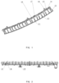
Fig. 1 is a schematic structural view of a collapsible rear bumper inner support provided by an embodiment of the present disclosure; -
Fig. 2 is a schematic front view of a collapsible rear bumper inner support provided by an embodiment of the present disclosure; -
Fig. 3 is a schematic rear view of a collapsible rear bumper inner support provided by the embodiment of the present disclosure; -
Fig. 4 is a schematic left view of a collapsible rear bumper inner support provided by the embodiment of the present disclosure; -
Fig. 5 is a schematic assembled view of a collapsible rear bumper inner support provided by the embodiment of the present disclosure; -
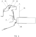
Fig. 6 is a schematic cross-sectional assembly view of a collapsible rear bumper inner support provided by the embodiment of the present disclosure; - Wherein, the reference numerals in the figure correspond to: 11-Support rear face, 12-Collapse rib, 13-Support side face, 14-Support front face, 15-Upper installation structure, 16-Positioning pin, 17-Upper clamping structure, 18-Lower clamping structure, 19-Lower installation structure, 2-Rear wall metal panel, 3-Rear bumper mask, 4-Rear anti-collision beam, 51-Lower portion of the collision device, 52-Lower portion of the collision device.
- In order to make the purpose, the technical solutions and the advantages of the present disclosure more clearly, the present disclosure will be further described in detail in combination with the embodiments. Obviously, the described embodiments are only some of the embodiments of the present disclosure, rather than all of them. Based on the embodiments of the present disclosure, all other embodiments obtained by those of ordinary skill in the art without creative work will fall within the protection scope of the present disclosure.
- It should be noted that in the description of the present disclosure, terms such as "first" and "second" are used to distinguish similar objects, and are not necessarily used to describe a specific order or sequence. It is to be understood that the data so used are interchangeable under appropriate circumstances such that the embodiments of the present disclosure described herein can be practiced in sequences other than those illustrated or described herein.
- In the present disclosure, the orientation or positional relationship indicated by the terms "upper", "lower", "top", "bottom", etc. are based on the orientation or positional relationship shown in the drawings, and are only for the convenience of describing the present disclosure and simplifying the description , rather than indicating or implying that the device or element must have a specific orientation, be constructed and operate in a specific orientation, and thus should not be construed as limitation of the disclosure. The X direction refers to the length direction of the vehicle, the Y direction refers to the width direction of the vehicle, and the Z direction refers to the height direction of the vehicle.
- In addition, unless be clearly specified and limited, terms such as "install", "connect", "link" and "fix" in the present disclosure should be interpreted in a broad sense, for example, it can be a fixed connection or a detachable connection , or integrated into a single piece; it may be directly connected, or indirectly connected through an intermediary, and may be an internal communication between two elements or an interaction relationship between two elements, unless otherwise clearly defined. For those of ordinary skill in the art the specific meanings of the above terms in the present disclosure can be understood according to specific situations.
- For the problem that the rear bumper inner support cannot absorb the impact energy effectively due to the impact energy generated during the rear collision of the vehicle is large, there are two common solutions at present. One solution is to raise the split position of the tailgate, ensure that the rear bumper inner support is located above the collision device, and will not contact with the collision device during the collision, but this solution will cause the tail sill of the luggage compartment to be too high, and the tail sill is about 800mm from the ground, which is inconvenient to take and place items, causes user complaints, and has a great impact on the modeling style. Another solution is to reserve enough space in X direction between the rear wall sheet metal and the rear bumper mask to ensure that the rear bumper inner support will not interfere with the collision device in case of rear collision. However, this solution will occupy the luggage compartment space and reduce the space utilization rate of the vehicle.
- In view of the above defects, this embodiment provides a collapsible rear bumper inner support. Referring to
Figs. 1-6 , the collapsible rear bumper inner support of this embodiment includes a supportrear face 11, asupport front face 14, a plurality ofcollapse ribs 12, and a pair of support side faces 13. The supportrear face 11 is opposite to thesupport front face 14, and the pair of support side faces 13 are symmetrically arranged between the supportrear face 11 and thesupport front face 14. A first end of the support side face 13 is connected with the supportrear face 11, a second end of the support side face 13 is connected with thesupport front face 14. The supportrear face 11, the support side faces 13 and thesupport front face 14 form a truss. Thecollapse ribs 12 are arranged between the pair of support side faces 13. A first end of thecollapse rib 12 is connected with the supportrear face 11, and a second end of thecollapse rib 12 is connected with thesupport front face 14, and the rear bumper inner support is symmetrical in Y direction. The supportrear face 11 can transmit the impact force to thecollapse ribs 12, and thecollapse ribs 12 can deform and collapse. - The collapsible rear bumper inner support in this embodiment could in front contact with the collision device, and absorbs energy through the deformation and collapse of the
collapse ribs 12. According to the collapsible rear bumper inner support in this embodiment, during the front collision test of the rear bumper at 10km/h, thecollapse ribs 12 can quickly collapse and crush, absorb the impact energy, fall off from the rear bumper inner support, release space and absorb the impact energy, have high collapse efficiency, and prevent the impact energy from being transmitted to thesupport front face 14, thereby protecting the rearwall metal panel 2 of the vehicle body from deformation. Compared with the prior art, the rear bumper inner support in this embodiment has no special requirements on the height of the tailgate split, and does not need to leave space between the rearwall metal panel 2 and therear bumper mask 3 as well. The collapsible rear bumper inner support in the embodiment of the present disclosure does not affect the modeling style, and at the same time, on the premise of ensuring the convenience of taking and placing items in the luggage compartment and the utilization rate of the rear space of the vehicle will not be affected, the problem of deformation and damage of the rear wall sheet metal caused by the rear bumper inner support can not be collapsed effectively during the front impact test of the rear bumper of the vehicle at 10km/h can be solved, which can meet the requirements of modeling intention, the increase of the luggage compartment space, and the convenience of taking and placing luggage articles at the same time. - As a specific embodiment, the support
rear face 11, the support side faces 13 and thesupport front face 14 form a rectangular truss, so as to uniformly distribute the impact energy and symmetrically transfer it to the front of the rear bumper inner support, so that thecollapse ribs 12 can effectively and fully deform and collapse. - It should be noted that, in some other embodiments, the support
rear face 11, the support side faces 13 and thesupport front face 14 can also form trusses of other shapes, and are not limited to the above-mentioned rectangular trusses, as long as they can realize the same functions as those in the embodiments of the present disclosure. - As a specific embodiment, the
collapse rib 12 has a first force-bearing area and a second force-bearing area. When the rear bumper inner support is impacted, the force exerted on the first force-bearing area is greater than that on the second force-bearing area, so that it can deform and collapse quickly. There may be one or more first force-bearing areas. - As a specific embodiment, the
collapse rib 12 has a V-shaped structure, and tips at bend portions of the V-shaped structures face toward an end of the rear bumper inner support along the length direction. Specifically, for thecollapse ribs 12 located at the left portion of the rear bumper inner support, the tips of the bending portions face to the left end of the rear bumper inner support, and for thecollapse ribs 12 located on the right portion of the rear bumper inner support, the tips of the bending portions face to the right end of the rear bumper inner support; or, for thecollapse rib 12 located at the left portion of the rear bumper inner support, the tips of the bending portions face to the right end of the rear bumper inner support, and for thecollapse rib 12 located at the right portion of the rear bumper inner support, the tips of the bending portions face to the left end of the rear bumper inner support. The tip of the bending portion of the V-shaped structure is the first force-bearing area, and other areas outside the bending portions are the second force-bearing area. When subjected to an impact force, the bending portion is the first portion to deform and fragment, and the "V" shape also play a guide role. Preferably, thecollapse ribs 12 can be evenly distributed along the length direction of the rear bumper inner support, so as to evenly distribute the impact force. During the front collision test of the rear bumper inner support at 10km/h, thecollapse rib 12 rapidly deforms at the tip of the V-shaped structure, collapses, and shatters to absorb the impact energy, thus protecting the rearwall metal panel 2 of the vehicle body from deformation. In this embodiment, the structure of the rear bumper inner support is optimized, and using symmetrical V-shaped collapse rib. At the same time, the X-direction dimension of the mounting surface can be minimized through the structure optimization, thereby ensuring the convenience of taking and placing items from the luggage compartment and the utilization rate of the rear space of the vehicle are not affected, which can meet the requirements of styling intention, improving luggage compartment space and the convenience of taking and placing items at the same time. - Those having ordinary skill in the art can understand that, in some other embodiments, the structure and arrangement of the
collapse ribs 12 can be appropriately changed according to actual needs, as long as they can realize the same functions as those in the embodiments of the present disclosure. - As a specific embodiment, the material of the
collapse rib 12 can be a reinforced composite material, so that it has better buffering and energy-absorbing effects during a collision. As a non-limiting example, thecollapse rib 12 may be made of polypropylene plastic (PP-GF30) containing 30% glass fibers, or polycarbonate and acrylonitrile-butadiene-styrene copolymer and mixture (PC/ABS), or polyethylene glycol and propylene oxide copolymer (PEP). - On the premise of ensuring the convenience of taking and placing items in the luggage compartment and the utilization rate of the rear space of the vehicle, the rear bumper inner support in this embodiment absorbs the impact energy through the rapid collapse and fragmentation of the
collapse rib 12, and protects the rearwall metal panel 2 of the vehicle body from deformation. Moreover, compared with the rear bumper inner support in the prior art, the rear bumper inner support in this embodiment is lighter in weight and lower in cost. - As a specific embodiment, continue to refer to
FIG. 1 , thesupport front face 14 is provided apositioning pin 16, and thepositioning pin 16 is used to position the rear bumper inner support on the rearwall metal panel 2 of the vehicle body. - As a specific embodiment, continue to refer to
Fig. 1 , thesupport front face 14 is provided a plurality ofupper installation structures 15, for connecting with the rear wall metal panel of the vehicle body. The structure of theupper installation structure 15 can be set according to actual needs. Theupper installation structure 15 is provided with a first installation hole, and bolts welded on the rearwall metal panel 2 of the vehicle body pass through the first installation holes and are fixedly connected by fasteners. Specifically, the fasteners may be flange nuts, and those of ordinary skill in the art may use other fasteners to realize the connection between thesupport front face 14 and the rearwall metal panel 2 of the vehicle body according to requirements. - As a specific embodiment, the
support front face 14 is provided with a plurality oflower installation structures 19, for connecting with the rearwall metal panel 2 of the vehicle body. The structure of thelower installation structure 19 can be set according to actual needs. A horizontal plane where thelower installation structure 19 locates is lower than a horizontal plane where theupper installation structure 15 locates, and thelower installation structure 19 is provided with a second installation hole. Bolts welded on the rearwall metal panel 2 of the vehicle body pass through the second installation holes and are fixedly connected by fasteners. Specifically, the fasteners may be flange nuts, and those of ordinary skill in the art may use other fasteners to realize the connection between thesupport front face 14 and the rearwall metal panel 2 of the vehicle body according to requirements. - As a specific embodiment, the
upper installation structure 15 and thelower installation structure 19 are arranged alternately to ensure that the connection between thesupport front face 14 and the rearwall metal panel 2 of the vehicle body is stable and reliable. - As a specific embodiment, the
support front face 14 is provided with a plurality ofupper clamping structures 17 for connecting with therear bumper mask 3. Theupper clamping structure 17 is engaged with the back of therear bumper mask 3, specifically, the back of therear bumper mask 3 is provided with a groove structure matching with the upper engagingstructure 17, so that the upper engagingstructure 17 engages with the groove structure. - Specifically, the
upper clamping structure 17 may be a clamping tongue, and the clamping tongue engages with the groove structure. The clamping structure is simple, convenient to connect, and reliable to fix. Those of ordinary skill in the art can understand that, in some other embodiments, theupper engaging structure 17 can also be set as other structures, as long as they can realize the same function as that in the embodiment of the present disclosure. - As a specific embodiment, the
support front face 14 is provided with a plurality oflower clamping structure 18 for connecting with therear bumper mask 3, and a horizontal plane where thelower clamping structure 18 locates is lower than a horizontal plane where theupper clamping structure 17 locates. Thelower clamping structure 18 is engaged with the back of therear bumper mask 3. Specifically, the back of therear bumper mask 3 can be provided with a groove structure matching with thelower clamping structure 18, so that thelower clamping structure 18 engages with the groove structure. - Specifically, the
lower clamping structure 18 can be a clamping tongue, and the clamping tongue engages with the groove structure. The clamping structure is simple, convenient to connect, and reliable to fix. Those of ordinary skill in the art can understand that, in some other embodiments, the lower engagingstructure 18 can also be set as other structures, as long as the same they can realize the same function as that in the embodiment of the present disclosure. - As a specific embodiment, the
lower clamping structure 18 and theupper clamping structure 17 are arranged alternately, which can ensure that the connection between thesupport front face 14 and therear bumper mask 3 is stable and reliable. The assembly view of the collapsible rear bumper inner support is shown inFig. 5 andFig. 6 . - As a specific embodiment, it also includes a support member for supporting the rear bumper inner support. The specific structure of the support member can be set according to actual needs. A first end of the support member is connected to the support
rear face 11. A second end of the support member is connected to thesupport front face 14, the support member is close to thesupport side face 13, and can strengthen the structural strength of the rear bumper inner support. - The foregoing embodiments of the present disclosure have the following advantages:
- 1) During the front collision test of the rear bumper at 10km/h, the collapse ribs of the collapsible rear bumper inner support in the embodiment of the present disclosure can quickly collapse and crash, absorb the impact energy, fall off from the rear bumper inner support, release space and absorb impact energy, and have high collapse efficiency, thereby protecting the rear wall metal panel of the vehicle body from deformation.
- 2) The rear bumper inner support of the present disclosure makes front contact with the collision device, and absorbs energy through the rapid collapse of the collapse ribs. It has no special requirements for the height of the tailgate split, and does not require to leave a large space between the rear wall metal panel and the rear bumper mask. Compared with the prior art, it can improve the degree of freedom in the design of the vehicle, and simultaneously meet the requirements of the styling intention, improving luggage compartment space, and the convenience of picking and placing items.
- 3) Compared with the prior art, the rear bumper inner support in the embodiment of the present disclosure is lighter in weight and lower in cost.
- Another embodiment of the present disclosure provides a rear bumper, which includes the collapsible rear bumper inner support in the above embodiment.
- For the rear bumper in this embodiment, the process of collapsing and absorbing energy during the collision process includes: the
rear bumper mask 3 contacts thelower portion 52 of the collision device, therear bumper mask 3 deforms, and thelower portion 52 of the collision device contacts the rear anti-collision beam 4, the rear anti-collision beam 4 is deformed, the impact energy is attenuated, and thelower portion 51 of the collision device is in contact with the supportrear face 11 of the rear bumper inner support; the impact force is transmitted to thecollapse ribs 12 through the supportrear face 11, and the supportrear face 11 and thecollapse ribs 12 are quickly broken, and fall off from the rear bumper inner support to absorb the impact energy and form a safety gap between thelower portion 51 of the collision device and the frontsupport front face 14, to prevent the rearwall metal panel 2 and the front support front face 14 from contacting with thelower portion 51 of the collision device, while the rear anti-collision beam 4 continues to deform and absorb energy until the collision ends. Since the collapsible rear bumper inner support has the above-mentioned technical effects, the rear bumper with the collapsible rear bumper inner support should also have the same technical effect, and will not be repeated here. - Another embodiment of the present disclosure also provides a vehicle, which includes the rear bumper in the above embodiment. Since the above-mentioned rear bumper has the above-mentioned technical effects, the vehicle with the above-mentioned rear bumper should also have the same technical effect, and will not be repeated here.
- The above descriptions are only preferred embodiments of the present disclosure, and it should be pointed out that for those of ordinary skill in the art, without departing from the principle of the present disclosure, some improvements and modifications can also be made, and these improvements and modifications are also considered to be included in the protection scope of the present disclosure.
Claims (15)
- A collapsible rear bumper inner support, characterized in that comprising a bracket rear face (11), a bracket front face (14), a plurality of collapse ribs (12) and a pair of bracket side faces (13);the support rear face (11) being opposite to the support front face (14), and the pair of the support side faces (13) being symmetrically arranged between the support rear face (11) and the support front face (14), a first end of the support side face (13) being connected with the support rear face (11), a second end of the support side face (13) being connected with the support front face (14), and the support rear face (11), the support side faces (13) and the support front face (14) form a truss;the collapse rid (12) being arranged between the pair of support side faces (13), a first end of the collapse rid (12) being connected to the support rear face (11), and a second end of the collapse rid (12) being connected to the support front face (14), and the rear bumper inner support being symmetrical in the Y direction.
- The collapsible rear bumper inner support according to claim 1, wherein the collapse rib (12) has a V-shaped structure, and a tip of the V-shaped structure faces toward an end of the rear bumper inner support along a length direction.
- The collapsible rear bumper inner support according to claim 1, wherein the collapse ribs (12) are evenly distributed along a length direction of the rear bumper inner support.
- The collapsible rear bumper inner support according to claim 1, wherein the support rear face (11), the support side faces (13) and the support front face (14) form a rectangular truss.
- The collapsible rear bumper inner support according to claim 1, wherein the support front face (14) is provided a positioning pin (16) for positioning the rear bumper inner support on a rear wall sheet metal (2) of a vehicle body.
- The collapsible rear bumper inner support according to claim 1, wherein, the support front face (14) is provided with a plurality of upper installation structures (15) for connecting with a rear wall sheet metal (2) of a vehicle body, the upper installation structure (15) is provided with a first installation hole, and bolts welded on the rear wall sheet metal (2) pass through the first installation holes and are fixed by fasteners.
- The collapsible rear bumper inner support according to claim 6, wherein the support front face (14) is provided with a plurality of lower installation structures (19) for connecting with the rear wall sheet metal (2) of the vehicle body, a horizontal plane where the lower installation structure (19) locates is lower than a horizontal plane where the upper installation structure (15) locates, the lower installation structure (19) is provided a second installation hole, bolts welded on the rear wall sheet metal (2) of the vehicle body pass through the second installation holes and are fixed by fasteners.
- The collapsible rear bumper inner support according to claim 7, wherein the upper installation structures (15) and the lower installation structures (19) are arranged alternately.
- The collapsible rear bumper inner support according to claim 7, wherein the fastener is a flange nut.
- The collapsible rear bumper inner support according to claim 1, wherein the support front face (14) is provided with a plurality upper clamping structures (17) for connecting with a rear bumper mask (3), the upper clamping structure (17) is engaged with a back of the rear bumper mask (3).
- The collapsible rear bumper inner support according to claim 10, wherein the support front face (14) is provided with a plurality of lower clamping structures (18) for connecting with the rear bumper mask (3), a horizontal plane where the lower clamping structure (18) locates is lower than a horizontal plane where the upper clamping structure (17) locates, and the lower clamping structure (18) is engaged with the back of the rear bumper mask (3).
- The collapsible rear bumper inner support according to claim 11, wherein the lower clamping structures (18) and the upper clamping structures (17) are arranged alternately.
- The collapsible rear bumper inner support according to claim 1, further comprising a support member for supporting the rear bumper inner support, a first end of the support member is connected to the support rear face (11), a second end of the support member is connected with the support front face (14), and the support member is close to the support side face (13).
- A rear bumper, characterized in that comprising the collapsible rear bumper inner support according to any one of claims 1-13.
- A vehicle, characterized in that comprising the rear bumper according to claim 14.
Applications Claiming Priority (1)
| Application Number | Priority Date | Filing Date | Title |
|---|---|---|---|
| PCT/CN2020/101363 WO2022006861A1 (en) | 2020-07-10 | 2020-07-10 | Collapsible rear bumper inner support, rear bumper, and vehicle |
Publications (4)
| Publication Number | Publication Date |
|---|---|
| EP4180276A1 true EP4180276A1 (en) | 2023-05-17 |
| EP4180276A4 EP4180276A4 (en) | 2024-04-10 |
| EP4180276B1 EP4180276B1 (en) | 2025-08-13 |
| EP4180276C0 EP4180276C0 (en) | 2025-08-13 |
Family
ID=79552200
Family Applications (1)
| Application Number | Title | Priority Date | Filing Date |
|---|---|---|---|
| EP20943936.3A Active EP4180276B1 (en) | 2020-07-10 | 2020-07-10 | Collapsible rear bumper inner support, rear bumper, and vehicle |
Country Status (3)
| Country | Link |
|---|---|
| EP (1) | EP4180276B1 (en) |
| CN (1) | CN115835984A (en) |
| WO (1) | WO2022006861A1 (en) |
Family Cites Families (15)
| Publication number | Priority date | Publication date | Assignee | Title |
|---|---|---|---|---|
| DE102004048504A1 (en) * | 2004-10-05 | 2006-04-13 | Rehau Ag + Co | Bodywork element comprises an absorber body which serves for dissipation of impact energy and consists of a plurality of plastic buckling elements with support walls |
| JP2009280141A (en) * | 2008-05-23 | 2009-12-03 | Kobe Steel Ltd | Bumper stay and bumper structure |
| FR2966104B1 (en) * | 2010-10-15 | 2014-06-13 | Faurecia Bloc Avant | IMPROVED ENERGY ABSORBER, IN PARTICULAR FOR A BUMPER BEAM FOR A MOTOR VEHICLE |
| KR20120062217A (en) * | 2010-12-06 | 2012-06-14 | 현대자동차주식회사 | Crash Box of Car Bumper |
| CN103802772B (en) * | 2012-11-06 | 2017-05-17 | 标致雪铁龙(中国)汽车贸易有限公司 | Elastic installation device used for vehicle rear bumper middle support and installation method of elastic installation device used for vehicle rear bumper middle support |
| FR3003828B1 (en) * | 2013-03-27 | 2015-05-01 | Faurecia Bloc Avant | BUMPER FOR MOTOR VEHICLE |
| CN204567545U (en) * | 2015-05-05 | 2015-08-19 | 神龙汽车有限公司 | A kind of fixed sturcture of automobile rear bumper mounting bracket |
| CN204845823U (en) * | 2015-07-22 | 2015-12-09 | 北汽福田汽车股份有限公司 | A vehicle that is used for rear bumper subassembly of vehicle and has it |
| EP3135949B1 (en) * | 2015-08-27 | 2019-06-19 | Airbus Operations S.L. | Deformable structure for absorption of energy from mechanical and/or acoustic impacts |
| DE102015217465A1 (en) * | 2015-09-11 | 2017-03-16 | Volkswagen Aktiengesellschaft | Arrangement of a extending in the vehicle transverse direction guide member by means of at least one holder on a bumper cross member of a motor vehicle |
| US9827933B1 (en) * | 2016-05-19 | 2017-11-28 | Ford Global Technologies, Llc | Energy absorber with fixed angled fins |
| US10046723B1 (en) * | 2017-03-14 | 2018-08-14 | Ford Global Technologies, Llc | Self-adaptive, energy-absorbing bumper |
| CN208021381U (en) * | 2017-09-21 | 2018-10-30 | 天津华夏联盛汽车部件有限公司 | A kind of automobile rear bumper left installation bracket assembly |
| CN110696765A (en) * | 2018-07-09 | 2020-01-17 | 标致雪铁龙汽车股份有限公司 | Support and vehicle in rear bumper of vehicle |
| WO2020086032A1 (en) * | 2018-10-24 | 2020-04-30 | Istanbul Teknik Universitesi | Automobile crash box system |
-
2020
- 2020-07-10 CN CN202080102582.8A patent/CN115835984A/en active Pending
- 2020-07-10 EP EP20943936.3A patent/EP4180276B1/en active Active
- 2020-07-10 WO PCT/CN2020/101363 patent/WO2022006861A1/en not_active Ceased
Also Published As
| Publication number | Publication date |
|---|---|
| EP4180276B1 (en) | 2025-08-13 |
| EP4180276A4 (en) | 2024-04-10 |
| EP4180276C0 (en) | 2025-08-13 |
| WO2022006861A1 (en) | 2022-01-13 |
| CN115835984A (en) | 2023-03-21 |
Similar Documents
| Publication | Publication Date | Title |
|---|---|---|
| CN211731294U (en) | Preceding crashproof roof beam assembly and have its vehicle | |
| CN103786671A (en) | Front body structure of vehicle | |
| EP4180276B1 (en) | Collapsible rear bumper inner support, rear bumper, and vehicle | |
| CN209366086U (en) | A kind of automobile front bumper and automobile | |
| CN214451336U (en) | A body rear wall structure and an automobile | |
| CN109878574A (en) | An automobile body structure for coping with 25% offset collision and its working method | |
| CN211765376U (en) | GMT rear anti-collision beam | |
| CN102923050B (en) | Protecting and energy-absorbing structure of rear fog lamp of automobile | |
| CN115352391B (en) | A collision sensor installation structure and vehicle | |
| CN101982365A (en) | Bias collision device and automobile with same | |
| CN218141405U (en) | Anticollision roof beam, anticollision roof beam assembly and vehicle | |
| CN115366994B (en) | A protection structure and vehicle for a front cabin area controller | |
| CN210337829U (en) | Automobile and front anti-collision beam assembly | |
| CN218021831U (en) | Longeron assembly and vehicle | |
| KR20120039335A (en) | Crash box | |
| CN217945119U (en) | Vehicle safety anti-collision beam based on infrared anti-collision detection technology | |
| CN206841523U (en) | The double longeron endergonic structures of major-minor formula | |
| CN205256248U (en) | Automobile energy -absorbing protection crashproof roof beam in back and automobile | |
| CN221213877U (en) | Anti-collision beam assembly and vehicle | |
| CN112590700A (en) | Integrated multi-stage buffer automobile lower guard plate device and protection method | |
| CN211364479U (en) | A body end reinforcement structure for offset collision | |
| CN220785685U (en) | Automobile collision energy-absorbing box | |
| CN219601176U (en) | Anti-collision beam assembly and vehicle | |
| CN211519659U (en) | Automobile side wall column collision battery protection reinforcing structure | |
| CN202896676U (en) | Automobile front longitudinal beam |
Legal Events
| Date | Code | Title | Description |
|---|---|---|---|
| STAA | Information on the status of an ep patent application or granted ep patent |
Free format text: STATUS: THE INTERNATIONAL PUBLICATION HAS BEEN MADE |
|
| PUAI | Public reference made under article 153(3) epc to a published international application that has entered the european phase |
Free format text: ORIGINAL CODE: 0009012 |
|
| STAA | Information on the status of an ep patent application or granted ep patent |
Free format text: STATUS: REQUEST FOR EXAMINATION WAS MADE |
|
| 17P | Request for examination filed |
Effective date: 20230206 |
|
| AK | Designated contracting states |
Kind code of ref document: A1 Designated state(s): AL AT BE BG CH CY CZ DE DK EE ES FI FR GB GR HR HU IE IS IT LI LT LU LV MC MK MT NL NO PL PT RO RS SE SI SK SM TR |
|
| DAV | Request for validation of the european patent (deleted) | ||
| DAX | Request for extension of the european patent (deleted) | ||
| A4 | Supplementary search report drawn up and despatched |
Effective date: 20240314 |
|
| RIC1 | Information provided on ipc code assigned before grant |
Ipc: B60R 19/34 20060101AFI20240307BHEP |
|
| RAP1 | Party data changed (applicant data changed or rights of an application transferred) |
Owner name: ZHEJIANG GEELY HOLDING GROUP CO., LTD. Owner name: ZHEJIANG ZEEKR INTELLIGENT TECHNOLOGY CO., LTD |
|
| GRAP | Despatch of communication of intention to grant a patent |
Free format text: ORIGINAL CODE: EPIDOSNIGR1 |
|
| STAA | Information on the status of an ep patent application or granted ep patent |
Free format text: STATUS: GRANT OF PATENT IS INTENDED |
|
| GRAS | Grant fee paid |
Free format text: ORIGINAL CODE: EPIDOSNIGR3 |
|
| INTG | Intention to grant announced |
Effective date: 20250506 |
|
| GRAA | (expected) grant |
Free format text: ORIGINAL CODE: 0009210 |
|
| STAA | Information on the status of an ep patent application or granted ep patent |
Free format text: STATUS: THE PATENT HAS BEEN GRANTED |
|
| AK | Designated contracting states |
Kind code of ref document: B1 Designated state(s): AL AT BE BG CH CY CZ DE DK EE ES FI FR GB GR HR HU IE IS IT LI LT LU LV MC MK MT NL NO PL PT RO RS SE SI SK SM TR |
|
| REG | Reference to a national code |
Ref country code: GB Ref legal event code: FG4D |
|
| REG | Reference to a national code |
Ref country code: CH Ref legal event code: EP |
|
| REG | Reference to a national code |
Ref country code: DE Ref legal event code: R096 Ref document number: 602020056772 Country of ref document: DE |
|
| REG | Reference to a national code |
Ref country code: IE Ref legal event code: FG4D |
|
| U01 | Request for unitary effect filed |
Effective date: 20250827 |
|
| U07 | Unitary effect registered |
Designated state(s): AT BE BG DE DK EE FI FR IT LT LU LV MT NL PT RO SE SI Effective date: 20250902 |
|
| PG25 | Lapsed in a contracting state [announced via postgrant information from national office to epo] |
Ref country code: IS Free format text: LAPSE BECAUSE OF FAILURE TO SUBMIT A TRANSLATION OF THE DESCRIPTION OR TO PAY THE FEE WITHIN THE PRESCRIBED TIME-LIMIT Effective date: 20251213 |
|
| PG25 | Lapsed in a contracting state [announced via postgrant information from national office to epo] |
Ref country code: NO Free format text: LAPSE BECAUSE OF FAILURE TO SUBMIT A TRANSLATION OF THE DESCRIPTION OR TO PAY THE FEE WITHIN THE PRESCRIBED TIME-LIMIT Effective date: 20251113 |
|
| PG25 | Lapsed in a contracting state [announced via postgrant information from national office to epo] |
Ref country code: HR Free format text: LAPSE BECAUSE OF FAILURE TO SUBMIT A TRANSLATION OF THE DESCRIPTION OR TO PAY THE FEE WITHIN THE PRESCRIBED TIME-LIMIT Effective date: 20250813 |
|
| PG25 | Lapsed in a contracting state [announced via postgrant information from national office to epo] |
Ref country code: GR Free format text: LAPSE BECAUSE OF FAILURE TO SUBMIT A TRANSLATION OF THE DESCRIPTION OR TO PAY THE FEE WITHIN THE PRESCRIBED TIME-LIMIT Effective date: 20251114 |
|
| PG25 | Lapsed in a contracting state [announced via postgrant information from national office to epo] |
Ref country code: PL Free format text: LAPSE BECAUSE OF FAILURE TO SUBMIT A TRANSLATION OF THE DESCRIPTION OR TO PAY THE FEE WITHIN THE PRESCRIBED TIME-LIMIT Effective date: 20250813 |
|
| PG25 | Lapsed in a contracting state [announced via postgrant information from national office to epo] |
Ref country code: RS Free format text: LAPSE BECAUSE OF FAILURE TO SUBMIT A TRANSLATION OF THE DESCRIPTION OR TO PAY THE FEE WITHIN THE PRESCRIBED TIME-LIMIT Effective date: 20251113 |
|
| PG25 | Lapsed in a contracting state [announced via postgrant information from national office to epo] |
Ref country code: ES Free format text: LAPSE BECAUSE OF FAILURE TO SUBMIT A TRANSLATION OF THE DESCRIPTION OR TO PAY THE FEE WITHIN THE PRESCRIBED TIME-LIMIT Effective date: 20250813 |
|
| PG25 | Lapsed in a contracting state [announced via postgrant information from national office to epo] |
Ref country code: SM Free format text: LAPSE BECAUSE OF FAILURE TO SUBMIT A TRANSLATION OF THE DESCRIPTION OR TO PAY THE FEE WITHIN THE PRESCRIBED TIME-LIMIT Effective date: 20250813 |
|
| PG25 | Lapsed in a contracting state [announced via postgrant information from national office to epo] |
Ref country code: CZ Free format text: LAPSE BECAUSE OF FAILURE TO SUBMIT A TRANSLATION OF THE DESCRIPTION OR TO PAY THE FEE WITHIN THE PRESCRIBED TIME-LIMIT Effective date: 20250813 |
|
| PG25 | Lapsed in a contracting state [announced via postgrant information from national office to epo] |
Ref country code: SK Free format text: LAPSE BECAUSE OF FAILURE TO SUBMIT A TRANSLATION OF THE DESCRIPTION OR TO PAY THE FEE WITHIN THE PRESCRIBED TIME-LIMIT Effective date: 20250813 |