EP4180244A1 - Tire - Google Patents
Tire Download PDFInfo
- Publication number
- EP4180244A1 EP4180244A1 EP22206274.7A EP22206274A EP4180244A1 EP 4180244 A1 EP4180244 A1 EP 4180244A1 EP 22206274 A EP22206274 A EP 22206274A EP 4180244 A1 EP4180244 A1 EP 4180244A1
- Authority
- EP
- European Patent Office
- Prior art keywords
- tire
- groove
- circumferential
- crown
- grooves
- Prior art date
- Legal status (The legal status is an assumption and is not a legal conclusion. Google has not performed a legal analysis and makes no representation as to the accuracy of the status listed.)
- Granted
Links
Images



Classifications
-
- B—PERFORMING OPERATIONS; TRANSPORTING
- B60—VEHICLES IN GENERAL
- B60C—VEHICLE TYRES; TYRE INFLATION; TYRE CHANGING; CONNECTING VALVES TO INFLATABLE ELASTIC BODIES IN GENERAL; DEVICES OR ARRANGEMENTS RELATED TO TYRES
- B60C11/00—Tyre tread bands; Tread patterns; Anti-skid inserts
- B60C11/03—Tread patterns
- B60C11/032—Patterns comprising isolated recesses
- B60C11/0323—Patterns comprising isolated recesses tread comprising channels under the tread surface, e.g. for draining water
-
- B—PERFORMING OPERATIONS; TRANSPORTING
- B60—VEHICLES IN GENERAL
- B60C—VEHICLE TYRES; TYRE INFLATION; TYRE CHANGING; CONNECTING VALVES TO INFLATABLE ELASTIC BODIES IN GENERAL; DEVICES OR ARRANGEMENTS RELATED TO TYRES
- B60C11/00—Tyre tread bands; Tread patterns; Anti-skid inserts
- B60C11/03—Tread patterns
- B60C11/0306—Patterns comprising block rows or discontinuous ribs
-
- B—PERFORMING OPERATIONS; TRANSPORTING
- B60—VEHICLES IN GENERAL
- B60C—VEHICLE TYRES; TYRE INFLATION; TYRE CHANGING; CONNECTING VALVES TO INFLATABLE ELASTIC BODIES IN GENERAL; DEVICES OR ARRANGEMENTS RELATED TO TYRES
- B60C11/00—Tyre tread bands; Tread patterns; Anti-skid inserts
- B60C11/03—Tread patterns
- B60C11/12—Tread patterns characterised by the use of narrow slits or incisions, e.g. sipes
- B60C11/1204—Tread patterns characterised by the use of narrow slits or incisions, e.g. sipes with special shape of the sipe
- B60C11/1218—Three-dimensional shape with regard to depth and extending direction
-
- B—PERFORMING OPERATIONS; TRANSPORTING
- B60—VEHICLES IN GENERAL
- B60C—VEHICLE TYRES; TYRE INFLATION; TYRE CHANGING; CONNECTING VALVES TO INFLATABLE ELASTIC BODIES IN GENERAL; DEVICES OR ARRANGEMENTS RELATED TO TYRES
- B60C11/00—Tyre tread bands; Tread patterns; Anti-skid inserts
- B60C11/03—Tread patterns
- B60C11/12—Tread patterns characterised by the use of narrow slits or incisions, e.g. sipes
- B60C11/1272—Width of the sipe
- B60C11/1281—Width of the sipe different within the same sipe, i.e. enlarged width portion at sipe bottom or along its length
-
- B—PERFORMING OPERATIONS; TRANSPORTING
- B60—VEHICLES IN GENERAL
- B60C—VEHICLE TYRES; TYRE INFLATION; TYRE CHANGING; CONNECTING VALVES TO INFLATABLE ELASTIC BODIES IN GENERAL; DEVICES OR ARRANGEMENTS RELATED TO TYRES
- B60C11/00—Tyre tread bands; Tread patterns; Anti-skid inserts
- B60C11/03—Tread patterns
- B60C2011/0337—Tread patterns characterised by particular design features of the pattern
- B60C2011/0339—Grooves
- B60C2011/0341—Circumferential grooves
- B60C2011/0346—Circumferential grooves with zigzag shape
-
- B—PERFORMING OPERATIONS; TRANSPORTING
- B60—VEHICLES IN GENERAL
- B60C—VEHICLE TYRES; TYRE INFLATION; TYRE CHANGING; CONNECTING VALVES TO INFLATABLE ELASTIC BODIES IN GENERAL; DEVICES OR ARRANGEMENTS RELATED TO TYRES
- B60C11/00—Tyre tread bands; Tread patterns; Anti-skid inserts
- B60C11/03—Tread patterns
- B60C2011/0337—Tread patterns characterised by particular design features of the pattern
- B60C2011/0339—Grooves
- B60C2011/0341—Circumferential grooves
- B60C2011/0348—Narrow grooves, i.e. having a width of less than 4 mm
-
- B—PERFORMING OPERATIONS; TRANSPORTING
- B60—VEHICLES IN GENERAL
- B60C—VEHICLE TYRES; TYRE INFLATION; TYRE CHANGING; CONNECTING VALVES TO INFLATABLE ELASTIC BODIES IN GENERAL; DEVICES OR ARRANGEMENTS RELATED TO TYRES
- B60C11/00—Tyre tread bands; Tread patterns; Anti-skid inserts
- B60C11/03—Tread patterns
- B60C2011/0337—Tread patterns characterised by particular design features of the pattern
- B60C2011/0339—Grooves
- B60C2011/0358—Lateral grooves, i.e. having an angle of 45 to 90 degees to the equatorial plane
-
- B—PERFORMING OPERATIONS; TRANSPORTING
- B60—VEHICLES IN GENERAL
- B60C—VEHICLE TYRES; TYRE INFLATION; TYRE CHANGING; CONNECTING VALVES TO INFLATABLE ELASTIC BODIES IN GENERAL; DEVICES OR ARRANGEMENTS RELATED TO TYRES
- B60C11/00—Tyre tread bands; Tread patterns; Anti-skid inserts
- B60C11/03—Tread patterns
- B60C11/12—Tread patterns characterised by the use of narrow slits or incisions, e.g. sipes
- B60C11/1204—Tread patterns characterised by the use of narrow slits or incisions, e.g. sipes with special shape of the sipe
- B60C2011/1213—Tread patterns characterised by the use of narrow slits or incisions, e.g. sipes with special shape of the sipe sinusoidal or zigzag at the tread surface
-
- B—PERFORMING OPERATIONS; TRANSPORTING
- B60—VEHICLES IN GENERAL
- B60C—VEHICLE TYRES; TYRE INFLATION; TYRE CHANGING; CONNECTING VALVES TO INFLATABLE ELASTIC BODIES IN GENERAL; DEVICES OR ARRANGEMENTS RELATED TO TYRES
- B60C2200/00—Tyres specially adapted for particular applications
- B60C2200/06—Tyres specially adapted for particular applications for heavy duty vehicles
-
- Y—GENERAL TAGGING OF NEW TECHNOLOGICAL DEVELOPMENTS; GENERAL TAGGING OF CROSS-SECTIONAL TECHNOLOGIES SPANNING OVER SEVERAL SECTIONS OF THE IPC; TECHNICAL SUBJECTS COVERED BY FORMER USPC CROSS-REFERENCE ART COLLECTIONS [XRACs] AND DIGESTS
- Y02—TECHNOLOGIES OR APPLICATIONS FOR MITIGATION OR ADAPTATION AGAINST CLIMATE CHANGE
- Y02T—CLIMATE CHANGE MITIGATION TECHNOLOGIES RELATED TO TRANSPORTATION
- Y02T10/00—Road transport of goods or passengers
- Y02T10/80—Technologies aiming to reduce greenhouse gasses emissions common to all road transportation technologies
- Y02T10/86—Optimisation of rolling resistance, e.g. weight reduction
Definitions
- the present disclosure relates to a tire.
- Japanese Laid-Open Patent Publication No. 2019-104411 describes a tire having, in a tread portion thereof, hexagonal blocks that are formed by a plurality of zigzag circumferential grooves and lateral grooves connecting the zigzag circumferential grooves.
- the zigzag circumferential grooves include a pair of center circumferential grooves, and a pair of shoulder circumferential grooves each having a larger groove width than the center circumferential grooves.
- the hexagonal blocks each have a second sipe that extends across the hexagonal block in the tire axial direction.
- Such a tire has a reduced rolling resistance, and the occurrence of cracks is suppressed in the groove bottoms of the lateral grooves.
- each center circumferential groove has a small groove width, which deteriorates drainage performance and therefore reduces wet performance.
- the present disclosure has been made in view of the above circumstances, and it is a main object of the present disclosure to provide a tire having improved wet performance while maintaining rolling resistance performance.
- the present disclosure is directed to a tire including a tread portion, wherein the tread portion includes a plurality of circumferential grooves extending in a zigzag manner in a tire circumferential direction so as to form zigzag peak portions, a plurality of lateral grooves connecting the zigzag peak portions of the circumferential grooves adjacent to each other in a tire axial direction, and a plurality of hexagonal blocks formed by the plurality of circumferential grooves and the plurality of lateral grooves, the circumferential grooves include a pair of shoulder circumferential grooves disposed closer to tread ends and at least one crown circumferential groove disposed inward in the tire axial direction of the pair of shoulder circumferential grooves, a groove width of the crown circumferential groove is smaller than groove widths of the pair of shoulder circumferential grooves, and each of the hexagonal blocks is provided with a sipe extending in the tire axial direction, and a wide groove portion connected to an inner side in a tire radial direction of the sipe and
- the tire of the present disclosure which has the above features, can have improved wet performance while maintaining rolling resistance performance.
- FIG. 1 is a plan view of a tread portion 2 of a tire 1 of the present disclosure.
- the tire 1 of the present disclosure is, for example, a heavy-duty pneumatic tire.
- the tire 1 of the present disclosure may, for example, be used as a pneumatic tire for a passenger car or motorcycle, or a non-pneumatic tire the interior of which is not filled with compressed air.
- the tread portion 2 includes a plurality of circumferential grooves 3 which extend in a zigzag manner in the tire circumferential direction so as to form zigzag peak portions K, and a plurality of lateral grooves 4 which connect the zigzag peak portions K of the circumferential grooves 3 adjacent to each other in the tire axial direction.
- the tread portion 2 includes, for example, a plurality of hexagonal blocks 5 formed by the circumferential grooves 3 and the lateral grooves 4.
- the circumferential grooves 3 include a pair of shoulder circumferential grooves 3A disposed closer to tread ends Te, and at least one crown circumferential groove 3B disposed inward in the tire axial direction of the pair of shoulder circumferential grooves 3A.
- a pair of crown circumferential grooves 3B are provided on both sides of a tire equator C, respectively.
- tread ends Te correspond to the outermost ground contact positions in the tire axial direction when the tire 1 is brought into contact with a flat surface at a camber angle of 0° with a normal load applied to the tire 1 in a normal state where the tire 1 is fitted on a normal rim and inflated to a normal internal pressure and no load is applied to the tire 1. Unless otherwise specified, the values of dimensions and the like of components of the tire 1 are measured in the normal state.
- the distance in the tire axial direction between both tread ends Te is a tread width TW.
- the "normal rim” is a rim that is defined, in a standard system including a standard on which the tire 1 is based, by the standard for each tire, and is, for example, the "standard rim” in the JATMA standard, the "Design Rim” in the TRA standard, or the “Measuring Rim” in the ETRTO standard.
- the "normal internal pressure” is an air pressure that is defined, in a standard system including a standard on which the tire 1 is based, by the standard for each tire, and is the “maximum air pressure” in the JATMA standard, the maximum value indicated in the table "TIRE LOAD LIMITS AT VARIOUS COLD INFLATION PRESSURES" in the TRA standard, or the “INFLATION PRESSURE” in the ETRTO standard.
- the "normal load” is a load that is defined, in a standard system including a standard on which the tire 1 is based, by the standard for each tire, and is the "maximum load capacity" in the JATMA standard, the maximum value indicated in the table "TIRE LOAD LIMITS AT VARIOUS COLD INFLATION PRESSURES" in the TRA standard, or the "LOAD CAPACITY" in the ETRTO standard.
- a groove width W2 of each crown circumferential groove 3B is smaller than a groove width W1 of each shoulder circumferential groove 3A. Due to this, the apparent stiffness of the hexagonal blocks 5 adjacent to the crown circumferential groove 3B, on which a great ground-contact pressure acts, is maintained at a high level, which suppresses a decrease in rolling resistance performance and wear resistance performance.
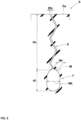
- FIG. 2 is a cross-sectional view taken along a line A-A in FIG. 1 .
- each hexagonal block 5 is provided with a sipe 6 extending in the tire axial direction, and a wide groove portion 7 which is connected to the inner side in the tire radial direction of the sipe 6 and extends in the tire axial direction with a width Wt larger than that of the sipe 6.
- the sipe 6 reduces the strain caused by the movement of the entire block, and therefore, rolling resistance performance and wear resistance performance are maintained at a higher level.
- the wide groove portion 7 can take in a layer of water on a tread surface of the block through the sipe 6, and drain the water from the circumferential groove 3 to the outside of the tread.
- the tire 1 of the present disclosure can have improved wet performance while maintaining rolling resistance performance.
- the term "sipe” refers to a slit-like recess having a width Ws of less than 1.5 mm in a direction perpendicular to the longitudinal direction thereof. Slit-like recesses are distinguished from grooves having a width of not less than 1.5 mm.
- the circumferential grooves 3 continuously extend in the tire circumferential direction.
- Each circumferential groove 3 includes first portions 3s continuously inclined toward one side with respect to the tire circumferential direction, and second portions 3t continuously inclined in a direction opposite to that of the first portions 3s.
- the first portions 3s and the second portions 3t are formed so as to be alternately arranged.
- the peak portion K is formed at an intersection of the first portion 3s and the second portion 3t.
- the peak portions K include first peak portions K1 which are convex toward the tire equator C, and second peak portions K2 which are convex toward the tread end Te.
- the first peak portions K1 and the second peak portions K2 are alternately arranged.
- angles ⁇ 1 of the first portions 3s and the second portions 3t with respect to the tire circumferential direction are each preferably not less than 5 degrees, more preferably not less than 10 degrees, and preferably not greater than 30 degrees, more preferably not greater than 25 degrees.
- the first portions 3s and the second portions 3t extend in a straight manner, for example.
- the first portions 3s and the second portions 3t are not limited to such a mode, and may extend in, for example, an arc.
- each circumferential groove 3 may extend in a wavy manner.
- Each crown circumferential groove 3B has a pair of groove walls 10e which extend in the longitudinal direction thereof.
- Each shoulder circumferential groove 3A also has a pair of groove walls 10i which extend in the longitudinal direction thereof. The pair of groove walls 10e are at least partially brought into contact with each other when the normal load is applied. The pair of groove walls 10i are not brought into contact each other when the normal load is applied.
- Such a crown circumferential groove 3B has high apparent stiffness due to the contact, and therefore, has excellent rolling resistance performance.
- the shoulder circumferential groove 3A improves wet performance.
- the groove width W2 of each crown circumferential groove 3B is preferably not less than 1% and more preferably not less than 5%, and is preferably not greater than 20% and more preferably not greater than 15%, of the groove width W1 of each shoulder circumferential groove 3A.
- the groove width W2 of each crown circumferential groove 3B is also preferably not less than 1.5 mm, and is preferably not greater than 3.0 mm and more preferably not greater than 2.5 mm.
- the groove width W1 of each shoulder circumferential groove 3A is not particularly limited, and is preferably 6.0 to 16.0 mm.
- the lateral grooves 4 include, for example, middle lateral grooves 4A, crown lateral grooves 4B, and shoulder lateral grooves 4C.
- Each middle lateral groove 4A connects, for example, the shoulder circumferential groove 3A and the crown circumferential groove 3B.
- the middle lateral groove 4A connects the peak portion K of the shoulder circumferential groove 3A and the peak portion K of the crown circumferential groove 3B.
- Each crown lateral groove 4B connects, for example, the pair of crown circumferential grooves 3B.
- the crown lateral groove 4B connects the peak portions K of the crown circumferential grooves 3B.
- Each shoulder lateral groove 4C connects, for example, the shoulder circumferential groove 3A and the tread end Te.
- the shoulder lateral groove 4C connects the peak portion K of the shoulder circumferential groove 3A and the tread end Te.
- each lateral groove 4 extends in a straight manner.
- the lateral groove 4 may extend in an arc, wavy, or zigzag manner.
- Each lateral groove 4 is inclined with respect to the tire axial direction.
- An angle ⁇ 2 of each lateral groove 4 with respect to the tire axial direction is preferably not less than 5 degrees and more preferably not less than 10 degrees, and is preferably not greater than 25 degrees and more preferably not greater than 20 degrees.
- the middle lateral grooves 4A, the crown lateral grooves 4B, and the shoulder lateral grooves 4C have the same angle ⁇ 2.
- the term "same angle" means that the difference in angle between the lateral grooves 4 is 0 degrees, and also encompasses an embodiment in which the absolute value of the difference in angle is not greater than 5 degrees.
- a groove width W3 of each lateral groove 4 is, for example, larger than the groove width W2 of each crown circumferential groove 3B.
- the groove width W3 of each lateral groove 4 is smaller than the groove width W1 of each shoulder circumferential groove 3A.
- the middle lateral grooves 4A, the crown lateral grooves 4B, and the shoulder lateral grooves 4C have the same groove width W3.
- the term "same groove width" means that the difference in groove width between the lateral grooves 4 is 0 (zero), and also encompasses an embodiment that the difference in groove width between the lateral grooves 4 is not greater than 2 mm.
- FIG. 3 is a plan view of the tread portion 2.
- the tread portion 2 of the present embodiment includes a plurality of middle blocks 8A, a plurality of crown blocks 8B, and a plurality of shoulder blocks 8C.
- Each middle block 8A is delimited by the shoulder circumferential groove 3A, the crown circumferential groove 3B, and the middle lateral grooves 4A adjacent to each other in the tire circumferential direction.
- the crown block 8B is delimited by the pair of crown circumferential grooves 3B, and the crown lateral grooves 4B adjacent to each other in the tire circumferential direction.
- Each shoulder block 8C is delimited by the tread end Te, the shoulder circumferential groove 3A, and the shoulder lateral grooves 4C adjacent to each other in the tire circumferential direction.
- the middle blocks 8A and the crown blocks 8B are formed as the hexagonal blocks 5.
- each middle block 8A of the present embodiment is provided with the sipe 6 and the wide groove portion 7.
- each crown block 8B is provided with the sipe 6 and the wide groove portion 7.
- each hexagonal block 5 refers to a barrel-shaped block that has a length LA in the tire axial direction which continuously increases from both ends in the tire circumferential direction of the block toward the center thereof and that expands toward both sides in the tire axial direction.
- Such a hexagonal block 5 has high stiffness in the tire axial direction, and therefore, has high wear resistance performance.
- the ratio (La/Wa) of a length La in the tire circumferential direction to a width Wa in the tire axial direction of the hexagonal block 5 is preferably not less than 1.2 and more preferably not less than 1.3, and is preferably not greater than 1.8 and more preferably not greater than 1.7.
- the length La and the width Wa are each a greatest value of the hexagonal block 5.
- both ends of each of the sipes 6 and the wide groove portions 7 are connected to the circumferential grooves 3. This further enhances wet performance.
- both ends of each of the sipes 6 and the wide groove portions 7 are connected to the peak portions K.
- each sipe 6 extends, for example, in a zigzag manner in the sipe longitudinal direction and the tire radial direction.
- the walls of the sipe 6 are brought into contact with each other and support each other, which increases apparent block stiffness, and therefore, improves rolling resistance performance and wear resistance performance.
- This type of sipe 6 is called a Miura fold (three-dimensional) sipe, for example.
- the sipe 6 is not limited to such a mode, and may, for example, extend in a straight manner in one of or both the sipe longitudinal direction and the tire radial direction.
- Each wide groove portion 7 has a circular or elliptical transverse cross-sectional shape. Such a wide groove portion 7 reduces strain in a bottom portion of the sipe and suppresses the occurrence of cracks or the like.
- the wide groove portion 7 extends in a straight manner in the longitudinal direction thereof. Such a wide groove portion has low drain resistance thereinside, and therefore, enhances wet performance.
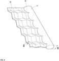
- FIG. 4 is a perspective view of the sipe 6 and the wide groove portion 7.
- a connection portion 9 at which the sipe 6 and the wide groove portion 7 are connected is shaped to extend in a zigzag manner in the longitudinal direction of the wide groove portion 7.
- Such a connection portion 9 serves to maintain the stiffness of the hexagonal block 5 at a higher level.
- the width (greatest width) Wt of the wide groove portion 7 is not particularly limited, and is preferably not less than 7 times and more preferably not less than 8 times, and is preferably not greater than 13 times and more preferably not greater than 12 times, the width (a width on a tread surface 5a of the hexagonal block 5) Ws of the sipe 6.
- a depth dt of the wide groove portion 7 is smaller than a depth ds of the sipe 6. Due to this, the block stiffness of the hexagonal block 5 is maintained at a high level.
- the depth dt of the wide groove portion 7 is preferably not less than 10%, more preferably not less than 20%, and even more preferably not less than 25%, and is preferably not greater than 50%, more preferably not greater than 40%, and even more preferably not greater than 35%, of the depth ds of the sipe 6. This improves rolling resistance performance and wet performance in a well-balanced manner.
- the sipe 6 and the wide groove portion 7 are partitioned at an outermost end M in the tire radial direction which has a width of 1.5 mm.
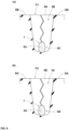
- FIG. 5(a) is a cross-sectional view taken along a line B-B in FIG. 3 .
- FIG. 5(b) is a cross-sectional view taken along a line C-C in FIG. 3 .
- FIG. 5(a) indicates a transverse cross-sectional area S2 of the crown lateral groove 4B.
- FIG. 5(b) indicates a transverse cross-sectional area S1 of the wide groove portion 7 of the middle block 8A.
- the transverse cross-sectional area S1 of the wide groove portion 7 of the middle block 8A is preferably not less than 10% and more preferably not less than 20%, and is preferably not greater than 40% and more preferably not greater than 30%, of the transverse cross-sectional area S2 of the crown lateral groove 4B.
- the transverse cross-sectional area S1 of the wide groove portion 7 of the middle block 8A is not less than 10% of the transverse cross-sectional area S2 of the crown lateral groove 4B, the wide groove portion 7 smoothly drains water. Since the transverse cross-sectional area S1 of the wide groove portion 7 of the middle block 8A is not greater than 40% of the transverse cross-sectional area S2 of the crown lateral groove 4B, the stiffness of the middle block 8A is maintained at a high level.
- the transverse cross-sectional area of the wide groove portion 7 of the crown block 8B is preferably not less than 10% and more preferably not less than 20%, and is preferably not greater than 40%, more preferably not greater than 30%, of the transverse cross-sectional area of the middle lateral groove 4A (not shown).
- FIG. 6(a) is a cross-sectional view taken along a line D-D in FIG. 3 .
- FIG. 6(a) shows the middle block 8A as viewed from the crown lateral groove 4B in a direction parallel to the tire axial direction.
- an inner end 7i in the tire axial direction of the wide groove portion 7 of the middle block 8A overlaps an intersection portion P1 of the crown lateral groove 4B and the crown circumferential groove 3B in the tire circumferential direction. This allows water in the crown lateral groove 4B to drain out of the tread portion 2 through the crown circumferential groove 3B or the wide groove portion 7 of the middle block 8A, which improves wet performance.
- a transverse cross-sectional area S3 of an overlap portion Q1 where the wide groove portion 7 of the middle block 8A and the intersection portion P1 overlap in tire circumferential direction is indicated by hatching.
- FIG. 6(b) is a cross-sectional view taken along a line E-E in FIG. 3 .
- FIG. 6(b) shows the crown block 8B as viewed from the middle lateral groove 4A in a direction parallel to the tire axial direction.
- both ends 7j in the tire axial direction of the wide groove portion 7 of the crown block 8B each overlap an intersection portion P3 of the middle lateral groove 4A and the crown circumferential groove 3B in the tire circumferential direction. This allows water in the wide groove portion 7 of the crown block 8B to smoothly flow into the crown circumferential groove 3B or the middle lateral groove 4A, which improves wet performance.
- FIG. 6(b) indicates a transverse cross-sectional area S6 of an overlap portion Q3 where the wide groove portion 7 of the crown block 8B and the intersection portion P3 overlap in the tire circumferential direction.
- the shoulder lateral grooves 4C and the shoulder blocks 8C each have, for example, a known configuration. Therefore, the shoulder lateral grooves 4C and the shoulder blocks 8C will not be described in detail.
- Heavy-duty tires (315/70R22.5) having the basic pattern shown in FIG. 1 were produced as test samples according to the specifications described in Table 1. Each test tire was tested for rolling resistance performance, wet performance, and wear resistance performance. The common specifications and the test methods are as follows.
- the rolling resistance of each test tire was measured using a rolling resistance testing machine in accordance with ISO 28580 under the following conditions. The results were indicated by indexes with the reciprocal of the value of Example 1 being regarded as 100. The higher the value is, the better the rolling resistance performance is.
- wet performance was tested in accordance with R117-02 (ECE Regulation, No. 117, Revision 2) using a test vehicle described below.
- wet performance a braking distance that the test vehicle traveled on a wet road surface from the start of braking at a predetermined initial speed until the test vehicle stopped was measured.
- indexes with the reciprocal of the braking distance of Example 1 being regarded as 100. The higher the value is, the better the wet performance is.
- the results of the tests demonstrated that the tires of the examples have excellent wet performance.
- the results of the tests also demonstrated that the rolling resistance performance and wear resistance performance of the tires of the examples are maintained at a high level.
- the present disclosure includes the following aspects.
- a tire including a tread portion, wherein
- transverse cross-sectional area of the wide groove portion of each middle block is 10% to 40% of a transverse cross-sectional area of the crown lateral groove.
Landscapes
- Engineering & Computer Science (AREA)
- Mechanical Engineering (AREA)
- Tires In General (AREA)
Abstract
Description
- The present disclosure relates to a tire.
-
Japanese Laid-Open Patent Publication No. 2019-104411 - However, the tire of
Japanese Laid-Open Patent Publication No. 2019-104411 - The present disclosure has been made in view of the above circumstances, and it is a main object of the present disclosure to provide a tire having improved wet performance while maintaining rolling resistance performance.
- The present disclosure is directed to a tire including a tread portion, wherein the tread portion includes a plurality of circumferential grooves extending in a zigzag manner in a tire circumferential direction so as to form zigzag peak portions, a plurality of lateral grooves connecting the zigzag peak portions of the circumferential grooves adjacent to each other in a tire axial direction, and a plurality of hexagonal blocks formed by the plurality of circumferential grooves and the plurality of lateral grooves, the circumferential grooves include a pair of shoulder circumferential grooves disposed closer to tread ends and at least one crown circumferential groove disposed inward in the tire axial direction of the pair of shoulder circumferential grooves, a groove width of the crown circumferential groove is smaller than groove widths of the pair of shoulder circumferential grooves, and each of the hexagonal blocks is provided with a sipe extending in the tire axial direction, and a wide groove portion connected to an inner side in a tire radial direction of the sipe and extending in the tire axial direction with a width larger than that of the sipe.
- The tire of the present disclosure, which has the above features, can have improved wet performance while maintaining rolling resistance performance.
-
-
FIG. 1 is a plan view of a tread portion showing an embodiment of the tire of the present disclosure; -
FIG. 2 is a cross-sectional view taken along a line A-A inFIG. 1 ; -
FIG. 3 is a plan view of the tread portion; -
FIG. 4 is a perspective view for describing an overview of a sipe and a wide groove portion; -
FIG. 5(a) is a cross-sectional view taken along a line B-B inFIG. 3 ; -
FIG. 5(b) is a cross-sectional view taken along a line C-C inFIG. 3 ; -
FIG. 6(a) is a cross-sectional view taken along a line D-D inFIG. 3 ; and -
FIG. 6(b) is a cross-sectional view taken along a line E-E inFIG. 3 . - Hereinafter, an embodiment of the present disclosure will be described with reference to the drawings.
-
FIG. 1 is a plan view of atread portion 2 of atire 1 of the present disclosure. Thetire 1 of the present disclosure is, for example, a heavy-duty pneumatic tire. Thetire 1 of the present disclosure may, for example, be used as a pneumatic tire for a passenger car or motorcycle, or a non-pneumatic tire the interior of which is not filled with compressed air. - As shown in
FIG. 1 , thetread portion 2 includes a plurality ofcircumferential grooves 3 which extend in a zigzag manner in the tire circumferential direction so as to form zigzag peak portions K, and a plurality oflateral grooves 4 which connect the zigzag peak portions K of thecircumferential grooves 3 adjacent to each other in the tire axial direction. As a result, thetread portion 2 includes, for example, a plurality ofhexagonal blocks 5 formed by thecircumferential grooves 3 and thelateral grooves 4. - The
circumferential grooves 3 include a pair of shouldercircumferential grooves 3A disposed closer to tread ends Te, and at least one crowncircumferential groove 3B disposed inward in the tire axial direction of the pair of shouldercircumferential grooves 3A. In the present embodiment, a pair of crowncircumferential grooves 3B are provided on both sides of a tire equator C, respectively. - The "tread ends Te" correspond to the outermost ground contact positions in the tire axial direction when the
tire 1 is brought into contact with a flat surface at a camber angle of 0° with a normal load applied to thetire 1 in a normal state where thetire 1 is fitted on a normal rim and inflated to a normal internal pressure and no load is applied to thetire 1. Unless otherwise specified, the values of dimensions and the like of components of thetire 1 are measured in the normal state. The distance in the tire axial direction between both tread ends Te is a tread width TW. - The "normal rim" is a rim that is defined, in a standard system including a standard on which the
tire 1 is based, by the standard for each tire, and is, for example, the "standard rim" in the JATMA standard, the "Design Rim" in the TRA standard, or the "Measuring Rim" in the ETRTO standard. - The "normal internal pressure" is an air pressure that is defined, in a standard system including a standard on which the
tire 1 is based, by the standard for each tire, and is the "maximum air pressure" in the JATMA standard, the maximum value indicated in the table "TIRE LOAD LIMITS AT VARIOUS COLD INFLATION PRESSURES" in the TRA standard, or the "INFLATION PRESSURE" in the ETRTO standard. - The "normal load" is a load that is defined, in a standard system including a standard on which the
tire 1 is based, by the standard for each tire, and is the "maximum load capacity" in the JATMA standard, the maximum value indicated in the table "TIRE LOAD LIMITS AT VARIOUS COLD INFLATION PRESSURES" in the TRA standard, or the "LOAD CAPACITY" in the ETRTO standard. - A groove width W2 of each crown
circumferential groove 3B is smaller than a groove width W1 of each shouldercircumferential groove 3A. Due to this, the apparent stiffness of thehexagonal blocks 5 adjacent to the crowncircumferential groove 3B, on which a great ground-contact pressure acts, is maintained at a high level, which suppresses a decrease in rolling resistance performance and wear resistance performance. -
FIG. 2 is a cross-sectional view taken along a line A-A inFIG. 1 . As shown inFIGS. 1 and2 , eachhexagonal block 5 is provided with asipe 6 extending in the tire axial direction, and awide groove portion 7 which is connected to the inner side in the tire radial direction of thesipe 6 and extends in the tire axial direction with a width Wt larger than that of thesipe 6. Thesipe 6 reduces the strain caused by the movement of the entire block, and therefore, rolling resistance performance and wear resistance performance are maintained at a higher level. Thewide groove portion 7 can take in a layer of water on a tread surface of the block through thesipe 6, and drain the water from thecircumferential groove 3 to the outside of the tread. This suppresses the deterioration of drainage performance in the vicinity of the tire equator C, which improves wet performance. In addition, since thewide groove portion 7 is provided inward in the tire radial direction of thesipe 6, high wet performance is maintained until the tire is almost completely worn. Therefore, thetire 1 of the present disclosure can have improved wet performance while maintaining rolling resistance performance. - As used herein, the term "sipe" refers to a slit-like recess having a width Ws of less than 1.5 mm in a direction perpendicular to the longitudinal direction thereof. Slit-like recesses are distinguished from grooves having a width of not less than 1.5 mm.
- In the present embodiment, the
circumferential grooves 3 continuously extend in the tire circumferential direction. Eachcircumferential groove 3 includesfirst portions 3s continuously inclined toward one side with respect to the tire circumferential direction, andsecond portions 3t continuously inclined in a direction opposite to that of thefirst portions 3s. Thefirst portions 3s and thesecond portions 3t are formed so as to be alternately arranged. The peak portion K is formed at an intersection of thefirst portion 3s and thesecond portion 3t. In thecircumferential groove 3, the peak portions K include first peak portions K1 which are convex toward the tire equator C, and second peak portions K2 which are convex toward the tread end Te. The first peak portions K1 and the second peak portions K2 are alternately arranged. - In each
circumferential groove 3, angles α1 of thefirst portions 3s and thesecond portions 3t with respect to the tire circumferential direction are each preferably not less than 5 degrees, more preferably not less than 10 degrees, and preferably not greater than 30 degrees, more preferably not greater than 25 degrees. - The
first portions 3s and thesecond portions 3t extend in a straight manner, for example. Thefirst portions 3s and thesecond portions 3t are not limited to such a mode, and may extend in, for example, an arc. In other words, eachcircumferential groove 3 may extend in a wavy manner. - Each crown
circumferential groove 3B has a pair of groove walls 10e which extend in the longitudinal direction thereof. Each shouldercircumferential groove 3A also has a pair ofgroove walls 10i which extend in the longitudinal direction thereof. The pair of groove walls 10e are at least partially brought into contact with each other when the normal load is applied. The pair ofgroove walls 10i are not brought into contact each other when the normal load is applied. Such a crowncircumferential groove 3B has high apparent stiffness due to the contact, and therefore, has excellent rolling resistance performance. The shouldercircumferential groove 3A improves wet performance. - In order to exhibit such an effect, the groove width W2 of each crown
circumferential groove 3B is preferably not less than 1% and more preferably not less than 5%, and is preferably not greater than 20% and more preferably not greater than 15%, of the groove width W1 of each shouldercircumferential groove 3A. The groove width W2 of each crowncircumferential groove 3B is also preferably not less than 1.5 mm, and is preferably not greater than 3.0 mm and more preferably not greater than 2.5 mm. The groove width W1 of eachshoulder circumferential groove 3A is not particularly limited, and is preferably 6.0 to 16.0 mm. - The
lateral grooves 4 include, for example,middle lateral grooves 4A, crownlateral grooves 4B, and shoulderlateral grooves 4C. Each middlelateral groove 4A connects, for example, theshoulder circumferential groove 3A and the crowncircumferential groove 3B. In the present embodiment, the middlelateral groove 4A connects the peak portion K of theshoulder circumferential groove 3A and the peak portion K of the crowncircumferential groove 3B. Each crownlateral groove 4B connects, for example, the pair of crowncircumferential grooves 3B. In the present embodiment, thecrown lateral groove 4B connects the peak portions K of thecrown circumferential grooves 3B. Each shoulderlateral groove 4C connects, for example, theshoulder circumferential groove 3A and the tread end Te. In the present embodiment, the shoulderlateral groove 4C connects the peak portion K of theshoulder circumferential groove 3A and the tread end Te. - In the present embodiment, each
lateral groove 4 extends in a straight manner. Thelateral groove 4 may extend in an arc, wavy, or zigzag manner. Eachlateral groove 4 is inclined with respect to the tire axial direction. Such alateral groove 4 can smoothly drain water from the groove by utilizing the rotation of thetire 1. An angle α2 of eachlateral groove 4 with respect to the tire axial direction is preferably not less than 5 degrees and more preferably not less than 10 degrees, and is preferably not greater than 25 degrees and more preferably not greater than 20 degrees. Themiddle lateral grooves 4A, thecrown lateral grooves 4B, and theshoulder lateral grooves 4C have the same angle α2. As used herein, the term "same angle", of course, means that the difference in angle between thelateral grooves 4 is 0 degrees, and also encompasses an embodiment in which the absolute value of the difference in angle is not greater than 5 degrees. - A groove width W3 of each
lateral groove 4 is, for example, larger than the groove width W2 of each crowncircumferential groove 3B. The groove width W3 of eachlateral groove 4 is smaller than the groove width W1 of eachshoulder circumferential groove 3A. - The
middle lateral grooves 4A, thecrown lateral grooves 4B, and theshoulder lateral grooves 4C have the same groove width W3. As used herein, the term "same groove width", of course, means that the difference in groove width between thelateral grooves 4 is 0 (zero), and also encompasses an embodiment that the difference in groove width between thelateral grooves 4 is not greater than 2 mm. -
FIG. 3 is a plan view of thetread portion 2. As shown inFIG. 3 , thetread portion 2 of the present embodiment includes a plurality ofmiddle blocks 8A, a plurality of crown blocks 8B, and a plurality ofshoulder blocks 8C. Eachmiddle block 8A is delimited by theshoulder circumferential groove 3A, the crowncircumferential groove 3B, and themiddle lateral grooves 4A adjacent to each other in the tire circumferential direction. Thecrown block 8B is delimited by the pair of crowncircumferential grooves 3B, and thecrown lateral grooves 4B adjacent to each other in the tire circumferential direction. Eachshoulder block 8C is delimited by the tread end Te, theshoulder circumferential groove 3A, and theshoulder lateral grooves 4C adjacent to each other in the tire circumferential direction. - In the present embodiment, the middle blocks 8A and the crown blocks 8B are formed as the hexagonal blocks 5. In addition, each
middle block 8A of the present embodiment is provided with thesipe 6 and thewide groove portion 7. Furthermore, for example, eachcrown block 8B is provided with thesipe 6 and thewide groove portion 7. - As used herein, each
hexagonal block 5 refers to a barrel-shaped block that has a length LA in the tire axial direction which continuously increases from both ends in the tire circumferential direction of the block toward the center thereof and that expands toward both sides in the tire axial direction. Such ahexagonal block 5 has high stiffness in the tire axial direction, and therefore, has high wear resistance performance. - In order to effectively exhibit the above effect, the ratio (La/Wa) of a length La in the tire circumferential direction to a width Wa in the tire axial direction of the
hexagonal block 5 is preferably not less than 1.2 and more preferably not less than 1.3, and is preferably not greater than 1.8 and more preferably not greater than 1.7. The length La and the width Wa are each a greatest value of thehexagonal block 5. - Both ends of each of the
sipes 6 and thewide groove portions 7 are connected to thecircumferential grooves 3. This further enhances wet performance. In the present embodiment, both ends of each of thesipes 6 and thewide groove portions 7 are connected to the peak portions K. - As shown in
FIGS. 2 and3 , eachsipe 6 extends, for example, in a zigzag manner in the sipe longitudinal direction and the tire radial direction. In such asipe 6, when the tire is rotating, the walls of thesipe 6 are brought into contact with each other and support each other, which increases apparent block stiffness, and therefore, improves rolling resistance performance and wear resistance performance. This type ofsipe 6 is called a Miura fold (three-dimensional) sipe, for example. - The
sipe 6 is not limited to such a mode, and may, for example, extend in a straight manner in one of or both the sipe longitudinal direction and the tire radial direction. - Each
wide groove portion 7 has a circular or elliptical transverse cross-sectional shape. Such awide groove portion 7 reduces strain in a bottom portion of the sipe and suppresses the occurrence of cracks or the like. Thewide groove portion 7 extends in a straight manner in the longitudinal direction thereof. Such a wide groove portion has low drain resistance thereinside, and therefore, enhances wet performance. -
FIG. 4 is a perspective view of thesipe 6 and thewide groove portion 7. As shown inFIG. 4 , aconnection portion 9 at which thesipe 6 and thewide groove portion 7 are connected is shaped to extend in a zigzag manner in the longitudinal direction of thewide groove portion 7. Such aconnection portion 9 serves to maintain the stiffness of thehexagonal block 5 at a higher level. - The width (greatest width) Wt of the
wide groove portion 7 is not particularly limited, and is preferably not less than 7 times and more preferably not less than 8 times, and is preferably not greater than 13 times and more preferably not greater than 12 times, the width (a width on atread surface 5a of the hexagonal block 5) Ws of thesipe 6. In addition, as shown inFIG. 2 , a depth dt of thewide groove portion 7 is smaller than a depth ds of thesipe 6. Due to this, the block stiffness of thehexagonal block 5 is maintained at a high level. The depth dt of thewide groove portion 7 is preferably not less than 10%, more preferably not less than 20%, and even more preferably not less than 25%, and is preferably not greater than 50%, more preferably not greater than 40%, and even more preferably not greater than 35%, of the depth ds of thesipe 6. This improves rolling resistance performance and wet performance in a well-balanced manner. Thesipe 6 and thewide groove portion 7 are partitioned at an outermost end M in the tire radial direction which has a width of 1.5 mm. -
FIG. 5(a) is a cross-sectional view taken along a line B-B inFIG. 3 .FIG. 5(b) is a cross-sectional view taken along a line C-C inFIG. 3 .FIG. 5(a) indicates a transverse cross-sectional area S2 of thecrown lateral groove 4B.FIG. 5(b) indicates a transverse cross-sectional area S1 of thewide groove portion 7 of themiddle block 8A. The transverse cross-sectional area S1 of thewide groove portion 7 of themiddle block 8A is preferably not less than 10% and more preferably not less than 20%, and is preferably not greater than 40% and more preferably not greater than 30%, of the transverse cross-sectional area S2 of thecrown lateral groove 4B. Since the transverse cross-sectional area S1 of thewide groove portion 7 of themiddle block 8A is not less than 10% of the transverse cross-sectional area S2 of thecrown lateral groove 4B, thewide groove portion 7 smoothly drains water. Since the transverse cross-sectional area S1 of thewide groove portion 7 of themiddle block 8A is not greater than 40% of the transverse cross-sectional area S2 of thecrown lateral groove 4B, the stiffness of themiddle block 8A is maintained at a high level. - In order to exhibit the same effect, the transverse cross-sectional area of the
wide groove portion 7 of thecrown block 8B is preferably not less than 10% and more preferably not less than 20%, and is preferably not greater than 40%, more preferably not greater than 30%, of the transverse cross-sectional area of the middlelateral groove 4A (not shown). -
FIG. 6(a) is a cross-sectional view taken along a line D-D inFIG. 3 .FIG. 6(a) shows themiddle block 8A as viewed from thecrown lateral groove 4B in a direction parallel to the tire axial direction. As shown inFIGS. 6(a) and3 , aninner end 7i in the tire axial direction of thewide groove portion 7 of themiddle block 8A overlaps an intersection portion P1 of thecrown lateral groove 4B and the crowncircumferential groove 3B in the tire circumferential direction. This allows water in the crown lateral groove 4B to drain out of thetread portion 2 through the crowncircumferential groove 3B or thewide groove portion 7 of themiddle block 8A, which improves wet performance. - In the present embodiment, not less than 80% of the transverse cross-sectional area S1 of the
wide groove portion 7 of themiddle block 8A overlaps the intersection portion P1 of thecrown lateral groove 4B and the crowncircumferential groove 3B in the tire circumferential direction. This allows the above effect to be effectively exhibited. InFIG. 6(a) , a transverse cross-sectional area S3 of an overlap portion Q1 where thewide groove portion 7 of themiddle block 8A and the intersection portion P1 overlap in tire circumferential direction is indicated by hatching. - An
outer end 7e in the tire axial direction of thewide groove portion 7 of themiddle block 8A overlaps an intersection portion P2 of the shoulderlateral groove 4C and theshoulder circumferential groove 3A in the tire circumferential direction. -
FIG. 6(b) is a cross-sectional view taken along a line E-E inFIG. 3 .FIG. 6(b) shows thecrown block 8B as viewed from the middlelateral groove 4A in a direction parallel to the tire axial direction. As shown inFIGS. 6(b) and3 , bothends 7j in the tire axial direction of thewide groove portion 7 of thecrown block 8B each overlap an intersection portion P3 of the middlelateral groove 4A and the crowncircumferential groove 3B in the tire circumferential direction. This allows water in thewide groove portion 7 of the crown block 8B to smoothly flow into the crowncircumferential groove 3B or the middlelateral groove 4A, which improves wet performance. - In the present embodiment, not less than 80% of the transverse cross-sectional area of the
wide groove portion 7 of thecrown block 8B overlaps the intersection portion P3 at which the middlelateral groove 4A and the crowncircumferential groove 3B intersect, in the tire circumferential direction. This allows the above effect to be effectively exhibited.FIG. 6(b) indicates a transverse cross-sectional area S6 of an overlap portion Q3 where thewide groove portion 7 of thecrown block 8B and the intersection portion P3 overlap in the tire circumferential direction. - The
shoulder lateral grooves 4C and theshoulder blocks 8C each have, for example, a known configuration. Therefore, theshoulder lateral grooves 4C and theshoulder blocks 8C will not be described in detail. - Although the pneumatic tire of the embodiment of the present disclosure has been described in detail above, the present disclosure is not limited to the above specific embodiment, and various modifications can be made to implement the present disclosure.
- Heavy-duty tires (315/70R22.5) having the basic pattern shown in
FIG. 1 were produced as test samples according to the specifications described in Table 1. Each test tire was tested for rolling resistance performance, wet performance, and wear resistance performance. The common specifications and the test methods are as follows. - Rim size: 22.5 × 9.00
- Internal pressure: 900 kPa
- The rolling resistance of each test tire was measured using a rolling resistance testing machine in accordance with ISO 28580 under the following conditions. The results were indicated by indexes with the reciprocal of the value of Example 1 being regarded as 100. The higher the value is, the better the rolling resistance performance is.
- Load: 25.01 kN
- Speed: 80 km/h
- Wet performance (wet braking performance) was tested in accordance with R117-02 (ECE Regulation, No. 117, Revision 2) using a test vehicle described below. As to wet performance, a braking distance that the test vehicle traveled on a wet road surface from the start of braking at a predetermined initial speed until the test vehicle stopped was measured. The results were indicated by indexes with the reciprocal of the braking distance of Example 1 being regarded as 100. The higher the value is, the better the wet performance is.
- Test vehicle: truck with a load capacity of 10 t (2-D vehicle)
- Load: 50% of the standard load weight
- A travel distance that the above test vehicle traveled until the circumferential groove was worn to 50% was measured. The results were indicated by indexes with the travel distance of Example 1 being regarded as 100. The higher the value is, the better the wear resistance performance is.
- The results of the tests are shown in Table 1.
- In the respective examples, "W1", "S2", and "La" all have the same values, and "W2", "S1", "S3", and "Wa" are varied.
- In Comparative Example 2, W2/W1 which is 0 means that W2 is 0.3 mm.
[Table 1] Comparative Example 1 Comparative Example 2 Example 1 Example 2 Example 3 Example 4 Example 5 Example 6 W2/W1 (%) 100 0 10 30 10 10 10 10 S1/S2 (%) 20 20 20 5 50 20 20 20 S3/S1 (%) 90 90 90 90 90 60 90 90 La/Wa (%) 1.6 1.6 1.6 1.6 1.6 1.6 1.1 1.9 Rolling resistance performance [Higher value indicates better performance] 100 105 100 102 95 100 98 100 Wet performance [Higher value indicates better performance] 85 80 100 95 103 97 100 100 Wear resistance performance [Higher value indicates better performance] 105 105 100 100 98 98 98 96 - The results of the tests demonstrated that the tires of the examples have excellent wet performance. The results of the tests also demonstrated that the rolling resistance performance and wear resistance performance of the tires of the examples are maintained at a high level.
- The present disclosure includes the following aspects.
- A tire including a tread portion, wherein
- the tread portion includes a plurality of circumferential grooves extending in a zigzag manner in a tire circumferential direction so as to form zigzag peak portions, a plurality of lateral grooves connecting the zigzag peak portions of the circumferential grooves adjacent to each other in a tire axial direction, and a plurality of hexagonal blocks formed by the plurality of circumferential grooves and the plurality of lateral grooves,
- the circumferential grooves include a pair of shoulder circumferential grooves disposed closer to tread ends, and at least one crown circumferential groove disposed inward in the tire axial direction of the pair of shoulder circumferential grooves,
- a groove width of the crown circumferential groove is smaller than groove widths of the pair of shoulder circumferential grooves, and
- each of the hexagonal blocks is provided with a sipe extending in the tire axial direction and a wide groove portion connected to an inner side in a tire radial direction of the sipe and extending in the tire axial direction with a width larger than that of the sipe.
- The tire according to
Present Disclosure 1, wherein - the crown circumferential groove has a pair of groove walls extending in a longitudinal direction thereof, and
- the pair of groove walls are at least partially brought into contact with each other when a normal load is applied.
- The tire according to
Present Disclosure - The tire according to any one of
Present Disclosures 1 to 3, wherein the sipe extends in a zigzag manner in a sipe longitudinal direction and the tire radial direction. - The tire according to any one of
Present Disclosures 1 to 4, wherein the wide groove portion has a circular or elliptical transverse cross-sectional shape. - The tire according to any one of
Present Disclosures 1 to 5, wherein - the at least one crown circumferential groove includes a pair of crown circumferential grooves provided on both sides of a tire equator, respectively,
- the plurality of lateral grooves include a plurality of crown lateral grooves connecting the crown circumferential grooves, and a plurality of middle lateral grooves connecting the crown circumferential grooves and the shoulder circumferential grooves,
- the plurality of hexagonal blocks include a plurality of middle blocks each delimited by the crown circumferential groove, the shoulder circumferential groove, and the middle lateral grooves adjacent to each other in the tire circumferential direction, and
- an inner end in the tire axial direction of the wide groove portion of each middle block overlaps an intersection portion of the crown lateral groove and the crown circumferential groove in the tire circumferential direction.
- The tire according to
Present Disclosure 6, wherein not less than 80% of a transverse cross-sectional area of the wide groove portion of each middle block overlaps the intersection portion of the crown lateral groove in the tire circumferential direction. - The tire according to
Present Disclosure - The tire according to any one of
Present Disclosures 6 to 8, wherein - the plurality of hexagonal blocks include a plurality of crown blocks delimited by one pair of the crown circumferential grooves, and the crown lateral grooves, and
- both ends in the tire axial direction of the wide groove portion of each crown block each coincide with an intersection portion of one of the middle lateral grooves and one of the crown circumferential grooves in the tire circumferential direction.
- The tire according to any one of
Present Disclosures 1 to 9, wherein a ratio (La/Wa) of a length La in the tire circumferential direction to a width Wa in the tire axial direction of each hexagonal block is 1.2 to 1.8.
Claims (10)
- A tire (1) comprising a tread portion (2), whereinthe tread portion (2) includes a plurality of circumferential grooves (3) extending in a zigzag manner in a tire circumferential direction so as to form zigzag peak portions (K), a plurality of lateral grooves (4) connecting the zigzag peak portions (K) of the circumferential grooves (3) adjacent to each other in a tire axial direction, and a plurality of hexagonal blocks (5) formed by the plurality of circumferential grooves (3) and the plurality of lateral grooves (4),the circumferential grooves (3) include a pair of shoulder circumferential grooves (3A) disposed closer to tread ends (Te), and at least one crown circumferential groove (3B) disposed inward in the tire axial direction of the pair of shoulder circumferential grooves (3A),a groove width (W2) of the crown circumferential groove (3B) is smaller than groove widths (W1) of the pair of shoulder circumferential grooves (3A), andeach of the hexagonal blocks (5) is provided with a sipe (6) extending in the tire axial direction, and a wide groove portion (7) connected to an inner side in a tire radial direction of the sipe (6) and extending in the tire axial direction with a width (Wt) larger than that of the sipe (6).
- The tire (1) according to claim 1, whereinthe crown circumferential groove (3B) has a pair of groove walls (10e) extending in a longitudinal direction thereof, andthe pair of groove walls (10e) are at least partially brought into contact with each other when a normal load is applied.
- The tire (1) according to claim 1 or 2, wherein the groove width (W2) of the crown circumferential groove (3B) is 1% to 20% of the groove width (W1) of the shoulder circumferential groove (3A).
- The tire (1) according to any one of claims 1 to 3, wherein the sipe (6) extends in a zigzag manner in a sipe longitudinal direction and the tire radial direction.
- The tire (1) according to any one of claims 1 to 4, wherein the wide groove portion (7) has a circular or elliptical transverse cross-sectional shape.
- The tire (1) according to any one of claims 1 to 5, whereinthe at least one crown circumferential groove (3B) includes a pair of crown circumferential grooves (3B) provided on both sides of a tire equator (C), respectively,the plurality of lateral grooves (4) include a plurality of crown lateral grooves (4B) connecting the crown circumferential grooves (3B), and a plurality of middle lateral grooves (4A) connecting the crown circumferential grooves (3B) and the shoulder circumferential grooves (3A),the plurality of hexagonal blocks (5) include a plurality of middle blocks (8A) each delimited by the crown circumferential groove (3B), the shoulder circumferential groove (3A), and the middle lateral grooves (4A) adjacent to each other in the tire circumferential direction, andan inner end (7i) in the tire axial direction of the wide groove portion (7) of each middle block (8A) overlaps an intersection portion (PI) of the crown lateral groove (4B) and the crown circumferential groove (3B) in the tire circumferential direction.
- The tire (1) according to claim 6, wherein not less than 80% of a transverse cross-sectional area (S1) of the wide groove portion (7) of each middle block (8A) overlaps the intersection portion (PI) of the crown lateral groove (4B) in the tire circumferential direction.
- The tire (1) according to claim 6 or 7, wherein the transverse cross-sectional area (S1) of the wide groove portion (7) of each middle block (8A) is 10% to 40% of a transverse cross-sectional area (S2) of the crown lateral groove (4B).
- The tire (1) according to any one of claims 6 to 8, whereinthe plurality of hexagonal blocks (5) include a plurality of crown blocks (8B) delimited by one pair of the crown circumferential grooves (3B), and the crown lateral grooves (4B), andboth ends (7j) in the tire axial direction of the wide groove portion (7) of each crown block (8B) each coincide with an intersection portion (P3) of one of the middle lateral grooves (4A) and one of the crown circumferential grooves (3B) in the tire circumferential direction.
- The tire (1) according to any one of claims 1 to 9, wherein a ratio (La/Wa) of a length La in the tire circumferential direction to a width Wa in the tire axial direction of each hexagonal block (5) is 1.2 to 1.8.
Applications Claiming Priority (1)
| Application Number | Priority Date | Filing Date | Title |
|---|---|---|---|
| JP2021184249A JP7746815B2 (en) | 2021-11-11 | 2021-11-11 | tire |
Publications (2)
| Publication Number | Publication Date |
|---|---|
| EP4180244A1 true EP4180244A1 (en) | 2023-05-17 |
| EP4180244B1 EP4180244B1 (en) | 2025-06-04 |
Family
ID=84330380
Family Applications (1)
| Application Number | Title | Priority Date | Filing Date |
|---|---|---|---|
| EP22206274.7A Active EP4180244B1 (en) | 2021-11-11 | 2022-11-09 | Tire |
Country Status (2)
| Country | Link |
|---|---|
| EP (1) | EP4180244B1 (en) |
| JP (1) | JP7746815B2 (en) |
Cited By (1)
| Publication number | Priority date | Publication date | Assignee | Title |
|---|---|---|---|---|
| EP4606601A1 (en) * | 2024-02-14 | 2025-08-27 | Sumitomo Rubber Industries, Ltd. | Heavy duty tire |
Families Citing this family (1)
| Publication number | Priority date | Publication date | Assignee | Title |
|---|---|---|---|---|
| JP2026041161A (en) | 2024-08-26 | 2026-03-10 | 住友ゴム工業株式会社 | tire |
Citations (4)
| Publication number | Priority date | Publication date | Assignee | Title |
|---|---|---|---|---|
| JP2011515266A (en) * | 2008-03-20 | 2011-05-19 | ミシュラン ルシェルシュ エ テクニーク ソシエテ アノニム | Tire tread pattern |
| JP2013063697A (en) * | 2011-09-16 | 2013-04-11 | Bridgestone Corp | Pneumatic tire |
| CN206733968U (en) * | 2017-04-27 | 2017-12-12 | 杭州朝阳橡胶有限公司 | A kind of snowfield tugboat tire suitable for wide base truck |
| JP2019104411A (en) | 2017-12-13 | 2019-06-27 | 住友ゴム工業株式会社 | tire |
Family Cites Families (3)
| Publication number | Priority date | Publication date | Assignee | Title |
|---|---|---|---|---|
| JP6665594B2 (en) | 2016-03-04 | 2020-03-13 | 住友ゴム工業株式会社 | tire |
| JP7129950B2 (en) | 2019-06-14 | 2022-09-02 | 株式会社ブリヂストン | pneumatic tire |
| JP7367543B2 (en) | 2020-01-28 | 2023-10-24 | 住友ゴム工業株式会社 | tire |
-
2021
- 2021-11-11 JP JP2021184249A patent/JP7746815B2/en active Active
-
2022
- 2022-11-09 EP EP22206274.7A patent/EP4180244B1/en active Active
Patent Citations (4)
| Publication number | Priority date | Publication date | Assignee | Title |
|---|---|---|---|---|
| JP2011515266A (en) * | 2008-03-20 | 2011-05-19 | ミシュラン ルシェルシュ エ テクニーク ソシエテ アノニム | Tire tread pattern |
| JP2013063697A (en) * | 2011-09-16 | 2013-04-11 | Bridgestone Corp | Pneumatic tire |
| CN206733968U (en) * | 2017-04-27 | 2017-12-12 | 杭州朝阳橡胶有限公司 | A kind of snowfield tugboat tire suitable for wide base truck |
| JP2019104411A (en) | 2017-12-13 | 2019-06-27 | 住友ゴム工業株式会社 | tire |
Cited By (1)
| Publication number | Priority date | Publication date | Assignee | Title |
|---|---|---|---|---|
| EP4606601A1 (en) * | 2024-02-14 | 2025-08-27 | Sumitomo Rubber Industries, Ltd. | Heavy duty tire |
Also Published As
| Publication number | Publication date |
|---|---|
| EP4180244B1 (en) | 2025-06-04 |
| JP7746815B2 (en) | 2025-10-01 |
| JP2023071453A (en) | 2023-05-23 |
Similar Documents
| Publication | Publication Date | Title |
|---|---|---|
| US10894446B2 (en) | Tire | |
| EP3153334B1 (en) | Tire | |
| US9061552B2 (en) | Pneumatic tire | |
| EP3388257B1 (en) | Tire | |
| EP3081393B1 (en) | Pneumatic tire | |
| US11192404B2 (en) | Tyre | |
| EP2990234B1 (en) | Pneumatic tire | |
| EP3015288B1 (en) | Pneumatic tire | |
| EP3012119B1 (en) | Pneumatic tire | |
| US10668775B2 (en) | Tire | |
| EP3260307B1 (en) | Tire | |
| US20160193881A1 (en) | Pneumatic tire | |
| EP4180244B1 (en) | Tire | |
| US20220111684A1 (en) | Tire | |
| JP2023060709A (en) | tire | |
| US11135877B2 (en) | Tire | |
| EP3988336B1 (en) | Tire | |
| US20180236818A1 (en) | Tire | |
| EP3552846B1 (en) | Tyre | |
| US20210031568A1 (en) | Tire | |
| EP3970996B1 (en) | Tire | |
| EP3838626B1 (en) | Tire | |
| EP4480717B1 (en) | Tire | |
| EP4556259A1 (en) | Tire | |
| JP7746821B2 (en) | Heavy-duty tires |
Legal Events
| Date | Code | Title | Description |
|---|---|---|---|
| PUAI | Public reference made under article 153(3) epc to a published international application that has entered the european phase |
Free format text: ORIGINAL CODE: 0009012 |
|
| STAA | Information on the status of an ep patent application or granted ep patent |
Free format text: STATUS: THE APPLICATION HAS BEEN PUBLISHED |
|
| AK | Designated contracting states |
Kind code of ref document: A1 Designated state(s): AL AT BE BG CH CY CZ DE DK EE ES FI FR GB GR HR HU IE IS IT LI LT LU LV MC ME MK MT NL NO PL PT RO RS SE SI SK SM TR |
|
| STAA | Information on the status of an ep patent application or granted ep patent |
Free format text: STATUS: REQUEST FOR EXAMINATION WAS MADE |
|
| 17P | Request for examination filed |
Effective date: 20230811 |
|
| RBV | Designated contracting states (corrected) |
Designated state(s): AL AT BE BG CH CY CZ DE DK EE ES FI FR GB GR HR HU IE IS IT LI LT LU LV MC ME MK MT NL NO PL PT RO RS SE SI SK SM TR |
|
| STAA | Information on the status of an ep patent application or granted ep patent |
Free format text: STATUS: EXAMINATION IS IN PROGRESS |
|
| 17Q | First examination report despatched |
Effective date: 20231031 |
|
| P01 | Opt-out of the competence of the unified patent court (upc) registered |
Effective date: 20240327 |
|
| GRAP | Despatch of communication of intention to grant a patent |
Free format text: ORIGINAL CODE: EPIDOSNIGR1 |
|
| STAA | Information on the status of an ep patent application or granted ep patent |
Free format text: STATUS: GRANT OF PATENT IS INTENDED |
|
| INTG | Intention to grant announced |
Effective date: 20250210 |
|
| GRAS | Grant fee paid |
Free format text: ORIGINAL CODE: EPIDOSNIGR3 |
|
| GRAA | (expected) grant |
Free format text: ORIGINAL CODE: 0009210 |
|
| STAA | Information on the status of an ep patent application or granted ep patent |
Free format text: STATUS: THE PATENT HAS BEEN GRANTED |
|
| AK | Designated contracting states |
Kind code of ref document: B1 Designated state(s): AL AT BE BG CH CY CZ DE DK EE ES FI FR GB GR HR HU IE IS IT LI LT LU LV MC ME MK MT NL NO PL PT RO RS SE SI SK SM TR |
|
| REG | Reference to a national code |
Ref country code: GB Ref legal event code: FG4D |
|
| REG | Reference to a national code |
Ref country code: CH Ref legal event code: EP |
|
| REG | Reference to a national code |
Ref country code: DE Ref legal event code: R096 Ref document number: 602022015431 Country of ref document: DE |
|
| REG | Reference to a national code |
Ref country code: IE Ref legal event code: FG4D |
|
| REG | Reference to a national code |
Ref country code: NL Ref legal event code: MP Effective date: 20250604 |
|
| PG25 | Lapsed in a contracting state [announced via postgrant information from national office to epo] |
Ref country code: FI Free format text: LAPSE BECAUSE OF FAILURE TO SUBMIT A TRANSLATION OF THE DESCRIPTION OR TO PAY THE FEE WITHIN THE PRESCRIBED TIME-LIMIT Effective date: 20250604 Ref country code: ES Free format text: LAPSE BECAUSE OF FAILURE TO SUBMIT A TRANSLATION OF THE DESCRIPTION OR TO PAY THE FEE WITHIN THE PRESCRIBED TIME-LIMIT Effective date: 20250604 |
|
| REG | Reference to a national code |
Ref country code: LT Ref legal event code: MG9D |
|
| PG25 | Lapsed in a contracting state [announced via postgrant information from national office to epo] |
Ref country code: GR Free format text: LAPSE BECAUSE OF FAILURE TO SUBMIT A TRANSLATION OF THE DESCRIPTION OR TO PAY THE FEE WITHIN THE PRESCRIBED TIME-LIMIT Effective date: 20250905 Ref country code: NO Free format text: LAPSE BECAUSE OF FAILURE TO SUBMIT A TRANSLATION OF THE DESCRIPTION OR TO PAY THE FEE WITHIN THE PRESCRIBED TIME-LIMIT Effective date: 20250904 |
|
| PG25 | Lapsed in a contracting state [announced via postgrant information from national office to epo] |
Ref country code: PL Free format text: LAPSE BECAUSE OF FAILURE TO SUBMIT A TRANSLATION OF THE DESCRIPTION OR TO PAY THE FEE WITHIN THE PRESCRIBED TIME-LIMIT Effective date: 20250604 |
|
| PG25 | Lapsed in a contracting state [announced via postgrant information from national office to epo] |
Ref country code: BG Free format text: LAPSE BECAUSE OF FAILURE TO SUBMIT A TRANSLATION OF THE DESCRIPTION OR TO PAY THE FEE WITHIN THE PRESCRIBED TIME-LIMIT Effective date: 20250604 |
|
| PG25 | Lapsed in a contracting state [announced via postgrant information from national office to epo] |
Ref country code: HR Free format text: LAPSE BECAUSE OF FAILURE TO SUBMIT A TRANSLATION OF THE DESCRIPTION OR TO PAY THE FEE WITHIN THE PRESCRIBED TIME-LIMIT Effective date: 20250604 |
|
| PG25 | Lapsed in a contracting state [announced via postgrant information from national office to epo] |
Ref country code: RS Free format text: LAPSE BECAUSE OF FAILURE TO SUBMIT A TRANSLATION OF THE DESCRIPTION OR TO PAY THE FEE WITHIN THE PRESCRIBED TIME-LIMIT Effective date: 20250904 |
|
| PG25 | Lapsed in a contracting state [announced via postgrant information from national office to epo] |
Ref country code: LV Free format text: LAPSE BECAUSE OF FAILURE TO SUBMIT A TRANSLATION OF THE DESCRIPTION OR TO PAY THE FEE WITHIN THE PRESCRIBED TIME-LIMIT Effective date: 20250604 |
|
| PG25 | Lapsed in a contracting state [announced via postgrant information from national office to epo] |
Ref country code: NL Free format text: LAPSE BECAUSE OF FAILURE TO SUBMIT A TRANSLATION OF THE DESCRIPTION OR TO PAY THE FEE WITHIN THE PRESCRIBED TIME-LIMIT Effective date: 20250604 |
|
| PG25 | Lapsed in a contracting state [announced via postgrant information from national office to epo] |
Ref country code: PT Free format text: LAPSE BECAUSE OF FAILURE TO SUBMIT A TRANSLATION OF THE DESCRIPTION OR TO PAY THE FEE WITHIN THE PRESCRIBED TIME-LIMIT Effective date: 20251006 |
|
| REG | Reference to a national code |
Ref country code: AT Ref legal event code: MK05 Ref document number: 1800016 Country of ref document: AT Kind code of ref document: T Effective date: 20250604 |
|
| PG25 | Lapsed in a contracting state [announced via postgrant information from national office to epo] |
Ref country code: IS Free format text: LAPSE BECAUSE OF FAILURE TO SUBMIT A TRANSLATION OF THE DESCRIPTION OR TO PAY THE FEE WITHIN THE PRESCRIBED TIME-LIMIT Effective date: 20251004 |
|
| PG25 | Lapsed in a contracting state [announced via postgrant information from national office to epo] |
Ref country code: SM Free format text: LAPSE BECAUSE OF FAILURE TO SUBMIT A TRANSLATION OF THE DESCRIPTION OR TO PAY THE FEE WITHIN THE PRESCRIBED TIME-LIMIT Effective date: 20250604 Ref country code: AT Free format text: LAPSE BECAUSE OF FAILURE TO SUBMIT A TRANSLATION OF THE DESCRIPTION OR TO PAY THE FEE WITHIN THE PRESCRIBED TIME-LIMIT Effective date: 20250604 |
|
| PGFP | Annual fee paid to national office [announced via postgrant information from national office to epo] |
Ref country code: FR Payment date: 20251126 Year of fee payment: 4 |
|
| PG25 | Lapsed in a contracting state [announced via postgrant information from national office to epo] |
Ref country code: CZ Free format text: LAPSE BECAUSE OF FAILURE TO SUBMIT A TRANSLATION OF THE DESCRIPTION OR TO PAY THE FEE WITHIN THE PRESCRIBED TIME-LIMIT Effective date: 20250604 |
|
| PG25 | Lapsed in a contracting state [announced via postgrant information from national office to epo] |
Ref country code: EE Free format text: LAPSE BECAUSE OF FAILURE TO SUBMIT A TRANSLATION OF THE DESCRIPTION OR TO PAY THE FEE WITHIN THE PRESCRIBED TIME-LIMIT Effective date: 20250604 |
|
| PG25 | Lapsed in a contracting state [announced via postgrant information from national office to epo] |
Ref country code: SK Free format text: LAPSE BECAUSE OF FAILURE TO SUBMIT A TRANSLATION OF THE DESCRIPTION OR TO PAY THE FEE WITHIN THE PRESCRIBED TIME-LIMIT Effective date: 20250604 |
|
| PG25 | Lapsed in a contracting state [announced via postgrant information from national office to epo] |
Ref country code: IT Free format text: LAPSE BECAUSE OF FAILURE TO SUBMIT A TRANSLATION OF THE DESCRIPTION OR TO PAY THE FEE WITHIN THE PRESCRIBED TIME-LIMIT Effective date: 20250604 |
|
| REG | Reference to a national code |
Ref country code: DE Ref legal event code: R097 Ref document number: 602022015431 Country of ref document: DE |
|
| PG25 | Lapsed in a contracting state [announced via postgrant information from national office to epo] |
Ref country code: RO Free format text: LAPSE BECAUSE OF FAILURE TO SUBMIT A TRANSLATION OF THE DESCRIPTION OR TO PAY THE FEE WITHIN THE PRESCRIBED TIME-LIMIT Effective date: 20250604 |
|
| PLBE | No opposition filed within time limit |
Free format text: ORIGINAL CODE: 0009261 |
|
| STAA | Information on the status of an ep patent application or granted ep patent |
Free format text: STATUS: NO OPPOSITION FILED WITHIN TIME LIMIT |
|
| PG25 | Lapsed in a contracting state [announced via postgrant information from national office to epo] |
Ref country code: DK Free format text: LAPSE BECAUSE OF FAILURE TO SUBMIT A TRANSLATION OF THE DESCRIPTION OR TO PAY THE FEE WITHIN THE PRESCRIBED TIME-LIMIT Effective date: 20250604 |
|
| PGFP | Annual fee paid to national office [announced via postgrant information from national office to epo] |
Ref country code: DE Payment date: 20260128 Year of fee payment: 4 |
|
| REG | Reference to a national code |
Ref country code: CH Ref legal event code: L10 Free format text: ST27 STATUS EVENT CODE: U-0-0-L10-L00 (AS PROVIDED BY THE NATIONAL OFFICE) Effective date: 20260416 |
|
| 26N | No opposition filed |
Effective date: 20260305 |