EP4179923A1 - Storage cabinet - Google Patents
Storage cabinet Download PDFInfo
- Publication number
- EP4179923A1 EP4179923A1 EP21939988.8A EP21939988A EP4179923A1 EP 4179923 A1 EP4179923 A1 EP 4179923A1 EP 21939988 A EP21939988 A EP 21939988A EP 4179923 A1 EP4179923 A1 EP 4179923A1
- Authority
- EP
- European Patent Office
- Prior art keywords
- flexible cable
- fixed
- lifting
- sliding rail
- base
- Prior art date
- Legal status (The legal status is an assumption and is not a legal conclusion. Google has not performed a legal analysis and makes no representation as to the accuracy of the status listed.)
- Granted
Links
Images
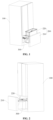


Classifications
-
- A—HUMAN NECESSITIES
- A47—FURNITURE; DOMESTIC ARTICLES OR APPLIANCES; COFFEE MILLS; SPICE MILLS; SUCTION CLEANERS IN GENERAL
- A47B—TABLES; DESKS; OFFICE FURNITURE; CABINETS; DRAWERS; GENERAL DETAILS OF FURNITURE
- A47B51/00—Cabinets with means for moving compartments up and down
-
- A—HUMAN NECESSITIES
- A47—FURNITURE; DOMESTIC ARTICLES OR APPLIANCES; COFFEE MILLS; SPICE MILLS; SUCTION CLEANERS IN GENERAL
- A47B—TABLES; DESKS; OFFICE FURNITURE; CABINETS; DRAWERS; GENERAL DETAILS OF FURNITURE
- A47B88/00—Drawers for tables, cabinets or like furniture; Guides for drawers
- A47B88/40—Sliding drawers; Slides or guides therefor
- A47B88/453—Actuated drawers
-
- A—HUMAN NECESSITIES
- A47—FURNITURE; DOMESTIC ARTICLES OR APPLIANCES; COFFEE MILLS; SPICE MILLS; SUCTION CLEANERS IN GENERAL
- A47B—TABLES; DESKS; OFFICE FURNITURE; CABINETS; DRAWERS; GENERAL DETAILS OF FURNITURE
- A47B88/00—Drawers for tables, cabinets or like furniture; Guides for drawers
- A47B88/40—Sliding drawers; Slides or guides therefor
- A47B88/453—Actuated drawers
- A47B88/457—Actuated drawers operated by electrically-powered actuation means
-
- A—HUMAN NECESSITIES
- A47—FURNITURE; DOMESTIC ARTICLES OR APPLIANCES; COFFEE MILLS; SPICE MILLS; SUCTION CLEANERS IN GENERAL
- A47B—TABLES; DESKS; OFFICE FURNITURE; CABINETS; DRAWERS; GENERAL DETAILS OF FURNITURE
- A47B88/00—Drawers for tables, cabinets or like furniture; Guides for drawers
- A47B88/90—Constructional details of drawers
-
- A—HUMAN NECESSITIES
- A47—FURNITURE; DOMESTIC ARTICLES OR APPLIANCES; COFFEE MILLS; SPICE MILLS; SUCTION CLEANERS IN GENERAL
- A47B—TABLES; DESKS; OFFICE FURNITURE; CABINETS; DRAWERS; GENERAL DETAILS OF FURNITURE
- A47B88/00—Drawers for tables, cabinets or like furniture; Guides for drawers
- A47B88/90—Constructional details of drawers
- A47B2088/901—Drawers having a lifting mechanism
-
- A—HUMAN NECESSITIES
- A47—FURNITURE; DOMESTIC ARTICLES OR APPLIANCES; COFFEE MILLS; SPICE MILLS; SUCTION CLEANERS IN GENERAL
- A47B—TABLES; DESKS; OFFICE FURNITURE; CABINETS; DRAWERS; GENERAL DETAILS OF FURNITURE
- A47B2210/00—General construction of drawers, guides and guide devices
- A47B2210/17—Drawers used in connection with household appliances
- A47B2210/175—Refrigerators or freezers
-
- A—HUMAN NECESSITIES
- A47—FURNITURE; DOMESTIC ARTICLES OR APPLIANCES; COFFEE MILLS; SPICE MILLS; SUCTION CLEANERS IN GENERAL
- A47B—TABLES; DESKS; OFFICE FURNITURE; CABINETS; DRAWERS; GENERAL DETAILS OF FURNITURE
- A47B88/00—Drawers for tables, cabinets or like furniture; Guides for drawers
- A47B88/70—Coupled drawers
- A47B88/75—Coupled drawers the secondary drawer being in or above the primary drawer
-
- F—MECHANICAL ENGINEERING; LIGHTING; HEATING; WEAPONS; BLASTING
- F25—REFRIGERATION OR COOLING; COMBINED HEATING AND REFRIGERATION SYSTEMS; HEAT PUMP SYSTEMS; MANUFACTURE OR STORAGE OF ICE; LIQUEFACTION SOLIDIFICATION OF GASES
- F25D—REFRIGERATORS; COLD ROOMS; ICE-BOXES; COOLING OR FREEZING APPARATUS NOT OTHERWISE PROVIDED FOR
- F25D23/00—General constructional features
- F25D23/02—Doors; Covers
- F25D23/021—Sliding doors
-
- F—MECHANICAL ENGINEERING; LIGHTING; HEATING; WEAPONS; BLASTING
- F25—REFRIGERATION OR COOLING; COMBINED HEATING AND REFRIGERATION SYSTEMS; HEAT PUMP SYSTEMS; MANUFACTURE OR STORAGE OF ICE; LIQUEFACTION SOLIDIFICATION OF GASES
- F25D—REFRIGERATORS; COLD ROOMS; ICE-BOXES; COOLING OR FREEZING APPARATUS NOT OTHERWISE PROVIDED FOR
- F25D25/00—Charging, supporting, and discharging the articles to be cooled
- F25D25/02—Charging, supporting, and discharging the articles to be cooled by shelves
- F25D25/024—Slidable shelves
- F25D25/025—Drawers
-
- F—MECHANICAL ENGINEERING; LIGHTING; HEATING; WEAPONS; BLASTING
- F25—REFRIGERATION OR COOLING; COMBINED HEATING AND REFRIGERATION SYSTEMS; HEAT PUMP SYSTEMS; MANUFACTURE OR STORAGE OF ICE; LIQUEFACTION SOLIDIFICATION OF GASES
- F25D—REFRIGERATORS; COLD ROOMS; ICE-BOXES; COOLING OR FREEZING APPARATUS NOT OTHERWISE PROVIDED FOR
- F25D25/00—Charging, supporting, and discharging the articles to be cooled
- F25D25/04—Charging, supporting, and discharging the articles to be cooled by conveyors
Definitions
- the present application relates to the field of household appliances, and in particular to a storage cabinet.
- Some high-grade refrigerators such as French-door refrigerators have a refrigerating compartment at an upper part and multi-layer straight pull-operated drawers at a lower part.
- a user is required to bend down or crouch in order to pick and place frozen foods from the straight pull-operated drawers and it easily causes discomfort to the waist of the user such as soreness and stiffness, or numbness in the lower leg, especially when the user organises the straight pull-operated drawers for a long time, which affects the user experience.
- the present application is intended to solve at least one of problems in the related art.
- the present application provides a storage cabinet, which not only can smoothly lift and lower a storage member and increase the volume rate of the storage cabinet, but also can automatically push and pull the storage member.
- an embodiment provides a storage cabinet, including:
- the base by disposing a lifting mechanism and an in-out mechanism on at least one side of the storage assembly, the base can extend out of or retracted into the cabinet body by starting the in-out mechanism, i.e., close to or far from the user when items are picked up or placed.
- the storage member can be lifted up or down with respect to the base by starting the lifting mechanism, thereby avoiding the user to bend down to pick up or place items and improving the user experience.
- lifting flexible cable and pulley assembly of the lifting mechanism is used to hoist the storage member in the present application, it is not only possible to achieve multi-point hoisting of the storage member on one side with the help of the pulley assembly, but it is also possible to use the flexibility of the lifting flexible cable itself to absorb the vibration generated by the lifting driver to avoid the vibration generated by the lifting driver from being transmitted to the storage member, and thus the storage member is smoothly lifted.
- the pulley assembly includes a plurality of fixed pulleys rotatably disposed on the base
- the lifting flexible cable includes a plurality of flexible cable segments having the same direction of transmission and being arranged in parallel between the plurality of the fixed pulleys, and the mounting positions are disposed on the flexible cable segments.
- the lifting flexible cable is annular
- the plurality of the fixed pulleys include:
- the number of the first fixed pulleys and the number of the second fixed pulleys are both two, and at least one third fixed pulley is disposed between two adjacent second fixed pulleys, and the transmission direction of the lifting flexible cable wrapped between the third fixed pulley and one of the second fixed pulleys is same as and parallel with the transmission direction of the lifting flexible cable wrapped between the other second fixed pulley and a corresponding first fixed pulley.
- the lifting flexible cable includes a first flexible cable and a second flexible cable which are both linear
- the pulley assembly includes a first movable pulley and a second movable pulley
- the mounting positions are disposed at the first movable pulley and the second movable pulley
- first ends of both the first flexible cable and the second flexible cable are fixed to the base, a second end of the first flexible cable is wrapped around the lifting driver after passing through the first movable pulley and a second end of the second flexible cable is wrapped around the lifting driver after passing through the second movable pulley.
- the lifting driver includes a motor and a drive reel and a driven reel both mounted on the base, the second end of the first flexible cable is wrapped around the drive reel and the second end of the second flexible cable is wrapped around the driven reel, a drive gear is fixed at an end of the drive reel, a driven gear engaged with the drive gear is fixed at an end of the driven reel; and the motor is connected to the drive reel for rotating the drive reel.
- the in-out mechanism includes:
- the in-out mechanism further includes at least one intermediate sliding rail, the first sliding rail being slidably connected to the second sliding rail through the intermediate sliding rail, at least one in-out movable pulley being rotatably mounted on the intermediate sliding rail, the in-out flexible cable located between the in-out movable pulley and the second sliding rail is wrapped around the in-out movable pulley.
- the in-out mechanism is disposed on both sides of the base, the first sliding rail is formed in a first connecting plate, the rotary wheel is mounted on the first connecting plate through a wheel sleeve; both in-out drivers are mounted on a second connecting plate, the second connecting plate is fixed between two first connecting plates.
- the two in-out drivers are integrated into an assembly including a synchronizing rod, an in-out motor and a gear assembly
- the in-out motor is fixed to the second connecting plate
- the synchronizing rod is rotatably mounted to the second connecting plate
- both ends of the synchronizing rod are fixedly connected to the two rotary wheels respectively
- an output shaft of the in-out motor is engaged with the synchronizing rod via transmission through the gear assembly.
- the in-out mechanism includes:
- the base by disposing a lifting mechanism and an in-out mechanism on at least one side of the storage assembly, the base can be driven to extend out of or retracted into the cabinet body by starting the in-out mechanism, i.e., approaching or withdrawing from the user when items are picked up or placed.
- the storage member can be lifted up or down with respect to the base by starting the lifting mechanism, thereby avoiding the user to bend down to pick up or place items and improving the user experience.
- lifting flexible cable and pulley assembly of the lifting mechanism is used to hoist the storage member in the present application, it is not only possible to achieve multi-point hoisting of the storage member on one side with the help of the pulley assembly, but it is also possible to use the flexibility of the lifting flexible cable itself to absorb the vibration generated by the lifting driver to avoid the vibration generated by the lifting driver from being transmitted to the storage member, and thus the storage member is smoothly lifted.
- the lifting mechanism has almost no effect on the volume rate of the cabinet due to small assembly area of the pulley assembly.
- orientation or positional relationships indicated by terms such as “center”, “longitudinal”, “lateral”, “upper”, “lower”, “bottom”, “inside”, “outside”, etc. are based on the orientation or positional relationship shown in the drawings, and are merely for the convenience of describing the embodiments of the present application and simplifying the description and thus is not to be construed as limiting the embodiments of the present application.
- the terms “first”, “second”, “third”, and the like are used for descriptive purposes only and are not to be construed as indicating or implying relative importance.
- connection with shall be understood broadly, for example, it may be either fixedly connected or detachably connected, or can be integrated; it may be mechanically connected, or electrically connected; it may be directly connected, or indirectly connected through an intermediate medium.
- connection shall be understood broadly, for example, it may be either fixedly connected or detachably connected, or can be integrated; it may be mechanically connected, or electrically connected; it may be directly connected, or indirectly connected through an intermediate medium.
- the first feature being located “on” or “under” the second feature means that the first feature is in direct contact with the second feature or the first feature is in contact with the second feature by an intervening media.
- the first feature being located “on”, “above” and “on top of' the second feature may mean that the first feature is directly on or above the second feature, or it simply means that the level of the first feature is higher than the second feature.
- the first feature being located “under”, “below” and “on bottom of” the second feature may mean that the first feature is directly under or below the second feature, or it simply means that the level of the first feature is lower than the second feature.
- an embodiment of the present application provides a storage cabinet, which includes a cabinet body 100, a storage assembly 200, an in-out mechanism 300 and a lifting mechanism 400, where a storage space is included in the cabinet body 100; the storage assembly 200 is disposed in the storage space and includes a base 210 and a storage member 220, the storage member 220 is movably disposed in the base 210; the in-out mechanism 300 is disposed on at least one side of the base 210; the in-out mechanism 300 is connected to the base 210 and the cabinet body 100, respectively, and configured to drive the base 210 to switch between a hidden position at which the base 100 is retracted into the storage space and an extended position at which the base 100 extends out of the storage space; and a lifting mechanism 400 is disposed on at least one side of the storage member 220; the lifting mechanism 400 includes a pulley assembly, a lifting flexible cable 410 and a lifting driver 420; the lifting flexible cable 410 is wrapped around the pulley assembly to
- the base 210 is a drawer located in the lower part of the French-door refrigerator, and the storage member 220 is a storage box inside the drawer.
- the user may first start the in-out mechanism 300 to slide the base 210 toward the user with respect to the cabinet body 100 until it reaches the extended position. Then, as shown in FIG. 1 , the user starts the lifting driver 420 to drive the lifting flexible cable 410 to smoothly lift the storage member 220 until the storage member 220 extends out of the base 210.
- the user may then restart the lifting driver 420 to drive the lifting flexible cable 410 to smoothly drop the storage member 220 down until the storage member 220 is retracted back into the base 210. Finally, the user restarts the in-out mechanism 300 to make the base 210 slide in the direction away from the user with respect to the cabinet body 100 until it reaches the hidden position. It should be noted that in order to improve the aesthetics and reduce the risk of the pulley assembly being stuck by foreign items, as shown in FIG.
- the side wall of the base 210 includes a cavity
- the lifting mechanism 400 is disposed in the cavity of the base 210
- the side wall of the base 210 towards the storage member 220 includes strip-shaped holes corresponding to the mounting positions 401 and the strip-shaped holes extend along the height direction of the base 210.
- the base 210 can be driven to extend out of or retracted into the cabinet body 100 by starting the in-out mechanism 300, i.e., approaching or withdrawing from the user when items are picked up or placed.
- the storage member 220 can be lifted up or down with respect to the base 210 by starting the lifting mechanism 400, thereby avoiding the user to bend down to pick up or place items and improving the user experience.
- lifting flexible cable 410 and pulley assembly of the lifting mechanism 400 is used to hoist the storage member 220 in the embodiment, it is not only possible to achieve multi-point hoisting of the storage member 220 on one side with the help of the pulley assembly, but it is also possible to use the flexibility of the lifting flexible cable 410 itself to absorb the vibration generated by the lifting driver 420 so as to avoid the vibration generated by the lifting driver 420 from being transmitted to the storage member 220, and thus the storage member 220 is smoothly lifted.
- the lifting mechanism 400 has almost no effect on the volume rate of the cabinet due to small assembly area of the pulley assembly.
- the pulley assembly includes a plurality of fixed pulleys rotatably disposed on the base 210
- the lifting flexible cable 410 includes a plurality of flexible cable segments having the same direction of transmission and being arranged in parallel between the plurality of the fixed pulleys
- the mounting positions 401 are disposed on the flexible cable segments.
- the plurality of fixed pulleys includes a plurality of first fixed pulleys 431, a plurality of second fixed pulleys 432 and at least one third fixed pulley 433 disposed between two adjacent second fixed pulleys 432.
- the pulley assembly is a set of fixed pulleys including a first fixed pulley set, a second fixed pulley set and a third fixed pulley set.
- the second fixed pulley set is disposed below the first fixed pulley set and is connected to the first fixed pulley set via transmission through the lifting flexible cable 410 and the third fixed pulley set is disposed between the first fixed pulley set and the second fixed pulley set.
- the lifting flexible cable 410 wrapped between two adjacent second fixed pulleys 432 is wound through the corresponding third fixed pulley 433 and thus the lifting flexible cable 410 includes a plurality of flexible cable segments between the first fixed pulley set and the second fixed pulley assembly.
- the lifting driver 420 is connected to the first fixed pulleys 431, the second fixed pulleys 432, or the third fixed pulley 433.
- the lifting driver 420 may be, but not limited to, a motor or a turning handle.
- the working principle of the lifting mechanism 400 in the embodiment of the present application is illustrated below by taking two mounting positions 401, i.e., the pulley assembly including two first fixed pulleys 431, two second fixed pulleys 432 and one third fixed pulley 433 as an example.
- the first fixed pulleys 431, the third fixed pulley 433 and the second fixed pulleys 432 are disposed successively from top to bottom, the third fixed pulley 433 is disposed close to the first fixed pulleys 431, and the first fixed pulley 431 on the left, the second fixed pulley 432 on the left, the third fixed pulley 433, the second fixed pulley 432 on the right and the first fixed pulley 431 on the right are sequentially connected through the lifting flexible cable 410 via transmission.
- the lifting flexible cable 410 wrapped between the third fixed pulley 433 and one of the second fixed pulleys 432, and the lifting flexible cable 410 wrapped between the other of the second fixed pulleys 432 and the corresponding first fixed pulley 431 have the same direction of transmission and are arranged in parallel.
- the lifting flexible cable 410 between the second fixed pulley 432 on the right and the first fixed pulley 431 on the right and the lifting flexible cable 410 between the third fixed pulley 433 and the second fixed pulley 432 on the left are arranged in parallel and have the same direction of transmission, and can be referred to as two flexible cable segments. Since these two flexible cable segments extend in the vertical direction, the storage member 220 can be lifted in the vertical direction after the side wall of the storage member 220 is fixed to these two flexible cable segments by a connector.
- the lifting driver 420 drives the lifting flexible cable 410 to entirely rotate counterclockwise, the two flexible cable segments, i.e., the lifting flexible cable 410 wrapped between the third fixed pulley 433 and the second fixed pulley 432 on the left, and the lifting flexible cable 410 wrapped between the second fixed pulley 432 on the right and the first fixed pulley 431 on the right, move upward to drive the storage member 220 to move upward vertically.
- both flexible cable segments move downward to drive the storage member 220 to move downward vertically.
- the lifting flexible cable 410 between the first fixed pulley 431 on the left and the second fixed pulley 432 on the left and the lifting flexible cable 410 between the third fixed pulley 433 and the second fixed pulley 432 on the right are arranged in parallel and have the same direction of transmission, and can be referred to as two flexible cable segments.
- the movement path of the storage member 220 is inclined upward or inclined downward after the side wall of the storage member 220 is fixed to these two flexible cable segments through the connector.
- the position of the flexible cable segments can be determined according to the actual situations.
- the lifting flexible cable 410 wrapped between the first fixed pulley 431 on the left and the second fixed pulley 432 on the left and the lifting flexible cable 410 wrapped between the third fixed pulley 433 and the second fixed pulley 432 on the right may also be not parallel, i.e., are not referred to as flexible cable segments when the lifting flexible cable 410 wrapped between the second fixed pulley 432 on the right and the first fixed pulley 431 on the right and the lifting flexible cable 410 wrapped between the third fixed pulley 433 and the second fixed pulley 432 on the left both extend in the vertical direction.
- the lifting mechanism 400 can provide lifting of the storage assembly 200 in the vertical direction, instead of in the inclined direction.
- a plurality of third fixed pulleys 433 can be disposed between the two second fixed pulleys 432.
- the pulley assembly includes two first fixed pulleys 431, two second fixed pulleys 432, and two third fixed pulleys 433.
- the first fixed pulleys 431, the third fixed pulleys 433 and the second fixed pulleys 432 are disposed in order from top to bottom, the third fixed pulleys 433 are disposed close to the first fixed pulleys 431, and the first fixed pulley 431 on the left, the second fixed pulley 432 on the left, the third fixed pulley 433 on the left, the third fixed pulley 433 on the right, the second fixed pulley 432 on the right and the first fixed pulley 431 on the right are sequentially connected through lifting flexible cable 410 via transmission and the lifting cable 410 form an inverted "concave" shape.
- the lifting flexible cable 410 between the third fixed pulley 433 on the left and the second fixed pulley 432 on the left and the lifting flexible cable 410 between the third fixed pulley 432 on the right and the first fixed pulley 431 on the right are arranged in parallel and have the same direction of transmission, and can be referred to as two flexible cable segments.
- the lifting driver 420 drives the lifting flexible cable 410 to entirely rotate counterclockwise, the two flexible cable segments, i.e., the lifting flexible cable 410 wrapped between the third fixed pulley 433 on the left and the second fixed pulley 432 on the left, and the lifting flexible cable 410 wrapped between the second fixed pulley 432 on the right and the first fixed pulley 431 on the right, move upward to drive the storage member 220 to move upward vertically.
- both flexible cable segments move downward to drive the storage member 220 to move downward vertically.
- the pulley assembly includes two first fixed pulleys 431, three second fixed pulleys 432, and two third fixed pulleys 433.
- the lifting flexible cable 410 between the third fixed pulley 433 on the left and the second fixed pulley 432 on the left, the lifting flexible cable 410 between the third fixed pulley 433 on the right and the second fixed pulley 432 in the middle and the lifting flexible cable 410 between the first fixed pulley 431 on the right and the second fixed pulley 432 on the right are arranged in parallel and have the same direction of transmission, and can be referred to as three flexible cable segments. Both ends and the central part of the side wall of the base 210 can be fixed to the three flexible segments respectively through the connectors.
- a tensioner 440 is disposed on the lifting flexible cable 410 as shown in FIGS. 5 and 7 .
- Each lifting flexible cable 410 may be, but not limited to, a synchronous belt or a chain.
- the first fixed pulleys 431, the second fixed pulleys 432 and the third fixed pulleys 433 are all gears engaged with the synchronous belt.
- the first fixed pulleys 431, the second fixed pulleys 432 and the third fixed pulleys 433 are all chain wheels engaged with the chain.
- first fixed pulleys 431, the second fixed pulleys 432 and the third fixed pulleys 433 can be fixed pulleys having the same size, that is, the size and material of all three are the same.
- the lifting cable 410 may be linear, as well as being annular.
- the lifting flexible cable 410 includes a first flexible cable 411 and a second flexible cable 412, which are both linear, and the pulley assembly includes a first movable pulley 434 and a second movable pulley 435, and the mounting positions 401 is disposed at the first movable pulley 434 and the second movable pulley 435.
- First ends of the first flexible cable 411 and the second flexible cable 412 are fixed to the base 210, and the second end of the first flexible cable 411 is wrapped around the lifting driver 420 after being wound around first movable pulley 434 and the second end of the second flexible cable 412 is wrapped around the lifting driver 420 after being wound around second movable pulley 435.
- the lifting driver includes a motor and a drive reel 421 and a driven reel 422 mounted on the base 210, the second end of the first flexible cable 411 is wrapped around the drive reel 421 and the second end of the second flexible cable 412 is wrapped around the driven reel 422, a drive gear 423 is fixed at an end of the drive reel 421, a driven gear 424 engaged with the drive gear 423 is fixed at an end of the driven reel 422; and the motor is connected to the drive reel 421 for driving the drive reel 421 to rotate.
- the first flexible cable 411 and the second flexible cable 412 are released from the drive reel 421 and the driven reel 422 respectively, and then drive the first movable pulley 434 and the second movable pulley 435 to move downward synchronously.
- the base 210 fixed with the first movable pulley 434 and the second movable pulley 435 can move up and down.
- synchronous rotation of the drive reel 421 and the driven reel 422 it can be implemented by increasing the number of motors, i.e., by disposing two motors in addition to the drive gear 423 and the driven gear 424.
- the two motors are connected to the drive reel 421 and the driven reel 422 respectively, and the synchronous rotation of the drive reel 421 and the driven reel 422 can be implemented by precisely controlling an on-off time and the rotational speed of the two motors, and then the synchronous and simultaneous movement of the first movable pulley 434 and the second movable pulley 435 can be implemented.
- a lifting mechanism 400 is disposed at both sides of the base 210, two lifting drivers 420 integrated, that is, the two lifting mechanisms 400 share one lifting driver 420.
- the lifting flexible cable 410 is annular and the lifting driver 420 is the motor
- pulley assemblies of the two lifting mechanisms are coupled through a transmission rod 450
- the output shaft of the motor is connected to the transmission rod 450 and the motor drives the two lifting flexible cables 410 to make transmission through the transmission rod 450.
- a side of the storage member 220 backward to the lifting mechanism 400 is slidably connected to the guide rail.
- a sliding slot extending along a height direction of the guide rail is disposed in the guide rail and a projection being engaged slidably with the sliding slot is disposed on the side wall of the storage member 220.
- a flange extending along a height direction of the guide rail is disposed in the guide rail and a projection being engaged slidably with a groove is disposed on the side wall of the storage member 220.
- the lifting mechanisms 400 on both sides of the base 210 not only enables multi-point hoisting on both sides of the storage member 220, but also improves the stability of the storage member 220 in the process of moving up and down, and reduces the assembly occupation area without disposing additional guide rails.
- in-out mechanism 300 can have various structural forms, such as: In a first form, as shown in FIGS. 11 and 13 , in-out mechanism 300 includes a first sliding rail 310, a second sliding rail 320, an in-out flexible cable 350, an in-out fixed pulley 341, a rotary wheel 342 and an in-out driver in which the first sliding rail 310 is fixed to the cabinet body 100, the second sliding rail 320 is fixed to the base 210, the second sliding rail 320 is slidably mounted to the first sliding rail 310 for sliding with respect to the first sliding rail 320, the in-out fixed pulley 341 is rotatably mounted on the first sliding rail 310, the rotary wheel 342 is rotatably disposed in the cabinet body 100 or on the first sliding rail 310, the in-out flexible cable 350 is wrapped around the rotary wheel 342 and the in-out fixed pulley 341; both ends of the in-out flexible cable 350 are connected to
- the in-out driver is driven to drive the rotary wheel 342 to rotate when it is necessary to pick up or place an item from the storage member 220. Since the in-out flexible cable 350 is wrapped around the rotary wheel 342 and the in-out fixed pulley 341, both ends of the in-out flexible cable 350 are connected to the second sliding rail 320, while the first sliding rail 310 is fixed to the cabinet body 100, the second sliding rail 320 is fixed to the base 210, and thus the second sliding rail 320 will be driven to make linear motion with respect to the first sliding rail 310 through the in-out flexible cable 350 during the rotation process of the rotary wheel 342.
- the base 210 slides with respect to the cabinet body 100 in a direction approaching or withdrawing from the user, i.e., the base 210 is switched with respect to the cabinet body 100 in the hidden position and the extended position.
- the rotary wheel 342 will only drive in-out fixed pulley 341 to rotate through the in-out flexible cable 350, and will not drive in-out fixed pulley 341 to change spatial position.
- the number of in-out fixed pulleys 341 can be either one or more. For example, as shown in FIG.
- the in-out fixed pulley 341 adjacent to the rotary wheel 342, i.e., the in-out fixed pulley 341 located on the right side in FIG. 14 corresponds to a cable-passing pulley, and the presence of the in-out fixed pulley 341 can keep the in-out flexible cable 350 located between the in-out fixed pulley 341 and the other in-out pulley 341 in horizontal.
- the move direction of the second sliding rail 320 with respect to the first sliding rail 310 is also different due to different rotation directions of the rotary wheel 342.
- the in-out flexible cable 350 drives the second sliding rail 320 to move to the right with respect to the first sliding rail 310.
- the in-out flexible cable 350 drives the second sliding rail 320 to move to the left with respect to the first sliding rail 310.
- the in-out mechanism 300 in this embodiment not only has a simple structure and occupies little space, but also is very convenient to disassemble the in-out mechanism 300 since only the disassembly of the rotary wheel 342, the in-out fixed pulley 341 and the in-out driving component is involved.
- a sliding block 380 is fixed on the second sliding rail 320 and both ends of the in-out flexible cable 350 are fixed to the sliding block 380.
- the fixing method between the sliding block 380 and the in-out flexible cable 350 is not limited, for example, it can be binding, threaded connection or welding.
- the sliding block 380 can be disposed at the end of the second sliding rail 320 close to the rotary wheel 342.
- the ends of the in-out flexible cable 350 can also be fixed through a fixer 390 and the fixer 390 fixes the in-out flexible cable 350 to the second sliding rail 320 by screws.
- the in-out mechanism 300 also includes at least one intermediate sliding rail 330, the first sliding rail 310 is slidably connected to the second sliding rail 320 through the intermediate sliding rail 330, at least one in-out movable pulley 343 is rotatably mounted on the intermediate sliding rail 330 and the in-out flexible cable 350 located between the in-out fixed pulley 341 and the second sliding rail 320 is wound around the in-out movable pulley 343.
- the number of intermediate sliding rails 330 is multiple, two adjacent intermediate sliding rails 330 are slidably connected to be suitable for two intermediate sliding rails 330 to slide with respect to each other.
- an intermediate sliding rail 330 is disposed between the first sliding rail 310 and the second sliding rail 320 and the upper and lower edges of the intermediate sliding rail 330 are slidably mounted on the first sliding rail 310 and the second sliding rail 320, respectively.
- a first groove extending along the length of the first sliding rail 310 is disposed on the side of the first sliding rail 310 toward the intermediate sliding rail 330
- a second groove extending along the length of the second sliding rail 320 is disposed on the side of the second sliding rail 320 toward the intermediate sliding rail 330 and the upper and lower edges of the intermediate sliding rail 330 are embedded in the second groove and the first groove.
- a first flange extending along length of the first sliding rail 310 can also be disposed on the side of the first sliding rail 310 toward the intermediate sliding rail 330
- a second flange extending along the length of the second sliding rail 320 can also be disposed on the side of the second sliding rail 320 toward the intermediate sliding rail 330
- third grooves extending along the length of the intermediate sliding rail 330 are disposed at top and bottom sides of the intermediate sliding rail 330
- the first flange and the second flange can be slidably embedded in the corresponding third grooves respectively.
- In-out movable pulleys 343 are rotatably mounted on both ends of the intermediate sliding rail 330 and the in-out flexible cable 350 located between the in-out fixed pulley 341 and the second sliding rail 320 is first wound around the in-out movable pulley 343 away from the back plate of the cabinet body 100, i.e., the right side, and then wound around the in-out movable pulley 343 close to the back plate of the cabinet body 100, i.e., the left side.
- the in-out flexible cable 350 located between the in-out fixed pulley 341 and the second sliding rail 320 includes a first flexible cable segment 351, a second flexible cable segment 352 and a third flexible cable segment 353 in which the first flexible cable segment 351 is located between the in-out fixed pulley 341 and the in-out movable pulley 343 away from the back plate of the cabinet body 100, the second flexible cable segment 352 is located between the two in-out movable pulleys 343, and the third flexible cable segment 353 is located between the in-out movable pulley 343 close to the back plate of the cabinet body 100 and the second sliding rail 320.
- the first flexible cable segment 351, the second flexible cable segment 352 and the third flexible cable segment 353 can have an included angle.
- the first flexible cable segment 351, the second flexible cable segment 352 and the third flexible cable segment 353 can be arranged parallel to each other by adjusting the size and/or position of the rotary wheel 342, the in-out fixed pulley 341 and the in-out movable pulley 343.
- the in-out flexible cable 350 located between the in-out fixed pulley 341 and the second sliding rail 320 is sequentially wound through the two in-out movable pulleys 343.
- the rotary wheel 342 is rotated counterclockwise as shown in FIGS.
- the in-out flexible cable 350 located between the rotary wheel 342 and the in-out fixed pulley 350 moves to the right to further drive the in-out fixed pulley 341 to move counterclockwise;
- the first flexible cable segment 351 moves to the left to drive the in-out movable pulley 343 on the right to rotate clockwise;
- the second flexible cable segment 352 moves to the right to drive the in-out movable pulley 343 on the left to move counterclockwise;
- the third flexible cable segment 353 moves to the left to drive the second sliding rail 320 to move to the left.
- the in-out flexible cable 350 between the rotary wheel 342 and the second sliding rail 320 becomes longer, and the in-out flexible cable 350 between the in-out movable pulley 343 on the left and the second sliding rail 320 becomes shorter.
- the second sliding rail 320 moves to the left to the limit position, if the rotary wheel 342 continues to rotate counterclockwise, the first flexible cable segment 351 will drive the in-out movable pulley 343 on the right to move to the left, and then make the intermediate sliding rail 330 move to the left because the first flexible cable segment 351 moves to the left.
- the in-out flexible cable 350 located between the in-out fixed pulley 341 and the in-out movable pulley 343 on the right becomes shorter, and the in-out flexible cable 350 located between the rotary wheel 342 and the second sliding rail 320 continues to become longer.
- the in-out flexible cable 350 located between the rotary wheel 342 and the second sliding rail 320 moves to the right, which in turn drives the second sliding rail 320 to move to the right.
- the in-out flexible cable 350 between the rotary wheel 342 and the second sliding rail 320 becomes shorter, and the in-out flexible cable 350 between the in-out movable pulley 343 on the left and the second sliding rail 320 becomes longer.
- the third flexible cable segment 353 will also move to the right, and drive the in-out movable pulley 343 to move to the right to drive the intermediate sliding rail 330 to move to the right because the in-out flexible cable 350 located between the rotary wheel 342 and the second sliding rail 320 continues to move to the right.
- the in-out flexible cable 350 between the in-out fixed pulley 341 and the in-out movable pulley 343 on the right becomes longer, and the in-out flexible cable 350 between the rotary wheel 342 and the second sliding rail 320 continues to become shorter.
- the rotary wheel 342 drives the second sliding rail 320 to make linear motion through the in-out flexible cable 350 first.
- the rotary wheel 342 continues to drive the intermediate sliding rails 330 close to the second sliding rail 320 to make linear motion through the in-out flexible cable 350.
- the rotary wheel 342 continues to drive another intermediate sliding rail 330 adjacent to it to make linear motion through the in-out flexible cable 350, and so on.
- in-out mechanisms 300 are disposed on both sides of the base 210, and in order to facilitate modular installation, transportation and production of in-out mechanism 300, the first sliding rail 310 is disposed in the first connecting plate 371, the rotary wheel 342 is mounted in the first connecting plate 371 through the wheel sleeve, and two in-out drivers are mounted in the second connecting plate 372, that is to say, the second sliding rail 320, the rotary wheel 342, the in-out fixed pulley 341 and the in-out flexible cable 350 are directly or indirectly mounted on the first connecting plate 371 to constitute a first module, and the in-out driver is mounted on the second connecting plate 372 to constitute a second module.
- the first module is first assembled, i.e., the rotary wheel 342 and the in-out fixed pulley 341 are mounted on the first connecting plate 371, the second sliding rail 320 is slidably connected to the first sliding rail 310, and the in-out flexible cable 350 is wrapped around the rotary wheel 342 and the in-out fixed pulley 341, and both ends of the in-out flexible cable 350 are connected to the second sliding rail 320.
- the second module is then assembled, i.e., the two in-out drivers are fixed to the second connecting plate 372.
- the in-out drivers are connected to the corresponding rotary wheels 342.
- the two first modules are mounted on the left and right sides of the base 210, i.e., the first connecting plate 371 is fixed to the side wall of the cabinet body 100 and the second sliding rail 320 is fixed to the side wall of the base 210.
- the second connecting plate 372 can either be fixed directly on the front or rear side of the base 210, or both ends of the second connecting plate 372 can be fixed directly on the first connecting plate 371 on the left and right sides.
- the first connecting plate 371 and the second connecting plate 372 can be, but not limited to, sheet metal parts.
- the first connecting plate 371 and the second connecting plate 372 can be connected by engaging, bolted connection, welding, gluing, etc.
- the two in-out drivers are integrated into an assembly including a synchronizing rod 362, an in-out motor 361 and a gear assembly, the in-out motor 361 is fixed to the second connecting plate, the synchronizing rod 362 is rotatably mounted to the second connecting plate 372, both ends of the synchronizing rod 362 are fixedly connected to the two rotary wheels 342 and an output shaft of the in-out motor 361 is engaged with the synchronizing rod via transmission through the gear assembly.
- the gear assembly includes a first gear and a second gear, the first gear is fixed to the output shaft of the inlet and outlet motor, and the second gear is sleeved on the synchronizing rod 362 and is fixedly connected to the synchronizing rod 362.
- the in-out mechanism 300 includes a first sliding rail 310, a second sliding rail 320, an intermediate sliding rail 330, an in-out flexible cable 350, a first connector 461 and a second connector 462 in which the first sliding rail 310 is fixed to the cabinet body 100, the second sliding rail 320 is fixed to the base 210, upper and lower edges of the intermediate sliding rail 330 slidably mounted on the first sliding rail 310 and the second sliding rail 320, in-out movable pulleys 343 are rotatably mounted on both ends of the intermediate sliding rail 330, the in-out flexible cable 350 is wrapped around the two in-out movable pulleys 343, the first connector 461 is fixedly connected to the front end of the first sliding rail 310 and the in-out flexible cable 350, the second connector 462 is fixedly connected to the rear end of the second sliding rail 320 and the in-out flexible cable 350, and the in-out driver is used to drive the in-out driver
- each in-out flexible cable 350 may be, but not limited to, a synchronous belt or a chain.
- the in-out movable pulley 343 is a gear engaged with the synchronous belt.
- the in-out movable pulley 343 is a chain wheel engaged with the chain.
- In-out mechanisms 300 are disposed on both sides of the base 210.
- the two in-out drivers can be integrated into an assembly including a synchronizing rod 362, an in-out motor 361 and a gear assembly. Both ends of the synchronizing rod 362 are coupled with the in-out movable pulley 343 on both sides, and the output shaft of the in-out motor 361 is coupled with the synchronizing rod 362 through the gear assembly.
- the first sliding rail 310 is disposed on the first connecting plate 371, and the second sliding rail 320 is slidably connected to the first sliding rail 310 through the intermediate sliding rail 330. That is, the second sliding rail 320, the intermediate sliding rail 330, the in-out flexible cable 350, and the in-out movable pulley 343 are directly or indirectly mounted on the first connecting plate 371 to constitute the first module.
- the in-out drivers mounted on the second connecting plate 372 constitute the second module.
- racks extending in the retraction and extension directions of the base 210 are fixed on the bottom and/or side walls of the base 210, a gear engaged with the rack is disposed on the cabinet body 100 and the in-out driver, such as a motor is connected to the gear.
- the in-out driver such as a motor is connected to the gear.
- a moving block is fixed on bottom and/or side wall of the base 210, a screw is rotatably mounted on the cabinet body 100, and the axial direction of the screw is parallel to the retraction and extension directions of the base 210 with respect to the cabinet body 100.
- a threaded hole in threaded connection with the screw and passing through the moving block is disposed laterally in the moving block and the in-out driver is connected to the screw for driving the screw to rotate.
Landscapes
- Combinations Of Kitchen Furniture (AREA)
- Warehouses Or Storage Devices (AREA)
Abstract
Description
- The present application claims priority to
Chinese application No. 202111165662.0 filed on September 30, 2021 - The present application relates to the field of household appliances, and in particular to a storage cabinet.
- Some high-grade refrigerators, such as French-door refrigerators have a refrigerating compartment at an upper part and multi-layer straight pull-operated drawers at a lower part. A user is required to bend down or crouch in order to pick and place frozen foods from the straight pull-operated drawers and it easily causes discomfort to the waist of the user such as soreness and stiffness, or numbness in the lower leg, especially when the user organises the straight pull-operated drawers for a long time, which affects the user experience.
- The present application is intended to solve at least one of problems in the related art. The present application provides a storage cabinet, which not only can smoothly lift and lower a storage member and increase the volume rate of the storage cabinet, but also can automatically push and pull the storage member.
- According to the present application, an embodiment provides a storage cabinet, including:
- a cabinet body in which a storage space is included; and
- a storage assembly, disposed in the storage space; the storage assembly including a base and a storage member, the storage member being movably disposed in the base;
- a in-out mechanism, disposed on at least one side of the base; the in-out mechanism being connected to the base and the cabinet body, respectively, and configured to drive the base to switch between a hidden position at which the base is retracted into the storage space and an extended position at which the base extends out of the storage space; and
- a lifting mechanism, disposed on at least one side of the storage member; the lifting mechanism including a pulley assembly, a lifting flexible cable and a lifting driver; the lifting flexible cable being wrapped around the pulley assembly to form a plurality of mounting positions synchronously moving in the same direction on the lifting flexible cable and/or the pulley assembly, the storage member being mounted on each mounting position; the lifting driver being fixed to the base for driving the lifting flexible cable to move up and down the storage member with respect to the base.
- According to the storage cabinet in an embodiment of the present application, by disposing a lifting mechanism and an in-out mechanism on at least one side of the storage assembly, the base can extend out of or retracted into the cabinet body by starting the in-out mechanism, i.e., close to or far from the user when items are picked up or placed. On this basis, the storage member can be lifted up or down with respect to the base by starting the lifting mechanism, thereby avoiding the user to bend down to pick up or place items and improving the user experience. In addition, since lifting flexible cable and pulley assembly of the lifting mechanism is used to hoist the storage member in the present application, it is not only possible to achieve multi-point hoisting of the storage member on one side with the help of the pulley assembly, but it is also possible to use the flexibility of the lifting flexible cable itself to absorb the vibration generated by the lifting driver to avoid the vibration generated by the lifting driver from being transmitted to the storage member, and thus the storage member is smoothly lifted.
- According to an embodiment of the present application, the pulley assembly includes a plurality of fixed pulleys rotatably disposed on the base, the lifting flexible cable includes a plurality of flexible cable segments having the same direction of transmission and being arranged in parallel between the plurality of the fixed pulleys, and the mounting positions are disposed on the flexible cable segments.
- According to an embodiment of the present application, the lifting flexible cable is annular, and the plurality of the fixed pulleys include:
- a first set of fixed pulley including a plurality of first fixed pulleys,
- a second set of fixed pulley, disposed below the first set of fixed pulley and connected to the first set of fixed pulley via transmission through the lifting flexible cable, the second set of fixed pulley including a plurality of second fixed pulleys;
- a third set of fixed pulley disposed between the first set of fixed pulley and the second set of fixed pulley, where the third set of fixed pulley includes at least one third fixed pulley disposed between two adjacent second fixed pulleys; the lifting flexible cable wrapped between the two adjacent second fixed pulleys is wrapped around a corresponding third fixed pulley and thus the lifting flexible cable includes a plurality of the flexible cable segments between the first set of fixed pulley and the second set of fixed pulley; and
- the lifting driver is connected to the first fixed pulley, the second fixed pulley or the third fixed pulley.
- According to an embodiment of the present application, the number of the first fixed pulleys and the number of the second fixed pulleys are both two, and at least one third fixed pulley is disposed between two adjacent second fixed pulleys, and the transmission direction of the lifting flexible cable wrapped between the third fixed pulley and one of the second fixed pulleys is same as and parallel with the transmission direction of the lifting flexible cable wrapped between the other second fixed pulley and a corresponding first fixed pulley.
- According to an embodiment of the present application, the lifting flexible cable includes a first flexible cable and a second flexible cable which are both linear, the pulley assembly includes a first movable pulley and a second movable pulley, the mounting positions are disposed at the first movable pulley and the second movable pulley; first ends of both the first flexible cable and the second flexible cable are fixed to the base, a second end of the first flexible cable is wrapped around the lifting driver after passing through the first movable pulley and a second end of the second flexible cable is wrapped around the lifting driver after passing through the second movable pulley.
- According to an embodiment of the present application, the lifting driver includes a motor and a drive reel and a driven reel both mounted on the base, the second end of the first flexible cable is wrapped around the drive reel and the second end of the second flexible cable is wrapped around the driven reel, a drive gear is fixed at an end of the drive reel, a driven gear engaged with the drive gear is fixed at an end of the driven reel; and the motor is connected to the drive reel for rotating the drive reel.
- According to an embodiment of the present application, the in-out mechanism includes:
- a first sliding rail fixed to the cabinet body,
- a second sliding rail fixed to the base, the second sliding rail being slidably mounted to the first sliding rail for sliding with respect to the first sliding rail,
- an in-out fixed pulley rotatably mounted on the first sliding rail,
- a rotary wheel rotatably disposed in the cabinet body or on the first sliding rail,
- an in-out flexible cable wrapped around the rotary wheel and the in-out fixed pulley; both ends of the in-out flexible cable being connected to the second sliding rail, and
- an in-out driver for rotating the rotary wheel.
- According to an embodiment of the present application, the in-out mechanism further includes at least one intermediate sliding rail, the first sliding rail being slidably connected to the second sliding rail through the intermediate sliding rail, at least one in-out movable pulley being rotatably mounted on the intermediate sliding rail, the in-out flexible cable located between the in-out movable pulley and the second sliding rail is wrapped around the in-out movable pulley.
- According to an embodiment of the present application, the in-out mechanism is disposed on both sides of the base, the first sliding rail is formed in a first connecting plate, the rotary wheel is mounted on the first connecting plate through a wheel sleeve; both in-out drivers are mounted on a second connecting plate, the second connecting plate is fixed between two first connecting plates.
- According to an embodiment of the present application, the two in-out drivers are integrated into an assembly including a synchronizing rod, an in-out motor and a gear assembly, the in-out motor is fixed to the second connecting plate, the synchronizing rod is rotatably mounted to the second connecting plate, both ends of the synchronizing rod are fixedly connected to the two rotary wheels respectively and an output shaft of the in-out motor is engaged with the synchronizing rod via transmission through the gear assembly.
- According to an embodiment of the present application, the in-out mechanism includes:
- a first sliding rail, fixed to the cabinet body,
- a second sliding rail, fixed to the base,
- an intermediate sliding rail, the upper and lower edges of the intermediate sliding rail being slidably mounted on the first sliding rail and the second sliding rail, respectively; in-out movable pulleys being rotatably mounted on both ends of the intermediate sliding rail,
- an in-out flexible cable wrapped around two in/out movable pulleys,
- a first connector fixedly connected to a front end of the first sliding rail and to the in-out flexible cable respectively,
- a second connector fixedly connected to a rear end of the second sliding rail and to the in-out flexible cable respectively, and
- an in-out driver for driving the in-out movable pulley to rotate.
- One or more solutions in the embodiments of the present application mentioned above have at least one of the following effects.
- According to the storage cabinet in the present application, by disposing a lifting mechanism and an in-out mechanism on at least one side of the storage assembly, the base can be driven to extend out of or retracted into the cabinet body by starting the in-out mechanism, i.e., approaching or withdrawing from the user when items are picked up or placed. On this basis, the storage member can be lifted up or down with respect to the base by starting the lifting mechanism, thereby avoiding the user to bend down to pick up or place items and improving the user experience. In addition, since lifting flexible cable and pulley assembly of the lifting mechanism is used to hoist the storage member in the present application, it is not only possible to achieve multi-point hoisting of the storage member on one side with the help of the pulley assembly, but it is also possible to use the flexibility of the lifting flexible cable itself to absorb the vibration generated by the lifting driver to avoid the vibration generated by the lifting driver from being transmitted to the storage member, and thus the storage member is smoothly lifted. In addition, the lifting mechanism has almost no effect on the volume rate of the cabinet due to small assembly area of the pulley assembly.
- The additional aspects and advantages of the present application will be partially given in the following description, and some thereof will become obvious from the following description, or be understood through the practice of the present application.
- In order to more clearly illustrate solutions disclosed in the embodiments of the present application or the prior art, the drawings used in the descriptions of the embodiments or the prior art will be briefly described below. The drawings in the following description are only certain embodiments of the present application, and other drawings can be obtained according to the drawings without any creative work for those skilled in the art.
-
FIG. 1 is a perspective schematic diagram of a storage cabinet according to an embodiment of the present application; -
FIG. 2 is a perspective schematic diagram of a storage cabinet according to an embodiment of the present application; -
FIG. 3 is a left schematic diagram of a storage cabinet according to an embodiment of the present application; -
FIG. 4 is a longitudinal cross-sectional diagram of a storage assembly according to an embodiment of the present application; -
FIG. 5 is a perspective schematic diagram of a lifting mechanism according to an embodiment of the present application; -
FIG. 6 is a front schematic diagram of a lifting mechanism according to an embodiment of the present application; -
FIG. 7 is a first perspective schematic diagram of another lifting mechanism according to an embodiment of the present application; -
FIG. 8 is a second perspective schematic diagram of another lifting mechanism according to an embodiment of the present application; -
FIG. 9 is a front schematic diagram of another lifting mechanism according to an embodiment of the present application; -
FIG. 10 is a front schematic diagram of yet another lifting mechanism according to an embodiment of the present application; -
FIG. 11 is a side schematic diagram of an in-out mechanism according to an embodiment of the present application; -
FIG. 12 is a first perspective schematic diagram of an in-out mechanism according to an embodiment of the present application; -
FIG. 13 is a second perspective schematic diagram of an in-out mechanism according to an embodiment of the present application; -
FIG. 14 is a perspective schematic diagram of another in-out mechanism according to an embodiment of the present application; -
FIG. 15 is a top schematic diagram of another in-out mechanism according to an embodiment of the present application; -
FIG. 16 is a first perspective schematic diagram of yet another in-out mechanism according to an embodiment of the present application; -
FIG. 17 is a second perspective schematic diagram of yet another in-out mechanism according to an embodiment of the present application; - Reference numerals:
- 100 cabinet body; 200 storage assembly; 210 base; 220 storage member; 300 an in-out mechanism;
- 310 first sliding rail; 320 second sliding rail; 330 intermediate sliding rail; 341 in-out fixed pulley;
- 342 rotary wheel; 343 in-out movable pulley; 350 in-out flexible cable; 351 first flexible cable segment;
- 352 second flexible cable segment; 353 third flexible cable segment; 361 in-out motor; 362 synchronizing rod;
- 371 first connecting plate; 372 second connecting plate; 380 sliding block; 390 fixer;
- 400 lifting mechanism; 401 mounting position; 410 lifting flexible cable; 411 first flexible cable;
- 412 second flexible cable; 420 lifting driver; 421 drive reel; 422 driven reel;
- 423 drive gear; 424 driven gear; 431 first fixed pulley; 432 second fixed pulley;
- 433 third fixed pulley; 434 first movable pulley; 435 second movable pulley; 440 tensioner;
- 450 transmission rod; 461 first connector; 462 second connector.
- Embodiments of the present application are further described in detail below with reference to the drawings and embodiments. The following embodiments are intended to illustrate the application, but are not intended to limit the scope of the application.
- In the description of the embodiments of the present application, it is to be noted that the orientation or positional relationships indicated by terms such as "center", "longitudinal", "lateral", "upper", "lower", "bottom", "inside", "outside", etc. are based on the orientation or positional relationship shown in the drawings, and are merely for the convenience of describing the embodiments of the present application and simplifying the description and thus is not to be construed as limiting the embodiments of the present application. Moreover, the terms "first", "second", "third", and the like are used for descriptive purposes only and are not to be construed as indicating or implying relative importance.
- In the description of the embodiments of the present application, it is to be noted that unless explicitly stated and defined otherwise, the terms "connected with," and "connected" shall be understood broadly, for example, it may be either fixedly connected or detachably connected, or can be integrated; it may be mechanically connected, or electrically connected; it may be directly connected, or indirectly connected through an intermediate medium. The specific meanings of the terms above in embodiments of the present application can be understood by a person skilled in the art in accordance with specific conditions.
- In the embodiments of the present application, the first feature being located "on" or "under" the second feature means that the first feature is in direct contact with the second feature or the first feature is in contact with the second feature by an intervening media. Also, the first feature being located "on", "above" and "on top of' the second feature may mean that the first feature is directly on or above the second feature, or it simply means that the level of the first feature is higher than the second feature. The first feature being located "under", "below" and "on bottom of" the second feature may mean that the first feature is directly under or below the second feature, or it simply means that the level of the first feature is lower than the second feature.
- In the description of this specification, descriptions with reference to the terms "one embodiment", "some embodiments", "examples", "specific examples", or "some examples" etc. mean that specific features, structure, materials or characteristics described in conjunction with the embodiment or example are included in at least one embodiment or example of the embodiments of the present application. In this specification, the schematic expressions of the above terms do not necessarily refer to the same embodiment or example. Also, the described specific features, structures, materials or characteristics can be combined in any one or more embodiments or examples in a suitable manner. In addition, those skilled in the art may integrate and combine the different embodiments or examples and the features of the different embodiments or examples described in this specification without contradicting each other.
- In conjunction with
FIGS. 1 to 12 , an embodiment of the present application provides a storage cabinet, which includes a cabinet body 100, a storage assembly 200, an in-out mechanism 300 and a lifting mechanism 400, where a storage space is included in the cabinet body 100; the storage assembly 200 is disposed in the storage space and includes a base 210 and a storage member 220, the storage member 220 is movably disposed in the base 210; the in-out mechanism 300 is disposed on at least one side of the base 210; the in-out mechanism 300 is connected to the base 210 and the cabinet body 100, respectively, and configured to drive the base 210 to switch between a hidden position at which the base 100 is retracted into the storage space and an extended position at which the base 100 extends out of the storage space; and a lifting mechanism 400 is disposed on at least one side of the storage member 220; the lifting mechanism 400 includes a pulley assembly, a lifting flexible cable 410 and a lifting driver 420; the lifting flexible cable 410 is wrapped around the pulley assembly to form a plurality of mounting positions 401 synchronously moving in the same direction on the lifting flexible cable 410 and/or the pulley assembly, the storage member 220 is mounted on the mounting positions 401; the lifting driver 420 is fixed to the base 210 for driving the lifting flexible cable 410 to move up and down the storage member 220 with respect to the base 210. The storage cabinet may be, but not limited to, a refrigerator, a retail cabinet or a disinfection cabinet. - For example, as shown in
FIG. 1 , thebase 210 is a drawer located in the lower part of the French-door refrigerator, and thestorage member 220 is a storage box inside the drawer. When it is required to pick up or place an item from/on thestorage member 220, as shown inFIG. 2 , the user may first start the in-outmechanism 300 to slide the base 210 toward the user with respect to thecabinet body 100 until it reaches the extended position. Then, as shown inFIG. 1 , the user starts the liftingdriver 420 to drive the liftingflexible cable 410 to smoothly lift thestorage member 220 until thestorage member 220 extends out of thebase 210. After the item is picked up or placed, the user may then restart the liftingdriver 420 to drive the liftingflexible cable 410 to smoothly drop thestorage member 220 down until thestorage member 220 is retracted back into thebase 210. Finally, the user restarts the in-outmechanism 300 to make the base 210 slide in the direction away from the user with respect to thecabinet body 100 until it reaches the hidden position. It should be noted that in order to improve the aesthetics and reduce the risk of the pulley assembly being stuck by foreign items, as shown inFIG. 4 , the side wall of thebase 210 includes a cavity, thelifting mechanism 400 is disposed in the cavity of thebase 210, and the side wall of the base 210 towards thestorage member 220 includes strip-shaped holes corresponding to the mountingpositions 401 and the strip-shaped holes extend along the height direction of thebase 210. - According to the storage cabinet in the present application, by disposing a
lifting mechanism 400 and an in-outmechanism 300 on at least one side of thestorage assembly 200, the base 210 can be driven to extend out of or retracted into thecabinet body 100 by starting the in-outmechanism 300, i.e., approaching or withdrawing from the user when items are picked up or placed. On this basis, thestorage member 220 can be lifted up or down with respect to thebase 210 by starting thelifting mechanism 400, thereby avoiding the user to bend down to pick up or place items and improving the user experience. In addition, since liftingflexible cable 410 and pulley assembly of thelifting mechanism 400 is used to hoist thestorage member 220 in the embodiment, it is not only possible to achieve multi-point hoisting of thestorage member 220 on one side with the help of the pulley assembly, but it is also possible to use the flexibility of the liftingflexible cable 410 itself to absorb the vibration generated by the liftingdriver 420 so as to avoid the vibration generated by the liftingdriver 420 from being transmitted to thestorage member 220, and thus thestorage member 220 is smoothly lifted. In addition, thelifting mechanism 400 has almost no effect on the volume rate of the cabinet due to small assembly area of the pulley assembly. - As shown in
FIGS. 5 to 9 , the pulley assembly includes a plurality of fixed pulleys rotatably disposed on thebase 210, the liftingflexible cable 410 includes a plurality of flexible cable segments having the same direction of transmission and being arranged in parallel between the plurality of the fixed pulleys, and the mountingpositions 401 are disposed on the flexible cable segments. When the liftingflexible cable 410 is annular, the plurality of fixed pulleys includes a plurality of first fixedpulleys 431, a plurality of second fixedpulleys 432 and at least one third fixedpulley 433 disposed between two adjacent second fixed pulleys 432. That is, the pulley assembly is a set of fixed pulleys including a first fixed pulley set, a second fixed pulley set and a third fixed pulley set. The second fixed pulley set is disposed below the first fixed pulley set and is connected to the first fixed pulley set via transmission through the liftingflexible cable 410 and the third fixed pulley set is disposed between the first fixed pulley set and the second fixed pulley set. The liftingflexible cable 410 wrapped between two adjacent second fixedpulleys 432 is wound through the corresponding third fixedpulley 433 and thus the liftingflexible cable 410 includes a plurality of flexible cable segments between the first fixed pulley set and the second fixed pulley assembly. The liftingdriver 420 is connected to the first fixedpulleys 431, the second fixedpulleys 432, or the third fixedpulley 433. The liftingdriver 420 may be, but not limited to, a motor or a turning handle. - The working principle of the
lifting mechanism 400 in the embodiment of the present application is illustrated below by taking two mountingpositions 401, i.e., the pulley assembly including two first fixedpulleys 431, two secondfixed pulleys 432 and one third fixedpulley 433 as an example. - As shown in
FIGS. 5 and 6 , the first fixedpulleys 431, the third fixedpulley 433 and the second fixedpulleys 432 are disposed successively from top to bottom, the third fixedpulley 433 is disposed close to the first fixedpulleys 431, and the first fixedpulley 431 on the left, the second fixedpulley 432 on the left, the third fixedpulley 433, the second fixedpulley 432 on the right and the first fixedpulley 431 on the right are sequentially connected through the liftingflexible cable 410 via transmission. The liftingflexible cable 410 wrapped between the third fixedpulley 433 and one of the second fixedpulleys 432, and the liftingflexible cable 410 wrapped between the other of the second fixedpulleys 432 and the corresponding first fixedpulley 431 have the same direction of transmission and are arranged in parallel. - As shown in
FIG. 6 , the liftingflexible cable 410 between the second fixedpulley 432 on the right and the first fixedpulley 431 on the right and the liftingflexible cable 410 between the third fixedpulley 433 and the second fixedpulley 432 on the left are arranged in parallel and have the same direction of transmission, and can be referred to as two flexible cable segments. Since these two flexible cable segments extend in the vertical direction, thestorage member 220 can be lifted in the vertical direction after the side wall of thestorage member 220 is fixed to these two flexible cable segments by a connector. In an embodiment, when the liftingdriver 420 drives the liftingflexible cable 410 to entirely rotate counterclockwise, the two flexible cable segments, i.e., the liftingflexible cable 410 wrapped between the third fixedpulley 433 and the second fixedpulley 432 on the left, and the liftingflexible cable 410 wrapped between the second fixedpulley 432 on the right and the first fixedpulley 431 on the right, move upward to drive thestorage member 220 to move upward vertically. When the liftingdriver 420 drives the liftingflexible cable 410 to entirely rotate clockwise, both flexible cable segments move downward to drive thestorage member 220 to move downward vertically. - It should be noted that, as shown in
FIG. 6 , the liftingflexible cable 410 between the first fixedpulley 431 on the left and the second fixedpulley 432 on the left and the liftingflexible cable 410 between the third fixedpulley 433 and the second fixedpulley 432 on the right are arranged in parallel and have the same direction of transmission, and can be referred to as two flexible cable segments. However, since an included angle exists between the extension direction and the vertical direction of these two flexible cable segments, the movement path of thestorage member 220 is inclined upward or inclined downward after the side wall of thestorage member 220 is fixed to these two flexible cable segments through the connector. - The position of the flexible cable segments can be determined according to the actual situations. For example, the lifting
flexible cable 410 wrapped between the first fixedpulley 431 on the left and the second fixedpulley 432 on the left and the liftingflexible cable 410 wrapped between the third fixedpulley 433 and the second fixedpulley 432 on the right may also be not parallel, i.e., are not referred to as flexible cable segments when the liftingflexible cable 410 wrapped between the second fixedpulley 432 on the right and the first fixedpulley 431 on the right and the liftingflexible cable 410 wrapped between the third fixedpulley 433 and the second fixedpulley 432 on the left both extend in the vertical direction. In this case, as shown inFIG. 5 , thelifting mechanism 400 can provide lifting of thestorage assembly 200 in the vertical direction, instead of in the inclined direction. - In addition, in order to reduce the force on the third fixed
pulley 433 or based on the actual mounting space, a plurality of thirdfixed pulleys 433 can be disposed between the two secondfixed pulleys 432. For example, as shown inFIGS. 7 to 9 , the pulley assembly includes two first fixedpulleys 431, two secondfixed pulleys 432, and two thirdfixed pulleys 433. The first fixedpulleys 431, the thirdfixed pulleys 433 and the second fixedpulleys 432 are disposed in order from top to bottom, the thirdfixed pulleys 433 are disposed close to the first fixedpulleys 431, and the first fixedpulley 431 on the left, the second fixedpulley 432 on the left, the third fixedpulley 433 on the left, the third fixedpulley 433 on the right, the second fixedpulley 432 on the right and the first fixedpulley 431 on the right are sequentially connected through liftingflexible cable 410 via transmission and the liftingcable 410 form an inverted "concave" shape. In this case, the liftingflexible cable 410 between the third fixedpulley 433 on the left and the second fixedpulley 432 on the left and the liftingflexible cable 410 between the third fixedpulley 432 on the right and the first fixedpulley 431 on the right are arranged in parallel and have the same direction of transmission, and can be referred to as two flexible cable segments. In an embodiment, when the liftingdriver 420 drives the liftingflexible cable 410 to entirely rotate counterclockwise, the two flexible cable segments, i.e., the liftingflexible cable 410 wrapped between the third fixedpulley 433 on the left and the second fixedpulley 432 on the left, and the liftingflexible cable 410 wrapped between the second fixedpulley 432 on the right and the first fixedpulley 431 on the right, move upward to drive thestorage member 220 to move upward vertically. When the liftingdriver 420 drives the liftingflexible cable 410 to entirely rotate clockwise, both flexible cable segments move downward to drive thestorage member 220 to move downward vertically. - It should be noted that the number of mounting
positions 401 can be more than two, as well as just two. For example, the pulley assembly includes two first fixedpulleys 431, three secondfixed pulleys 432, and two thirdfixed pulleys 433. In this case, the liftingflexible cable 410 between the third fixedpulley 433 on the left and the second fixedpulley 432 on the left, the liftingflexible cable 410 between the third fixedpulley 433 on the right and the second fixedpulley 432 in the middle and the liftingflexible cable 410 between the first fixedpulley 431 on the right and the second fixedpulley 432 on the right are arranged in parallel and have the same direction of transmission, and can be referred to as three flexible cable segments. Both ends and the central part of the side wall of the base 210 can be fixed to the three flexible segments respectively through the connectors. - In order to ensure that the lifting
flexible cable 410 is always tensioned, atensioner 440 is disposed on the liftingflexible cable 410 as shown inFIGS. 5 and7 . Each liftingflexible cable 410 may be, but not limited to, a synchronous belt or a chain. When each liftingflexible cable 410 is the synchronous belt, the first fixedpulleys 431, the second fixedpulleys 432 and the thirdfixed pulleys 433 are all gears engaged with the synchronous belt. When each liftingflexible cable 410 is the chain, the first fixedpulleys 431, the second fixedpulleys 432 and the thirdfixed pulleys 433 are all chain wheels engaged with the chain. In addition, in order to facilitate later replacement and maintenance, the first fixedpulleys 431, the second fixedpulleys 432 and the thirdfixed pulleys 433 can be fixed pulleys having the same size, that is, the size and material of all three are the same. - It should be noted that, in order to provide multi-point hoisting of the
storage member 220 on one side, the liftingcable 410 may be linear, as well as being annular. For example, as shown inFIG. 10 , the liftingflexible cable 410 includes a firstflexible cable 411 and a secondflexible cable 412, which are both linear, and the pulley assembly includes a firstmovable pulley 434 and a secondmovable pulley 435, and the mountingpositions 401 is disposed at the firstmovable pulley 434 and the secondmovable pulley 435. First ends of the firstflexible cable 411 and the secondflexible cable 412 are fixed to thebase 210, and the second end of the firstflexible cable 411 is wrapped around the liftingdriver 420 after being wound around firstmovable pulley 434 and the second end of the secondflexible cable 412 is wrapped around the liftingdriver 420 after being wound around secondmovable pulley 435. The lifting driver includes a motor and adrive reel 421 and a drivenreel 422 mounted on thebase 210, the second end of the firstflexible cable 411 is wrapped around thedrive reel 421 and the second end of the secondflexible cable 412 is wrapped around the drivenreel 422, adrive gear 423 is fixed at an end of thedrive reel 421, a drivengear 424 engaged with thedrive gear 423 is fixed at an end of the drivenreel 422; and the motor is connected to thedrive reel 421 for driving thedrive reel 421 to rotate. - With the orientation shown in
FIG. 10 as a reference, when the motor drives thedrive reel 421 to rotate clockwise, thedrive gear 423 is continuously engaged with the drivengear 424, which in turn drives the drivenreel 422 to synchronously rotate counterclockwise. In this process, the firstflexible cable 411 is continuously wrapped around thedrive reel 421, while the secondflexible cable 412 is continuously wrapped around the drivenreel 422, and thus the firstmovable pulley 434 and the secondmovable pulley 435 are driven to move upward synchronously. Conversely, when the motor drives thedrive reel 421 to rotate counterclockwise, the drivenreel 422 rotates clockwise synchronously. The firstflexible cable 411 and the secondflexible cable 412 are released from thedrive reel 421 and the drivenreel 422 respectively, and then drive the firstmovable pulley 434 and the secondmovable pulley 435 to move downward synchronously. Thus, the base 210 fixed with the firstmovable pulley 434 and the secondmovable pulley 435 can move up and down. - It should be noted that in order to implement synchronous rotation of the
drive reel 421 and the drivenreel 422, it can be implemented by increasing the number of motors, i.e., by disposing two motors in addition to thedrive gear 423 and the drivengear 424. The two motors are connected to thedrive reel 421 and the drivenreel 422 respectively, and the synchronous rotation of thedrive reel 421 and the drivenreel 422 can be implemented by precisely controlling an on-off time and the rotational speed of the two motors, and then the synchronous and simultaneous movement of the firstmovable pulley 434 and the secondmovable pulley 435 can be implemented. - As shown in
FIGS. 5 and7 , alifting mechanism 400 is disposed at both sides of thebase 210, two liftingdrivers 420 integrated, that is, the two liftingmechanisms 400 share one liftingdriver 420. When the liftingflexible cable 410 is annular and the liftingdriver 420 is the motor, pulley assemblies of the two lifting mechanisms are coupled through atransmission rod 450, the output shaft of the motor is connected to thetransmission rod 450 and the motor drives the two liftingflexible cables 410 to make transmission through thetransmission rod 450. It is also possible to dispose thelifting mechanism 400 on only one side of thebase 210 and dispose a guide rail extending along the height direction of thecabinet body 100 on the other side of thebase 210. A side of thestorage member 220 backward to thelifting mechanism 400 is slidably connected to the guide rail. Specifically, a sliding slot extending along a height direction of the guide rail is disposed in the guide rail and a projection being engaged slidably with the sliding slot is disposed on the side wall of thestorage member 220. In an embodiment, a flange extending along a height direction of the guide rail is disposed in the guide rail and a projection being engaged slidably with a groove is disposed on the side wall of thestorage member 220. Compared with thelifting mechanism 400 only on one side of thebase 210, the liftingmechanisms 400 on both sides of the base 210 not only enables multi-point hoisting on both sides of thestorage member 220, but also improves the stability of thestorage member 220 in the process of moving up and down, and reduces the assembly occupation area without disposing additional guide rails. - In order to switch the base 210 between the hidden position and the extended position, the in-out
mechanism 300 can have various structural forms, such as:
In a first form, as shown inFIGS. 11 and 13 , in-outmechanism 300 includes a first slidingrail 310, a second slidingrail 320, an in-outflexible cable 350, an in-out fixedpulley 341, arotary wheel 342 and an in-out driver in which the first slidingrail 310 is fixed to thecabinet body 100, the second slidingrail 320 is fixed to thebase 210, the second slidingrail 320 is slidably mounted to the first slidingrail 310 for sliding with respect to the first slidingrail 320, the in-out fixedpulley 341 is rotatably mounted on the first slidingrail 310, therotary wheel 342 is rotatably disposed in thecabinet body 100 or on the first slidingrail 310, the in-outflexible cable 350 is wrapped around therotary wheel 342 and the in-out fixedpulley 341; both ends of the in-outflexible cable 350 are connected to the second slidingrail 320, and the in-out driver is used for driving therotary wheel 342 to rotate. - The in-out driver is driven to drive the
rotary wheel 342 to rotate when it is necessary to pick up or place an item from thestorage member 220. Since the in-outflexible cable 350 is wrapped around therotary wheel 342 and the in-out fixedpulley 341, both ends of the in-outflexible cable 350 are connected to the second slidingrail 320, while the first slidingrail 310 is fixed to thecabinet body 100, the second slidingrail 320 is fixed to thebase 210, and thus the second slidingrail 320 will be driven to make linear motion with respect to the first slidingrail 310 through the in-outflexible cable 350 during the rotation process of therotary wheel 342. In other words, the base 210 slides with respect to thecabinet body 100 in a direction approaching or withdrawing from the user, i.e., thebase 210 is switched with respect to thecabinet body 100 in the hidden position and the extended position. It should be noted that in the above process, therotary wheel 342 will only drive in-out fixedpulley 341 to rotate through the in-outflexible cable 350, and will not drive in-out fixedpulley 341 to change spatial position. In an embodiment, the number of in-out fixedpulleys 341 can be either one or more. For example, as shown inFIG. 14 , since the difference in diameter between therotary wheel 342 and the in-out fixedpulley 341 is large, when in-out fixedpulleys 341 are disposed on both ends of the first slidingrail 310, the in-out fixedpulley 341 adjacent to therotary wheel 342, i.e., the in-out fixedpulley 341 located on the right side inFIG. 14 , corresponds to a cable-passing pulley, and the presence of the in-out fixedpulley 341 can keep the in-outflexible cable 350 located between the in-out fixedpulley 341 and the other in-outpulley 341 in horizontal. In addition, the move direction of the second slidingrail 320 with respect to the first slidingrail 310 is also different due to different rotation directions of therotary wheel 342. Taking the orientation shown inFIG. 11 as a reference, when therotary wheel 342 rotates clockwise, the in-outflexible cable 350 drives the second slidingrail 320 to move to the right with respect to the first slidingrail 310. When therotary wheel 342 rotates counterclockwise, the in-outflexible cable 350 drives the second slidingrail 320 to move to the left with respect to the first slidingrail 310. The in-outmechanism 300 in this embodiment not only has a simple structure and occupies little space, but also is very convenient to disassemble the in-outmechanism 300 since only the disassembly of therotary wheel 342, the in-out fixedpulley 341 and the in-out driving component is involved. - As shown in
FIG. 11 , in order to facilitate the fixing of the in-outflexible cable 350 on the second slidingrail 320, a slidingblock 380 is fixed on the second slidingrail 320 and both ends of the in-outflexible cable 350 are fixed to the slidingblock 380. The fixing method between the slidingblock 380 and the in-outflexible cable 350 is not limited, for example, it can be binding, threaded connection or welding. In order to ensure the movement stroke of the second slidingrail 320 with respect to the first slidingrail 310, the slidingblock 380 can be disposed at the end of the second slidingrail 320 close to therotary wheel 342. In an embodiment in addition to fix the in-outflexible cable 350 through the slidingblock 380, as shown inFIG. 14 , the ends of the in-outflexible cable 350 can also be fixed through afixer 390 and thefixer 390 fixes the in-outflexible cable 350 to the second slidingrail 320 by screws. - In order to implement the multi-stage retraction of the in-out
mechanism 300 and extend its retraction stroke, as shown inFIG. 13 , the in-outmechanism 300 also includes at least one intermediate slidingrail 330, the first slidingrail 310 is slidably connected to the second slidingrail 320 through the intermediate slidingrail 330, at least one in-outmovable pulley 343 is rotatably mounted on the intermediate slidingrail 330 and the in-outflexible cable 350 located between the in-out fixedpulley 341 and the second slidingrail 320 is wound around the in-outmovable pulley 343. When the number of intermediate slidingrails 330 is multiple, two adjacent intermediate slidingrails 330 are slidably connected to be suitable for two intermediate slidingrails 330 to slide with respect to each other. - For example, as shown in
FIG. 11 , an intermediate slidingrail 330 is disposed between the first slidingrail 310 and the second slidingrail 320 and the upper and lower edges of the intermediate slidingrail 330 are slidably mounted on the first slidingrail 310 and the second slidingrail 320, respectively. For example, a first groove extending along the length of the first slidingrail 310 is disposed on the side of the first slidingrail 310 toward the intermediate slidingrail 330, a second groove extending along the length of the second slidingrail 320 is disposed on the side of the second slidingrail 320 toward the intermediate slidingrail 330 and the upper and lower edges of the intermediate slidingrail 330 are embedded in the second groove and the first groove. In addition to the above form, a first flange extending along length of the first slidingrail 310 can also be disposed on the side of the first slidingrail 310 toward the intermediate slidingrail 330, a second flange extending along the length of the second slidingrail 320 can also be disposed on the side of the second slidingrail 320 toward the intermediate slidingrail 330, third grooves extending along the length of the intermediate slidingrail 330 are disposed at top and bottom sides of the intermediate slidingrail 330, and the first flange and the second flange can be slidably embedded in the corresponding third grooves respectively. In-outmovable pulleys 343 are rotatably mounted on both ends of the intermediate slidingrail 330 and the in-outflexible cable 350 located between the in-out fixedpulley 341 and the second slidingrail 320 is first wound around the in-outmovable pulley 343 away from the back plate of thecabinet body 100, i.e., the right side, and then wound around the in-outmovable pulley 343 close to the back plate of thecabinet body 100, i.e., the left side. In this case, the in-outflexible cable 350 located between the in-out fixedpulley 341 and the second slidingrail 320 includes a firstflexible cable segment 351, a secondflexible cable segment 352 and a thirdflexible cable segment 353 in which the firstflexible cable segment 351 is located between the in-out fixedpulley 341 and the in-outmovable pulley 343 away from the back plate of thecabinet body 100, the secondflexible cable segment 352 is located between the two in-outmovable pulleys 343, and the thirdflexible cable segment 353 is located between the in-outmovable pulley 343 close to the back plate of thecabinet body 100 and the second slidingrail 320. The firstflexible cable segment 351, the secondflexible cable segment 352 and the thirdflexible cable segment 353 can have an included angle. In order to ensure the smooth operation of the in-outflexible cable 350 and save the power of the in-out driver, the firstflexible cable segment 351, the secondflexible cable segment 352 and the thirdflexible cable segment 353 can be arranged parallel to each other by adjusting the size and/or position of therotary wheel 342, the in-out fixedpulley 341 and the in-outmovable pulley 343. - Since the upper and lower edges of the intermediate sliding
rail 330 are slidably mounted on the first slidingrail 310 and the second slidingrail 320, respectively, the in-outflexible cable 350 located between the in-out fixedpulley 341 and the second slidingrail 320 is sequentially wound through the two in-outmovable pulleys 343. When therotary wheel 342 is rotated counterclockwise as shown inFIGS. 11 and 13 , the in-outflexible cable 350 located between therotary wheel 342 and the in-out fixedpulley 350 moves to the right to further drive the in-out fixedpulley 341 to move counterclockwise; the firstflexible cable segment 351 moves to the left to drive the in-outmovable pulley 343 on the right to rotate clockwise; the secondflexible cable segment 352 moves to the right to drive the in-outmovable pulley 343 on the left to move counterclockwise; the thirdflexible cable segment 353 moves to the left to drive the second slidingrail 320 to move to the left. During the movement of the second slidingrail 320 to the left, the in-outflexible cable 350 between therotary wheel 342 and the second slidingrail 320 becomes longer, and the in-outflexible cable 350 between the in-outmovable pulley 343 on the left and the second slidingrail 320 becomes shorter. When the second slidingrail 320 moves to the left to the limit position, if therotary wheel 342 continues to rotate counterclockwise, the firstflexible cable segment 351 will drive the in-outmovable pulley 343 on the right to move to the left, and then make the intermediate slidingrail 330 move to the left because the firstflexible cable segment 351 moves to the left. During the movement of the intermediate slidingrail 330 to the left, the in-outflexible cable 350 located between the in-out fixedpulley 341 and the in-outmovable pulley 343 on the right becomes shorter, and the in-outflexible cable 350 located between therotary wheel 342 and the second slidingrail 320 continues to become longer. - Similarly, when the
rotary wheel 342 rotates clockwise, the in-outflexible cable 350 located between therotary wheel 342 and the second slidingrail 320 moves to the right, which in turn drives the second slidingrail 320 to move to the right. During the movement of the second slidingrail 320 to the right, the in-outflexible cable 350 between therotary wheel 342 and the second slidingrail 320 becomes shorter, and the in-outflexible cable 350 between the in-outmovable pulley 343 on the left and the second slidingrail 320 becomes longer. When the second slidingrail 320 moves to the right to the limit position, if therotary wheel 342 continues to rotate clockwise, then the thirdflexible cable segment 353 will also move to the right, and drive the in-outmovable pulley 343 to move to the right to drive the intermediate slidingrail 330 to move to the right because the in-outflexible cable 350 located between therotary wheel 342 and the second slidingrail 320 continues to move to the right. During the movement of the intermediate slidingrail 330 to the right, the in-outflexible cable 350 between the in-out fixedpulley 341 and the in-outmovable pulley 343 on the right becomes longer, and the in-outflexible cable 350 between therotary wheel 342 and the second slidingrail 320 continues to become shorter. - Similarly, in the case where there are multiple intermediate sliding
rails 330 between the first slidingrail 310 and the second slidingrail 320, during the rotation of therotary wheel 342 driven by the in-out driver, therotary wheel 342 drives the second slidingrail 320 to make linear motion through the in-outflexible cable 350 first. After the second slidingrail 320 moves to the limit position, therotary wheel 342 continues to drive the intermediate slidingrails 330 close to the second slidingrail 320 to make linear motion through the in-outflexible cable 350. After the second slidingrail 320 moves to the limit position, therotary wheel 342 continues to drive another intermediate slidingrail 330 adjacent to it to make linear motion through the in-outflexible cable 350, and so on. - As shown in
FIGS. 14 and FIG. 15 , in-outmechanisms 300 are disposed on both sides of thebase 210, and in order to facilitate modular installation, transportation and production of in-outmechanism 300, the first slidingrail 310 is disposed in the first connectingplate 371, therotary wheel 342 is mounted in the first connectingplate 371 through the wheel sleeve, and two in-out drivers are mounted in the second connectingplate 372, that is to say, the second slidingrail 320, therotary wheel 342, the in-out fixedpulley 341 and the in-outflexible cable 350 are directly or indirectly mounted on the first connectingplate 371 to constitute a first module, and the in-out driver is mounted on the second connectingplate 372 to constitute a second module. When the in-outmechanisms 300 are mounted, the first module is first assembled, i.e., therotary wheel 342 and the in-out fixedpulley 341 are mounted on the first connectingplate 371, the second slidingrail 320 is slidably connected to the first slidingrail 310, and the in-outflexible cable 350 is wrapped around therotary wheel 342 and the in-out fixedpulley 341, and both ends of the in-outflexible cable 350 are connected to the second slidingrail 320. The second module is then assembled, i.e., the two in-out drivers are fixed to the second connectingplate 372. Next, the in-out drivers are connected to the correspondingrotary wheels 342. Finally, the two first modules are mounted on the left and right sides of thebase 210, i.e., the first connectingplate 371 is fixed to the side wall of thecabinet body 100 and the second slidingrail 320 is fixed to the side wall of thebase 210. The second connectingplate 372 can either be fixed directly on the front or rear side of thebase 210, or both ends of the second connectingplate 372 can be fixed directly on the first connectingplate 371 on the left and right sides. The first connectingplate 371 and the second connectingplate 372 can be, but not limited to, sheet metal parts. The first connectingplate 371 and the second connectingplate 372 can be connected by engaging, bolted connection, welding, gluing, etc. - In order to reduce cost, simplify installation, and control synchronous rotation of the two
rotary wheels 342, the two in-out drivers are integrated into an assembly including a synchronizingrod 362, an in-outmotor 361 and a gear assembly, the in-outmotor 361 is fixed to the second connecting plate, the synchronizingrod 362 is rotatably mounted to the second connectingplate 372, both ends of the synchronizingrod 362 are fixedly connected to the tworotary wheels 342 and an output shaft of the in-outmotor 361 is engaged with the synchronizing rod via transmission through the gear assembly. The gear assembly includes a first gear and a second gear, the first gear is fixed to the output shaft of the inlet and outlet motor, and the second gear is sleeved on the synchronizingrod 362 and is fixedly connected to the synchronizingrod 362. - In a second form, as shown in
FIGS. 16 and 17 , the in-outmechanism 300 includes a first slidingrail 310, a second slidingrail 320, an intermediate slidingrail 330, an in-outflexible cable 350, afirst connector 461 and asecond connector 462 in which the first slidingrail 310 is fixed to thecabinet body 100, the second slidingrail 320 is fixed to thebase 210, upper and lower edges of the intermediate slidingrail 330 slidably mounted on the first slidingrail 310 and the second slidingrail 320, in-outmovable pulleys 343 are rotatably mounted on both ends of the intermediate slidingrail 330, the in-outflexible cable 350 is wrapped around the two in-outmovable pulleys 343, thefirst connector 461 is fixedly connected to the front end of the first slidingrail 310 and the in-outflexible cable 350, thesecond connector 462 is fixedly connected to the rear end of the second slidingrail 320 and the in-outflexible cable 350, and the in-out driver is used to drive the in-out driver to rotate. - Since the front end of the first sliding
rail 310 is fixedly connected to the in-outflexible cable 350 through thefirst connector 461, and the rear end of the second slidingrail 320 is fixedly connected to the in-outflexible cable 350 through thesecond connector 462, the second slidingrail 320 makes linear motion with respect to the intermediate slidingrail 330, and the intermediate slidingrail 330 makes linear motion with respect to the first slidingrail 310 when the in-out driver drives the in-outflexible cable 350 to transmit through therotary wheel 342. Each in-outflexible cable 350 may be, but not limited to, a synchronous belt or a chain. When the in-outflexible cable 350 is a synchronous belt, the in-outmovable pulley 343 is a gear engaged with the synchronous belt. When the in-outflexible cable 350 is a chain, the in-outmovable pulley 343 is a chain wheel engaged with the chain. - In-out
mechanisms 300 are disposed on both sides of thebase 210. In order to reduce the cost, simplify the installation, and control the synchronous transmission of the two in-outflexible ropes 350, the two in-out drivers can be integrated into an assembly including a synchronizingrod 362, an in-outmotor 361 and a gear assembly. Both ends of the synchronizingrod 362 are coupled with the in-outmovable pulley 343 on both sides, and the output shaft of the in-outmotor 361 is coupled with the synchronizingrod 362 through the gear assembly. Similarly, in order to facilitate modular installation, transportation and production of the in-outmechanisms 300, the first slidingrail 310 is disposed on the first connectingplate 371, and the second slidingrail 320 is slidably connected to the first slidingrail 310 through the intermediate slidingrail 330. That is, the second slidingrail 320, the intermediate slidingrail 330, the in-outflexible cable 350, and the in-outmovable pulley 343 are directly or indirectly mounted on the first connectingplate 371 to constitute the first module. The in-out drivers mounted on the second connectingplate 372 constitute the second module. - In a third form, racks extending in the retraction and extension directions of the base 210 are fixed on the bottom and/or side walls of the
base 210, a gear engaged with the rack is disposed on thecabinet body 100 and the in-out driver, such as a motor is connected to the gear. By starting the in-out driver to drive the gear to rotate, the base 210 can be driven to move with respect to thecabinet body 100 by the engaged transmission of the gear and the rack. - In a fourth form, a moving block is fixed on bottom and/or side wall of the
base 210, a screw is rotatably mounted on thecabinet body 100, and the axial direction of the screw is parallel to the retraction and extension directions of the base 210 with respect to thecabinet body 100. A threaded hole in threaded connection with the screw and passing through the moving block is disposed laterally in the moving block and the in-out driver is connected to the screw for driving the screw to rotate. By starting the in-out driver to drive the screw to rotate, the base 210 can be driven to move with respect to thecabinet body 100 by the threaded engagement of the screw and the moving block. - Finally, it should be noted that the above embodiments are only used to explain the solutions of the present application, and are not limited thereto; although the present application has been described in detail with reference to the foregoing embodiments, it should be understood by those skilled in the art that they can still modify the solutions documented in the foregoing embodiments and make equivalent substitutions to a part of the features; these modifications and substitutions do not make the essence of the corresponding solutions depart from the spirit and scope of the solutions of various embodiments of the present application.
- The implementations above are only used to illustrate the application, but not to limit the application. Although the application has been described in detail with reference to the embodiments, those skilled in the art should understand that various combinations, modifications, or equivalent replacements of the solutions of the application do not depart from the spirit and scope of the solutions of the application, and should all be covered in the scope of the claims of the present application.
Claims (10)
- A storage cabinet, comprising:a cabinet body in which a storage space is included; anda storage assembly disposed in the storage space and including a base and a storage member, the storage member being movably disposed in the base;an in-out mechanism disposed on at least one side of the base; the in-out mechanism being connected with the base and the cabinet body, respectively, and being configured to drive the base to be switched between a hidden position at which the base is retracted into the storage space and an extended position at which the base extends out of the storage space; anda lifting mechanism disposed on at least one side of the storage member and including a pulley assembly, a lifting flexible cable and a lifting driver; the lifting flexible cable being wrapped around the pulley assembly to form a plurality of mounting positions synchronously moving in the same direction on the lifting flexible cable and/or the pulley assembly, the storage member being mounted on the mounting positions; the lifting driver being used for driving the lifting flexible cable to move up and down the storage member with respect to the base.
- The storage cabinet of claim 1, wherein the pulley assembly comprises a plurality of fixed pulleys rotatably disposed on the base, and the lifting flexible cable comprises a plurality of flexible cable segments having the same direction of transmission and being arranged in parallel between the plurality of the fixed pulleys, and the mounting positions are disposed on the flexible cable segments.
- The storage cabinet of claim 2, wherein the lifting flexible cable is annular, and the plurality of the fixed pulleys comprise:a first fixed pulley set including a plurality of first fixed pulleys,a second fixed pulley set, disposed below the first fixed pulley set and connected to the first fixed pulley set via transmission through the lifting flexible cable, the second fixed pulley set comprising a plurality of second fixed pulleys;a third fixed pulley set disposed between the first fixed pulley set and the second fixed pulley set, wherein the third fixed pulley set comprises at least one third fixed pulley disposed between two adjacent second fixed pulleys; the lifting flexible cable wrapped between the two adjacent second fixed pulleys is wrapped around a corresponding third fixed pulley and thus the lifting flexible cable comprises a plurality of the flexible cable segments between the first fixed pulley set and the second fixed pulley set; andthe lifting driver is connected to the first fixed pulleys, the second fixed pulleys or the at least one third fixed pulley.
- The storage cabinet of claim 3, wherein the number of the first fixed pulleys and the number of the second fixed pulleys are both two, and at least one third fixed pulley is disposed between two adjacent second fixed pulleys, and the transmission direction of the lifting flexible cable wrapped between the third fixed pulley and one of the second fixed pulleys is same as and parallel with the transmission direction of the lifting flexible cable wrapped between the other second fixed pulley and a corresponding first fixed pulley.
- The storage cabinet of claim 1, wherein the lifting flexible cable comprises a first flexible cable and a second flexible cable which are both linear, the pulley assembly comprises a first movable pulley and a second movable pulley, the mounting positions are disposed at the first movable pulley and the second movable pulley; first ends of both the first flexible cable and the second flexible cable are fixed to the base, a second end of the first flexible cable is wrapped around the lifting driver after passing through the first movable pulley and a second end of the second flexible cable is wrapped around the lifting driver after passing through the second movable pulley.
- The storage cabinet of claim 5, wherein the lifting driver comprises a motor, a drive reel and a driven reel, the drive reel and the driven reel being mounted on the base, the second end of the first flexible cable is wrapped around the drive reel and the second end of the second flexible cable is wrapped around the driven reel, a drive gear is fixed at an end of the drive reel, a driven gear engaged with the drive gear is fixed at an end of the driven reel; and the motor is connected to the drive reel for rotating the drive reel.
- The storage cabinet of any of claims 1 to 6, wherein the in-out mechanism comprises:a first sliding rail fixed to the cabinet body,a second sliding rail fixed to the base, the second sliding rail being slidably mounted to the first sliding rail for sliding with respect to the first sliding rail,an in-out fixed pulley rotatably mounted on the first sliding rail,a rotary wheel rotatably disposed in the cabinet body or on the first sliding rail,an in-out flexible cable wrapped around the rotary wheel and the in-out fixed pulley, both ends of the in-out flexible cable being connected to the second sliding rail, andan in-out driver for rotating the rotary wheel.
- The storage cabinet of claim 7, wherein the in-out mechanism further comprises at least one intermediate sliding rail, the first sliding rail is slidably connected to the second sliding rail through the intermediate sliding rail, at least one in-out movable pulley is rotatably mounted on the intermediate sliding rail, the in-out flexible cable located between the in-out fixed pulley and the second sliding rail is wrapped around the in-out movable pulley.
- The storage cabinet of claim 7, wherein the in-out mechanism is disposed on both sides of the base, the first sliding rail is formed on a first connecting plate, the rotary wheel is mounted in the first connecting plate through a wheel sleeve, the two in-out drivers are mounted on a second connecting plate, and the second connecting plate is fixed between two first connecting plates.
- The storage cabinet of claim 9, wherein the two in-out drivers are integrated into an assembly including a synchronizing rod, an in-out motor and a gear assembly, the in-out motor is fixed to the second connecting plate, the synchronizing rod is rotatably mounted to the second connecting plate, both ends of the synchronizing rod are fixedly connected to the two rotary wheels respectively, and an output shaft of the in-out motor is engaged with the synchronizing rod via transmission through the gear assembly.
Applications Claiming Priority (2)
| Application Number | Priority Date | Filing Date | Title |
|---|---|---|---|
| CN202111165662.0A CN115868749A (en) | 2021-09-30 | 2021-09-30 | Storing cabinet |
| PCT/CN2021/142534 WO2023050618A1 (en) | 2021-09-30 | 2021-12-29 | Storage cabinet |
Publications (3)
| Publication Number | Publication Date |
|---|---|
| EP4179923A1 true EP4179923A1 (en) | 2023-05-17 |
| EP4179923A4 EP4179923A4 (en) | 2023-11-29 |
| EP4179923B1 EP4179923B1 (en) | 2026-03-25 |
Family
ID=84901682
Family Applications (1)
| Application Number | Title | Priority Date | Filing Date |
|---|---|---|---|
| EP21939988.8A Active EP4179923B1 (en) | 2021-09-30 | 2021-12-29 | Storage cabinet |
Country Status (4)
| Country | Link |
|---|---|
| US (1) | US20240215721A1 (en) |
| EP (1) | EP4179923B1 (en) |
| CN (1) | CN115868749A (en) |
| WO (1) | WO2023050618A1 (en) |
Families Citing this family (5)
| Publication number | Priority date | Publication date | Assignee | Title |
|---|---|---|---|---|
| CN112806752B (en) * | 2021-03-16 | 2024-10-29 | 合肥美的电冰箱有限公司 | Lifting devices and lockers |
| CN116711934B (en) * | 2023-07-03 | 2026-04-10 | 成都德华航空科技有限公司 | Intelligent cantilever modular shelving |
| TWI870191B (en) * | 2024-01-03 | 2025-01-11 | 川湖科技股份有限公司 | Slide rail mechanism |
| USD1044344S1 (en) * | 2024-05-31 | 2024-10-01 | Luoyang Longli Furniture Co., Ltd | Kitchen storage cabinet |
| CN118512116B (en) * | 2024-07-24 | 2024-11-01 | 杭州老板电器股份有限公司 | Storage device and integrated kitchen |
Family Cites Families (11)
| Publication number | Priority date | Publication date | Assignee | Title |
|---|---|---|---|---|
| JPH09276055A (en) * | 1996-02-17 | 1997-10-28 | Yoshibumi Fujii | Storage box equipped with vertical sliding mechanism |
| CN100526203C (en) * | 2007-11-09 | 2009-08-12 | 刘清华 | Liftable hand propelled carrying vehicle |
| DE102014119729B4 (en) * | 2014-12-30 | 2024-04-11 | Paul Hettich Gmbh & Co. Kg | Linear guide for moving parts of furniture, household appliances or the like |
| KR102383586B1 (en) * | 2016-11-10 | 2022-04-06 | 삼성전자주식회사 | Lifting device and refrigerator including the same |
| WO2018088802A1 (en) * | 2016-11-10 | 2018-05-17 | Samsung Electronics Co., Ltd. | Lifting device and refrigerator including the same |
| KR102289689B1 (en) * | 2017-03-10 | 2021-08-13 | 삼성전자주식회사 | Lifting apparatus and refrigerator having the same |
| CN107388718B (en) * | 2017-08-25 | 2019-12-20 | 合肥华凌股份有限公司 | Drawer assembly and refrigerator |
| CN110094929A (en) * | 2019-05-07 | 2019-08-06 | 合肥工业大学 | A kind of refrigerator drawer automatic telescopic and lifting device |
| CN210505376U (en) * | 2019-07-22 | 2020-05-12 | 合肥维斯物流自动化科技有限公司 | Elevating system on commodity circulation transport storage stacker |
| CN112956846B (en) * | 2021-03-16 | 2024-08-06 | 合肥美的电冰箱有限公司 | Linear motion mechanism, drawer assembly and locker |
| CN112806752B (en) * | 2021-03-16 | 2024-10-29 | 合肥美的电冰箱有限公司 | Lifting devices and lockers |
-
2021
- 2021-09-30 CN CN202111165662.0A patent/CN115868749A/en active Pending
- 2021-12-29 US US17/925,612 patent/US20240215721A1/en not_active Abandoned
- 2021-12-29 EP EP21939988.8A patent/EP4179923B1/en active Active
- 2021-12-29 WO PCT/CN2021/142534 patent/WO2023050618A1/en not_active Ceased
Also Published As
| Publication number | Publication date |
|---|---|
| EP4179923A4 (en) | 2023-11-29 |
| EP4179923B1 (en) | 2026-03-25 |
| US20240215721A1 (en) | 2024-07-04 |
| WO2023050618A1 (en) | 2023-04-06 |
| CN115868749A (en) | 2023-03-31 |
Similar Documents
| Publication | Publication Date | Title |
|---|---|---|
| EP4179923B1 (en) | Storage cabinet | |
| CN112956846B (en) | Linear motion mechanism, drawer assembly and locker | |
| CN108820712B (en) | Single drive multi-stage telescopic device | |
| CN112806752B (en) | Lifting devices and lockers | |
| CN104566534B (en) | Micro-wave oven | |
| WO2013098257A1 (en) | A cooling device comprising a height adjustable shelf | |
| CN105129680A (en) | Light fork | |
| CN103776147B (en) | Air conditioner with roof lift | |
| KR20190128501A (en) | A refrigerator | |
| CN108189022A (en) | A kind of robot support arm | |
| CN215892940U (en) | Refrigerator rack | |
| CN219331093U (en) | Electric sliding rail assembly, drawer assembly and storage cabinet | |
| CN203595158U (en) | Micro-wave oven | |
| CN104596191B (en) | Shelf and there is the refrigerator of this shelf | |
| CN217039384U (en) | Drawer assembly and storage cabinet | |
| CN109018047A (en) | Hoisting machine people chassis | |
| CN110856646A (en) | Automatic in-and-out structure of dish washer shelf | |
| CN221033850U (en) | Telescopic and swinging speed changer | |
| CN219840998U (en) | multi-speed transmission | |
| CN220124242U (en) | An automatic adjustment mechanism for a compact rack | |
| CN219320666U (en) | Wearing equipment | |
| CN218905332U (en) | Sample box access device and biological sample storage equipment | |
| CN212251012U (en) | Telescopic stepless speed changing box | |
| CN219014760U (en) | Shelf lifting device and refrigerator | |
| CN217478187U (en) | Intelligent storage cabinet body with compact structure |
Legal Events
| Date | Code | Title | Description |
|---|---|---|---|
| STAA | Information on the status of an ep patent application or granted ep patent |
Free format text: STATUS: UNKNOWN |
|
| STAA | Information on the status of an ep patent application or granted ep patent |
Free format text: STATUS: THE INTERNATIONAL PUBLICATION HAS BEEN MADE |
|
| PUAI | Public reference made under article 153(3) epc to a published international application that has entered the european phase |
Free format text: ORIGINAL CODE: 0009012 |
|
| STAA | Information on the status of an ep patent application or granted ep patent |
Free format text: STATUS: REQUEST FOR EXAMINATION WAS MADE |
|
| 17P | Request for examination filed |
Effective date: 20221116 |
|
| AK | Designated contracting states |
Kind code of ref document: A1 Designated state(s): AL AT BE BG CH CY CZ DE DK EE ES FI FR GB GR HR HU IE IS IT LI LT LU LV MC MK MT NL NO PL PT RO RS SE SI SK SM TR |
|
| A4 | Supplementary search report drawn up and despatched |
Effective date: 20231031 |
|
| RIC1 | Information provided on ipc code assigned before grant |
Ipc: A47B 88/457 20170101ALI20231025BHEP Ipc: A47B 88/483 20170101ALI20231025BHEP Ipc: A47B 88/497 20170101ALI20231025BHEP Ipc: A47B 97/00 20060101ALI20231025BHEP Ipc: A47B 88/90 20170101ALI20231025BHEP Ipc: A47B 88/40 20170101ALI20231025BHEP Ipc: F25D 25/02 20060101ALI20231025BHEP Ipc: A47B 81/00 20060101AFI20231025BHEP |
|
| DAV | Request for validation of the european patent (deleted) | ||
| DAX | Request for extension of the european patent (deleted) | ||
| STAA | Information on the status of an ep patent application or granted ep patent |
Free format text: STATUS: EXAMINATION IS IN PROGRESS |
|
| 17Q | First examination report despatched |
Effective date: 20250317 |
|
| GRAP | Despatch of communication of intention to grant a patent |
Free format text: ORIGINAL CODE: EPIDOSNIGR1 |
|
| STAA | Information on the status of an ep patent application or granted ep patent |
Free format text: STATUS: GRANT OF PATENT IS INTENDED |
|
| GRAS | Grant fee paid |
Free format text: ORIGINAL CODE: EPIDOSNIGR3 |
|
| GRAA | (expected) grant |
Free format text: ORIGINAL CODE: 0009210 |
|
| STAA | Information on the status of an ep patent application or granted ep patent |
Free format text: STATUS: THE PATENT HAS BEEN GRANTED |
|
| INTG | Intention to grant announced |
Effective date: 20260123 |
|
| AK | Designated contracting states |
Kind code of ref document: B1 Designated state(s): AL AT BE BG CH CY CZ DE DK EE ES FI FR GB GR HR HU IE IS IT LI LT LU LV MC MK MT NL NO PL PT RO RS SE SI SK SM TR |
|
| REG | Reference to a national code |
Ref country code: CH Ref legal event code: F10 Free format text: ST27 STATUS EVENT CODE: U-0-0-F10-F00 (AS PROVIDED BY THE NATIONAL OFFICE) Effective date: 20260325 Ref country code: GB Ref legal event code: FG4D |
|
| REG | Reference to a national code |
Ref country code: DE Ref legal event code: R096 Ref document number: 602021050899 Country of ref document: DE |
|
| REG | Reference to a national code |
Ref country code: IE Ref legal event code: FG4D |