EP4179915A1 - Umbrella assembly with gas spring - Google Patents
Umbrella assembly with gas spring Download PDFInfo
- Publication number
- EP4179915A1 EP4179915A1 EP22020198.2A EP22020198A EP4179915A1 EP 4179915 A1 EP4179915 A1 EP 4179915A1 EP 22020198 A EP22020198 A EP 22020198A EP 4179915 A1 EP4179915 A1 EP 4179915A1
- Authority
- EP
- European Patent Office
- Prior art keywords
- umbrella
- hub
- lower hub
- cord
- hollow pole
- Prior art date
- Legal status (The legal status is an assumption and is not a legal conclusion. Google has not performed a legal analysis and makes no representation as to the accuracy of the status listed.)
- Granted
Links
Images








Classifications
-
- A—HUMAN NECESSITIES
- A45—HAND OR TRAVELLING ARTICLES
- A45B—WALKING STICKS; UMBRELLAS; LADIES' OR LIKE FANS
- A45B25/00—Details of umbrellas
- A45B25/02—Umbrella frames
-
- A—HUMAN NECESSITIES
- A45—HAND OR TRAVELLING ARTICLES
- A45B—WALKING STICKS; UMBRELLAS; LADIES' OR LIKE FANS
- A45B25/00—Details of umbrellas
- A45B25/14—Devices for opening and for closing umbrellas
-
- A—HUMAN NECESSITIES
- A45—HAND OR TRAVELLING ARTICLES
- A45B—WALKING STICKS; UMBRELLAS; LADIES' OR LIKE FANS
- A45B25/00—Details of umbrellas
- A45B25/06—Umbrella runners
-
- A—HUMAN NECESSITIES
- A45—HAND OR TRAVELLING ARTICLES
- A45B—WALKING STICKS; UMBRELLAS; LADIES' OR LIKE FANS
- A45B25/00—Details of umbrellas
- A45B25/06—Umbrella runners
- A45B25/08—Devices for fastening or locking
-
- A—HUMAN NECESSITIES
- A45—HAND OR TRAVELLING ARTICLES
- A45B—WALKING STICKS; UMBRELLAS; LADIES' OR LIKE FANS
- A45B25/00—Details of umbrellas
- A45B25/16—Automatic openers, e.g. frames with spring mechanisms
-
- A—HUMAN NECESSITIES
- A45—HAND OR TRAVELLING ARTICLES
- A45B—WALKING STICKS; UMBRELLAS; LADIES' OR LIKE FANS
- A45B25/00—Details of umbrellas
- A45B25/16—Automatic openers, e.g. frames with spring mechanisms
- A45B25/165—Automatic openers, e.g. frames with spring mechanisms with fluid or electric actuators
-
- A—HUMAN NECESSITIES
- A45—HAND OR TRAVELLING ARTICLES
- A45B—WALKING STICKS; UMBRELLAS; LADIES' OR LIKE FANS
- A45B25/00—Details of umbrellas
- A45B25/18—Covers; Means for fastening same
-
- A—HUMAN NECESSITIES
- A45—HAND OR TRAVELLING ARTICLES
- A45B—WALKING STICKS; UMBRELLAS; LADIES' OR LIKE FANS
- A45B2200/00—Details not otherwise provided for in A45B
- A45B2200/10—Umbrellas; Sunshades
Definitions
- the gas spring includes a hollow tube having an inner diameter, a piston having an outer diameter sized to fit within at least a portion of the hollow tube, a seal positioned between the inner diameter of the hollow tube and the outer diameter of the piston, and a lower fixture coupled to a lower end of the piston.
- the lower fixture including at least two spacers.
- the cord has a first end coupled with the hollow pole and a second end coupled with the lower hub.
- the lower fixture comprises a core member and four spacers extending outward from the core member to outer edges.
- the outer edges of the spacers are configured to engage an inner wall of the hollow pole.
- the lower fixture further comprises a pulley and the cord is disposed around the pulley.
- the lower fixture comprises a pulley, the cord being disposed around the pulley.
- the umbrella includes a lift assist assembly and a cord.
- the lift assist assembly is disposed within the hollow pole.
- the lift assist assembly includes a gas spring that comprises a hollow tube having an open interior and a piston disposed within the open interior of the hollow tube.
- the cord has a first end coupled with the hollow pole and a second end coupled with the lower hub.
- FIGS. 1 and 2 show an umbrella 500 including a hollow pole assembly 504 (also sometimes referred to herein as a hollow pole) and a shade assembly 502 having an upper hub 512, a lower hub 516, and a shade structure 509.
- the shade structure 509 can connect the lower hub 516 and the upper hub 512.
- the shade structure 509 can include ribs 524, struts 520.
- the shade assembly can include the shade structure 509 and a shade member 508.
- the ribs 524 are coupled at one end to the upper hub 512.
- the ribs 524 are coupled at a location along their length to one end of the corresponding struts 520.
- FIGS. 15-16 show side views of the umbrella hub 515 in a first configuration.
- the handle 556 is positioned within the recess 545 of the lower hub 516.
- the hooks 544 can align with two of the strut recesses 586.
- FIG. 16 shows that the hooks 544 can be substantially parallel to a longitudinal access extending through the center of the umbrella hub 515.
Landscapes
- Walking Sticks, Umbrellas, And Fans (AREA)
Abstract
Description
- This application is directed to umbrella assemblies having an actuation assist mechanism, which can include a gas spring assembly configured to assist the opening and/or closing of the umbrella.
- Many umbrellas are opened and closed by pushing a runner up and down along a pole. The size and weight of the umbrella can make the opening and closing of the umbrella challenging. The shade member, ribs, and struts blocking access to the runner can make it difficult to apply the necessary force to the runner to open and close the umbrella.
- It can be challenging to apply sufficient force to open and close an umbrella due to obstacles caused by the umbrella itself, such as the shade member, ribs, and struts. Also, larger umbrellas can have a size and corresponding weight that make opening the umbrella by unassisted human force difficult. In view of the foregoing, improved umbrella assemblies incorporating lift assist or gas lift, e.g., gas spring, assemblies are needed. Such assemblies can be configured with fixed upper portions and displaceable lower portions that can store energy to help the umbrella transition from a closed configuration to an open configuration. Preferably these lift assist assemblies are retained within an umbrella pole assembly and can be actuated to store energy by movement of a lower hub without requiring an intermediate hub structure between an upper and a lower hub of a shade assembly.
- In one embodiment, an umbrella is provided that includes a hollow pole, a shade assembly coupled with an upper portion of the hollow pole, an upper fixture disposed on the hollow pole, and a lift assist assembly disposed within the hollow pole. The shade assembly includes an upper hub, a lower hub, and a shade structure coupling the upper hub to the lower hub. The shade structure supports a shade member. The lower hub is moveable along the hollow pole. The upper fixture has a pulley and at least one ledge configured to interact with at least one hook pivotally coupled to the lower hub. The lift assist assembly includes a gas spring and a cord. The gas spring includes a hollow tube having an inner diameter, a piston having an outer diameter sized to fit within at least a portion of the hollow tube, a seal positioned between the inner diameter of the hollow tube and the outer diameter of the piston, and a lower fixture coupled to a lower end of the piston. The lower fixture including at least two spacers. The cord has a first end coupled with the hollow pole and a second end coupled with the lower hub. When closing the umbrella, the at least one hook disengages from the at least one ledge and the lower hub is moved downward and the cord applies a load to compress the gas spring by moving the piston into the hollow tube. Wherein when opening the umbrella, the gas spring applies a load to the cord, to cause an upward load to be applied to the lower hub.
- In some embodiments, the lower fixture comprises a core member and four spacers extending outward from the core member to outer edges. The outer edges of the spacers are configured to engage an inner wall of the hollow pole.
- In some embodiments, the lower fixture comprises a pulley supported on a core member, the cord is disposed around the pulley.
- In another embodiment, an umbrella is provided that includes a hollow pole, a shade assembly, a lift assist assembly, and a cord. The shade assembly is coupled with an upper portion of the hollow pole. The shade assembly includes an upper hub, a lower hub, a shade structure coupling the upper hub to the lower hub. The shade structure supports a shade member, e.g., when fully assembled. The lower hub is moveable along the hollow pole. The lift assist assembly is disposed within the hollow pole. The lift assist assembly includes a gas spring that comprises a hollow tube having an open interior and a piston disposed within the open interior of the hollow tube. The cord has a first end coupled with the hollow pole and a second end coupled with the lower hub. When closing the umbrella, the cord moves the piston into the hollow tube compressing a gas within the hollow tube and when opening the umbrella, the gas spring applies a load to the cord, to cause the lower hub to be moved upward.
- In some embodiments, the umbrella further includes a hook pivotably mounted in the lower hub. The hook configured to rest on a ledge of the pole assembly when the umbrella is open and to pivot away from the ledge to allow the umbrella to be closed. The pivoting of the hook being actuated by downward movement of a lower portion of a hub assembly including the lower hub relative to the lower hub. The hub assembly can include the lower hub and a handle coupled with the lower hub.
- In some embodiments, the lower portion of the hub assembly further comprises a handle extending downward relative to an upper portion of the lower hub. The handle is moveable downward when the hook is resting on the ledge to pivot the hook away from the ledge to allow the lower hub to be lowered to allow the umbrella to be closed.
- In some embodiments, the cord is disposed over a pulley coupled with the pole assembly and is tension by downward movement of the piston of the gas spring.
- In some embodiments, the umbrella further includes a lower fixture coupled to a lower end of the piston, the lower fixture comprising at least one spacer, at least two spacers, at least three spacers, at least four spacers, and in some cases five or more spacers.
- In some embodiments, the lower fixture further comprises a pulley and the cord is disposed around the pulley.
- In another embodiment an umbrella is provided that includes a hollow pole, a shade assembly, and a lift assist assembly. The shade assembly is coupled with an upper portion of the hollow pole. The shade assembly including an upper hub, a lower hub, a shade structure coupling the upper hub to the lower hub. The shade structure supports a shade member, e.g., when fully assembled. The lower hub is moveable along the hollow pole. The lift assist assembly disposed within the hollow pole. The lift assist assembling including a gas spring and a cord that has a first end coupled with the hollow pole and a second end coupled with the lower hub. When closing the umbrella, the cord applies a load to compress the gas spring and when opening, the gas spring applies a load to the lower hub by way of the cord.
- In some embodiments, the umbrella further includes a hook pivotably mounted in the lower hub. The hook configured to rest on a ledge of the hollow pole when the umbrella is open and to pivot away from the ledge to allow the umbrella to be closed. The pivoting of the hook being actuated by downward movement of a handle relative to an upper portion of the lower hub.
- In some embodiments, the handle extends downward from a lower portion of the lower hub. The handle is moveable downward relative to an upper portion of the lower hub when the hook is resting on the ledge to pivot the hook away from the ledge to allow the lower hub to be lowered to allow the umbrella to be closed.
- In some embodiments, the hook has a curved lower portion that is actuated by movement of a roller disposed in the handle.
- In some embodiments, the cord is disposed over a pulley coupled with the hollow pole and is tension by downward movement of the lower end of the gas spring and/or downward movement of the lower hub.
- In some embodiments, downward movement of the lower hub raises a lower end of the gas spring to compress the gas spring.
- In some embodiments, the umbrella further includes an upper fixture disposed on the hollow pole. The upper fixture comprising a pulley and at least one ledge for a corresponding hook of the lower hub to interact with.
- In some embodiments, the gas spring further includes a lower fixture comprising a central hub and a plurality of spacers, each spacer extending from the central hub to a free end.
- In some embodiments, the lower fixture comprises a pulley, the cord being disposed around the pulley.
- In some embodiments, the umbrella further includes a strap to retain the umbrella in a closed state.
- In some embodiments, the gas spring further comprises a hollow tube and a piston sized to fit within the hollow tube.
- In some embodiments, the gas spring further comprises a seal positioned between an inner diameter of the hollow tube and the outer diameter of the piston.
- In some embodiments, the umbrella further includes an upper fixture disposed on the hollow pole. The upper fixture comprising a radial projection disposed on a lower portion. The lower hub comprising a radial recess disposed on an inner periphery of an upper portion. The radial projection configured to be disposed in the radial recess to limit rotation of the lower hub about the hollow pole.
- In some embodiments, the upper fixture comprises a plurality of radial projections disposed on a lower portion. The lower hub comprising a plurality of radial recess disposed on an inner periphery of an upper portion. The radial projections configured to be disposed in the radial recesses to limit rotation of the lower hub about the hollow pole.
- In some embodiments, the umbrella further includes a cord guide member disposed about a hollow tube of a gas spring of the lift assist assembly. The cord guide member comprising a plurality of projections configured to slide along the inner surface of the hollow pole.
- In another embodiment, an umbrella is provided that includes a hollow pole, and a shade assembly. The shade assembly is coupled with an upper portion of the hollow pole. The shade assembly includes an upper hub, a lower hub, a shade structure coupling the upper hub to the lower hub. The shade structure supports a shade member, e.g., when fully assembled. The lower hub is moveable along the hollow pole. A hook is pivotably mounted in the lower hub of a hub assembly including a handle. The hook configured to rest on a ledge of the pole assembly when the umbrella is open and to pivot away from the ledge to allow the umbrella to be closed. The pivoting of the hook is actuated by downward movement of the handle. The handle is moveable downward when the hook is resting on the ledge to pivot the hook away from the ledge to allow the lower hub to be lowered to allow the umbrella to be closed.
- In variation of the foregoing embodiment, the hook includes an outwardly curved lower portion that can be actuated by an internal portion of the handle, such as a projection, roller, or other actuator.
- In further variations, the umbrella includes a lift assist assembly and a cord. The lift assist assembly is disposed within the hollow pole. The lift assist assembly includes a gas spring that comprises a hollow tube having an open interior and a piston disposed within the open interior of the hollow tube. The cord has a first end coupled with the hollow pole and a second end coupled with the lower hub. When closing the umbrella, the cord moves the piston into the hollow tube, e.g., upward into the hollow tube, compressing a gas within the hollow tube and when opening the umbrella the gas spring applies a load to the cord, e.g., by the lower end of the piston moving downward relative to the hollow tube, to cause the lower hub to be moved upward.
- The upper end of the hollow tube of the gas lifter can be fixed within the hollow pole. The upper end of the hollow tube can be fixed at a position at or adjacent to the ledge for securing the hook.
- Features of the invention can be better understood from the following detailed description when read in conjunction with the accompanying schematic drawings, which are for illustrative purposes only. The drawings include the following figures:
-
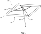
FIG. 1 is a bottom perspective view of an umbrella including a pole assembly, a shade member, an upper hub, and a lower hub; -
FIG. 2 is a plane view of the umbrella ofFIG. 1 with the shade member removed showing the shade assembly and the pole assembly; -
FIG. 3 is a top perspective view of the umbrella ofFIG. 1 illustrating one embodiment of a lower hub including hooks pivotally connected to an upper fixture coupled with the pole assembly, two struts having been removed to show the hub structure more clearly; -
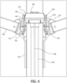
FIG. 4 is another view of the umbrella ofFIG. 1 showing the hooks of the lower hub engaged with a ledge of the upper fixture; -
FIG. 5A is an exploded view of the lower hub and upper fixture of the portion of the umbrella ofFIG. 1 shown inFIG. 3 ; -
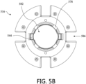
FIG. 5B is a top view of the lower hub of the umbrella ofFIG. 1 , the lower hub including alignment recesses; -
FIG. 5C is a bottom view of the upper fixture of the umbrella ofFIG. 1 , the upper fixture including alignment tabs; -
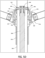
FIG. 5D shows a cross-section of the lower hub and handle, with the handle in a second position to disengage hooks from ledges of the upper fixture; -
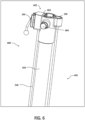
FIG. 6 is a top perspective view of an upper portion of a lift assembly that includes a hollow tube coupled to an inner fixture and a cord disposed over a pulley at one end and coupled to the inner fixture at another end; -
FIG. 7 is a side view of a lower portion of the lift assembly ofFIG. 6 showing a piston coupled to the hollow tube at one end and coupled to a lower fixture at another end; -
FIG. 8 is a bottom perspective view of the lift assembly ofFIGS. 6 and7 showing the piston extending to within the hollow tube and a seal disposed between the piston and the hollow tube; -
FIG. 9 is a cross-section view of the lower fixture of the lower portion of the lift assembly shown inFIG. 7 , the lower fixture supporting a pulley, the cord positioned over the lower side of pulley; -
FIG. 10 shows the lower fixture ofFIG. 9 with the piston coupled thereto and the cord positioned within cord openings thereof; -
FIG. 11 shows the lower fixture ofFIG. 10 with the lower end of the piston and the cord removed, better illustrating a piston opening, the cord openings, and spacers; -
FIG. 12 shows a perspective view of a design of an umbrella hub and a handle; -
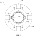
FIG. 13 shows a top view of the umbrella hub and handle design ofFIG. 12 ; -
FIG. 14 shows a bottom view of the umbrella hub and handle design ofFIG. 12 ; -
FIGS. 15-16 show side views of the umbrella hub and handle design ofFIG. 12 with the handle in a first position; and -
FIG. 17 shows a side view of the umbrella hub and handle design ofFIG. 12 with the handle in a second position. - This application is directed to new umbrella assemblies that assist a user in actuating the umbrella, e.g., by providing an upward or downward directed force to reduce the amount of force needed in one or both of opening and closing the umbrella. In one embodiment, a gas spring is provided. The gas spring can be configured to provide an assist in the lifting of a lower hub of the umbrella, sometimes referred to herein as a lifter assist. Such assist is particularly useful in the opening of large umbrellas. These assemblies can be embodied in or operate with novel hub configurations and designs. A lift assembly with a hollow tube, a piston disposed at least partially within the hollow tube, a seal, and a cord facilitate movement of the lower hub when opening the umbrella as discussed in greater detail below. The gas spring can alternatively be used to assist in the closing of or in maintaining an umbrella closed.
-
FIGS. 1 and2 show anumbrella 500 including a hollow pole assembly 504 (also sometimes referred to herein as a hollow pole) and ashade assembly 502 having anupper hub 512, alower hub 516, and ashade structure 509. Theshade structure 509 can connect thelower hub 516 and theupper hub 512. Theshade structure 509 can includeribs 524, struts 520. The shade assembly can include theshade structure 509 and ashade member 508. Theribs 524 are coupled at one end to theupper hub 512. Theribs 524 are coupled at a location along their length to one end of the corresponding struts 520. The end of thestruts 520 that are not coupled to theribs 524 are coupled to thelower hub 516. Theumbrella 500 can be opened and closed by moving thelower hub 516 along thehollow pole assembly 504. Thelower hub 516 can be moved in the upward direction to open theumbrella 500 and moved in the downward direction to close theumbrella 500. Theumbrella 500 can include astrap 528 in one example to assist in keeping theumbrella 500 closed. A lower end of thehollow pole assembly 504 can be inserted into a weighted base or a fixture secured to or embedded in a ground surface. -
FIGS. 3 and4 show an embodiment of thelower hub 516, anupper fixture 532, and ahandle 556. Thelower hub 516 can be disposed on the outside of thehollow pole assembly 504. Thehollow pole assembly 504 can be disposed through an opening in thelower hub 516 that is sized to allow sliding over the outer surface of the pole. Theupper fixture 532 can be disposed on the outside of thehollow pole assembly 504 and above thelower hub 516. Thehandle 556 can be disposed on the outside of thehollow pole assembly 504 and below thelower hub 516. Thehandle 556 can have an upper portion positioned in arecess 545 of thelower hub 516. When thehandle 556 is pulled down, the handle can create a separation between the upper portion of thehandle 556 and an internal aspect of therecess 545 of thelower hub 516. - The
lower hub 516 can be secured to thehollow pole assembly 504 via theupper fixture 532. Thelower hub 516 can include at least onehook 544. Movement of thehandle 556 relative to thelower hub 516 of alower hub assembly 515 of which thehandle 556 and thelower hub 516 are a part can actuate thehook 544 or another form of locking mechanism to allow for collapsing theumbrella 500. Theupper fixture 532 can include at least oneledge 540. Thelower hub 516 can include a plurality ofhooks 544. Theupper fixture 532 can include a plurality ofledges 540. The number ofhooks 544 can correspond to the number ofledges 540. Thehook 544 can be pivotally connected to thelower hub 516 via apin 552. When theumbrella 500 is opened, thehook 544 can rest on thecorresponding ledge 540 to help retain theumbrella 500 in an open state. When theumbrella 500 is to be closed, thehook 544 can be disengaged or pivoted away from theledge 540 to allow thelower hub 516 to move downward along thehollow pole assembly 504 and theumbrella 500. The downward movement of thelower hub 516 allows theumbrella 500 to close. The pulling of thehandle 556 can cause thehook 544 to disengage or pivot away from theledge 540, as discussed further below. -
FIGS. 3 and4 also show acord 548, discussed in more detail below. Thecord 548 can assist in the opening and closing of theumbrella 500. Afirst end 549 of thecord 548 can be coupled with thehollow pole assembly 504 directly or indirectly, e.g., by way of aninner fixture 602.FIG. 3 shows that theinner fixture 602 can be mounted in an inside area of thehollow pole assembly 504.FIG. 6 shows thatinner fixture 602 can have a number of protrusions that extend radially outward to free ends that can be in disposed adjacent to or in contact with interior walls of thehollow pole assembly 504. As discussed further below, one of the protrusions of theinner fixture 602 can include anopening 598 for securing the first end of thecord 548. Asecond end 550 of thecord 548 can be coupled with thelower hub 516, as described in more detail herein. When closing theumbrella 500, thelower hub 516 can be moved downward along thehollow pole assembly 504. As thelower hub 516 moves downward a span or length of thecord 548 can pass over apulley 594 coupled with another protrusion of theinner fixture 602. The movement of the span or length of thecord 548 over thepulley 594 can apply a load to compress agas lifter 601 as discussed in further detail below. Thegas lifter 601 is sometimes referred to herein as a gas spring. -
FIG. 5A shows an exploded view of thelower hub 516 and theupperfixture 532. Theupper fixture 532 can be sized to fit at least partially within thelower hub 516. Theouter perimeter 590 of theupper fixture 532 can be sized to fit within theopening 582 of thelower hub 516. In some embodiments, theupper fixture 532 can have at least oneradial projection 574. Any number ofradial projections 574 can be used. For example, one, two, three, four or moreradial projections 574 can be provided. Thelower hub 516 can have at least oneradial recess 578. The number ofradial recesses 578 can correspond to the number ofradial projections 574. Theradial projections 574 can be positioned and/or aligned with theradial recesses 578 when positioning theupperfixture 532 within theopening 582 of thelower hub 516. The radial projection(s) 574 can be sized to fit within the radial recess(es) 578. The circumferential extent of the radial projection(s) 574 can be less than the circumferential extent of the radial recess(es) 578. Theupper fixture 532 can remain fixed in its position on thehollow pole assembly 504 while thelower hub 516 moves along thehollow pole assembly 504 to open and close theumbrella 500. Also, theupper fixture 532 can have one or a plurality ofradial recesses 578A and thelower hub 516 can have one or a plurality ofradial projection 574A. The radial projection(s) 574A can be received within the radial recess(es) 578A. The radial projection(s) 574 and radial recess(es) 578 and/or the radial projection(s) 574A and the radial recess(es) 578A to reduce, restrict or eliminate rotational movement of thelower hub 516 relative to thehollow pole assembly 504. - The
upper fixture 532 can include at least oneledge 540, as discussed herein. Theupper fixture 532 can have one, two, three ormore ledges 540. The at least oneledge 540 can interact with the at least onehook 544 of thelower hub 516, as described herein. There can be a corresponding number ofledges 540 and hooks 544. Theledge 540 can be disposed on opposite sides of theupper fixture 532, e.g., can be disposed on a common diameter of theupper fixture 532. - The
upper fixture 532 can have aslot 564. Theslot 564 can allow thecord 548 to exit the interior space of thehollow pole assembly 504 to be coupled to thelower hub 516 as described herein. Theslot 564 can be sized to allow a portion of thepulley 594 to extend at least partially into and through a wall of theupper fixture 532. In one embodiment an assembly including thepulley 594 can be partially or completely mounted to theupper fixture 532. - The
lower hub 516 can have at least onestrut recess 586. The struts (e.g., struts 520) can be coupled to thelower hub 516 by being positioned within the corresponding strut recesses 586. Pins or other pivot members (not shown) can be used to secure thestruts 520 in place. The number ofstruts 520 can be equal to the number of strut recesses 586 in various embodiments of theumbrella 500. -
FIG. 5B shows a top view of thelower hub 516. As described above, thelower hub 516 can include hooks 544. In some embodiments, thelower hub 516 can have twohooks 544. Thehooks 544 can be positioned opposite each other, e.g., symmetrically about a common diameter extending across thelower hub 516. In some embodiments, the hooks 544 (e.g., two, three, four, or more hooks 544) can be spaced equally around theopening 582 of thelower hub 516. In some embodiments, thehooks 544 can be spaced at unequal distances around theopening 548. Thelower hub 516 can haveradial recesses 578 for maintaining alignment with theupper fixture 532 as described in more detail above. The lower hub can havestrut recesses 586 as described in more detail above. -
FIG. 5C shows a bottom view of theupper fixture 532. As described above, theupper fixture 532 can includeradial projections 574. Theradial projections 574 can protrude outward from a bottom surface of theupper fixture 532. Theradial projection 574 can extend between a smaller diameter of the bottom surface and anouter perimeter 590 of theupper fixture 532. In some cases, theouter perimeter 590 has a larger diameter than the outer diameter of the bottom surface of theupper fixture 532. Theradial projections 574 can be configured to interact with theradial recesses 578 as described above. Theupper fixture 532 can have aslot 564. Theslot 564 can allow thecord 548 to exit the interior space of thehollow pole assembly 504 to be coupled to thelower hub 516 as described herein. With reference, toFIG. 6 , thecord 548 can be disposed overpulley 594. Thecord 548 can then exit through theslot 564 to couple to thelower hub 516. -
FIG. 5D shows a cross-section of thelower hub 516 and thehandle 556. Thehandle 556 is in a position to disengage thehooks 544 from theledges 540 of theupper fixture 532. Thehandle 556 can be pulled down along thehollow pole assembly 504. When thehandle 556 is pulled down, the handle can create a separation between the upper portion of thehandle 556 and an internal or lower aspect of therecess 545 of thelower hub 516. The movement of thehandle 556 can disengage aprong 541 of thehooks 544 from theledges 540. Thehooks 554 can pivot away from the correspondingledges 540 allowing thelower hub 516 to move downward along thehollow pole assembly 504. Thehooks 544 can have a curvedlower portion 546 that can be moved inward toward thehollow pole assembly 504 within a gap orspace 547 when thehandle 556 is pulled down. The curvedlower portion 546 can move radially inward within the gap orspace 547 to allow thehook 544 to pivot away from the correspondingledge 540, which in turn can allow thelower hub 516 to move downward along thehollow pole assembly 504. An upper structure of thehandle 556, such as a roller or projections, can rest on or just above the curved portion of thehook 544 such that as thehandle 556 moves down the upper structure applies a load to the curved portion. When closing theumbrella 500, the upper portion of thehook 544 can move further away from thehollow pole assembly 504, while the curvedlower portion 546 can move closer to thehollow pole assembly 504 by radially inward load applied by the roller or projection of the upper structure. The distance the upper portion of thehook 544 can move away from thehollow pole assembly 504 can be limited by aninterior wall 554 of thelower hub 516. The limited movement can allow for a more controlled locking and unlocking process. -
FIGS. 6-8 show alift assembly 600. Thelift assembly 600 can be disposed within thehollow pole assembly 504. Thelift assembly 600 can include agas lifter 601. Thegas lifter 601 is sometimes referred to herein as a gas spring. As discussed further below, thegas lifter 601 is a device that stores potential energy in a compressed gas and then releases that energy to apply a load as needed. In some embodiments, thegas lifter 601 can include thehollow tube 560 having an open interior. Thegas lifter 601 can include apiston 610. The outer diameter of thepiston 610 can be sized to fit within the inner diameter of thehollow tube 560. Thegas lifter 601 can include aseal 622. Theseal 622 can be positioned between the inner diameter of thehollow tube 560 and outer diameter of thepiston 610, as shown inFIG. 8 . - As shown in
FIG. 6 , thehollow tube 560 can be coupled toinner fixture 602. Theinner fixture 602 can be coupled to thehollow pole assembly 504. In some embodiments, theinner fixture 602 can be coupled to theupper fixture 532. Theinner fixture 602 can haveprotrusions 603. Two or more of theprotrusions 603 can be coupled to thehollow pole assembly 504 or theupper fixture 532. Theinner fixture 602 can have two, three, four ormore protrusions 603 to fix theinner fixture 602 with thehollow pole assembly 504. Theprotrusions 603 can have anextender 604. Theextender 604 can have a narrower diameter or cross-section than theprotrusion 603. Theextender 604 can assist in coupling theinner fixture 602 to thehollow pole assembly 504 or theupper fixture 532. Theextender 604 can include a rivet, a screw or a bolt to secure theupper fixture 532 to thehollow pole assembly 504.FIG. 5D shows that thehollow tube 560 can be fixed to thehollow pole assembly 504 by theinner fixture 602 and theextender 604. The movement of thegas lifter 601 is by way of thepiston 610 from below the position of the upper portion of thehollow tube 560 which is secured to thehollow pole assembly 504 by theextender 604. The lower end of thepiston 610 moves downward as stored energy is released, as discussed further below. This allows thepiston 610 to move over a distance that can be any distanced from the location of the lower end of thehollow tube 560 to the lower end of thehollow pole assembly 504. Also, the free end of thepiston 610 is not directly connected to a hub. Thus, the movement of the free end is not limited by an amount of movement of a hub, but rather can be adjusted as needed. In examples disclosed herein, this allows theumbrella 500 to be designed with just two hubs, e.g., theupper hub 512 and thelower hub 516. Also, the free end of thepiston 610 of thegas lifter 601 can be disposed outside of the expanse of theumbrella 500 that is between theupper hub 512 and thelower hub 516, e.g., below thelower hub 516. By providing for umbrella assist operation using thegas lifter 601 without locating the free end of thepiston 610 between or within the hubs, theumbrella 500 can be constructed without any intermediate struts coupled with intermediate hubs. This approach simplifies the design by eliminating unnecessary pivotable connections between shorter struts. - The
cord 548 can be positioned over thepulley 594 and extend down the length of thehollow tube 560. Thecord 548 can extend through an opening of afirst projection 618 of acord guide member 614. Thecord guide member 614 can be disposed around thehollow tube 560. Theprojections 618 of thecord guide member 614 can be positioned around thecord guide member 614 separated at equal or unequal distances. Thecord guide member 614 can have at least twoprojections 618. Thecord 548 can continue to extend down along the length ofpiston 610, as shown inFIGS. 7 and8 . Thecord 548 can extend into and out alower fixture 606, as discussed in more detail below. Thecord 548 can then extend back up the length ofpiston 610, through a second opening of asecond projection 618 of thecord guide member 614, up the length of thehollow tube 560 and be coupled at anopening 598 of theinner fixture 602. - The
member 614 serves a spacing function theumbrella 500 in some examples. Themember 614 comprise a centering member such that it is disposed centrally in the interior space of thehollow pole assembly 504. Theprojections 618 can extend substantially equal amounts from acentral hub 615 of themember 614. Theprojection 618 can have an arcuate outer periphery to contact an inner diameter of thehollow pole assembly 504. In one embodiment, an outer surface of theprojection 618 has a radius that is smaller than the radius of thehollow pole assembly 504 such that the contact between themember 614 and the inner surface of thehollow pole assembly 504 can be tangential or along a short arc of the inner surface of thehollow pole assembly 504. Themember 614 is coupled with a bottom end of thehollow tube 560 and can be used to position thehollow tube 560 generally centrally within thehollow pole assembly 504, e.g., by placing each of two, three, four, ormore projection 618 in contact with the inner surface of thehollow pole assembly 504. As discussed above, thecord guide member 614 may also have one or more openings to allow thecord 548 to pass through. In other embodiments, thecord 548 is allowed to pass between the member 614 (serving to center the hollow tube 560) and the inner surface of thehollow pole assembly 504 but not through any portion of themember 614. - When closing the
umbrella 500, thecord 548 can apply a load to compress thegas lifter 601. In some embodiments, thepiston 610 can be moved at least partially into or deeper into thehollow tube 560 to compress air or another gas within thehollow tube 560. When opening theumbrella 500, thegas lifter 601 can apply a load to thecord 548 to cause thelower hub 516 to be moved upward and open theumbrella 500. - When the
umbrella 500 is open, the length of thecord 548 between thefirst end 549 and thelower fixture 606 and the length of thecord 548 between thesecond end 550 and thelower fixture 606 can be similar, e.g., substantially equal. When theumbrella 500 is closed, the length of thecord 548 between thefirst end 549 and thelower fixture 606 can be greater than the length of thecord 548 between thefirst end 549 and thelower fixture 606 when the umbrella is opened. When theumbrella 500 is closed, the length of thecord 548 between thesecond end 550 and thelower fixture 606 can be greater than the length of thecord 548 between thesecond end 550 and thelower fixture 606 when the umbrella is opened. When theumbrella 500 is closed, the length of thecord 548 between thefirst end 549 and thelower fixture 606 can be greater than the length of thecord 548 between thesecond end 550 and thelower fixture 606. The length of thecord 548 between thefirst end 549 and thelower fixture 606 can increase as thelower hub 516 is moved downward along thehollow pole assembly 504. The length of thecord 548 between thefirst end 549 and thelower fixture 606 can decrease as thelower hub 516 is moved upward along thehollow pole assembly 504. The length of thecord 548 between thesecond end 550 and thelower fixture 606 can increase as thelower hub 516 is moved downward along thehollow pole assembly 504. The length of thecord 548 between thesecond end 550 and thelower fixture 606 can decrease as thelower hub 516 is moved upward along thehollow pole assembly 504. -
FIG. 9 shows a cross section view of an example of thelower fixture 606. Thelower fixture 606 can be coupled to thepiston 610. Thepiston 610 can be sized to fit within anopening 638 of a core member orcentral hub 642 in thelower fixture 606. In some embodiments, thepiston 610 can be coupled tolower fixture 606 by a pin, a rivet, a screw, a bolt, orother shaft member 607. Any suitable means can be used to couple thepiston 610 to thelower fixture 606. Thecord 548 can extend within thelower fixture 606 and be disposed around apulley 626. Thepulley 626 can be supported on thecore member 642 by anaxle 627. Theaxle 627 can comprise a smooth, round central portion of a rivet, screw, bolt or other member mounted across thelower fixture 606. Thecord 548 can enter a first cord opening 634 of thelower fixture 606. The cord can then extend around thepulley 626 and exit a second cord opening 634 of thelower fixture 606. A span of thecord 548 over thepulley 626 can be disposed above a lower end of thelower fixture 606 to protect thecord 548 from contact as it moves over thepulley 626. -
FIG. 10 shows another view of thelower fixture 606. As shown and described herein, thelower fixture 606 can includecord openings 634 for thecord 548 to enter through before being disposed over apulley 626. Thelower fixture 606 can be coupled to thepiston 610 as described herein. -
FIG. 11 shows an example embodiment of thelower fixture 606 havingspacers 630 andcord openings 634. Any number ofspacers 630 can be used. For example, one, two, three, four ormore spacers 630. Thespacers 630 can extend the entire length of thelower fixture 606. In some embodiments, thespacers 630 can extend a portion of the length of thelower fixture 606. Thespacers 630 can be spaced equally around theopening 638 and thecore member 642. In some embodiments, thespacers 630 can be spaced at unequal distances around theopening 638. Thespacers 630 can extend outward from thecore member 642. Thespacers 630 can haveouter edges 646. Thespacers 630 can have a plate-like configuration, e.g., being elongate in a vertical direction and having rectangular side surfaces with relatively thin circumferential thickness. Theouter edges 646 of thespacers 630 can assist in maintaining the alignment of thelift assembly 600 when moving within thehollow pole assembly 504 by engaging the inner wall of thehollow pole assembly 504. The thin contact between thespacers 630 and the inner walls of thehollow pole assembly 504 provide for minimal sliding friction. - The
cord openings 634 can be sized to allow thecord 548 to fit within thecord openings 634. Thecord openings 634 can be positioned on opposite sides of thelower fixture 606. In some embodiments, each cord opening 634 can be positioned between twospacers 630. The cord openings can extend down at least a portion of the length of thelower fixture 606. As described herein, thecord 548 can enter afirst cord opening 634 and then be disposed around apulley 626 and then exit asecond cord opening 634. -
FIGS. 12-17 show a design of anumbrella hub 515.FIG. 12 shows a perspective view of a design of anumbrella hub 515 with alower hub 516, ahandle 556, and hooks 544. Thelower hub 516 can be located above thehandle 556. An upper portion of thehandle 556 can be positioned in arecess 545 of thelower hub 516. Thehooks 544 can extend above the upper surface of thelower hub 516. Thelower hub 516 can include strut recesses 586. -
FIG. 13 shows a top view of theumbrella hub 515. Thelower hub 516 is shown as having four strut recesses 586. The strut recesses 586 can be evenly spaced around the circumference of thelower hub 516. Thehooks 544 can be positioned across from each other within an inner diameter of thelower hub 516.FIG. 14 shows a bottom view of theumbrella hub 515. As shown, the upper portion of thehandle 556 can taper inward towards the base of thehandle 556. -
FIGS. 15-16 show side views of theumbrella hub 515 in a first configuration. As described herein, thehandle 556 is positioned within therecess 545 of thelower hub 516. Thehooks 544 can align with two of the strut recesses 586.FIG. 16 shows that thehooks 544 can be substantially parallel to a longitudinal access extending through the center of theumbrella hub 515. -
FIG. 17 shows a side view of theumbrella hub 515 in a second configuration. Thehandle 556 is positioned downward compared to the position inFIG. 16 and partially out of therecess 545 of thelower hub 516. Thehooks 544 have pivoted away from the longitudinal access extending through the center of theumbrella hub 515.
Claims (15)
- An umbrella (500) comprising:a hollow pole (504);a shade assembly (502) coupled with an upper portion of the hollow pole (504), the shade assembly (502) comprising:an upper hub (512), a lower hub (516), a shade structure (509) coupling the upper hub (512) to the lower hub (516), the shade structure (509) supporting a shade member (508), wherein the lower hub (516) is moveable along the hollow pole (504);a lift assist assembly (600) disposed within the hollow pole (504), the lift assist assembly (600) comprising a gas spring (601) and a cord (548) having a first end coupled with the hollow pole (504) and a second end coupled with the lower hub (516); wherein when closing the umbrella (500), the cord (548) applies a load to compress the gas spring (601) and when opening the gas spring (601) applies a load to the lower hub (516) by way of the cord (548).
- The umbrella of Claim 1 further comprising a hook (544) pivotably mounted in the lower hub (516), the hook (544) configured to rest on a ledge (540) of the hollow pole (504) when the umbrella (500) is open and to pivot away from the ledge (540) to allow the umbrella (500) to be closed, the pivoting of the hook (544) being actuated by downward movement of a handle (556) relative to an upper portion of the lower hub (516).
- The umbrella of claim 2, wherein the handle (556) extends downward from a lower portion of the lower hub (516), the handle (556) being moveable downward relative to an upper portion of the lower hub (516) when the hook (544) is resting on the ledge (540) to pivot the hook (544) away from the ledge (540) to allow the lower hub (516) to be lowered to allow the umbrella (500) to collapse.
- The umbrella of Claim 3, wherein the hook (544) comprises a curved lower portion (546) that is actuated by movement of a roller disposed in the handle (556).
- The umbrella of claim 1, wherein the cord (548) is disposed over a pulley (594) coupled with the hollow pole (504) and is tension by downward movement of the lower end of the gas spring (601) and/or downward movement of the lower hub (516).
- The umbrella of Claim 1, wherein downward movement of the lower hub (516) raises a lower end of the gas spring (601) to compress the gas spring (601).
- The umbrella of Claim 1, further comprising an upper fixture (532) disposed on the hollow pole (504), the upper fixture (532) comprising a pulley (594) and at least one ledge (540) for a corresponding hook (544) of the lower hub (516) to interact with.
- The umbrella of Claim 1, wherein the gas spring (601) further comprising a lower fixture (606) comprising a central hub (642) and a plurality of spacers (630), each spacer (630) extending from the central hub (642) to a free end.
- The umbrella of Claim 1, wherein the lower fixture (606) comprises a pulley (626), the cord (548) being disposed around the pulley (626).
- The umbrella of Claim 1, further comprising a strap (528) to retain the umbrella (500) in a closed state.
- The umbrella of Claim 1, wherein the gas spring (601) further comprises a hollow tube (560) and a piston (610) sized to fit within the hollow tube (560).
- The umbrella of Claim 11, wherein the gas spring (601) further comprising a seal (622) positioned between an inner diameter of the hollow tube (560) and the outer diameter of the piston (610).
- The umbrella of Claim 1, further comprising an upper fixture (532) disposed on the hollow pole (504), the upper fixture (532) comprising a radial projection (574) disposed on a lower portion, the lower hub (516) comprising a radial recess (578) disposed on an inner periphery of an upper portion, the radial projection (574) configured to be disposed in the radial recess (578) to limit rotation of the lower hub (516) about the hollow pole (504).
- The umbrella of Claim 13, wherein the upper fixture (532) comprises a plurality of radial projections (574) disposed on a lower portion, the lower hub (516) comprising a plurality of radial recess (578) disposed on an inner periphery of an upper portion, the radial projections (574) configured to be disposed in the radial recesses (578) to limit rotation of the lower hub (516) about the hollow pole (504).
- The umbrella of Claim 1, further comprising a cord guide member (614) disposed about a hollow tube (560) of a gas spring (601) of the lift assist assembly (600), the cord guide member (614) comprising a plurality of projections (618) configured to slide along the inner surface of the hollow pole (504).
Applications Claiming Priority (1)
| Application Number | Priority Date | Filing Date | Title |
|---|---|---|---|
| US202163264026P | 2021-11-12 | 2021-11-12 |
Publications (3)
| Publication Number | Publication Date |
|---|---|
| EP4179915A1 true EP4179915A1 (en) | 2023-05-17 |
| EP4179915C0 EP4179915C0 (en) | 2024-09-25 |
| EP4179915B1 EP4179915B1 (en) | 2024-09-25 |
Family
ID=81454797
Family Applications (1)
| Application Number | Title | Priority Date | Filing Date |
|---|---|---|---|
| EP22020198.2A Active EP4179915B1 (en) | 2021-11-12 | 2022-04-30 | Umbrella assembly with gas spring |
Country Status (2)
| Country | Link |
|---|---|
| US (2) | US12507772B2 (en) |
| EP (1) | EP4179915B1 (en) |
Families Citing this family (5)
| Publication number | Priority date | Publication date | Assignee | Title |
|---|---|---|---|---|
| US12317977B2 (en) | 2019-03-21 | 2025-06-03 | ZHUN-AN Ma | Tilt mechanisms and actuators for umbrellas |
| CN113331559A (en) | 2020-10-26 | 2021-09-03 | 青岛万汇遮阳用品有限公司 | Umbrella with hub reinforced inclined joint |
| EP4118998B1 (en) | 2021-07-13 | 2023-12-27 | Activa Leisure Inc. | Umbrella assembly with counterweight system |
| US12207714B2 (en) | 2021-08-11 | 2025-01-28 | ZHUN-AN Ma | Umbrella pole |
| USD1100481S1 (en) * | 2024-08-23 | 2025-11-04 | Aftercloud Technology Co., Ltd. | Patio umbrella |
Citations (3)
| Publication number | Priority date | Publication date | Assignee | Title |
|---|---|---|---|---|
| US3683948A (en) * | 1971-04-09 | 1972-08-15 | Paul J Cohen | Umbrella of collapsible construction |
| US4807655A (en) * | 1985-05-03 | 1989-02-28 | Robertson Malcolm S | Garden or sun umbrellas |
| US9004087B2 (en) * | 2011-04-12 | 2015-04-14 | Zhunan Ma | Controllable automatic umbrella unfolding device |
Family Cites Families (305)
| Publication number | Priority date | Publication date | Assignee | Title |
|---|---|---|---|---|
| US593726A (en) | 1897-11-16 | Mark m | ||
| US680661A (en) * | 1901-01-18 | 1901-08-13 | Joseph P Cleal | Self-opening umbrella. |
| US835306A (en) | 1905-09-26 | 1906-11-06 | Gustav A Mangelsdorf | Umbrella. |
| US878270A (en) | 1907-07-29 | 1908-02-04 | Franz Binninger | Umbrella or parasol frame. |
| US957528A (en) | 1909-09-01 | 1910-05-10 | Zittlosen Mfg Company | Hinge-joint. |
| US956657A (en) | 1909-09-01 | 1910-05-03 | Zittlosen Mfg Company | Umbrella-runner. |
| US1136887A (en) | 1914-06-03 | 1915-04-20 | William Sylvester Penn | Umbrella-frame. |
| US1268354A (en) | 1914-09-28 | 1918-06-04 | Frank W Howard | Umbrella-runner. |
| US1243594A (en) | 1915-11-06 | 1917-10-16 | Troy Carriage Sun Slade Company | Umbrella-runner. |
| US1235296A (en) | 1915-11-06 | 1917-07-31 | Troy Carriage Sun Shade Company | Umbrella top-notcher. |
| US1255627A (en) | 1916-06-22 | 1918-02-05 | John B Morrow | Umbrella. |
| US1801913A (en) | 1930-03-01 | 1931-04-21 | Clifford W Frederick | Tent frame |
| AT128258B (en) | 1931-03-14 | 1932-05-25 | Josef Fiehl Recte Deile | Device for tilting the canopy of parasols. |
| US1881990A (en) | 1931-07-21 | 1932-10-11 | Fretz Gross & Co | Tilting device for umbrellas |
| US2013192A (en) | 1932-11-23 | 1935-09-03 | Smith Thomas Sidney | Joint fitting for sun umbbella poles |
| US1972653A (en) | 1933-09-23 | 1934-09-04 | Alfred V Hart | Handle for sweeps and the like |
| US2223253A (en) | 1939-08-30 | 1940-11-26 | James H Hamilton | Umbrella support |
| US2341399A (en) | 1941-02-27 | 1944-02-08 | William S Timblin | Umbrella, and method of and apparatus for manufacturing same |
| US2447972A (en) | 1947-04-07 | 1948-08-24 | Fed Lab Inc | Target balloon |
| US2462560A (en) | 1947-10-28 | 1949-02-22 | Schmidt Edward | Tiltable umbrella |
| US2475406A (en) | 1947-12-26 | 1949-07-05 | Ray A Russell | Remote-control counterbalance tilting joint for umbrellas |
| US2719688A (en) | 1949-11-21 | 1955-10-04 | Seifert Karl | Telescopic tubes |
| US2661012A (en) | 1950-11-14 | 1953-12-01 | Finkel Umbrella Frame Company | Tiltable umbrella |
| US2745421A (en) | 1953-04-16 | 1956-05-15 | Ray A Russell | Umbrella latch and runner combination |
| US2762383A (en) | 1953-09-22 | 1956-09-11 | Norman M Wittman | Means for securing umbrella ribs |
| US2721569A (en) | 1954-08-13 | 1955-10-25 | Finkel Umbrella Frame Company | Tiltable garden umbrella |
| USRE24477E (en) * | 1955-03-14 | 1958-05-27 | Beach and garden umbrella and mechanism for | |
| US2819725A (en) | 1956-03-19 | 1958-01-14 | Troy Sunshade Company | Umbrella |
| US2937653A (en) | 1957-03-04 | 1960-05-24 | Calpatio Co Inc | Supporting and release catch for umbrella runners |
| US2932047A (en) | 1958-04-21 | 1960-04-12 | John M Johnston | Extensible mop handle |
| CH367290A (en) | 1959-03-08 | 1963-02-15 | Glatz Albert | Garden umbrella |
| US3142307A (en) | 1960-08-09 | 1964-07-28 | Calpatio Co | Tilting umbrella assembly |
| US3175568A (en) | 1961-07-18 | 1965-03-30 | Kafka Jack | Tiltable umbrella construction |
| US3129715A (en) | 1961-08-15 | 1964-04-21 | Finkel Outdoor Prod | Motor driven winding mechanism |
| US3177882A (en) | 1962-01-08 | 1965-04-13 | Finkel Umbrella Frame Company | Plastic umbrella frames |
| US3177883A (en) | 1962-01-08 | 1965-04-13 | Finkel Umbrella Frame Company | Unitary umbrella frames |
| US3171418A (en) | 1963-03-26 | 1965-03-02 | Meyer Siegfried | Collapsible umbrella |
| US3145720A (en) | 1962-11-29 | 1964-08-25 | Torii Giichi | Canopy tilting device |
| US3279835A (en) | 1964-02-12 | 1966-10-18 | Anderson Co | Adapter |
| US3311119A (en) | 1965-04-22 | 1967-03-28 | Pearlstine Morton | Automatically tiltable beach umbrella |
| US3424180A (en) | 1965-04-29 | 1969-01-28 | Giancarlo Andolfi | Framework of plastic material for umbrella,beach sunshade or parasols |
| US3253310A (en) | 1965-05-04 | 1966-05-31 | Norco Inc | Releasable two-part fastener |
| US3347575A (en) | 1965-09-07 | 1967-10-17 | Morris Mfg Company | Detent guide for telescopic tube units |
| DE1248246B (en) | 1966-04-28 | 1967-08-24 | Bremshey & Co | Shortened umbrella |
| NL6705714A (en) | 1966-08-12 | 1968-02-13 | ||
| US3521651A (en) | 1968-07-09 | 1970-07-28 | Morton Pearlstine | Tiltable beach umbrella |
| DE2226384C3 (en) | 1972-05-31 | 1979-08-30 | Bremshey Ag, 5650 Solingen | Screen slide |
| US3802452A (en) | 1972-08-07 | 1974-04-09 | Telesco Brophey Ltd | Collapsible umbrella |
| FR2238449A1 (en) | 1973-07-25 | 1975-02-21 | Sauvagnat & Cie | Motor driven sun blind tilting mechanism - screw and nut move crank to tilt blind support |
| SE410389B (en) * | 1978-01-12 | 1979-10-15 | Avraham Cohen | STEPLESS LENGTH ADJUSTABLE CRUCK |
| US4368749A (en) | 1978-12-22 | 1983-01-18 | The Shakespeare Company | Wireless umbrella frame |
| USD265498S (en) | 1980-10-20 | 1982-07-20 | American Standard Inc. | Combined spout and water control handles |
| US4385849A (en) | 1981-02-02 | 1983-05-31 | Crain Enterprises, Inc. | Extensible and retractable rod |
| JPS58107024A (en) | 1981-12-17 | 1983-06-25 | 株式会社東芝 | Electric power supply device |
| USD276838S (en) | 1982-08-26 | 1984-12-18 | Masco Corporation Of Indiana | Faucet handle design |
| CH661189A5 (en) | 1983-09-08 | 1987-07-15 | Glatz Ag | LARGE SCREEN. |
| JPS6137814A (en) | 1984-07-31 | 1986-02-22 | Daicel Chem Ind Ltd | Production of lactone-grafted cellulose derivative |
| CH666166A5 (en) | 1984-09-07 | 1988-07-15 | Glatz Ag | HANGING UMBRELLA. |
| US4622987A (en) | 1985-06-13 | 1986-11-18 | Finkel Outdoor Products, Inc. | Rotatable shade umbrella |
| US4829857A (en) | 1987-02-25 | 1989-05-16 | Jones Arlan N | Quick change handle for tools |
| GB2202141B (en) | 1987-03-18 | 1991-01-23 | Kortenbach Verwaltung | Tilting mechanism in standing umbrella frame |
| US4811670A (en) | 1987-07-24 | 1989-03-14 | Intermetro Industries Corporation | Shelf support system having a triangular support post |
| US4911573A (en) | 1987-12-24 | 1990-03-27 | Nuova Omec S.R.L. | Rigid axial retainer |
| CH675956A5 (en) | 1988-02-11 | 1990-11-30 | Markus Stromeyer | |
| US4928718A (en) * | 1988-08-08 | 1990-05-29 | American Holtzkraft, Inc. | Umbrella |
| CH676539A5 (en) | 1988-12-22 | 1991-02-15 | Stromeyer & Co Gmbh L | |
| US4878509A (en) | 1989-05-10 | 1989-11-07 | Tung L | Stepless tilting device for umbrella |
| DE8909209U1 (en) | 1989-07-29 | 1990-11-29 | Aug. Grönlinger Nachf. GmbH & Co KG, 5600 Wuppertal | Umbrella, especially umbrella |
| US5020557A (en) | 1990-07-19 | 1991-06-04 | American Holtzkraft, Inc. | Rotating canopy umbrella |
| US4993445A (en) | 1990-08-16 | 1991-02-19 | Emanuel Dubinsky | Garden umbrella with solid wooden pole designed to operate with hand crank and pulley system |
| US5029596A (en) | 1990-08-31 | 1991-07-09 | Tung L | Stepless tilting device for umbrella |
| IT1247074B (en) | 1991-02-20 | 1994-12-12 | S M I T Stampi Minuterie Tranc | CANNOLINO WITH AUTOMATIC RELEASE OF THE SPRING FOR UMBRELLAS OR SIMILAR. |
| US5307827A (en) | 1991-07-22 | 1994-05-03 | Haddad Joseph F | Umbrella |
| USD344786S (en) | 1992-03-06 | 1994-03-01 | Sterling Plumbing Group, Inc. | Plumbing fitting handle |
| US5174319A (en) | 1992-06-17 | 1992-12-29 | Dat, Sheng-Tong | Longer effective automatic umbrella |
| US5186197A (en) | 1992-07-06 | 1993-02-16 | Lavine Edward L | Collapsible umbrella handle |
| US5284171A (en) | 1992-12-07 | 1994-02-08 | Liu Chin Hsiang | Sunshade opening and supporting device |
| US5333824A (en) | 1993-05-04 | 1994-08-02 | Emanuel Dubinsky | Extension pole having stabilizer means for securely attaching the extension pole to the main pole |
| FR2706175B1 (en) | 1993-06-07 | 1995-08-11 | Revelut Daniel | Device for operating the opening and closing of a parasol. |
| US5349975A (en) | 1993-11-02 | 1994-09-27 | Vimagda Valdner | Air cooled umbrella |
| US5785069A (en) | 1994-03-03 | 1998-07-28 | Glatz Ag | Standing umbrella |
| USD366826S (en) | 1994-04-20 | 1996-02-06 | The James Group, Inc. | Merchandise display fixture |
| US5357994A (en) | 1994-04-26 | 1994-10-25 | Chung Wen C | Hidden safety contoured leaf spring locking device |
| US5488844A (en) | 1994-04-26 | 1996-02-06 | Winner International Royalty Corporation | Security device |
| USD400777S (en) | 1994-08-03 | 1998-11-10 | Emhart Inc. | Turn button for a lever operated lockset |
| US5809734A (en) | 1996-11-04 | 1998-09-22 | Turner; Daryl | Truss structure for a utility pole |
| CN1148950A (en) | 1995-04-25 | 1997-05-07 | 迈阿密金属产品股份有限公司 | Umbrella frame |
| USD372854S (en) | 1995-05-08 | 1996-08-20 | Schlage Lock Company | Deadbolt thumbturn |
| US5499644A (en) | 1995-05-25 | 1996-03-19 | Tye-Sil Corporation | Sunshade assembly |
| JPH08322621A (en) | 1995-06-02 | 1996-12-10 | Zoei Go | Umbrella without using cissing |
| WO1997004682A1 (en) | 1995-07-27 | 1997-02-13 | Glatz Ag | Free-arm canopy |
| US5611364A (en) | 1995-08-29 | 1997-03-18 | Woods; John G. | Portable shade umbrella |
| US5640984A (en) | 1995-09-12 | 1997-06-24 | Dubunsky; Emanuel | Special fold-up umbrella having rib and frame design for easier opening and closing of umbrella, and two canopies designed to stabilize the ribs and vent the air |
| DE29516009U1 (en) | 1995-10-09 | 1995-11-30 | Yu, Shu-Chun, Pin Chang | Fully automatic and simplified control design |
| US5584564A (en) | 1995-11-02 | 1996-12-17 | Phyle; Charles E. | Battery operated lighting apparatus |
| US5816276A (en) | 1996-03-14 | 1998-10-06 | Kortenbach Verwaltungs- Und Beteiligungsgesellschaft Mbh & Co | Self-opening and/or self-closing umbrella |
| US5651732A (en) | 1996-04-02 | 1997-07-29 | Security Chimneys International Inc. | Leak-proof venting system |
| US5588455A (en) | 1996-05-14 | 1996-12-31 | Kuo; Cheng M. L. | Securing runner of an umbrella |
| US5615698A (en) | 1996-05-21 | 1997-04-01 | Ko; Chin-Sung | Umbrella folding and unfolding device |
| US5617888A (en) | 1996-06-20 | 1997-04-08 | Wu; Nick | Garden umbrella with specially drilled pulley cord guide and retainer means in wood pole for maintaining pulley cord |
| US5779386A (en) | 1996-08-15 | 1998-07-14 | Fisher-Price, Inc. | Apparatus and method for coupling support members |
| ATE214243T1 (en) | 1996-08-28 | 2002-03-15 | Glatz Ag | ADJUSTABLE STAND UMBRELLA |
| JP3144314B2 (en) | 1996-09-02 | 2001-03-12 | 横河電機株式会社 | Semiconductor pressure sensor and manufacturing method thereof |
| US5749386A (en) | 1996-10-18 | 1998-05-12 | Samuel, Jr.; Vincent D. | Golf umbrella and support |
| USD397054S (en) | 1996-11-22 | 1998-08-18 | Brantley Charles W | Message light |
| GB2319958A (en) | 1996-12-03 | 1998-06-10 | Yoan Tang | Umbrella selectively foldable to collect rainwater |
| US5871024A (en) | 1997-01-29 | 1999-02-16 | Telescope Casual Furniture Company | Umbrella frame and umbrella for outdoor furniture |
| USD398443S (en) | 1997-01-30 | 1998-09-22 | Sun-Garden Freizeit- und Gartenmoebel-Vertriebs-GmbH | Garden umbrella with telescoping stand |
| US5740823A (en) | 1997-04-14 | 1998-04-21 | Fu Tai Umbrella Works, Ltd. | Lightening safety automatic umbrella |
| US5899210A (en) | 1997-12-31 | 1999-05-04 | Nailco, Inc. | Nail tool having multiple surfaces |
| USD408621S (en) | 1998-01-12 | 1999-04-27 | Cheng Miao Ling Kuo | Pentagonal umbrella shaft |
| USD525721S1 (en) | 1998-01-26 | 2006-07-25 | Landes Scott D | Marking post |
| US5884645A (en) | 1998-03-03 | 1999-03-23 | Chen; Wu-Hsiung | Collapsible sunshade |
| US5836328A (en) | 1998-03-25 | 1998-11-17 | Lee; Henry | Garden umbrella with upper and lower support ribs |
| US5937882A (en) | 1998-04-09 | 1999-08-17 | Harbaugh; Kenneth A. | Umbrella with side support for tilting and opening |
| GB9809644D0 (en) | 1998-05-06 | 1998-07-01 | Hoyland Fox Ltd | Tilting umbrella |
| US6199572B1 (en) | 1998-07-24 | 2001-03-13 | Negocios De Estela S.A. | Collapsible shelter/tent with frame locking mechanism |
| US6082383A (en) | 1998-07-28 | 2000-07-04 | Wilson; Robert Joe | Umbrella with actuator sleeve for manual and automatic operation |
| JP3488394B2 (en) | 1998-09-01 | 2004-01-19 | 信雄 西脇 | Umbrella and umbrella set |
| USD410862S (en) | 1998-09-10 | 1999-06-15 | Bodi Mihov | Highway reflector |
| US6129101A (en) | 1998-09-16 | 2000-10-10 | Dubinsky; Emanuel | Garden umbrella having special ballast weight for facilitating constant control of opening and closing of umbrella |
| US6145523A (en) | 1998-09-23 | 2000-11-14 | Lo; Albert Chong-Jen | Spread position securing device for beach parasols |
| USD421294S (en) | 1998-09-25 | 2000-02-29 | American Standard Inc. | Faucet spout |
| US6152156A (en) | 1999-01-04 | 2000-11-28 | Tung; Pai | Sunshade with a tiltable canopy |
| US6170497B1 (en) * | 1999-02-09 | 2001-01-09 | Joen-Shen Ma | Umbrella opening mechanism |
| US6192907B1 (en) | 1999-05-01 | 2001-02-27 | Tsun-Zong Wu | Ergonomic safety runner for umbrella |
| US6216712B1 (en) | 1999-05-05 | 2001-04-17 | Fu Tai Umbrella Works, Ltd. | Catch-free safety umbrella |
| US6314976B1 (en) | 1999-06-11 | 2001-11-13 | Tucci Engineering & Design, Inc. | Umbrella frame |
| US6386214B1 (en) | 1999-11-04 | 2002-05-14 | Dougan H. Clarke | Umbrella operating system |
| JP2001046131A (en) | 1999-08-04 | 2001-02-20 | Kentatsu Rin | Bottom runner of umbrella |
| US6247483B1 (en) | 1999-08-10 | 2001-06-19 | Benson Tung | Automatic locking and release device for a beach umbrella |
| TW405351U (en) | 1999-10-08 | 2000-09-11 | Jang Jen Man | Improvement of single stem umbrella extending structure |
| AT5165U1 (en) | 1999-11-07 | 2002-04-25 | Steiner Walter | cantilever parasol |
| GB9926369D0 (en) | 1999-11-09 | 2000-01-12 | Lendal Products Limited | Locking mechanism |
| US6230728B1 (en) | 2000-01-26 | 2001-05-15 | Frank P. Reese | Umbrella-type tent apparatus and method |
| US6328046B2 (en) | 2000-02-25 | 2001-12-11 | Eric K. Doreste | Self-anchoring beach umbrella |
| USD434215S (en) | 2000-03-27 | 2000-11-28 | Chen-Hsiung Lin | Sunshade |
| USD434556S (en) | 2000-03-27 | 2000-12-05 | Chen-Hsiung Lin | Sunshade (I) |
| US6305394B1 (en) | 2000-03-28 | 2001-10-23 | No. 1 Business Services | Portable sunshade |
| US6371141B1 (en) | 2000-05-10 | 2002-04-16 | Fu Tai Umbrella Works, Ltd. | Safety umbrella runner ergonomically operated by sliding push button |
| US6374840B1 (en) | 2000-06-02 | 2002-04-23 | Treasure Garden, Inc. | Cordless patio umbrella |
| US6371686B1 (en) | 2000-06-28 | 2002-04-16 | Tsun-Zong Wu | Central shaft for collapsible umbrella |
| US6311705B1 (en) | 2000-08-23 | 2001-11-06 | Mark Joen Shen Ma | Tilt control device of large-sized parasol |
| US6446650B1 (en) | 2000-12-13 | 2002-09-10 | Treasure Garden, Inc. | Tilt device for patio umbrella |
| US6422251B1 (en) | 2000-12-14 | 2002-07-23 | Windbrella Products Corp. | Umbrella having a simplified configuration |
| US6386215B1 (en) | 2001-01-03 | 2002-05-14 | Wei-Chen Chang | Umbrella frame |
| US6478037B2 (en) | 2001-01-03 | 2002-11-12 | Pai Tung | Foldable sunshade with a tiltable canopy |
| US6732753B2 (en) | 2001-01-16 | 2004-05-11 | Wei-Chen Chang | Umbrella frame |
| US6619306B2 (en) | 2001-03-13 | 2003-09-16 | Mark J. S. Ma | Parasol opening device |
| US20020139405A1 (en) | 2001-04-03 | 2002-10-03 | Chorng-Cheng Lee | Sunshade frame |
| GB0112438D0 (en) | 2001-05-22 | 2001-07-11 | Hoyland Fox Ltd | Tilting umbrella |
| US20030010367A1 (en) | 2001-07-16 | 2003-01-16 | Ko Chin Sung | Strengthened structure of a wind-proof umbrella |
| ATE291859T1 (en) | 2001-07-23 | 2005-04-15 | Glatz Ag | UMBRELLA STICK AND UMBRELLA WITH SUCH UMBRELLA STONE |
| US6571813B2 (en) | 2001-07-25 | 2003-06-03 | Fu Tai Umbrella Works, Ltd. | Upwardly and downwardly actuated safety runner for foldable umbrella |
| US6575183B2 (en) | 2001-08-09 | 2003-06-10 | Benson Tung | Tiltable and rotatable canopy frame for a sunshade |
| US6575182B2 (en) | 2001-09-28 | 2003-06-10 | Po-Lung Tung | Tiltable and rotatable canopy frame for a sunshade |
| USD458904S1 (en) | 2001-10-10 | 2002-06-18 | John Mezzalingua Associates, Inc. | Co-axial cable connector |
| EP1302120B1 (en) | 2001-10-10 | 2005-03-16 | Hofman beheer B.V. | Framework rack for a foldable tent, screen or the like with a central stand |
| USD475524S1 (en) | 2002-01-11 | 2003-06-10 | Tucci Engineering & Design, Inc. | Umbrella canopy |
| USD478416S1 (en) | 2002-01-11 | 2003-08-19 | Tuuci Engineering & Design, Inc. | Umbrella canopy |
| USD477458S1 (en) | 2002-02-22 | 2003-07-22 | Tracey Goldwitz | Umbrella assembly |
| GB0205424D0 (en) | 2002-03-07 | 2002-04-24 | Hoyland Fox Ltd | Tilting umbrella |
| US6662815B2 (en) | 2002-04-15 | 2003-12-16 | Benson Tung | Canopy support frame for a sunshade |
| US20040055627A1 (en) | 2002-07-09 | 2004-03-25 | Michael P. Moga | Umbrella and kit therefor |
| US6810895B2 (en) | 2002-07-22 | 2004-11-02 | Fu Tai Umbrella Works, Ltd. | Umbrella having safety runner and strength-enhanced shaft tube |
| US6659616B1 (en) | 2002-08-09 | 2003-12-09 | Dayva International | Lighting structure for patio umbrella |
| US6837255B2 (en) | 2002-08-13 | 2005-01-04 | Bunch Colette M | Illuminated umbrella assembly having self-contained and replacable lighting |
| CN2576065Y (en) | 2002-09-19 | 2003-10-01 | 谢建勇 | Telescopic device of sun-shading hanging umbrella |
| US6840253B2 (en) | 2002-10-09 | 2005-01-11 | Joen-Shen Ma | Shade rotating device of side post umbrella |
| CN2579212Y (en) | 2002-11-12 | 2003-10-15 | 马准安 | Screw nob pushing type sunshade umbrelkla bending mechanism |
| TW587430U (en) | 2002-12-10 | 2004-05-11 | Sheng-He Wang | Device for positioning parasol runner |
| USD489169S1 (en) | 2002-12-16 | 2004-05-04 | Ching-Chuan You | Stretcher structure used in multiple collapsible umbrella |
| USD489170S1 (en) | 2002-12-16 | 2004-05-04 | Ching-Chuan You | Stretcher structure used in multiple collapsible umbrella |
| USD484680S1 (en) | 2002-12-16 | 2004-01-06 | Ching-Chuan You | Stretcher structure used in multiple collapsible umbrella |
| US7318444B2 (en) | 2002-12-30 | 2008-01-15 | Tuuci Engineering & Design, Inc. | Hub assembly for an umbrella frame |
| JP3100452U (en) | 2003-01-29 | 2004-05-20 | 派登科技股▲ふん▼有限公司 | Receiver that can accommodate wireless input device |
| US20040154525A1 (en) | 2003-02-10 | 2004-08-12 | Wirth Steven E. | Guidance wand |
| US8096310B2 (en) | 2003-02-13 | 2012-01-17 | Tuuci Worldwide, LLC. | Umbrella assembly structured for use in high wind conditions |
| US20040206383A1 (en) | 2003-02-13 | 2004-10-21 | Clarke Dougan H. | Umbrella assembly structured for use in high wind conditions |
| CN1219477C (en) | 2003-03-21 | 2005-09-21 | 陈逢春 | Portable large umbrella |
| US6848459B2 (en) | 2003-06-19 | 2005-02-01 | Joen-Shen Ma | Umbrella canopy orientating device |
| USD497479S1 (en) | 2003-06-30 | 2004-10-26 | Jianyong Xie | Retractable suspensory umbrella |
| USD489967S1 (en) | 2003-07-17 | 2004-05-18 | Otis D. Funk | Tube connector |
| US6941960B2 (en) | 2003-08-15 | 2005-09-13 | Lu Tsai Huang | Runner lock device for umbrella |
| US6920887B2 (en) | 2003-08-26 | 2005-07-26 | Albert Chong-Jen Lo | Connector for a rib and a spreader of a parasol |
| EP1510145B1 (en) | 2003-08-29 | 2011-05-11 | Dougan Clarke | Height adjustable umbrella assembly |
| US7082953B2 (en) | 2003-10-21 | 2006-08-01 | Lausan Chung-Hsin Liu | Umbrella actuator |
| US7210491B2 (en) | 2003-11-12 | 2007-05-01 | Ping-Tung Su | Umbrella structure |
| NZ529621A (en) | 2003-11-18 | 2006-09-29 | Gb Design Ltd | Umbrella including a shaft, a plurality of rib members, a canopy, a sliding means, a plurality of struts and force spreading means |
| US7000624B2 (en) | 2003-12-05 | 2006-02-21 | Tony Wei-Sin Chang | Umbrella having solar powered illumination structure |
| GB0329514D0 (en) | 2003-12-19 | 2004-01-28 | Hoyland Fox Ltd | Safety device for an umbrella |
| USD503035S1 (en) | 2004-03-04 | 2005-03-22 | Chin Sung Ko | Umbrella shaft having seven tubes |
| US20050238422A1 (en) | 2004-04-27 | 2005-10-27 | Hsi-Lu Hung | Snap connecting device |
| US7281542B2 (en) | 2004-04-28 | 2007-10-16 | Ko Chin-Sung | Positioning structure for umbrella runner |
| US7237305B2 (en) | 2004-06-02 | 2007-07-03 | Specialty Products Of Greenwood, Missouri, Inc. | Extension pole with tool lock and retraction dampener |
| US7412985B2 (en) | 2004-06-08 | 2008-08-19 | Oliver Joen-An Ma | Umbrella with rotation mechanism |
| US20060005867A1 (en) | 2004-07-06 | 2006-01-12 | Ming-Che Chang | Outdoor umbrella structre concurrently having illumination and decoration functions |
| US20060005868A1 (en) * | 2004-07-12 | 2006-01-12 | Fenton Timm J | Umbrella having an elastomeric strap |
| US20060046899A1 (en) | 2004-09-01 | 2006-03-02 | Shen-Tai Industry Co., Ltd. | Quick connecting mechanism for trampoline legs and safety fence posts |
| JP4095986B2 (en) | 2004-09-15 | 2008-06-04 | 福太洋傘工廠股▲ふん▼有限公司 | Umbrella sleeve means |
| US7089950B2 (en) | 2004-09-22 | 2006-08-15 | Fu Tai Umbrella Works, Ltd. | Umbrella operatively closed by directly pulling runner downwardly along a guiding sleeve |
| US20060070644A1 (en) | 2004-09-30 | 2006-04-06 | Schneller James D | Side supported umbrella |
| US7913708B2 (en) | 2004-10-20 | 2011-03-29 | Kwong Yuen Yung | One-handed operating mechanism for opening and closing umbrella |
| US20060151019A1 (en) | 2005-01-07 | 2006-07-13 | Chong-Yi Lo | Electric spreading device for a parasol |
| US20060151018A1 (en) | 2005-01-07 | 2006-07-13 | Wilson Robert J | Umbrella system |
| USD515803S1 (en) | 2005-03-21 | 2006-02-28 | Ching-Chuan You | Stretcher structure used in multiple collapsible umbrella |
| NL1029225C2 (en) | 2005-06-09 | 2006-12-12 | Senz Technologies B V | Screen device. |
| USD558444S1 (en) | 2005-08-15 | 2008-01-01 | Oliver Joen-An Ma | Support pole for a sheltering structure |
| US7328715B2 (en) | 2005-09-09 | 2008-02-12 | Neubardt Seth L | Umbrella safety locking and release device |
| US7546845B2 (en) | 2005-09-15 | 2009-06-16 | Dhs Systems Llc | Double tang design articulating hub assembly |
| US7204261B1 (en) * | 2005-09-23 | 2007-04-17 | Tsun-Zong Wu | Lower nest structure of collapsible umbrella |
| US20070113878A1 (en) | 2005-11-22 | 2007-05-24 | Ko Chin S | Assembled secure runner |
| USD532947S1 (en) | 2006-01-20 | 2006-11-28 | Sal Muscarella | Hose coupling device for a vacuum cleaner with releasable push button locks |
| JP2007222591A (en) | 2006-01-30 | 2007-09-06 | Shibuya Ryutsu Kk | Folding umbrella |
| CA2641715C (en) | 2006-02-07 | 2016-02-02 | Tuuci Engineering And Design, Inc. | Locking assembly for stanchion |
| USD539632S1 (en) | 2006-03-10 | 2007-04-03 | Oliver Joen-An Ma | Knob |
| US20070261728A1 (en) | 2006-05-10 | 2007-11-15 | Fu Tai Umbrella Works, Ltd. | Umbrella for reliably adjusting dome orientation |
| US7401618B2 (en) | 2006-08-21 | 2008-07-22 | Caldwell John W | Umbrella with a vented canopy deployable and retractible to a dihedral shape with a positively moved canopy and vent cover |
| US20080053498A1 (en) | 2006-08-31 | 2008-03-06 | Ching-Feng Liu | Sunshade that is expanded and folded quickly |
| CN101378674B (en) | 2006-09-05 | 2012-10-24 | 马准安 | Shade structures such as umbrellas |
| USD568040S1 (en) | 2006-10-18 | 2008-05-06 | Mr. Christmas Incorporated | Staff member and rib assembly for an umbrella |
| USD566382S1 (en) | 2006-10-18 | 2008-04-15 | Mr. Christmas Incorporated | Staff member and rib assembly for an umbrella |
| DE102006056581B4 (en) | 2006-11-29 | 2012-02-09 | Eberhard Göbel GmbH + Co. | umbrella |
| JP5054964B2 (en) | 2006-12-11 | 2012-10-24 | 一雄 原澤 | Bottom wheel locking mechanism |
| US7775226B2 (en) | 2007-01-14 | 2010-08-17 | Crayella, Inc. | Umbrella |
| USD555349S1 (en) | 2007-02-16 | 2007-11-20 | Ching-Chuan You | Multiple collapsible umbrella |
| JP2009045359A (en) | 2007-08-22 | 2009-03-05 | Shu's Selection Co Ltd | Lower roll fixing structure on umbrella |
| US7703464B2 (en) | 2007-08-31 | 2010-04-27 | Oliver Joen-An Ma | Quick connector for shade structure |
| US8053042B1 (en) | 2009-07-14 | 2011-11-08 | Jason Loomis | Artificial tree apparatus |
| CN101385587B (en) | 2007-09-13 | 2011-04-27 | 马准安 | Umbrella structure |
| US7665477B1 (en) | 2008-01-22 | 2010-02-23 | Martin Hathaway | Self closing stationary umbrella |
| USD600439S1 (en) | 2008-02-26 | 2009-09-22 | Firm 6, Inc. | Umbrella |
| US8002491B2 (en) | 2008-03-27 | 2011-08-23 | Ge-Hitachi Nuclear Energy Americas, Llc | Small handling pole locking assembly |
| USD587448S1 (en) | 2008-04-03 | 2009-03-03 | Ching-Chuan You | Umbrella frame |
| JP5222613B2 (en) | 2008-04-09 | 2013-06-26 | 一雄 原澤 | Telescopic shaft mechanism used for folding western umbrellas |
| US7891367B2 (en) | 2008-04-17 | 2011-02-22 | Oliver Joen-An Ma | Quick connector hub for shade structure |
| CN201252900Y (en) | 2008-09-05 | 2009-06-10 | 马准安 | Umbrella-rid angle adjustment device |
| US20100139724A1 (en) | 2008-12-09 | 2010-06-10 | Jin-Sheng Lai | Umbrella Having A Detachable Structure |
| US7686024B1 (en) | 2008-12-09 | 2010-03-30 | Galtech Computer Corp. | Umbrella having a detachable structure |
| US20100139725A1 (en) | 2008-12-09 | 2010-06-10 | Jin-Sheng Lai | Umbrella Having A Detachable Structure |
| USD640464S1 (en) | 2008-12-11 | 2011-06-28 | doppler E.Doppler & Co. GmbH | Umbrella |
| CN101785596B (en) | 2009-06-22 | 2013-05-01 | 厦门福太洋伞有限公司 | Improved wire retracting structure for protective device of automatic opening-closing umbrella |
| US7861734B2 (en) | 2009-01-13 | 2011-01-04 | Oliver Joen-An Ma | Umbrella hub with cord lock feature |
| US8356613B2 (en) | 2009-01-13 | 2013-01-22 | Oliver Joen-An Ma | Umbrella hub with cord lock feature |
| US8136541B2 (en) | 2009-05-14 | 2012-03-20 | Peter John Beaulieu | Umbrella support apparatus |
| USD623844S1 (en) | 2009-06-09 | 2010-09-21 | James Christopher Elder | Sun and weather shelter |
| CN201563763U (en) | 2009-11-30 | 2010-09-01 | 宁波辉腾休闲用品有限公司 | Automatic bending structure of sunshade |
| CN201480255U (en) | 2009-08-26 | 2010-05-26 | 酷波(厦门)进出口有限公司 | Manual open automatic umbrella retractor |
| US8230869B2 (en) | 2009-09-17 | 2012-07-31 | Telescope Casual Furniture, Inc. | Umbrella for outdoor furniture and frame therefor |
| USD631243S1 (en) | 2009-11-24 | 2011-01-25 | Doppler E. Doppler & Co. Gmbh | Lift mechanism for an umbrella or the like |
| US8272391B2 (en) | 2009-11-30 | 2012-09-25 | Luo Xiong | Auto bending structure of sunshade |
| US8916242B2 (en) | 2009-12-31 | 2014-12-23 | Polygroup Macau Limited (Bvi) | Connector system |
| US8167369B2 (en) | 2010-04-02 | 2012-05-01 | Foming Bicycle Parts Co., Ltd. | Cushion structure for bicycle |
| US8127780B2 (en) | 2010-05-17 | 2012-03-06 | Benson Tung | Telescopic sunshade |
| USD637388S1 (en) | 2010-08-03 | 2011-05-10 | Ching-Chuan You | Umbrella frame |
| IT1401526B1 (en) | 2010-08-13 | 2013-07-26 | Omec Spa | TELESCOPIC EXTENSION, IN PARTICULAR FOR A APPLIANCE, AND ITS ELECTRODOMESTIC |
| USD650984S1 (en) | 2010-08-18 | 2011-12-27 | Guangtai Corp. Pte. Ltd. | Umbrella skeleton |
| US7980262B1 (en) | 2010-09-15 | 2011-07-19 | Ching-Chuan You | Windproof umbrella |
| US8858111B2 (en) | 2010-12-15 | 2014-10-14 | James K. Donohue | Method and system of a quick-connector assembly |
| US8087420B1 (en) * | 2011-04-25 | 2012-01-03 | Steven A. Lukacsy | Gravity-powered, wind-resistant and self-opening umbrella system |
| CN202060155U (en) | 2011-05-16 | 2011-12-07 | 黄致诚 | Self-locking type lower-nest structure of sun-rain umbrella |
| US8298633B1 (en) | 2011-05-20 | 2012-10-30 | Willis Electric Co., Ltd. | Multi-positional, locking artificial tree trunk |
| EP2532263A1 (en) * | 2011-06-06 | 2012-12-12 | Glatz Ag | Umbrella runner |
| CN102247042B (en) | 2011-07-28 | 2013-12-18 | 马准安 | Labor saving mechanism for deploying sunshade |
| CN202190859U (en) | 2011-08-04 | 2012-04-18 | 黄致诚 | Self-locking lower runner structure for umbrella |
| USD759955S1 (en) | 2011-12-26 | 2016-06-28 | Oliver Joen-An Ma | Umbrella |
| CN202636818U (en) | 2012-04-13 | 2013-01-02 | 厦门瑞尔特卫浴科技股份有限公司 | Lock catch for cover board connection and rapid disassembly-assembly mechanism utilizing lock catch |
| USD704044S1 (en) | 2012-05-02 | 2014-05-06 | Newfrey Llc | Blind nut |
| US8522804B1 (en) | 2012-05-17 | 2013-09-03 | Benson Tung | Tiltable sunshade |
| CN202588579U (en) | 2012-05-18 | 2012-12-12 | 董博隆 | Sunshade umbrella with tiltable umbrella cloth |
| DE202012007364U1 (en) | 2012-07-31 | 2012-11-13 | Joen-Shen Ma | Bending device with short power arm |
| US8757183B2 (en) | 2012-10-05 | 2014-06-24 | Dee Volin | Solar-powered pulley-assisted umbrella having simultaneously and oppositely movable top-and-bottom weighted brackets |
| US9113683B2 (en) | 2012-10-22 | 2015-08-25 | Oliver Joen-An Ma | Umbrella |
| USD714132S1 (en) | 2012-10-23 | 2014-09-30 | Linzer Products Corp. | Pole adapter |
| USD731166S1 (en) | 2013-03-13 | 2015-06-09 | Oliver Joen-An Ma | Umbrella hub |
| CN203182190U (en) | 2013-04-12 | 2013-09-11 | 宁波万汇休闲用品有限公司 | Umbrella rib connecting device |
| CN203168230U (en) | 2013-04-22 | 2013-09-04 | 厦门福太洋伞有限公司 | Umbrella folding and unfolding locking device |
| TWM466983U (en) | 2013-06-24 | 2013-12-01 | Fuko Inc | Positioning device with multiple folded rods |
| US8899250B1 (en) | 2013-08-15 | 2014-12-02 | Benson Tung | Tiltable sunshade |
| USD727469S1 (en) | 2014-01-14 | 2015-04-21 | Jnt Technical Services, Inc. | Elastomeric condenser plug |
| CN203735617U (en) | 2014-02-24 | 2014-07-30 | 佳祥有限公司 | Remote control and touch control LED sun umbrella |
| US9504298B2 (en) | 2014-06-19 | 2016-11-29 | ATLeisure LLC | Automatic tilt mechanism and an umbrella having the same |
| US10945381B1 (en) | 2014-07-02 | 2021-03-16 | Outdoor Product Innovations, Inc. | Modular tools with detachable coupling |
| USD759956S1 (en) | 2014-07-22 | 2016-06-28 | McQuaid Leisure Products Ltd. | Umbrella support frame |
| CN204181115U (en) | 2014-09-24 | 2015-03-04 | 减字控股有限公司 | Umbrella runner and apply the parachute kit of this Umbrella runner |
| USD753271S1 (en) | 2015-02-18 | 2016-04-05 | Mytee Products, Inc. | Hose coupling |
| US10016033B2 (en) | 2016-05-31 | 2018-07-10 | Dee Volin | Adjustable canopy umbrella with auditory pin locking and centering system |
| US10492580B2 (en) | 2016-10-16 | 2019-12-03 | Activa Leisure Inc. | Shade structure |
| US10562172B1 (en) | 2016-10-31 | 2020-02-18 | Blue Point Fasteners | Pole apparatus |
| WO2018084181A1 (en) | 2016-11-02 | 2018-05-11 | 小菅 勝弘 | Umbrella |
| CN207561480U (en) | 2016-12-07 | 2018-07-03 | 宁波万汇休闲用品有限公司 | Umbrella hub assembling structure |
| US10161158B2 (en) * | 2017-03-29 | 2018-12-25 | Mumco Ltd. | Combination umbrella and cover |
| CN106889721A (en) | 2017-04-11 | 2017-06-27 | 马准安 | Veil structure |
| DE202017002887U1 (en) | 2017-04-14 | 2017-07-21 | Activa Leisure Inc. | Tiltable shade with removable guideway |
| CN209137902U (en) | 2018-03-14 | 2019-07-23 | 蔡海鸣 | Device for connecting shaft part of sports equipment |
| CN208242564U (en) | 2018-04-24 | 2018-12-18 | 川立开发实业有限公司 | Cat diving tower |
| CN208280719U (en) | 2018-05-29 | 2018-12-25 | 浙江健盛休闲用品有限公司 | A kind of break camp rotation unlocking type center locking device |
| US12317977B2 (en) | 2019-03-21 | 2025-06-03 | ZHUN-AN Ma | Tilt mechanisms and actuators for umbrellas |
| DE202019103816U1 (en) | 2019-03-21 | 2019-07-23 | Activa Leisure Inc. | Tilting mechanisms and actuators for screens |
| CN211229881U (en) | 2019-11-13 | 2020-08-11 | 台州靓苑户外休闲用品有限公司 | Central lock for folding tent |
| US11123857B1 (en) | 2020-07-13 | 2021-09-21 | Mark C. Ramsey | Extension pole |
| CN113331559A (en) | 2020-10-26 | 2021-09-03 | 青岛万汇遮阳用品有限公司 | Umbrella with hub reinforced inclined joint |
| EP4118998B1 (en) | 2021-07-13 | 2023-12-27 | Activa Leisure Inc. | Umbrella assembly with counterweight system |
| US12207714B2 (en) | 2021-08-11 | 2025-01-28 | ZHUN-AN Ma | Umbrella pole |
| USD1003592S1 (en) | 2021-08-11 | 2023-11-07 | ZHUN-AN Ma | Umbrella pole grip assembly |
-
2022
- 2022-04-30 EP EP22020198.2A patent/EP4179915B1/en active Active
- 2022-11-02 US US18/052,028 patent/US12507772B2/en active Active
-
2025
- 2025-11-24 US US19/398,940 patent/US20260076459A1/en active Pending
Patent Citations (3)
| Publication number | Priority date | Publication date | Assignee | Title |
|---|---|---|---|---|
| US3683948A (en) * | 1971-04-09 | 1972-08-15 | Paul J Cohen | Umbrella of collapsible construction |
| US4807655A (en) * | 1985-05-03 | 1989-02-28 | Robertson Malcolm S | Garden or sun umbrellas |
| US9004087B2 (en) * | 2011-04-12 | 2015-04-14 | Zhunan Ma | Controllable automatic umbrella unfolding device |
Also Published As
| Publication number | Publication date |
|---|---|
| EP4179915C0 (en) | 2024-09-25 |
| US20230270216A1 (en) | 2023-08-31 |
| US20260076459A1 (en) | 2026-03-19 |
| US12507772B2 (en) | 2025-12-30 |
| EP4179915B1 (en) | 2024-09-25 |
Similar Documents
| Publication | Publication Date | Title |
|---|---|---|
| EP4179915B1 (en) | Umbrella assembly with gas spring | |
| EP4118998B1 (en) | Umbrella assembly with counterweight system | |
| US20250064181A1 (en) | Umbrella with hub reinforced tilt coupling | |
| US8281843B2 (en) | Actuator mechanism for venetian blinds | |
| US6016822A (en) | Automatic umbrella with quadruple folds or the like | |
| US20050268952A1 (en) | Umbrella | |
| US12317977B2 (en) | Tilt mechanisms and actuators for umbrellas | |
| JP2000170464A (en) | Combination body of end cap and installing support, and building cover | |
| EP3967177A1 (en) | Cantilever umbrella | |
| KR20100052454A (en) | Self-raising window covering | |
| NZ501106A (en) | Door hinge device having adjustable opening and closing velocity means | |
| JP2013536340A (en) | Control module with clutch for raising and lowering window shade | |
| CN110250683A (en) | A hand-push parasol | |
| US5626161A (en) | Multiple-fold automatic umbrella with simplified reliable control means | |
| US7540315B2 (en) | Winding mechanism for a window blind | |
| US2443772A (en) | Collapsible umbrella | |
| CA2047974C (en) | Lightly operable fully automatic umbrella | |
| US5144971A (en) | Shortenable umbrella | |
| US6170497B1 (en) | Umbrella opening mechanism | |
| US7461666B2 (en) | Automatic device for opening or closing a multi-folding umbrella | |
| US20180100350A1 (en) | Cordless Window Shade and Spring Drive System Thereof | |
| US20110048479A1 (en) | Control structure for automatically opened and closed umbrella | |
| US20080179017A1 (en) | Separator system for a control mechanism of a window covering or window shade | |
| AU2021100497A4 (en) | Window blind | |
| US20070125502A1 (en) | Window blind structure |
Legal Events
| Date | Code | Title | Description |
|---|---|---|---|
| PUAI | Public reference made under article 153(3) epc to a published international application that has entered the european phase |
Free format text: ORIGINAL CODE: 0009012 |
|
| STAA | Information on the status of an ep patent application or granted ep patent |
Free format text: STATUS: THE APPLICATION HAS BEEN PUBLISHED |
|
| AK | Designated contracting states |
Kind code of ref document: A1 Designated state(s): AL AT BE BG CH CY CZ DE DK EE ES FI FR GB GR HR HU IE IS IT LI LT LU LV MC MK MT NL NO PL PT RO RS SE SI SK SM TR |
|
| STAA | Information on the status of an ep patent application or granted ep patent |
Free format text: STATUS: REQUEST FOR EXAMINATION WAS MADE |
|
| 17P | Request for examination filed |
Effective date: 20231115 |
|
| RBV | Designated contracting states (corrected) |
Designated state(s): AL AT BE BG CH CY CZ DE DK EE ES FI FR GB GR HR HU IE IS IT LI LT LU LV MC MK MT NL NO PL PT RO RS SE SI SK SM TR |
|
| GRAP | Despatch of communication of intention to grant a patent |
Free format text: ORIGINAL CODE: EPIDOSNIGR1 |
|
| STAA | Information on the status of an ep patent application or granted ep patent |
Free format text: STATUS: GRANT OF PATENT IS INTENDED |
|
| RIC1 | Information provided on ipc code assigned before grant |
Ipc: A45B 25/06 20060101ALI20240701BHEP Ipc: A45B 25/08 20060101ALI20240701BHEP Ipc: A45B 25/16 20060101ALI20240701BHEP Ipc: A45B 25/14 20060101AFI20240701BHEP |
|
| INTG | Intention to grant announced |
Effective date: 20240710 |
|
| GRAS | Grant fee paid |
Free format text: ORIGINAL CODE: EPIDOSNIGR3 |
|
| GRAA | (expected) grant |
Free format text: ORIGINAL CODE: 0009210 |
|
| STAA | Information on the status of an ep patent application or granted ep patent |
Free format text: STATUS: THE PATENT HAS BEEN GRANTED |
|
| AK | Designated contracting states |
Kind code of ref document: B1 Designated state(s): AL AT BE BG CH CY CZ DE DK EE ES FI FR GB GR HR HU IE IS IT LI LT LU LV MC MK MT NL NO PL PT RO RS SE SI SK SM TR |
|
| REG | Reference to a national code |
Ref country code: GB Ref legal event code: FG4D |
|
| REG | Reference to a national code |
Ref country code: CH Ref legal event code: EP |
|
| REG | Reference to a national code |
Ref country code: DE Ref legal event code: R096 Ref document number: 602022006261 Country of ref document: DE |
|
| REG | Reference to a national code |
Ref country code: IE Ref legal event code: FG4D |
|
| U01 | Request for unitary effect filed |
Effective date: 20240930 |
|
| U07 | Unitary effect registered |
Designated state(s): AT BE BG DE DK EE FI FR IT LT LU LV MT NL PT RO SE SI Effective date: 20241104 |
|
| PG25 | Lapsed in a contracting state [announced via postgrant information from national office to epo] |
Ref country code: NO Free format text: LAPSE BECAUSE OF FAILURE TO SUBMIT A TRANSLATION OF THE DESCRIPTION OR TO PAY THE FEE WITHIN THE PRESCRIBED TIME-LIMIT Effective date: 20241225 |
|
| PG25 | Lapsed in a contracting state [announced via postgrant information from national office to epo] |
Ref country code: GR Free format text: LAPSE BECAUSE OF FAILURE TO SUBMIT A TRANSLATION OF THE DESCRIPTION OR TO PAY THE FEE WITHIN THE PRESCRIBED TIME-LIMIT Effective date: 20241226 |
|
| PG25 | Lapsed in a contracting state [announced via postgrant information from national office to epo] |
Ref country code: RS Free format text: LAPSE BECAUSE OF FAILURE TO SUBMIT A TRANSLATION OF THE DESCRIPTION OR TO PAY THE FEE WITHIN THE PRESCRIBED TIME-LIMIT Effective date: 20241225 |
|
| PG25 | Lapsed in a contracting state [announced via postgrant information from national office to epo] |
Ref country code: RS Free format text: LAPSE BECAUSE OF FAILURE TO SUBMIT A TRANSLATION OF THE DESCRIPTION OR TO PAY THE FEE WITHIN THE PRESCRIBED TIME-LIMIT Effective date: 20241225 Ref country code: NO Free format text: LAPSE BECAUSE OF FAILURE TO SUBMIT A TRANSLATION OF THE DESCRIPTION OR TO PAY THE FEE WITHIN THE PRESCRIBED TIME-LIMIT Effective date: 20241225 Ref country code: GR Free format text: LAPSE BECAUSE OF FAILURE TO SUBMIT A TRANSLATION OF THE DESCRIPTION OR TO PAY THE FEE WITHIN THE PRESCRIBED TIME-LIMIT Effective date: 20241226 |
|
| PG25 | Lapsed in a contracting state [announced via postgrant information from national office to epo] |
Ref country code: IS Free format text: LAPSE BECAUSE OF FAILURE TO SUBMIT A TRANSLATION OF THE DESCRIPTION OR TO PAY THE FEE WITHIN THE PRESCRIBED TIME-LIMIT Effective date: 20250125 |
|
| PG25 | Lapsed in a contracting state [announced via postgrant information from national office to epo] |
Ref country code: SM Free format text: LAPSE BECAUSE OF FAILURE TO SUBMIT A TRANSLATION OF THE DESCRIPTION OR TO PAY THE FEE WITHIN THE PRESCRIBED TIME-LIMIT Effective date: 20240925 |
|
| PG25 | Lapsed in a contracting state [announced via postgrant information from national office to epo] |
Ref country code: ES Free format text: LAPSE BECAUSE OF FAILURE TO SUBMIT A TRANSLATION OF THE DESCRIPTION OR TO PAY THE FEE WITHIN THE PRESCRIBED TIME-LIMIT Effective date: 20240925 |
|
| PG25 | Lapsed in a contracting state [announced via postgrant information from national office to epo] |
Ref country code: PL Free format text: LAPSE BECAUSE OF FAILURE TO SUBMIT A TRANSLATION OF THE DESCRIPTION OR TO PAY THE FEE WITHIN THE PRESCRIBED TIME-LIMIT Effective date: 20240925 Ref country code: CZ Free format text: LAPSE BECAUSE OF FAILURE TO SUBMIT A TRANSLATION OF THE DESCRIPTION OR TO PAY THE FEE WITHIN THE PRESCRIBED TIME-LIMIT Effective date: 20240925 |
|
| PG25 | Lapsed in a contracting state [announced via postgrant information from national office to epo] |
Ref country code: SK Free format text: LAPSE BECAUSE OF FAILURE TO SUBMIT A TRANSLATION OF THE DESCRIPTION OR TO PAY THE FEE WITHIN THE PRESCRIBED TIME-LIMIT Effective date: 20240925 |
|
| U20 | Renewal fee for the european patent with unitary effect paid |
Year of fee payment: 4 Effective date: 20250422 |
|
| PLBE | No opposition filed within time limit |
Free format text: ORIGINAL CODE: 0009261 |
|
| STAA | Information on the status of an ep patent application or granted ep patent |
Free format text: STATUS: NO OPPOSITION FILED WITHIN TIME LIMIT |
|
| 26N | No opposition filed |
Effective date: 20250626 |
|
| REG | Reference to a national code |
Ref country code: CH Ref legal event code: H13 Free format text: ST27 STATUS EVENT CODE: U-0-0-H10-H13 (AS PROVIDED BY THE NATIONAL OFFICE) Effective date: 20251125 |
|
| PG25 | Lapsed in a contracting state [announced via postgrant information from national office to epo] |
Ref country code: MC Free format text: LAPSE BECAUSE OF FAILURE TO SUBMIT A TRANSLATION OF THE DESCRIPTION OR TO PAY THE FEE WITHIN THE PRESCRIBED TIME-LIMIT Effective date: 20240925 |
|
| PG25 | Lapsed in a contracting state [announced via postgrant information from national office to epo] |
Ref country code: HR Free format text: LAPSE BECAUSE OF FAILURE TO SUBMIT A TRANSLATION OF THE DESCRIPTION OR TO PAY THE FEE WITHIN THE PRESCRIBED TIME-LIMIT Effective date: 20240925 |
|
| PG25 | Lapsed in a contracting state [announced via postgrant information from national office to epo] |
Ref country code: CH Free format text: LAPSE BECAUSE OF NON-PAYMENT OF DUE FEES Effective date: 20250430 |
|
| PG25 | Lapsed in a contracting state [announced via postgrant information from national office to epo] |
Ref country code: IE Free format text: LAPSE BECAUSE OF NON-PAYMENT OF DUE FEES Effective date: 20250430 |