EP4179610B1 - Motoréducteur à enveloppe cylindrique et moteur tubulaire correspondant - Google Patents
Motoréducteur à enveloppe cylindrique et moteur tubulaire correspondant Download PDFInfo
- Publication number
- EP4179610B1 EP4179610B1 EP21746524.4A EP21746524A EP4179610B1 EP 4179610 B1 EP4179610 B1 EP 4179610B1 EP 21746524 A EP21746524 A EP 21746524A EP 4179610 B1 EP4179610 B1 EP 4179610B1
- Authority
- EP
- European Patent Office
- Prior art keywords
- motor
- flanges
- geared motor
- rotation
- hollow cylinder
- Prior art date
- Legal status (The legal status is an assumption and is not a legal conclusion. Google has not performed a legal analysis and makes no representation as to the accuracy of the status listed.)
- Active
Links
Images



Classifications
-
- F—MECHANICAL ENGINEERING; LIGHTING; HEATING; WEAPONS; BLASTING
- F16—ENGINEERING ELEMENTS AND UNITS; GENERAL MEASURES FOR PRODUCING AND MAINTAINING EFFECTIVE FUNCTIONING OF MACHINES OR INSTALLATIONS; THERMAL INSULATION IN GENERAL
- F16H—GEARING
- F16H57/00—General details of gearing
- F16H57/08—General details of gearing of gearings with members having orbital motion
-
- F—MECHANICAL ENGINEERING; LIGHTING; HEATING; WEAPONS; BLASTING
- F16—ENGINEERING ELEMENTS AND UNITS; GENERAL MEASURES FOR PRODUCING AND MAINTAINING EFFECTIVE FUNCTIONING OF MACHINES OR INSTALLATIONS; THERMAL INSULATION IN GENERAL
- F16H—GEARING
- F16H57/00—General details of gearing
- F16H57/08—General details of gearing of gearings with members having orbital motion
- F16H57/082—Planet carriers
-
- B—PERFORMING OPERATIONS; TRANSPORTING
- B65—CONVEYING; PACKING; STORING; HANDLING THIN OR FILAMENTARY MATERIAL
- B65G—TRANSPORT OR STORAGE DEVICES, e.g. CONVEYORS FOR LOADING OR TIPPING, SHOP CONVEYOR SYSTEMS OR PNEUMATIC TUBE CONVEYORS
- B65G23/00—Driving gear for endless conveyors; Belt- or chain-tensioning arrangements
- B65G23/02—Belt- or chain-engaging elements
- B65G23/04—Drums, rollers, or wheels
- B65G23/08—Drums, rollers, or wheels with self-contained driving mechanisms, e.g. motors and associated gearing
-
- F—MECHANICAL ENGINEERING; LIGHTING; HEATING; WEAPONS; BLASTING
- F16—ENGINEERING ELEMENTS AND UNITS; GENERAL MEASURES FOR PRODUCING AND MAINTAINING EFFECTIVE FUNCTIONING OF MACHINES OR INSTALLATIONS; THERMAL INSULATION IN GENERAL
- F16H—GEARING
- F16H1/00—Toothed gearings for conveying rotary motion
- F16H1/28—Toothed gearings for conveying rotary motion with gears having orbital motion
-
- H—ELECTRICITY
- H02—GENERATION; CONVERSION OR DISTRIBUTION OF ELECTRIC POWER
- H02K—DYNAMO-ELECTRIC MACHINES
- H02K7/00—Arrangements for handling mechanical energy structurally associated with dynamo-electric machines, e.g. structural association with mechanical driving motors or auxiliary dynamo-electric machines
- H02K7/10—Structural association with clutches, brakes, gears, pulleys or mechanical starters
- H02K7/116—Structural association with clutches, brakes, gears, pulleys or mechanical starters with gears
-
- H—ELECTRICITY
- H02—GENERATION; CONVERSION OR DISTRIBUTION OF ELECTRIC POWER
- H02K—DYNAMO-ELECTRIC MACHINES
- H02K2207/00—Specific aspects not provided for in the other groups of this subclass relating to arrangements for handling mechanical energy
- H02K2207/03—Tubular motors, i.e. rotary motors mounted inside a tube, e.g. for blinds
Definitions
- the technical field of the invention is geared motors, and more particularly tubular motors equipped with such geared motors.
- the document US2019305629 discloses a drum motor.
- the document FR3016013 discloses a drum brake actuator and its motorization.
- the document US2008/197733 discloses an electric motor and a transmission unit for actuators in a motor vehicle. Also known is the document JP 2002276742 illustrating the technological background.
- the rear flanges are provided with lights, which can accommodate the hollow shaft.
- the front flanges are provided with lights, which can accommodate the output shaft of the epicyclic gear train.
- Each flange may include five shoulders, the hollow cylinder including a corresponding number of sets of radial and axial cutouts.
- Each shoulder may be provided with a groove so that the hollow cylinder engages in the groove upon relative rotation of the shoulder and the hollow cylinder.
- the motor can be an electric, hydraulic, pneumatic or oleopneumatic motor.
- the hollow shaft may include a lumen through which power and motor control pass through the cylindrical housing.
- the invention also relates to a tubular motor comprising a geared motor as defined above, connected to a rotating drum extending around the cylindrical casing, a front flange secured to the output shaft of the epicyclic gear train of the geared motor and a rear flange resting freely in rotation on the hollow shaft (5) of the geared motor, the flanges being secured to the drum of such that the rotation of the output shaft of the epicyclic gear train is transmitted to the drum and the axis of rotation of the rotating drum is coaxial with the axis of rotation of the geared motor extending through the hollow shaft and the output shaft of the epicyclic gear train.
- the rear flange may be provided with a bearing cooperating with the hollow shaft so as to decorrelate the geared motor from the rotation of the rotating drum.
- Another object of the invention is an actuation system comprising a tubular motor as described above, arranged in a casing, the actuation system further comprising a fixing of the hollow axis of the rear flange on the casing, and a drive assembly coupled to the front flange and capable of receiving a crank, the fixing being adapted to be opened when the actuation system is actuated with the crank.
- the tubular motor may be provided with quick disconnect connectors so as to isolate the tubular motor from its energy source when the actuation system is operated with the crank.
- FIG. 1 illustrates a geared motor 1 comprising an epicyclic gear train 2 mounted via a flange on the periphery of the output shaft of a motor 3, the assembly being contained in a cylindrical casing 4a, 4b, 4c.
- the cylindrical casing 4a, 4b, 4c is fixed and comprises a hollow cylinder 4a closed at its two ends by front flanges 4b and rear flanges 4c.
- the geared motor 1 is also provided with a hollow shaft 5 fixed to the stator supported by a rear flange 6c, the geared motor 1 also being provided with a front flange 6b linked to the output shaft of the epicyclic gear train 2.
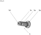
- FIG. 2 illustrates the hollow shaft 5. It can be seen that it comprises a cylindrical body 5a, provided at one end with a flat 5b and at the other end with a base 5c also cylindrical, this base being provided with perforations designed to cooperate with a fixing system of the rod and bolt type so as to secure the hollow shaft 5 to the stator of the motor 3.
- the hollow shaft 5 is pierced through and through so as to obtain a slot 5d, through which control cables and power supply cables or hoses of the motor 3 can pass.
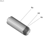
- FIG 3 illustrates a hollow cylinder 4a comprising, near each of its ends, a set of peripheral cutouts 4d associated with axial cutouts 4e each extending from one end of the hollow cylinder 4a to a peripheral cutout 4d.
- the set formed by an axial cutout 4e and a peripheral cutout 4d is designed so that a shoulder 4f provided in a flange 4b,4c can be inserted in translation into the axial cutout 4e and then locked in the peripheral cutout 4d by relative rotation of the flange 4b,4c relative to the hollow cylinder 4a.
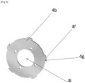
- each flange 4b,4c comprises at least two 4f shoulders, arranged in particular diametrically opposite. In order to have better support, a higher number of 4f shoulders is considered, for example five shoulders, arranged with a substantially constant angular distance between them.
- each shoulder 4f is provided with a groove 4g on the ends coming into abutment with the hollow cylinder 4a during rotation of the flange 4b, 4c, so that the hollow cylinder 4a engages in the groove 4g during rotation.
- a groove 4g makes it possible to limit the radial translation of the flange 4b, 4c.
- a rear flange 4c includes an axial opening 4h and is secured to the hollow shaft 5 and the stator of the motor 3 by means of removable securing means, for example screw/bolt assemblies or blind rivets. Once secured, the axial opening 4h of the rear flange 4c corresponds with the outside diameter of the body of the hollow shaft 5 so that the control cables and power cables or hoses of the motor can be connected to the outside of the cylindrical casing 4a,4b,4c.
- two rear flanges 4c are used to prevent possible loosening of the hollow cylinder 4a due to vibrations of the system. They are then locked in opposite directions of rotation.
- the use of two flanges 4c thus fixed to the hollow cylinder 4a and secured together by means of the removable securing means with the hollow shaft 5 makes it possible to eliminate the risk of disengagement of a flange 4c due to a rotation opposite to the direction of engagement of the shoulders 4f.
- a front flange 4b also comprises an axial opening 4i, allowing, unlike the rear flanges 4c, the output shaft of the epicyclic gear train 2 to pass through.
- a front flange 4b also comprises at least two shoulders 4f each capable of cooperating with an assembly formed by an axial cutout 4e and a cutout peripheral 4d near one end of the hollow cylinder 4a.
- a groove 4g is also present at the end of each shoulder 4f intended to come into contact with the cylinder 4a.
- a front flange 4b is secured to the housing of the epicyclic gear train 2 by means of removable securing means, for example screw/bolt assemblies or blind rivets. Once secured, the axial opening of the rear flange 4c corresponds with the output shaft of the epicyclic gear train 2 so that the cylindrical casing 4a,4b,4c is not subjected to the rotation of the output shaft.
- two front flanges 4b are used. They are then locked in rotation in opposite directions.
- the use of two flanges 4b thus fixed to the first outer casing and secured together by means of the removable securing means with the hollow shaft 5 makes it possible to eliminate the disengagement of a flange due to a rotation opposite to the direction of engagement of the shoulders in the hollow cylinder 4a.
- the cylindrical casing 4a, 4b, 4c thus formed insulates the geared motor 1 from the outside while providing an outlet on the one hand for control cables and power supply cables or hoses of the motor 3 and on the other hand for the output shaft of the epicyclic gear train 2.
- the cylindrical casing 4a, 4b, 4c makes it possible to perfectly isolate the motor from the outside, thus protecting it from possible damage.
- the hollow shaft 5 and the epicyclic output shaft 2 define the axis of rotation of the geared motor 1, so that it can be easily integrated into a mechanical system without inducing eccentricity of movement. Indeed, it is easier to center an axis relative to the mechanism than to center an axis linked to the rotor of a motor and a stator having a spatial extension.
- the cylindrical casing 4a, 4b, 4c has the additional advantage of being able to be easily dismantled for the maintenance of the motor or epicyclic gear train. The state of the art shows sealed geared motors on this point, the maintenance of which involves destructive dismantling of the casing, thus implying that a new casing must be recreated afterwards.
- the cylindrical casing 4a, 4b, 4c also has insulation from dust and/or water by adding sealing means at the junction between the flanges 4b, 4c and the cylinder 4a, between the rear flanges 4c and the hollow shaft 5 and/or between the front flanges 4b and the output shaft of the epicyclic gear train 2.
- the geared motor 1 thus formed is arranged in a drum held at its two ends by flanges 6b, 6c, making it possible to transfer the rotational movement of the output shaft of the epicyclic gear train 2 to the drum.
- the front flange 6b illustrated by the figure 6 , is fixed on the output shaft of the epicyclic gear train 2 and on the drum. It comprises an axis of rotation 6e as well as external fixing means 6f.
- the 6c rear flange illustrated by the figure 7 , comprises a light 6g provided with a bearing 6h through which the hollow shaft 5 is inserted.
- the bearing 6h can be a ball bearing or a mechanical seal. It allows the decoupling of the rotation of the drum relative to the hollow shaft 5.
- the rear flange 6c comprises external fixing means 6i.
- flanges 6b,6c ensure that the cylindrical casing 4a,4b,4b and the drum are coaxial, so as to avoid the formation of a reactive moment resulting from an eccentricity of the drum which could lead to variations in the speed of unwinding or winding of the rope.
- the drum provides a contact or fixing surface for a larger rotating element. This is particularly the case when the tubular motor is used in a winding/unwinding system, such as that of a removable cover.
- the drum may be cylindrical or prismatic. Examples include square or hexagonal prisms providing bearing surfaces for the drum to improve torque communication to a rotating surface.
- the tubular motor thus defined can accept indifferently any motor with dimensions compatible with the cylindrical casing, arranged axially with respect to the epicyclic gear train. Thus, even if it is common to have electric geared motors with such a configuration, the latter have a low rotation speed and/or a low torque.
- Axial hydraulic or pneumatic geared motors are not currently available. Such axial hydraulic or pneumatic geared motors provide high torque from hydraulic or pneumatic circuits on board a vehicle, particularly heavy goods vehicles or railway vehicles, while maintaining a small footprint.
- an actuation system 10 comprises a tubular motor as described above arranged in a casing 11, provided with a fixing 11a, 11b of the hollow axis 5 of the rear flange 6c, and a drive assembly 12b, 12c coupled to the front flange 6b.
- the casing 11 is in particular fixed to the chassis of a vehicle or a building so as to limit the return reaction of the actuation.
- the fastener 11a, 11b forms a clamp cooperating with the flats 5b formed on the hollow shaft 5 so as to prevent rotation thereof.
- the rotation of the motor is then transmitted to the drum 7.
- the drum 7 allows you to roll up or unroll any canvas, fabric, blanket, conveyor belt, cable or rope.
- the actuation system 10 is rendered inoperable.
- the attachment 11a, 11b can be opened so that the hollow shaft 5 is free to rotate, while being held in position by the rear flange 6c.
- the motor connections, in particular hydraulic or pneumatic, are disconnected using quick connectors, so as to reduce their inertia.
- a crank 12a can then be connected to the drive assembly 12b, 12c so as to be able to impart rotation to the drum via the axis of the front flange 6b.
- the functions of the actuation system are restored in a manual operating mode.
- the drive assembly 12b, 12c may include gear wheels, pinions and/or crown gears.
- the judicious choice of the gear ratios of the selected elements allows the manual operation of the actuation system with a restricted force.
- the drive assembly includes an element, not illustrated, arranged integrally with the axis 6e and meshed with the other elements.
- fixing 11a, 11b and the drive assembly 12b, 12c are integral with the casing and the tubular motor by means of the flanges. They then contribute to maintaining the tubular motor in axial position.
- a gasket illustrated on the figure 8 secured to the covering 11, keeps the hollow axis aligned when the fixing 11a, 11b is open.
- Such an actuation system avoids the need for an expensive, bulky and high-maintenance clutch to switch from engine actuation to manual actuation.
- maintenance of an actuation system according to the invention allows removal of the tubular motor for exchange or repair while the drum remains in place in the system. This is particularly advantageous in that it is not necessary to remove the canvas, fabric, cover, conveyor belt, cable or rope wound on the drum. The duration and cost of maintenance are thus greatly reduced.
Landscapes
- Engineering & Computer Science (AREA)
- General Engineering & Computer Science (AREA)
- Mechanical Engineering (AREA)
- Power Engineering (AREA)
- Connection Of Motors, Electrical Generators, Mechanical Devices, And The Like (AREA)
- Retarders (AREA)
Description
- L'invention a pour domaine technique les motoréducteurs, et plus particulièrement les moteurs tubulaires munis de tels motoréducteurs.
- De l'état de la technique antérieure, les documents suivants sont connus.
- Le document
US2019305629 divulgue un moteur à tambour. Le documentFR3016013 US2008/197733 divulgue un moteur électrique et une unité de transmission pour des actionneurs dans un véhicule à moteur. On connaît également le documentJP 2002276742 - L'invention a pour objet un motoréducteur comprenant un train épicycloïdal couplé à l'arbre de sortie d'un moteur. Le motoréducteur comprend une enveloppe cylindrique isolant le motoréducteur de l'extérieur et un arbre creux lié au stator du moteur et aligné avec l'arbre de sortie du train épicycloïdal, l'enveloppe cylindrique comprend un cylindre creux, deux brides avant et deux brides arrières,
- les deux brides avant étant solidarisées avec le carter du train épicycloïdal, les deux brides arrières étant solidarisées avec l'arbre creux,
- le cylindre creux étant muni à proximité de chacune de ses extrémités d'un ensemble de découpes périphériques associées à des découpes axiales s'étendant chacune depuis une extrémité du cylindre creux jusqu'à une découpe périphérique,
- les brides avant et les brides arrières étant munies chacune de lumières axiales et d'au moins deux épaulements, chaque épaulement étant apte à coopérer avec un ensemble formé par une découpe axiale et une découpe périphérique à proximité d'une extrémité du cylindre creux, de sorte à former l'enveloppe cylindrique et à la verrouiller par rotation des brides par rapport au cylindre creux chacune des deux brides avant et chacune des deux brides arrières étant verrouillées selon des sens de rotation opposés.
- Les brides arrières sont munies de lumières, qui peuvent permettre d'accommoder l'arbre creux.
- Les brides avant sont munies de lumières, qui peuvent permettre d'accommoder l'arbre de sortie du train épicycloïdal.
- Chaque bride peut comprendre cinq épaulements, le cylindre creux comprenant un nombre correspondant d'ensembles de découpes radiales et axiales.
- Chaque épaulement peut être muni d'une gorge de sorte que le cylindre creux vienne s'engager dans la gorge lors de la rotation relative de l'épaulement et du cylindre creux.
- Le moteur peut être un moteur électrique, hydraulique, pneumatique ou oléopneumatique.
- L'arbre creux peut comprendre une lumière à travers laquelle l'alimentation et la commande du moteur traversent l'enveloppe cylindrique.
- L'invention a également pour objet un moteur tubulaire comprenant un motoréducteur tel que défini ci-dessus, connecté à un tambour rotatif s'étendant autour de l'enveloppe cylindrique, un flasque avant solidaire de l'axe de sortie du train épicycloïdal du motoréducteur et d'un flasque arrière reposant de façon libre en rotation sur l'arbre creux (5) du motoréducteur les flasques étant solidaires du tambour de sorte que la rotation de l'axe de sortie du train épicycloïdal soit transmise au tambour et que l'axe de rotation du tambour rotatif soit coaxial avec l'axe de rotation du motoréducteur s'étendant à travers l'arbre creux et l'arbre de sortie du train épicycloïdal.
- Le flasque arrière peut être muni d'un palier coopérant avec l'arbre creux de sorte à décorréler le motoréducteur de la rotation du tambour rotatif.
- Un autre objet de l'invention est un système d'actionnement comprenant un moteur tubulaire tel que décrit ci-dessus, disposé dans un habillage, le système d'actionnement comprenant en outre une fixation de l'axe creux du flasque arrière sur l'habillage, et un ensemble d'entrainement couplé au flasque avant et apte à recevoir une manivelle, la fixation étant adaptée pour être ouverte lorsque le système d'actionnement est actionné avec la manivelle.
- Le moteur tubulaire peut être muni de connecteurs à déconnexion rapide de sorte à isoler le moteur tubulaire de sa source d'énergie lorsque le système d'actionnement est actionné avec la manivelle.
- D'autres buts, caractéristiques et avantages de l'invention apparaîtront à la lecture de la description suivante, donnée uniquement à titre d'exemple non limitatif et faite en référence aux dessins annexés sur lesquels :
- [
Fig 1 ] illustre un moteur tubulaire selon l'invention, - [
Fig 2 ] illustre un axe creux de l'invention, - [
Fig 3 ] illustre une enveloppe cylindrique de l'invention, - [
Fig 4 ] illustre une bride arrière de l'invention, - [
Fig 5 ] illustre une bride avant de l'invention, - [
Fig 6 ] illustre un flasque arrière de l'invention, - [
Fig 7 ] illustre un flasque avant de l'invention, et - [
Fig 8 ] illustre un système d'actionnement selon l'invention. - La
figure 1 illustre un motoréducteur 1 comprenant un train épicycloïdal 2 monté par l'intermédiaire d'une bride en périphérie de l'arbre de sortie d'un moteur 3, l'ensemble étant contenu dans une enveloppe cylindrique 4a,4b,4c. L'enveloppe cylindrique 4a,4b,4c est fixe et comprend un cylindre creux 4a fermé à ses deux extrémités par des brides avant 4b et des brides arrière 4c. - Le motoréducteur 1 est également muni d'un arbre creux 5 fixé au stator soutenu par un flasque arrière 6c, le motoréducteur 1 étant par ailleurs muni d'un flasque avant 6b lié à l'arbre de sortie du train épicycloïdal 2.
- La
figure 2 illustre l'arbre creux 5. On peut voir qu'il comprend un corps cylindrique 5a, muni à une extrémité d'un méplat 5b et à l'autre extrémité d'une base 5c également cylindrique, cette base étant munie de perforations conçues pour coopérer avec un système de fixation de type tiges et boulons de sorte à solidariser l'arbre creux 5 sur le stator du moteur 3. L'arbre creux 5 est percé de part en part de sorte à obtenir une lumière 5d, par l'intermédiaire de laquelle des câbles de commande et des câbles ou flexibles d'alimentation du moteur 3 peuvent transiter. - La
figure 3 illustre un cylindre creux 4a comprenant à proximité de chacune de ses extrémités, un ensemble de découpes périphériques 4d associées à des découpes axiales 4e s'étendant chacune depuis une extrémité du cylindre creux 4a jusqu'à une découpe périphérique 4d. L'ensemble formé par une découpe axiale 4e et une découpe périphérique 4d est conçu de sorte qu'un épaulement 4f prévu dans une bride 4b,4c puisse être inséré en translation dans la découpe axiale 4e puis verrouillé dans la découpe périphérique 4d par rotation relative de la bride 4b,4c par rapport au cylindre creux 4a. - Les
figures 4 et5 illustrent des brides 4b,4c munies de tels épaulements 4f. Afin de permettre le maintien en position par rapport au cylindre creux 4a, chaque bride 4b,4c comporte au moins deux épaulements 4f, disposés notamment de façon diamétralement opposée. Afin de disposer d'un meilleur maintien, un nombre plus élevé d'épaulements 4f est considéré, par exemple cinq épaulements, disposés avec un écart angulaire sensiblement constant entre eux. - Afin d'améliorer encore le maintien de la position des brides 4b,4c par rapport au cylindre creux 4a, chaque épaulement 4f est muni d'une gorge 4g sur l'extrémités arrivant en buté avec le cylindre creux 4a lors de la rotation de la bride 4b,4c, de sorte que le cylindre creux 4a vienne s'engager dans la gorge 4g lors de la rotation. Une telle gorge 4g permet de limiter la translation radiale de la bride 4b,4c.
- Une bride arrière 4c comprend une ouverture axiale 4h et est solidarisée avec l'arbre creux 5 et le stator du moteur 3 par l'intermédiaire de moyens de solidarisation amovibles, par exemple des ensembles vis/boulon ou des rivets borgnes. Une fois solidarisés, l'ouverture axiale 4h de la bride arrière 4c correspond avec le diamètre extérieur du corps de l'arbre creux 5 de sorte que les câbles de commande et des câbles ou flexibles d'alimentation du moteur puisse être connectés à l'extérieur de l'enveloppe cylindrique 4a,4b,4c.
- Dans un mode de réalisation particulier, deux brides arrière 4c sont employées pour éviter un éventuel desserrage du cylindre creux 4a du fait des vibrations du système. Elles sont alors verrouillées selon des sens de rotation opposés. L'utilisation de deux brides 4c ainsi fixées au cylindre creux 4a et solidarisées ensemble par l'intermédiaire des moyens de solidarisation amovibles avec l'arbre creux 5 permet d'éliminer le risque de désengagement d'une bride 4c du fait d'une rotation opposée au sens d'engagement des épaulements 4f.
- Une bride avant 4b comprend également une ouverture axiale 4i, permettant, à la différence des brides arrière 4c, de faire passer l'arbre de sortie du train épicycloïdal 2. Une bride avant 4b comprend également au moins deux épaulements 4f aptes chacun à coopérer avec un ensemble formé par une découpe axiale 4e et une découpe périphérique 4d à proximité d'une extrémité du cylindre creux 4a. Une gorge 4g est également présente à l'extrémité de chaque épaulement 4f destinée à entrer en contact avec le cylindre 4a.
- Une bride avant 4b est solidarisée avec le carter du train épicycloïdal 2 par l'intermédiaire de moyens de solidarisation amovibles, par exemple des ensembles vis/boulon ou des rivets borgnes. Une fois solidarisés, l'ouverture axiale de la bride arrière 4c correspond avec l'arbre de sortie du train épicycloïdal 2 de sorte que l'enveloppe cylindrique 4a,4b,4c n'est pas soumise à la rotation de l'arbre de sortie.
- Comme pour les brides arrière 4c, dans un mode de réalisation particulier, deux brides avant 4b sont employées. Elles sont alors verrouillées en rotation selon des sens opposés. L'utilisation de deux brides 4b ainsi fixées à la première enveloppe extérieure et solidarisées ensemble par l'intermédiaire des moyens de solidarisation amovibles avec l'arbre creux 5 permet d'éliminer le désengagement d'une bride du fait d'une rotation opposée au sens d'engagement des épaulements dans le cylindre creux 4a.
- L'enveloppe cylindrique 4a,4b,4c ainsi constituée isole le motoréducteur 1 de l'extérieur tout en ménageant une sortie d'une part pour des câbles de commande et des câbles ou flexibles d'alimentation du moteur 3 et d'autre part pour l'axe de sortie du train épicycloïdal 2.
- En ne s'appuyant pas sur un carter moteur, l'enveloppe cylindrique 4a,4b,4c permet de parfaitement isoler le moteur de l'extérieur, le protégeant ainsi d'éventuels dommages. De plus, l'axe creux 5 et l'axe de sortie épicycloïdal 2 définissent l'axe de rotation du motoréducteur 1, de sorte à pouvoir être aisément intégré dans un système mécanique sans induire d'excentricité de mouvement. En effet, il plus aisé de centrer un axe par rapport à mécanisme que de centrer un axe lié au rotor d'un moteur et un stator présentant une extension spatiale. Par ailleurs, l'enveloppe cylindrique 4a,4b,4c présente l'avantage additionnel de pouvoir être aisément démontable pour la maintenance du moteur ou du train épicycloïdal. L'état de la technique montre sur ce point des motoréducteurs scellés, dont la maintenance implique un démontage destructif de l'enveloppe impliquant ainsi qu'une nouvelle enveloppe doit être recrée à postériori.
- Dans un mode de réalisation particulier, l'enveloppe cylindrique 4a,4b,4c présente en plus une isolation aux poussières et/ou à l'eau par ajout de moyens d'étanchéité à la jonction entre les brides 4b,4c et le cylindre ceux 4a, entre les brides arrière 4c et l'axe creux 5 et/ou entre les brides avant 4b et l'arbre de sortie du train épicycloïdal 2.
- Afin de former un moteur tubulaire, le motoréducteur 1 ainsi constitué est disposé dans un tambour maintenu à ses deux extrémités par des flasques 6b,6c, permettant de transférer le mouvement de rotation de l'axe de sortie du train épicycloïdal 2 au tambour.
- Le flasque avant 6b, illustré par la
figure 6 , est fixé sur l'arbre de sortie du train épicycloïdal 2 et sur le tambour. Il comprend un axe de rotation 6e ainsi que des moyens de fixation externe 6f. - Le flasque arrière 6c, illustré par la
figure 7 , comprend une lumière 6g munie d'un palier 6h à travers lesquels est inséré l'arbre creux 5. Le palier 6h peut être un roulement à bille ou une garniture mécanique. Il permet le découplage de la rotation du tambour par rapport à l'arbre creux 5. Comme le flasque avant 6b, le flasque arrière 6c comprend des moyens de fixation externe 6i. - Des moyens de fixation externe 6f,6i permettant de fixer le tambour sur les flasques, et éventuellement, en plus, un élément tournant plus important.
- Ces flasques 6b,6c permettent d'assurer que l'enveloppe cylindrique 4a,4b,4b et le tambour sont coaxiaux, de sorte à éviter la formation d'un moment réactif résultant d'une excentricité du tambour pouvant mener à des variations de vitesse de dévidement ou d'enroulement de la corde.
- Le tambour permet d'offrir une surface de contact ou de fixation à un élément tournant plus important. C'est notamment le cas lorsque le moteur tubulaire est employé dans un système enrouleur/dérouleur, comme celui d'une couverture amovible.
- Le tambour peut être cylindrique ou en forme de prisme. On citera notamment des prismes à base carrée ou hexagonale conférant des surfaces d'appui au tambour, afin d'améliorer la communication de couple à une surface tournante.
- Le moteur tubulaire ainsi défini peut accepter indifféremment tout moteur aux dimensions compatibles avec l'enveloppe cylindrique, disposé de façon axiale par rapport au train épicycloïdal. Ainsi, même s'il est courant de disposer de motoréducteurs électriques présentant une telle configuration, ces derniers présentent une faible vitesse de rotation et/ou un faible couple.
- Des motoréducteurs hydrauliques ou pneumatiques axiaux ne sont pas disponibles à l'heure actuelle. De tels motoréducteurs hydrauliques ou pneumatiques axiaux permettent de disposer d'un couple important à partir de circuits hydrauliques ou pneumatiques embarqués sur un véhicule, notamment des poids lourds ou des engins ferroviaires, tout en conservant un encombrement réduit.
- Dans un mode de réalisation particulier, illustré par la
figure 8 , un système d'actionnement 10 comprend un moteur tubulaire tel que décrit ci-dessus disposé dans un habillage 11, muni d'une fixation 11a,11b de l'axe creux 5 du flasque arrière 6c, et un ensemble d'entrainement 12b,12c couplé au flasque avant 6b. L'habillage 11 est notamment fixé au châssis d'un véhicule ou d'un bâtiment de sorte à limiter la réaction en retour de l'actionnement. - La fixation 11a,11b forme une pince coopérant avec les méplats 5b formés sur l'axe creux 5 de sorte à en empêcher la rotation. La rotation du moteur est alors transmise au tambour 7. Le tambour 7 permet d'enrouler ou de dérouler toute toile, tissu, couverture, bande de convoyeur, câble ou cordage.
- Néanmoins, lorsqu'un défaut ou un problème d'alimentation a lieu au niveau du moteur, le système d'actionnement 10 est rendu inopérable.
- Afin de restaurer une opération manuelle du système d'actionnement 10, la fixation 11a,11b peut être ouverte de sorte que l'axe creux 5 est rendu libre en rotation, tout en étant maintenu en position par le flasque arrière 6c. Les connexions du moteur, notamment hydrauliques ou pneumatiques, sont déconnectées grâce à des raccords rapides, de sorte à en réduire l'inertie. Une manivelle 12a peut alors être connectée à l'ensemble d'entrainement 12b,12c de sorte à pouvoir imprimer une rotation au tambour par l'intermédiaire de l'axe du flasque avant 6b. Les fonctions du système d'actionnement sont restaurées dans un mode d'opération manuel.
- L'ensemble d'entrainement 12b,12c peut comprend des roues dentées, des pignons et/ou des couronnes dentées. Le choix judicieux des rapports d'engrenage des éléments choisis permet l'opération manuelle du système d'actionnement avec une force restreinte. Il est à noter que l'ensemble d'entrainement comprend un élément, non illustré, disposé solidairement avec l'axe 6e et engrainé avec les autres éléments.
- Il est à noter que la fixation 11a,11b et l'ensemble d'entraînement 12b,12c sont solidaires de l'habillage et du moteur tubulaire par l'intermédiaire des flasques. Ils contribuent alors au maintien en position axiale du moteur tubulaire. Une garniture illustrée sur la
figure 8 , solidaire de l'habillage 11, permet de maintenir l'axe creux aligné lorsque la fixation 11a,11b est ouverte. - Un tel système d'actionnement permet d'éviter d'utiliser un embrayage couteux, encombrant et nécessitant une maintenance élevée pour passer d'un actionnement par le moteur à un actionnement manuel.
- De plus, la maintenance d'un système d'actionnement selon l'invention permet un retrait du moteur tubulaire pour échange ou réparation alors que le tambour demeure en place dans le système. Cela est particulièrement avantageux dans la mesure où l'on est dispensé du retrait de la toile, tissu, couverture, bande de convoyeur, câble ou cordage enroulé sur le tambour. La durée et le cout de la maintenance s'en trouvent ainsi grandement réduits.
Claims (11)
- Motoréducteur comprenant un train épicycloïdal (2) couplé à un arbre de sortie d'un moteur (3), comprenant une enveloppe cylindrique (4a,4b,4c) isolant le motoréducteur (1) de l'extérieur et, un arbre creux (5) lié au stator du moteur (3) et aligné avec l'arbre de sortie du train épicycloïdal (2), l'enveloppe cylindrique (4a,4b,4c) comprenant un cylindre creux (4a), caractérisé par le fait que l'enveloppe cylindrique (4a,4b,4c) comprend en outre deux brides avant (4b) et deux brides arrières (4c),les deux brides avant (4b) étant solidarisées avec le carter du train épicycloïdal (2), les deux brides arrières (4c) étant solidarisées avec l'arbre creux (5),le cylindre creux (4a) étant muni à proximité de chacune de ses extrémités d'un ensemble de découpes périphériques (4d) associées à des découpes axiales (4e) s'étendant chacune depuis une extrémité du cylindre creux (4a) jusqu'à une découpe périphérique (4d),les brides avant (4b) et les brides arrières (4c) étant munies chacune de lumières axiales et d'au moins deux épaulements (4f), chaque épaulement (4f) étant apte à coopérer avec un ensemble formé par une découpe axiale (4e) et une découpe périphérique (4d) à proximité d'une extrémité du cylindre creux (4a), de sorte à former l'enveloppe cylindrique (4a,4b,4c) et à la verrouiller par rotation des brides (4b,4c) par rapport au cylindre creux (4a), chacune des deux brides avant (4b) et chacune des deux brides arrières (4c) étant verrouillées selon des sens de rotation opposés.
- Motoréducteur selon la revendication 1, dans lequel les lumières des brides arrières (4c) permettent d'accommoder l'arbre creux (5).
- Motoréducteur selon l'une quelconque des revendications1 ou 2, dans lequel les lumières des brides avant (4b) permettent d'accommoder l'arbre de sortie du train épicycloïdal.
- Motoréducteur selon l'une quelconque des revendications précédentes, dans lequel chaque bride comprend cinq épaulements, le cylindre creux (4a) comprenant un nombre correspondant d'ensembles de découpes radiales et axiales.
- Motoréducteur selon l'une quelconque des revendications précédentes, dans lequel chaque épaulement (4f) est muni d'une gorge (4g) de sorte que le cylindre creux (4a) vienne s'engager dans la gorge (4g) lors de la rotation relative de l'épaulement (4f) et du cylindre creux (4a).
- Motoréducteur selon l'une quelconque des revendications précédentes, dans lequel le moteur (3) est un moteur électrique, hydraulique, pneumatique ou oléopneumatique.
- Motoréducteur selon l'une quelconque des revendications précédentes, dans lequel l'arbre creux (5) comprend une lumière (5d) à travers laquelle l'alimentation et la commande du moteur (3) traversent l'enveloppe cylindrique (4a,4b,4c).
- Moteur tubulaire comprenant un motoréducteur 1 selon l'une quelconque des revendications 1 à 7 caractérisé par le fait qu'il comprend un tambour rotatif s'étendant autour de l'enveloppe cylindrique (4a,4b,4c), un flasque avant (6b) solidaire de l'axe de sortie du train épicycloïdal du motoréducteur et un flasque arrière (6c) reposant de façon libre en rotation sur l'arbre creux (5) du motoréducteur, les flasques étant solidaires du tambour de sorte que la rotation de l'axe de sortie du train épicycloïdal soit transmise au tambour et que l'axe de rotation du tambour rotatif soit coaxial avec l'axe de rotation du motoréducteur (1) s'étendant à travers l'arbre creux (5) et l'arbre de sortie du train épicycloïdal (2).
- Moteur tubulaire selon la revendication 8, dans lequel le flasque arrière (6c) est muni d'un palier (6h) coopérant avec l'arbre creux (5) de sorte à décorréler le motoréducteur (1) de la rotation du tambour rotatif.
- Système d'actionnement comprenant un moteur tubulaire selon l'une quelconque des revendications 8 ou 9 disposé dans un habillage (11), le système d'actionnement comprenant en outre une fixation (11a,11b) de l'axe creux du flasque arrière (6c) sur l'habillage (11), et un ensemble d'entrainement (12b,12c) couplé au flasque avant (6b) et apte à recevoir une manivelle (12a), la fixation (11a,11b) étant adaptée pour être ouverte lorsque le système d'actionnement est actionné avec la manivelle (12a).
- Système d'actionnement selon la revendication 10, dans lequel le moteur tubulaire est muni de connecteurs à déconnexion rapide de sorte à isoler le moteur tubulaire de sa source d'énergie lorsque le système d'actionnement est actionné avec la manivelle (12a).
Applications Claiming Priority (3)
| Application Number | Priority Date | Filing Date | Title |
|---|---|---|---|
| FR2007238A FR3112373B1 (fr) | 2020-07-08 | 2020-07-08 | Motoréducteur à enveloppe cylindrique et moteur tubulaire correspondant. |
| FR2009887A FR3112374B1 (fr) | 2020-07-08 | 2020-09-29 | Motoréducteur à enveloppe cylindrique et moteur tubulaire correspondant. |
| PCT/FR2021/051248 WO2022008840A1 (fr) | 2020-07-08 | 2021-07-06 | Motoréducteur à enveloppe cylindrique et moteur tubulaire correspondant |
Publications (3)
| Publication Number | Publication Date |
|---|---|
| EP4179610A1 EP4179610A1 (fr) | 2023-05-17 |
| EP4179610C0 EP4179610C0 (fr) | 2024-10-16 |
| EP4179610B1 true EP4179610B1 (fr) | 2024-10-16 |
Family
ID=72801690
Family Applications (1)
| Application Number | Title | Priority Date | Filing Date |
|---|---|---|---|
| EP21746524.4A Active EP4179610B1 (fr) | 2020-07-08 | 2021-07-06 | Motoréducteur à enveloppe cylindrique et moteur tubulaire correspondant |
Country Status (8)
| Country | Link |
|---|---|
| US (1) | US12352351B2 (fr) |
| EP (1) | EP4179610B1 (fr) |
| CN (1) | CN116250168A (fr) |
| CA (1) | CA3183964A1 (fr) |
| ES (1) | ES3001907T3 (fr) |
| FR (2) | FR3112373B1 (fr) |
| PL (1) | PL4179610T3 (fr) |
| WO (1) | WO2022008840A1 (fr) |
Families Citing this family (1)
| Publication number | Priority date | Publication date | Assignee | Title |
|---|---|---|---|---|
| USD1124071S1 (en) * | 2024-10-16 | 2026-04-28 | Guangdong Maijie Industrial Co., Ltd. | Gear motor |
Family Cites Families (8)
| Publication number | Priority date | Publication date | Assignee | Title |
|---|---|---|---|---|
| JP2002276742A (ja) * | 2001-03-09 | 2002-09-25 | Shunho Kyo | 内歯車が外方旋回するドラム式モータ |
| US6672402B2 (en) * | 2001-12-27 | 2004-01-06 | Black & Decker Inc. | Combined fastenerless motor end cap and output device mounting |
| DE102005030217A1 (de) * | 2005-06-29 | 2007-01-04 | Robert Bosch Gmbh | Elektromotor und Getriebe-Antriebseinheit für Stellantriebe im Kraftfahrzeug |
| JP5604338B2 (ja) * | 2011-03-07 | 2014-10-08 | Ntn株式会社 | 電気自動車用駆動装置 |
| FR3016013B1 (fr) * | 2013-12-30 | 2016-02-12 | Chassis Brakes Int Bv | Actionneur de frein a tambour avec motorisation par emboitement a jeu angulaire |
| JP6478863B2 (ja) * | 2015-07-31 | 2019-03-06 | 株式会社ミツバ | アクチュエータおよび車両ドア開閉用アクチュエータ |
| DE102016112036A1 (de) * | 2016-06-30 | 2018-01-04 | Interroll Holding Ag | Antriebseinheit für einen Trommelmotor, Trommelmotor, Hinterflansch und Herstellungsverfahren |
| JP7009723B2 (ja) * | 2018-05-29 | 2022-01-26 | ▲無▼▲錫▼小天鵝電器有限公司 | ドラム式洗濯機用の制動器及びドラム式洗濯機 |
-
2020
- 2020-07-08 FR FR2007238A patent/FR3112373B1/fr active Active
- 2020-09-29 FR FR2009887A patent/FR3112374B1/fr active Active
-
2021
- 2021-07-06 CA CA3183964A patent/CA3183964A1/fr active Pending
- 2021-07-06 WO PCT/FR2021/051248 patent/WO2022008840A1/fr not_active Ceased
- 2021-07-06 PL PL21746524.4T patent/PL4179610T3/pl unknown
- 2021-07-06 EP EP21746524.4A patent/EP4179610B1/fr active Active
- 2021-07-06 ES ES21746524T patent/ES3001907T3/es active Active
- 2021-07-06 CN CN202180048940.6A patent/CN116250168A/zh active Pending
- 2021-07-06 US US18/005,322 patent/US12352351B2/en active Active
Also Published As
| Publication number | Publication date |
|---|---|
| FR3112374B1 (fr) | 2023-04-21 |
| WO2022008840A1 (fr) | 2022-01-13 |
| EP4179610A1 (fr) | 2023-05-17 |
| ES3001907T3 (en) | 2025-03-06 |
| US20230272849A1 (en) | 2023-08-31 |
| EP4179610C0 (fr) | 2024-10-16 |
| FR3112373B1 (fr) | 2023-04-21 |
| US12352351B2 (en) | 2025-07-08 |
| CN116250168A (zh) | 2023-06-09 |
| CA3183964A1 (fr) | 2022-01-13 |
| FR3112374A1 (fr) | 2022-01-14 |
| FR3112373A1 (fr) | 2022-01-14 |
| PL4179610T3 (pl) | 2025-03-31 |
Similar Documents
| Publication | Publication Date | Title |
|---|---|---|
| EP3854680B1 (fr) | Aéronef à voilure tournante muni d'un système de transmission équipé d'un moteur électrique de secours | |
| EP2372187B1 (fr) | Réducteur et actionneur électrique comprenant un tel réducteur | |
| EP0790385A1 (fr) | Dispositif de manoeuvre pour volet roulant | |
| EP3581416A1 (fr) | Dispositif de transmission, notamment pour véhicule électrique | |
| EP2783062A2 (fr) | Actionneur électrique tubulaire d'entraînement pour un écran domotique, procédé d'assemblage d'un tel actionneur et installation comprenant un tel actionneur | |
| FR3064620A1 (fr) | Systeme de transfert de fluide a actionneurs munis de reducteurs de vitesse reversibles | |
| CA3183964A1 (fr) | Motoreducteur a enveloppe cylindrique et moteur tubulaire correspondant | |
| FR3139554A1 (fr) | Ensemble de propulsion comprenant un système de transmission, plusieurs moteurs électriques et au moins un système d’accouplement déporté, aéronef comprenant au moins un tel ensemble de propulsion | |
| FR2975842A1 (fr) | Dispositif d'alimentation electrique d'au moins un equipement d'un rotor tournant d'un aeronef, et aeronef | |
| EP1653593B1 (fr) | Moteur électromécanique à double sortie | |
| EP0320416B1 (fr) | Collecteur rotatif pour l'alimentation du moteur électrique des dispositifs enrouleurs de toile ou autre organe de fermeture à manoeuvre de secours intégrée | |
| EP2816253B1 (fr) | Réducteur épicycloïdal pour actionneur d enroulement et de déroulement | |
| EP3140238B1 (fr) | Treuil modulaire embarque | |
| EP0775798A1 (fr) | Dispositif d'entraînement en rotation d'un élément d'enroulement de volet roulant | |
| EP0490755B1 (fr) | Mécanisme de transmission de puissance entre un arbre moteur et deux ensembles à entraîner, utilisable notamment sur les giravions | |
| FR3105812A1 (fr) | Train d’engrenages imbriqué à deux pignons solaires | |
| EP4279308B1 (fr) | Sous-ensemble hybride d'entraînement d'un véhicule | |
| EP0768981A1 (fr) | Treuil motorise, destine a l'amarrage de navires | |
| EP1691068A1 (fr) | Dispositif de démarrage d'un moteur thermique | |
| EP4406851A1 (fr) | Ensemble de propulsion électrique comportant plusieurs moteurs électriques accouplés à un même arbre d entrée d'un système de transmission, aéronef comportant au moins un tel ensemble de propulsion électrique | |
| EP4603723A1 (fr) | Motoréducteur électrique | |
| WO2025215330A1 (fr) | Système d'entraînement pour installation de transport par câble | |
| FR2996275A1 (fr) | Dispositif d'entrainement d'une poulie destinee a entrainer un cable de traction d'un telepherique, notament un telesiege ou telecabine | |
| FR2988456A1 (fr) | Dispositif reducteur de vitesse comprenant un train epicycloidal et une motorisation | |
| FR2747089A1 (fr) | Motoreducteur pour essuie-glace de vehicule automobile |
Legal Events
| Date | Code | Title | Description |
|---|---|---|---|
| STAA | Information on the status of an ep patent application or granted ep patent |
Free format text: STATUS: UNKNOWN |
|
| STAA | Information on the status of an ep patent application or granted ep patent |
Free format text: STATUS: THE INTERNATIONAL PUBLICATION HAS BEEN MADE |
|
| PUAI | Public reference made under article 153(3) epc to a published international application that has entered the european phase |
Free format text: ORIGINAL CODE: 0009012 |
|
| STAA | Information on the status of an ep patent application or granted ep patent |
Free format text: STATUS: REQUEST FOR EXAMINATION WAS MADE |
|
| 17P | Request for examination filed |
Effective date: 20230131 |
|
| AK | Designated contracting states |
Kind code of ref document: A1 Designated state(s): AL AT BE BG CH CY CZ DE DK EE ES FI FR GB GR HR HU IE IS IT LI LT LU LV MC MK MT NL NO PL PT RO RS SE SI SK SM TR |
|
| DAV | Request for validation of the european patent (deleted) | ||
| DAX | Request for extension of the european patent (deleted) | ||
| GRAP | Despatch of communication of intention to grant a patent |
Free format text: ORIGINAL CODE: EPIDOSNIGR1 |
|
| STAA | Information on the status of an ep patent application or granted ep patent |
Free format text: STATUS: GRANT OF PATENT IS INTENDED |
|
| INTG | Intention to grant announced |
Effective date: 20240524 |
|
| GRAS | Grant fee paid |
Free format text: ORIGINAL CODE: EPIDOSNIGR3 |
|
| GRAA | (expected) grant |
Free format text: ORIGINAL CODE: 0009210 |
|
| STAA | Information on the status of an ep patent application or granted ep patent |
Free format text: STATUS: THE PATENT HAS BEEN GRANTED |
|
| AK | Designated contracting states |
Kind code of ref document: B1 Designated state(s): AL AT BE BG CH CY CZ DE DK EE ES FI FR GB GR HR HU IE IS IT LI LT LU LV MC MK MT NL NO PL PT RO RS SE SI SK SM TR |
|
| REG | Reference to a national code |
Ref country code: GB Ref legal event code: FG4D Free format text: NOT ENGLISH |
|
| REG | Reference to a national code |
Ref country code: CH Ref legal event code: EP |
|
| REG | Reference to a national code |
Ref country code: IE Ref legal event code: FG4D Free format text: LANGUAGE OF EP DOCUMENT: FRENCH |
|
| REG | Reference to a national code |
Ref country code: DE Ref legal event code: R096 Ref document number: 602021020392 Country of ref document: DE |
|
| U01 | Request for unitary effect filed |
Effective date: 20241106 |
|
| U07 | Unitary effect registered |
Designated state(s): AT BE BG DE DK EE FI FR IT LT LU LV MT NL PT RO SE SI Effective date: 20241115 |
|
| REG | Reference to a national code |
Ref country code: ES Ref legal event code: FG2A Ref document number: 3001907 Country of ref document: ES Kind code of ref document: T3 Effective date: 20250306 |
|
| PG25 | Lapsed in a contracting state [announced via postgrant information from national office to epo] |
Ref country code: IS Free format text: LAPSE BECAUSE OF FAILURE TO SUBMIT A TRANSLATION OF THE DESCRIPTION OR TO PAY THE FEE WITHIN THE PRESCRIBED TIME-LIMIT Effective date: 20250216 Ref country code: HR Free format text: LAPSE BECAUSE OF FAILURE TO SUBMIT A TRANSLATION OF THE DESCRIPTION OR TO PAY THE FEE WITHIN THE PRESCRIBED TIME-LIMIT Effective date: 20241016 |
|
| PG25 | Lapsed in a contracting state [announced via postgrant information from national office to epo] |
Ref country code: NO Free format text: LAPSE BECAUSE OF FAILURE TO SUBMIT A TRANSLATION OF THE DESCRIPTION OR TO PAY THE FEE WITHIN THE PRESCRIBED TIME-LIMIT Effective date: 20250116 |
|
| PG25 | Lapsed in a contracting state [announced via postgrant information from national office to epo] |
Ref country code: GR Free format text: LAPSE BECAUSE OF FAILURE TO SUBMIT A TRANSLATION OF THE DESCRIPTION OR TO PAY THE FEE WITHIN THE PRESCRIBED TIME-LIMIT Effective date: 20250117 |
|
| PG25 | Lapsed in a contracting state [announced via postgrant information from national office to epo] |
Ref country code: RS Free format text: LAPSE BECAUSE OF FAILURE TO SUBMIT A TRANSLATION OF THE DESCRIPTION OR TO PAY THE FEE WITHIN THE PRESCRIBED TIME-LIMIT Effective date: 20250116 |
|
| PG25 | Lapsed in a contracting state [announced via postgrant information from national office to epo] |
Ref country code: SM Free format text: LAPSE BECAUSE OF FAILURE TO SUBMIT A TRANSLATION OF THE DESCRIPTION OR TO PAY THE FEE WITHIN THE PRESCRIBED TIME-LIMIT Effective date: 20241016 |
|
| PG25 | Lapsed in a contracting state [announced via postgrant information from national office to epo] |
Ref country code: SK Free format text: LAPSE BECAUSE OF FAILURE TO SUBMIT A TRANSLATION OF THE DESCRIPTION OR TO PAY THE FEE WITHIN THE PRESCRIBED TIME-LIMIT Effective date: 20241016 |
|
| PG25 | Lapsed in a contracting state [announced via postgrant information from national office to epo] |
Ref country code: CZ Free format text: LAPSE BECAUSE OF FAILURE TO SUBMIT A TRANSLATION OF THE DESCRIPTION OR TO PAY THE FEE WITHIN THE PRESCRIBED TIME-LIMIT Effective date: 20241016 |
|
| PLBE | No opposition filed within time limit |
Free format text: ORIGINAL CODE: 0009261 |
|
| STAA | Information on the status of an ep patent application or granted ep patent |
Free format text: STATUS: NO OPPOSITION FILED WITHIN TIME LIMIT |
|
| U20 | Renewal fee for the european patent with unitary effect paid |
Year of fee payment: 5 Effective date: 20250723 |
|
| 26N | No opposition filed |
Effective date: 20250717 |
|
| PGFP | Annual fee paid to national office [announced via postgrant information from national office to epo] |
Ref country code: ES Payment date: 20250812 Year of fee payment: 5 |
|
| REG | Reference to a national code |
Ref country code: CH Ref legal event code: H13 Free format text: ST27 STATUS EVENT CODE: U-0-0-H10-H13 (AS PROVIDED BY THE NATIONAL OFFICE) Effective date: 20260224 |
|
| GBPC | Gb: european patent ceased through non-payment of renewal fee |
Effective date: 20250706 |
|
| PG25 | Lapsed in a contracting state [announced via postgrant information from national office to epo] |
Ref country code: GB Free format text: LAPSE BECAUSE OF NON-PAYMENT OF DUE FEES Effective date: 20250706 |
|
| PG25 | Lapsed in a contracting state [announced via postgrant information from national office to epo] |
Ref country code: CH Free format text: LAPSE BECAUSE OF NON-PAYMENT OF DUE FEES Effective date: 20250731 |
|
| PGFP | Annual fee paid to national office [announced via postgrant information from national office to epo] |
Ref country code: PL Payment date: 20260622 Year of fee payment: 6 |
|
| PG25 | Lapsed in a contracting state [announced via postgrant information from national office to epo] |
Ref country code: IE Free format text: LAPSE BECAUSE OF NON-PAYMENT OF DUE FEES Effective date: 20250706 |
|
| PG25 | Lapsed in a contracting state [announced via postgrant information from national office to epo] |
Ref country code: MC Free format text: LAPSE BECAUSE OF FAILURE TO SUBMIT A TRANSLATION OF THE DESCRIPTION OR TO PAY THE FEE WITHIN THE PRESCRIBED TIME-LIMIT Effective date: 20241016 |
|
| U20 | Renewal fee for the european patent with unitary effect paid |
Year of fee payment: 6 Effective date: 20260626 |
|
| PG25 | Lapsed in a contracting state [announced via postgrant information from national office to epo] |
Ref country code: CY Free format text: LAPSE BECAUSE OF FAILURE TO SUBMIT A TRANSLATION OF THE DESCRIPTION OR TO PAY THE FEE WITHIN THE PRESCRIBED TIME-LIMIT Effective date: 20241016 |