EP4179274B1 - Absolute heading estimation with constrained motion - Google Patents
Absolute heading estimation with constrained motion Download PDFInfo
- Publication number
- EP4179274B1 EP4179274B1 EP21740005.0A EP21740005A EP4179274B1 EP 4179274 B1 EP4179274 B1 EP 4179274B1 EP 21740005 A EP21740005 A EP 21740005A EP 4179274 B1 EP4179274 B1 EP 4179274B1
- Authority
- EP
- European Patent Office
- Prior art keywords
- gyroscope
- vehicle
- pivoting
- rotation
- earth
- Prior art date
- Legal status (The legal status is an assumption and is not a legal conclusion. Google has not performed a legal analysis and makes no representation as to the accuracy of the status listed.)
- Active
Links
Images


Classifications
-
- G—PHYSICS
- G01—MEASURING; TESTING
- G01C—MEASURING DISTANCES, LEVELS OR BEARINGS; SURVEYING; NAVIGATION; GYROSCOPIC INSTRUMENTS; PHOTOGRAMMETRY OR VIDEOGRAMMETRY
- G01C21/00—Navigation; Navigational instruments not provided for in groups G01C1/00 - G01C19/00
- G01C21/10—Navigation; Navigational instruments not provided for in groups G01C1/00 - G01C19/00 by using measurements of speed or acceleration
- G01C21/12—Navigation; Navigational instruments not provided for in groups G01C1/00 - G01C19/00 by using measurements of speed or acceleration executed aboard the object being navigated; Dead reckoning
- G01C21/16—Navigation; Navigational instruments not provided for in groups G01C1/00 - G01C19/00 by using measurements of speed or acceleration executed aboard the object being navigated; Dead reckoning by integrating acceleration or speed, i.e. inertial navigation
-
- E—FIXED CONSTRUCTIONS
- E02—HYDRAULIC ENGINEERING; FOUNDATIONS; SOIL SHIFTING
- E02F—DREDGING; SOIL-SHIFTING
- E02F3/00—Dredgers; Soil-shifting machines
- E02F3/04—Dredgers; Soil-shifting machines mechanically-driven
- E02F3/28—Dredgers; Soil-shifting machines mechanically-driven with digging tools mounted on a dipper- or bucket-arm, i.e. there is either one arm or a pair of arms, e.g. dippers, buckets
- E02F3/36—Component parts
- E02F3/42—Drives for dippers, buckets, dipper-arms or bucket-arms
- E02F3/43—Control of dipper or bucket position; Control of sequence of drive operations
- E02F3/435—Control of dipper or bucket position; Control of sequence of drive operations for dipper-arms, backhoes or the like
-
- E—FIXED CONSTRUCTIONS
- E02—HYDRAULIC ENGINEERING; FOUNDATIONS; SOIL SHIFTING
- E02F—DREDGING; SOIL-SHIFTING
- E02F9/00—Component parts of dredgers or soil-shifting machines, not restricted to one of the kinds covered by groups E02F3/00 - E02F7/00
- E02F9/26—Indicating devices
- E02F9/264—Sensors and their calibration for indicating the position of the work tool
-
- G—PHYSICS
- G01—MEASURING; TESTING
- G01C—MEASURING DISTANCES, LEVELS OR BEARINGS; SURVEYING; NAVIGATION; GYROSCOPIC INSTRUMENTS; PHOTOGRAMMETRY OR VIDEOGRAMMETRY
- G01C19/00—Gyroscopes; Turn-sensitive devices using vibrating masses; Turn-sensitive devices without moving masses; Measuring angular rate using gyroscopic effects
- G01C19/02—Rotary gyroscopes
- G01C19/34—Rotary gyroscopes for indicating a direction in the horizontal plane, e.g. directional gyroscopes
- G01C19/38—Rotary gyroscopes for indicating a direction in the horizontal plane, e.g. directional gyroscopes with north-seeking action by other than magnetic means, e.g. gyrocompasses using earth's rotation
-
- G—PHYSICS
- G01—MEASURING; TESTING
- G01C—MEASURING DISTANCES, LEVELS OR BEARINGS; SURVEYING; NAVIGATION; GYROSCOPIC INSTRUMENTS; PHOTOGRAMMETRY OR VIDEOGRAMMETRY
- G01C21/00—Navigation; Navigational instruments not provided for in groups G01C1/00 - G01C19/00
- G01C21/10—Navigation; Navigational instruments not provided for in groups G01C1/00 - G01C19/00 by using measurements of speed or acceleration
- G01C21/12—Navigation; Navigational instruments not provided for in groups G01C1/00 - G01C19/00 by using measurements of speed or acceleration executed aboard the object being navigated; Dead reckoning
- G01C21/16—Navigation; Navigational instruments not provided for in groups G01C1/00 - G01C19/00 by using measurements of speed or acceleration executed aboard the object being navigated; Dead reckoning by integrating acceleration or speed, i.e. inertial navigation
- G01C21/183—Compensation of inertial measurements, e.g. for temperature effects
Definitions
- the present disclosure relates to a method for determining at least one of a declination, an orientation and a position of an object, the method comprising the steps: pivoting a gyroscope, which gyroscope is mounted to the object, at a pivoting angular velocity about a swivel axis, measuring an undetermined pivoting of the object about an axis with the gyroscope, wherein the axis is different from the swivel axis; determining a component of the rotation of the Earth acting on the gyroscope using the undetermined pivoting, and the pivoting angular velocity; and either determining the declination of the object with respect to true north from the component of the rotation of the Earth acting on the gyroscope; or determining the orientation and the position of the object starting from an initial orientation and an initial position of the object using the undetermined pivoting, the pivoting angular velocity, and a distance travelled by the object, and compensating an influence of the determined component
- north finding systems are known in order to determine a declination of an object from true north.
- gyroscopes capable of sensing the Earth's rotation rate are often used, as they provide more self-contained measurements. From the declination of the object with respect to true north the orientation of the object may be determined.
- the Earth's rotation rate is only about 15° per hour and measuring of this rate accurately and directly requires large and costly sensing devices, such as navigation grade inertial navigation systems.
- sensing devices such as navigation grade inertial navigation systems.
- sensor rotation techniques have been proposed through decades. In these techniques, the accuracy of the gyroscope is enhanced by rotating the gyroscope during the measurement about a swivel axis at a known angular velocity. This technique is also known as carouselling once the rotation is continuous or indexing once the rotation is incremental.
- US 2013/0238280 A1 discloses a payload including a gimbal assembly and gyro assembly that includes a gyro assembly control associated with the gyro assembly and operable to trigger the gyro assembly to obtain deviation measurements and process the measurements in a first dynamic range for stabilizing the payload utilizing the gimbal assembly.
- the gyro assembly control is operable to trigger the gyro assembly to obtain instantaneous measurements and process the measurements in a second dynamic range having different sensitivity than the first dynamic range, for finding deviation of the payload from the magnetic north of the earth.
- US 2020/0033131 A1 discloses an underground mining vehicle comprising a three-axis MEMS gyroscope rotatable about a rotation axis and a gyroscope interface that calculates a first rotation rate bias with respect to a first axis different to the rotation axis, a second rotation rate bias with respect to a second axis different to the first axis and different to the rotation axis, a rotation rate about the rotation axis based on the Earth rotation rate vector by correcting the rotational measurement data using the first rotation rate bias and the second rotation rate bias and a third rotation rate bias with respect to the rotation axis based on the calculated rotation rate about the rotation axis.
- a navigation unit receives the first rotation rate bias, the second rotation rate bias and the third rotation rate bias and calculates a pose of the vehicle.
- DE 32 29 819 A1 discloses use of the gyroscopes existing for the fire control system also for navigation and the fire control.
- Accelerometers and a rate gyro are located at the weapon.
- the accelerometer signals and signals derived from the rate gyro are supplied to attitude filters which are constructed as Kalman filters.
- the attitude filters supply estimated values of elements of the direction cosine matrix for a transformation from a weapons-fixed coordinate system into an earth-fixed coordinate system. From this, the vehicle course is calculated for the navigation and the attitude angles of the weapon are calculated for fire control.
- WO 2020/071314 A1 discloses a technology that can improve excavator safety when an attachment is automatically moved.
- Tthe excavator comprises a lower traveling body, an upper turning body that is mounted on the lower traveling body so as to be freely turnable, a boom that is mounted on the upper turning body, an arm that is mounted on the leading end of the boom, an attachment that has a bucket mounted on the leading end of the arm, and a controller that causes the attachment to move automatically so that the movements by the attachment are relatively small.
- Modern vehicles use satellite-based positioning systems for navigation.
- navigation systems in cars are predominantly used to guide a driver to find his way on-road and off-road.
- autonomous driving is coming and imposes more and more important tasks for navigation systems in vehicles. The less influence a human has on control of the vehicle the more important reliability of the navigation, positioning and orientation estimation becomes.
- a method for determining a declination of an object, the method comprising the steps: pivoting a gyroscope, which gyroscope is mounted to the object, at a pivoting angular velocity about a swivel axis, measuring an undetermined pivoting of the object about an axis with the gyroscope, wherein the axis is different from the swivel axis; determining a component of the rotation of the Earth acting on the gyroscope using the undetermined pivoting, and the pivoting angular velocity; and determining the declination of the object with respect to true north from the component of the rotation of the Earth acting on the gyroscope; wherein the object is a vehicle or a part of a vehicle, which vehicle comprises a first vehicle part and a second vehicle part; wherein the first vehicle part is pivotable about the swivel axis relative to the second vehicle part; wherein the
- the gyroscope is pivoted at a pivoting angular velocity about a swivel axis, and a distinct sensor is used to measure this pivoting.
- the pivoting angular velocity of the first vehicle part about the swivel axis relatively to the second vehicle part is measured with a second sensor, which second sensor is distinct from the gyroscope.
- the pivoting angular velocity of the first vehicle part relatively to the second vehicle part is determined.
- the distinct second sensor provides pivoting angular velocity that is not affected by the Earth rate.
Landscapes
- Engineering & Computer Science (AREA)
- Remote Sensing (AREA)
- Radar, Positioning & Navigation (AREA)
- Physics & Mathematics (AREA)
- General Physics & Mathematics (AREA)
- Mining & Mineral Resources (AREA)
- Structural Engineering (AREA)
- General Engineering & Computer Science (AREA)
- Civil Engineering (AREA)
- Automation & Control Theory (AREA)
- Mechanical Engineering (AREA)
- Life Sciences & Earth Sciences (AREA)
- Environmental & Geological Engineering (AREA)
- General Life Sciences & Earth Sciences (AREA)
- Geology (AREA)
- Gyroscopes (AREA)
- Navigation (AREA)
- Ultra Sonic Daignosis Equipment (AREA)
Description
- The present disclosure relates to a method for determining at least one of a declination, an orientation and a position of an object, the method comprising the steps: pivoting a gyroscope, which gyroscope is mounted to the object, at a pivoting angular velocity about a swivel axis, measuring an undetermined pivoting of the object about an axis with the gyroscope, wherein the axis is different from the swivel axis; determining a component of the rotation of the Earth acting on the gyroscope using the undetermined pivoting, and the pivoting angular velocity; and either determining the declination of the object with respect to true north from the component of the rotation of the Earth acting on the gyroscope; or determining the orientation and the position of the object starting from an initial orientation and an initial position of the object using the undetermined pivoting, the pivoting angular velocity, and a distance travelled by the object, and compensating an influence of the determined component of the rotation of the Earth in the orientation and the position of the object.
- In the prior art north finding systems are known in order to determine a declination of an object from true north. In these north finding systems, preferably, gyroscopes capable of sensing the Earth's rotation rate are often used, as they provide more self-contained measurements. From the declination of the object with respect to true north the orientation of the object may be determined.
- Furthermore, it is known from the prior art to determine the orientation and the position of an object starting from an initial orientation and an initial position of the object by taking into account a distance travelled by the object from the initial position and considering an undetermined pivoting of the object about an axis. For this application it is recommendable to compensate any influence on the measurement of the pivoting of the object caused by the Earth's rotation rate.
- The Earth's rotation rate is only about 15° per hour and measuring of this rate accurately and directly requires large and costly sensing devices, such as navigation grade inertial navigation systems. To reduce the requirements for such a gyro accuracy, sensor rotation techniques have been proposed through decades. In these techniques, the accuracy of the gyroscope is enhanced by rotating the gyroscope during the measurement about a swivel axis at a known angular velocity. This technique is also known as carouselling once the rotation is continuous or indexing once the rotation is incremental.
-
US 2013/0238280 A1 discloses a payload including a gimbal assembly and gyro assembly that includes a gyro assembly control associated with the gyro assembly and operable to trigger the gyro assembly to obtain deviation measurements and process the measurements in a first dynamic range for stabilizing the payload utilizing the gimbal assembly. The gyro assembly control is operable to trigger the gyro assembly to obtain instantaneous measurements and process the measurements in a second dynamic range having different sensitivity than the first dynamic range, for finding deviation of the payload from the magnetic north of the earth. -
US 2020/0033131 A1 discloses an underground mining vehicle comprising a three-axis MEMS gyroscope rotatable about a rotation axis and a gyroscope interface that calculates a first rotation rate bias with respect to a first axis different to the rotation axis, a second rotation rate bias with respect to a second axis different to the first axis and different to the rotation axis, a rotation rate about the rotation axis based on the Earth rotation rate vector by correcting the rotational measurement data using the first rotation rate bias and the second rotation rate bias and a third rotation rate bias with respect to the rotation axis based on the calculated rotation rate about the rotation axis. A navigation unit receives the first rotation rate bias, the second rotation rate bias and the third rotation rate bias and calculates a pose of the vehicle. -
DE 32 29 819 A1 discloses use of the gyroscopes existing for the fire control system also for navigation and the fire control. Accelerometers and a rate gyro are located at the weapon. The accelerometer signals and signals derived from the rate gyro are supplied to attitude filters which are constructed as Kalman filters. The attitude filters supply estimated values of elements of the direction cosine matrix for a transformation from a weapons-fixed coordinate system into an earth-fixed coordinate system. From this, the vehicle course is calculated for the navigation and the attitude angles of the weapon are calculated for fire control. -
WO 2020/071314 A1 discloses a technology that can improve excavator safety when an attachment is automatically moved. Tthe excavator comprises a lower traveling body, an upper turning body that is mounted on the lower traveling body so as to be freely turnable, a boom that is mounted on the upper turning body, an arm that is mounted on the leading end of the boom, an attachment that has a bucket mounted on the leading end of the arm, and a controller that causes the attachment to move automatically so that the movements by the attachment are relatively small. - The paper by XIAOJI NIU ET AL: "WM-INS: A Wheel Mounted IMU Based Integrated Navigation System for Wheeled Robots", ARXIV.ORG, CORNELL UNIVERSITY LIBRARY, 201 OLIN LIBRARY CORNELL UNIVERSITY ITHACA, NY 14853, 17 December 2019 discloses use of microelectromechanical systems (MEMS) based inertial navigation systems (INS) for robot navigation as they are self-contained and low-cost for motion perception. Various methods have been utilized to restrict the error growth caused by the inherent inertial sensor noises. Inspired by the rotation-modulation INS that using intentional rotation to mitigate the drift errors, the paper proposes an integrated navigation solution for mobile robots based on a single wheel mounted MEMS IMU.
- Modern vehicles use satellite-based positioning systems for navigation. At present, navigation systems in cars are predominantly used to guide a driver to find his way on-road and off-road. Still, autonomous driving is coming and imposes more and more important tasks for navigation systems in vehicles. The less influence a human has on control of the vehicle the more important reliability of the navigation, positioning and orientation estimation becomes.
- However, due to limitations by the scenery surrounding the vehicle a hundred percent coverage of satellite signals cannot be guaranteed under all circumstances. For example, availability and accuracy drops in urban canyons, on the ground like in tunnels or at mines or on roads with a shielding surrounding like high trees or rocks.
- In order to bridge situations, wherein no satellite signal is available or only at poor quality, it would be desirable to integrate a gyroscope enabling determination of a component of the rotation of the Earth acting on the gyroscope into a vehicle.
- This object according to the present disclosure is solved by a method, according to
claim 1, for determining a declination of an object, the method comprising the steps: pivoting a gyroscope, which gyroscope is mounted to the object, at a pivoting angular velocity about a swivel axis, measuring an undetermined pivoting of the object about an axis with the gyroscope, wherein the axis is different from the swivel axis; determining a component of the rotation of the Earth acting on the gyroscope using the undetermined pivoting, and the pivoting angular velocity; and determining the declination of the object with respect to true north from the component of the rotation of the Earth acting on the gyroscope; wherein the object is a vehicle or a part of a vehicle, which vehicle comprises a first vehicle part and a second vehicle part; wherein the first vehicle part is pivotable about the swivel axis relative to the second vehicle part; wherein the gyroscope is mechanically mounted to the first vehicle part; wherein the method further comprises the step determining the pivoting angular velocity of the gyroscope about the swivel axis with a second sensor, which second sensor is distinct from the gyroscope, providing the pivoting angular velocity (ωcarousel) that is not affected by Earth rate; and wherein the vehicle comprises a manipulator arm, wherein the first vehicle part is a first arm section of the manipulator arm, and wherein the second vehicle part is a second arm section of the manipulator arm or the second vehicle part is a frame or a body of the vehicle. - It is the basic concept of the present disclosure to provide a gyroscope mounted at a vehicle with the capability to determine the declination of the vehicle or of a part of the vehicle taking into account a component of the rotation of the Earth acting on the gyroscope. In order to be able to determine a component of the rotation of the Earth acting on the gyroscope the gyroscope is pivoted at a pivoting angular velocity about a swivel axis, and a distinct sensor is used to measure this pivoting.
- The present disclosure takes advantage of a vehicle comprising two vehicle parts which are pivotable about the swivel axis relative to each other. The gyroscope is mechanically mounted to one of the two vehicle parts, namely the first vehicle part. Then pivoting of the two vehicle parts relatively to each other provide a defined carouselling or indexing of the gyroscope.
- By mounting the gyroscope at a first vehicle part which is pivoted relatively to a second vehicle part anyway carouselling or indexing of the gyroscope is available at considerable low costs and small footprint. This allows efficient gyroscope bias estimation.
- In order to be able to use the pivoting motion of the gyroscope effected by the pivoting of the first and second vehicle parts relatively to each other about the swivel axis, the pivoting angular velocity of the first vehicle part about the swivel axis relatively to the second vehicle part is measured with a second sensor, which second sensor is distinct from the gyroscope. By measuring the pivoting angular velocity of the first vehicle part relatively to the second vehicle part, also the pivoting angular velocity of the gyroscope about the swivel axis is determined. The distinct second sensor provides pivoting angular velocity that is not affected by the Earth rate.
- The method according to the present disclosure is used in order to determine an orientation of an object. Orientation in the sense of the present disclosure is part of the description how the object is placed in the space it occupies. Orientation refers to the imaginary rotation that is needed to move the object from a reference placement to its current placement. In contrast, the object's position is an imaginary translation which is needed to move the object from a reference placement to its current placement. The orientation and position together fully describe how the object is placed in space. According to the present disclosure, orientation of the object is referenced to true north.
- The carouselling of the gyroscope according to the present disclosure is used to determine a component of the rotation of the Earth acting on the gyroscope.
- The component of the rotation of the Earth acting on the gyroscope is used to determine the declination of the object with respect to true north. The declination according to the present disclosure is defined as the angle in a plane being horizontal at the location of the object between a pre-defined axis of the object and true north. The defined axis of the object has to be rotated by this angle an axis in order for the true north and the pre-defined axis of the object to coincide. True north is the direction along planet's surface towards the point where planet's axis of rotation meets its surface. True south can be defined in similar fashion.
- In an embodiment subsequently the declination with respect to true north is used to determine the orientation of the object. Orientation according to the present disclosure is considered to comprise declination with respect to true north and information about at least one further rotation about a further pivoting axis that is needed to align the object from a pre-defined reference placement to its current placement.
- Alternatively, the determined component of the rotation of the Earth acting on the gyroscope in an embodiment not part of the invention is used in order to enhance the precision of a determination of an orientation and a position of the object at a target orientation and a target position after the object has moved from a known initial orientation and a known initial position to the target orientation and target position. In this aspect, the undetermined pivoting of the object and a distance (path length) travelled by the object from the initial position to the target position are used to determine the orientation and the position of the object at the target position.
- Earth rotation, if not accounted, causes deviation to pivoting angle and once this deviation is minimized one will obtain a more precise information on orientation.
- In this aspect, the undetermined pivoting of the object and a distance, i.e. a path length, travelled by the object from the initial position to the target position are used to determine the orientation and the position of the object at the target position. The distance travelled is obtained by accumulating swivel axis pivoting angle and known dimensions of the part of a vehicle. A method to determine distance travelled is described in H. Seraji, "Configuration control of redundant manipulators: theory and implementation," in IEEE Transactions on Robotics and Automation, vol. 5, no. 4, pp. 472-490, Aug. 1989, doi: 10.1109/70.88062.
- This determination of the orientation and the position of the object at the target position is influenced by the rotation of the Earth superimposing on both swivel pivoting and the undetermined pivoting axes. By redundantly measuring the swivel pivoting angle with a sensor distinct from gyroscope the influence of the component of the rotation of the Earth can be compensated on both axes. The sensor distinct from gyroscope can be an accelerometer, a rotary encoder, a magnetometer, a vision sensor, or a light detection and ranging system, for example; such sensor should be capable of providing pivoting angle or pivoting angular velocity that is not affected by Earth rate.
- In an embodiment not part of the present invention, the vehicle is a wheeled vehicle or a tracked vehicle, wherein the first vehicle part is a wheel, and wherein the second vehicle part is a frame or a body of the wheeled or tracked vehicle. In order to be able to use a wheel of the vehicle to deduce distance travelled from pivoting, it is necessary to know the wheel radius. It is apparent that once the vehicle is a tracked vehicle, the wheel in an embodiment is a wheel guiding the continuous track. In an alternative embodiment, the wheel is the steering wheel of the vehicle.
- The vehicle comprises a manipulator arm, wherein the first vehicle part is a first arm section of the manipulator arm, and wherein the second vehicle part is a second arm section of the manipulator arm or a frame or a body of the vehicle.
- Surprisingly, use of a pivoting motion of a manipulator arm leads to the similar results as use of a rotation of a wheel although the manipulator provides a pure pivoting of less than 360° and no full revolutions of rotation. Furthermore use of a manipulator arm to provide a pivoting motion of the gyroscope enables determination of the manipulator arm or parts thereof as an object in the sense of the present disclosure.
- In an embodiment of the present disclosure, the vehicle comprising a manipulator arm is an excavator, wherein the manipulator arm is an excavator arm.
- In an embodiment of the present disclosure, the second sensor is an acceleration sensor, wherein the acceleration sensor is distanced by a known distance from the swivel axis.
- In a further example of the present disclosure not part of the present invention, the pivoting is a rotation of 360° or more. It is apparent that for example a wheel of a wheeled or tracked vehicle during driving of the vehicle rotates at a given, but varying speed by full turns of 360° or more.
- In a further embodiment of the present disclosure, the gyroscope is a micro-electromechanical system (MEMS). Up to now, gyroscopes based on MEMS have not been able to measure a component of the rotation of the Earth acting on the gyroscope. However, by effective noise reduction and bias compensation, which inter alia is effected by the carouselling/indexing according to the present disclosure, commercially available and inexpensive MEMS based gyroscopes are applicable to determine a component of the rotation of the Earth.
- In an embodiment of the present disclosure the gyroscope and the accelerometer form a six degree of freedom measurement system. In a so called six-degree-of-freedom measurement system the accelerometer and the gyroscope observe measurements from three non-parallel measurement axes (so called six-degree-of-freedom system).
- Further advantages, features and applications of the present disclosure will become apparent from the following description of embodiments and the corresponding figures attached. The foregoing as well as the following detailed description of the embodiments will be better understood when read in conjunction with the appended drawings. It should be understood that the embodiments depicted are not limited to the precise arrangement and instrumentalities shown. In the figures, like elements have been denoted by identical reference numbers.
- Figure 1
- is a schematic side view of an embodiment of an excavator.
- Figure 2
- is a diagram of a pivoting angle over time. The time derivative of pivoting angle is pivoting angular velocity.
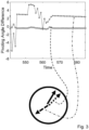
- Figure 3
- is schematic diagram of difference of pivoting angles and corresponding declinations.
- Figure 4
- is a schematic top view of the excavator of
Figure 1 in operation. -
Figure 1 is a schematic side view of anexcavator 1 as an example of a vehicle in the sense of the present disclosure. -
Reference numbers Reference numbers excavator 1, which qualify as an object of the present disclosure. Using the method as described in the present disclosure, at least the orientation or the position of therespective part excavator 1 is determined. - In summary, the schematically drawn excavator allows for the following setups of
gyroscopes objects - The
gyroscope 101a is mounted on awheel 2 guiding acontinuous track 3 of theexcavator 1. Thewheel 2 is rotating about aswivel axis 4. Thegyroscope 101a is used to determine the orientation and position of thechassis 102a of theexcavator 1. In order to measure the pivoting angular velocity ωcarousel of thegyroscope 101a anaccelerometer 103a as a second sensor is mounted on thewheel 2. - The
gyroscope 101b is mounted on afirst arm section 102c of amanipulator arm 5. Themanipulator arm 5 comprises thefirst arm section 102c and ashovel 8 as a second arm section). The firstmanipulator arm section 102c is pivotable about aswivel axis 7 relatively to the body 102b of theexcavator 1. Thegyroscope 101b is used to determine the orientation and position of the body 102b of theexcavator 1. In order to measure the pivoting angular velocity ωcarousel of thegyroscope 101b anaccelerometer 103b as a second sensor is mounted at the firstmanipulator arm section 102c. - Furthermore, the
shovel 8 is pivotable about aswivel axis 9 relatively to the firstmanipulator arm section 102c. Thegyroscope 101c is mounted on theshovel 8. During operation theexcavator 1 experiences a pivoting motion about theswivel axis 9 relatively to the firstmanipulator arm section 102c. In order to measure the pivoting angular velocity ωcarousel of thegyroscope 101c anaccelerometer 103c as a second sensor is mounted on theshovel 8. - As an example in the following paragraph determination of a deviation of the body 102b of the
excavator 1 from true north is described. - The processing system takes a measured signal ω from the gyroscope 101, a measured signal a from the
accelerometer 103b and an initial orientation C 0 as input and provides position p and orientation C as output f:
- The processing system allows to estimate the position of the
chassis 102a via constraints due to motion of thewheel 2 and by iterations find best C. Assuming C is direction cosine matrix then derivative of it is
- Once the effect of the Earth rate is minimized, C already contains absolutely referenced orientation information. To clarify why full orientation estimation is possible, one can see that both gravity and Earth rate are observable in the body reference frame, i.e. the reference frame fixed to the
rotating gyroscope 101a andaccelerometer 103a and are known in Earth frame, i.e. the reference frame fixed to Earth/Moon/Mars. Knowing two non-parallel vectors in this way means that full orientation information can be obtained as known in the art, e.g. from page 283, section 10.3.2 "Ground alignment methods" in D. Titterton, J. Weston: Strapdown Inertial Navigation Technology, Second Edition (Progress in Astronautics & Aeronautics), ISBN-13: 9781563476938, January 2005. Earth rate signal effected by the rotation of the Earth causes a slow turn of the vehicle. According to the present disclosure direction of Earth rate signal is estimated by finding a direction in which Earth rate causes least error to the navigation output. If the raw gyroscope signal is processed through inertial navigation algorithm, any constant signal component in it will be modulated to a sinusoid signal in computed acceleration. Examples for quasi constant signal component is a sensor bias caused by MEMS fabrication or Earth rate rotation. From the joint angle mechanics and vehicle wheel dimensions it is known that this sinusoidal signal is not real but is synthetic due to the combined effect of forced rotation of thegyroscope 101a and quasi-stationary components. It is apparent that inertial navigation algorithm is very sensitive to constant offsets. If one looks at, for example, acceleration derived from inertial navigation algorithm and acceleration derived from joint angle mechanics (derived also with inertial sensors, but using angles and vehicle dimensions) one can figure out the component caused by Earth rotation. A minimization process finds an orientation that give the best agreement between angle-derived acceleration and inertial navigation-derived acceleration. This is similar to bias estimation for MEMS based devices as known from the prior art. The difference in acceleration based on inertial computations and dimension-based computations is minimized by trying different absolute orientations. This minimization can either be carried out in position or velocity domain, whichever fits best from a computational point of view. Earth rate determination is much more prone to noise than bias estimation, as Earth rate signal is very weak. However, over a longer period of time one can see a clear difference in acceleration, velocity and/or position derived from wrong absolute orientation. - For the following example it is assumed both accelerometer and gyroscope observe measurements from three non-parallel measurement axes (so called six-degree-of-freedom system).
-
Figure 2 shows pivoting angle ofswivel axis 7 computed using inertial navigation equations known in prior art (e.g. "Local geographic navigation frame mechanization", page 31 in "Ground alignment methods", of D. Titterton, J. Weston: Strapdown Inertial Navigation Technology, Second Edition (Progress in Astronautics & Aeronautics), ISBN-13: 9781563476938, January 2005. Asterisks show the result when incorrect declination is given to the inertial navigation mechanization algorithm. Circles show the result when a better declination estimate is given to the algorithm. The deviation between these two is due to the Earth rate affecting the measurements. Diamonds show the pivoting angle computed by using the position computed by accelerometer (utilizing known dimensions) as external feedback to the inertial navigation mechanization system.Figure 3 shows the difference between incorrect declination and feedback system result (asterisks) and difference between a better declination and feedback system (circles). It can be observed that the difference is smaller with better declination and thus algorithm that aims to minimize this difference solves the declination.Figure 3 shows the corresponding declinations, showing the top-view of the excavator declination with solid arrow depicting true declination and corresponding declinations ofFigure 2 . The method to minimize the difference can be brute force, or preferably a gradient search algorithm or Extended Kalman filter or modern machine learning method. The feedback system can be Extended Kalman filter with position update as known in the art. The position update derived from pivoting angle and vehicle dimensions is then considered as external measurement to the system. Preferably such filter contains state estimation for gyroscope biases and furthermore can be an Extended Kalman filter augmented by a neural network. -
Figure 4 shows a top view of theexcavator 1 ofFigure 1 with trajectory, e.g. position history accumulated from declinations and distance traveled 401. The distance traveled 401 can be derived from known wheel radius and pivoting angles. Another distance traveled 401 can be computed from known dimensions of themanipulator arm 5 and known pivoting angles using vector addition -shovel position 402 with respect to center of the vehicle, for example. Declination is theangle 403 between true north N and object'smain axis 404. - It is noted that features described in connection with one embodiment also can be used in other embodiments as is readily understandable by a person skilled in the art. While the invention has been described in detail and with reference to the Figures, this description is only an example and is not considered to restrict the scope of protection as it is defined by the claims. Known distance or radius can mean knowledge of such measure with mm, cm, meter level, for example.
- In the claims the word "comprising" does not exclude other elements or steps and the undefined article "a" does not exclude a plurality. The mere fact that some features have been claimed in different claims does not exclude their combination. Reference numbers in the claims are not considered to restrict the scope of protection.
-
- 1
- excavator
- 2
- wheel
- 3
- continuous track
- 4, 7, 9
- swivel axis
- 5
- manipulator arm
- 6
- first arm section
- 8
- shovel
- 101a, 101b, 101c
- gyroscope
- 102a
- chassis
- 102b
- body
- 102c
- first arm section
- 103a, 103b, 103c
- accelerometer
- 401
- distance traveled
- 402
- shovel position
- 403
- angle between true north and object's main axis
- 404
- main axis of the object
- ωcarousel
- angular velocity
- N
- true north
Claims (4)
- A method for determining a declination of an object (102a, 102b, 102c), the method comprising the steps of:pivoting a gyroscope (101a, 101b, 101c), which gyroscope (101a, 101b, 101c) is mounted to the object (102a, 102b, 102c), at a pivoting angular velocity (ωcar-ousel) about a swivel axis (4, 7, 9);measuring an undetermined pivoting of the object (102a, 102b, 102c) about an axis with the gyroscope (101a, 101b, 101c), wherein the axis is different from the swivel axis (4, 7, 9);determining a component of the rotation of the Earth acting on the gyroscope (101a, 101b, 101c) usingthe undetermined pivoting, andthe pivoting angular velocity (ωcarousel); anddetermining the declination of the object (102a, 102b, 102c) with respect to true north from the component of the rotation of the Earth acting on the gyroscope (101a, 101b, 101c);wherein the object is a vehicle (1) or a part of a vehicle (102a, 102b, 102c), which vehicle (1) comprises a first vehicle part and a second vehicle part;wherein the first vehicle part is pivotable about the swivel axis (4, 7, 9) relative to the second vehicle part;wherein the gyroscope (101a, 101b, 101c) is mechanically mounted to the first vehicle part; andthe method being characterised by further comprising the step of:
determining the pivoting angular velocity (ωcarousel) of the gyroscope (101a, 101b, 101c) about the swivel axis (4, 7, 9) with a second sensor, which second sensor (103a, 103b, 103c) is distinct from the gyroscope (101a, 101b, 101c) and capable of providing a measurement of the pivoting angular velocity (ωcarousel) that is not affected by Earth rate,wherein the vehicle (1) comprises a manipulator arm (5), wherein the first vehicle part is a first arm section (6) of the manipulator arm (5), and wherein the second vehicle part is a second arm section of the manipulator arm (5) or the second vehicle part is a frame or a body of the vehicle. - The method according to anyone of the previous claims, wherein the second sensor is an acceleration sensor, wherein the acceleration sensor is distanced by a known distance from the swivel axis.
- The method according to anyone of the previous claims, wherein the gyroscope is a microelectromechanical system.
- The method according to anyone of the previous claims as far as dependent on claim 2, wherein the gyroscope and accelerometer form a six degree of freedom measurement system.
Applications Claiming Priority (2)
| Application Number | Priority Date | Filing Date | Title |
|---|---|---|---|
| DE102020118321 | 2020-07-10 | ||
| PCT/EP2021/068286 WO2022008361A2 (en) | 2020-07-10 | 2021-07-02 | Absolute heading estimation with constrained motion |
Publications (4)
| Publication Number | Publication Date |
|---|---|
| EP4179274A2 EP4179274A2 (en) | 2023-05-17 |
| EP4179274C0 EP4179274C0 (en) | 2025-06-25 |
| EP4179274B1 true EP4179274B1 (en) | 2025-06-25 |
| EP4179274B8 EP4179274B8 (en) | 2025-08-13 |
Family
ID=76859612
Family Applications (1)
| Application Number | Title | Priority Date | Filing Date |
|---|---|---|---|
| EP21740005.0A Active EP4179274B8 (en) | 2020-07-10 | 2021-07-02 | Absolute heading estimation with constrained motion |
Country Status (5)
| Country | Link |
|---|---|
| US (1) | US12235109B2 (en) |
| EP (1) | EP4179274B8 (en) |
| JP (1) | JP7761035B2 (en) |
| AU (1) | AU2021304421A1 (en) |
| WO (1) | WO2022008361A2 (en) |
Families Citing this family (3)
| Publication number | Priority date | Publication date | Assignee | Title |
|---|---|---|---|---|
| EP4296434B1 (en) * | 2022-06-22 | 2026-05-06 | Leica Geosystems Technology A/S | Improved determination of an excavator swing boom angle based on intermittent first interim swing boom angles |
| EP4431873A1 (en) * | 2023-03-13 | 2024-09-18 | Leica Geosystems Technology A/S | Sensor chain fusion algorithm |
| JP2025034999A (en) * | 2023-08-31 | 2025-03-13 | 株式会社小松製作所 | Method and device for generating a work vehicle movement amount estimation model |
Citations (1)
| Publication number | Priority date | Publication date | Assignee | Title |
|---|---|---|---|---|
| DE102018200060A1 (en) * | 2018-01-04 | 2019-07-04 | Robert Bosch Gmbh | Method for operating a mobile work machine and mobile work machine |
Family Cites Families (17)
| Publication number | Priority date | Publication date | Assignee | Title |
|---|---|---|---|---|
| US3127774A (en) | 1961-11-08 | 1964-04-07 | North American Aviation Inc | Means and method for determining the direction of the axis of rotation of a controllably rotating platform |
| US4166406A (en) | 1977-09-06 | 1979-09-04 | Litton Systems, Inc. | Self-aligning pitch and azimuth reference unit |
| US4321678A (en) | 1977-09-14 | 1982-03-23 | Bodenseewerk Geratetechnik Gmbh | Apparatus for the automatic determination of a vehicle position |
| DE3229819C2 (en) | 1982-08-11 | 1985-02-14 | Bodenseewerk Gerätetechnik GmbH, 7770 Überlingen | Integrated navigation and fire control system for battle tanks |
| JP2001141507A (en) | 1999-11-11 | 2001-05-25 | Yokogawa Denshikiki Co Ltd | Inertial navigation system |
| JP4586172B2 (en) | 2005-12-07 | 2010-11-24 | 独立行政法人海洋研究開発機構 | Inertial navigation system |
| FR2961305B1 (en) | 2010-06-14 | 2012-06-22 | Eurocopter France | IMPROVED INERTIAL MEASUREMENT DEVICE AND AIRCRAFT COMPRISING SUCH A DEVICE |
| IL209261A0 (en) | 2010-11-11 | 2011-01-31 | Israel Aerospace Ind Ltd | A system and method for north finding |
| EP2578992B1 (en) * | 2011-10-06 | 2017-01-25 | Vectronix AG | Geographical azimuth determination referenced to north |
| FI124697B (en) | 2012-04-04 | 2014-12-15 | Jc Inertial Oy | Positioning of vehicles |
| AU2017232241B1 (en) | 2017-03-31 | 2018-09-20 | Commonwealth Scientific And Industrial Research Organisation | Low Cost INS |
| US20180345533A1 (en) * | 2017-05-31 | 2018-12-06 | Cazza Inc. | Mobile three-dimensional printer with layer smoothing |
| US10586349B2 (en) * | 2017-08-24 | 2020-03-10 | Trimble Inc. | Excavator bucket positioning via mobile device |
| CN111902585A (en) | 2018-03-27 | 2020-11-06 | 住友重机械工业株式会社 | Excavator |
| KR102687696B1 (en) | 2018-10-03 | 2024-07-22 | 스미도모쥬기가이고교 가부시키가이샤 | shovel |
| JP7182458B2 (en) | 2018-12-27 | 2022-12-02 | 日立建機株式会社 | working machine |
| US20210340724A1 (en) * | 2020-05-01 | 2021-11-04 | Deere & Company | Work vehicle magnetorheological fluid joystick systems providing machine state feedback |
-
2021
- 2021-07-02 JP JP2023501374A patent/JP7761035B2/en active Active
- 2021-07-02 AU AU2021304421A patent/AU2021304421A1/en active Pending
- 2021-07-02 EP EP21740005.0A patent/EP4179274B8/en active Active
- 2021-07-02 WO PCT/EP2021/068286 patent/WO2022008361A2/en not_active Ceased
- 2021-07-02 US US18/004,859 patent/US12235109B2/en active Active
Patent Citations (1)
| Publication number | Priority date | Publication date | Assignee | Title |
|---|---|---|---|---|
| DE102018200060A1 (en) * | 2018-01-04 | 2019-07-04 | Robert Bosch Gmbh | Method for operating a mobile work machine and mobile work machine |
Also Published As
| Publication number | Publication date |
|---|---|
| JP7761035B2 (en) | 2025-10-28 |
| US12235109B2 (en) | 2025-02-25 |
| EP4179274C0 (en) | 2025-06-25 |
| CA3189127A1 (en) | 2022-01-13 |
| US20230349699A1 (en) | 2023-11-02 |
| AU2021304421A1 (en) | 2023-03-09 |
| WO2022008361A3 (en) | 2022-03-10 |
| EP4179274A2 (en) | 2023-05-17 |
| EP4179274B8 (en) | 2025-08-13 |
| JP2023533065A (en) | 2023-08-01 |
| WO2022008361A2 (en) | 2022-01-13 |
Similar Documents
| Publication | Publication Date | Title |
|---|---|---|
| JP6094026B2 (en) | Posture determination method, position calculation method, and posture determination apparatus | |
| EP1653194B1 (en) | Azimuth/attitude detecting sensor | |
| Nebot et al. | Initial calibration and alignment of low‐cost inertial navigation units for land vehicle applications | |
| CN101413800B (en) | Navigation and aiming stabilization method of integrated navigation/sighting stabilization system | |
| US6459990B1 (en) | Self-contained positioning method and system thereof for water and land vehicles | |
| US9541392B2 (en) | Surveying system and method | |
| EP2901104B1 (en) | Improved inertial navigation system and method | |
| EP3040680B1 (en) | Magnetic anomaly tracking for an inertial navigation system | |
| Chen et al. | Rapid initial heading alignment for MEMS land vehicular GNSS/INS navigation system | |
| CN113063429B (en) | Self-adaptive vehicle-mounted integrated navigation positioning method | |
| CN105823481A (en) | GNSS-INS vehicle attitude determination method based on single antenna | |
| JP3767372B2 (en) | Satellite tracking antenna controller | |
| US7957898B2 (en) | Computational scheme for MEMS inertial navigation system | |
| US12235109B2 (en) | Absolute heading estimation with constrained motion | |
| WO2018176092A1 (en) | "low cost ins" | |
| CN112880669A (en) | Spacecraft starlight refraction and uniaxial rotation modulation inertia combined navigation method | |
| JPH095104A (en) | Three-dimensional attitude angle measuring method and three-dimensional attitude angle measuring device for moving objects | |
| US9217639B1 (en) | North-finding using inertial navigation system | |
| WO2013139486A1 (en) | True north seeking and attitude system | |
| CA3189127C (en) | Absolute heading estimation with constrained motion | |
| CN109596139B (en) | MEMS-based vehicle navigation method | |
| CN111141283A (en) | Method for judging advancing direction through geomagnetic data | |
| AU2020220232A1 (en) | An inertial measurement unit and method of operation | |
| CN117723054A (en) | Positioning method of integrated anchor digger based on strapdown inertial navigation and binocular visual displacement information fusion | |
| Ojeda et al. | Improved position estimation for mobile robots on rough terrain using attitude information |
Legal Events
| Date | Code | Title | Description |
|---|---|---|---|
| STAA | Information on the status of an ep patent application or granted ep patent |
Free format text: STATUS: UNKNOWN |
|
| STAA | Information on the status of an ep patent application or granted ep patent |
Free format text: STATUS: THE INTERNATIONAL PUBLICATION HAS BEEN MADE |
|
| PUAI | Public reference made under article 153(3) epc to a published international application that has entered the european phase |
Free format text: ORIGINAL CODE: 0009012 |
|
| STAA | Information on the status of an ep patent application or granted ep patent |
Free format text: STATUS: REQUEST FOR EXAMINATION WAS MADE |
|
| 17P | Request for examination filed |
Effective date: 20230203 |
|
| AK | Designated contracting states |
Kind code of ref document: A2 Designated state(s): AL AT BE BG CH CY CZ DE DK EE ES FI FR GB GR HR HU IE IS IT LI LT LU LV MC MK MT NL NO PL PT RO RS SE SI SK SM TR |
|
| DAV | Request for validation of the european patent (deleted) | ||
| DAX | Request for extension of the european patent (deleted) | ||
| RIC1 | Information provided on ipc code assigned before grant |
Ipc: E02F 9/26 20060101ALI20241128BHEP Ipc: E02F 9/20 20060101ALI20241128BHEP Ipc: E02F 3/43 20060101ALI20241128BHEP Ipc: E02F 3/84 20060101ALI20241128BHEP Ipc: G01C 21/16 20060101ALI20241128BHEP Ipc: G01C 19/38 20060101AFI20241128BHEP |
|
| GRAP | Despatch of communication of intention to grant a patent |
Free format text: ORIGINAL CODE: EPIDOSNIGR1 |
|
| STAA | Information on the status of an ep patent application or granted ep patent |
Free format text: STATUS: GRANT OF PATENT IS INTENDED |
|
| INTG | Intention to grant announced |
Effective date: 20250122 |
|
| GRAS | Grant fee paid |
Free format text: ORIGINAL CODE: EPIDOSNIGR3 |
|
| GRAA | (expected) grant |
Free format text: ORIGINAL CODE: 0009210 |
|
| STAA | Information on the status of an ep patent application or granted ep patent |
Free format text: STATUS: THE PATENT HAS BEEN GRANTED |
|
| REG | Reference to a national code |
Ref country code: DE Ref legal event code: R081 Ref document number: 602021032876 Country of ref document: DE Owner name: NORDIC INERTIAL OY, FI Free format text: FORMER OWNER: NORDIC INERTIAL OY, AKAA, FI |
|
| AK | Designated contracting states |
Kind code of ref document: B1 Designated state(s): AL AT BE BG CH CY CZ DE DK EE ES FI FR GB GR HR HU IE IS IT LI LT LU LV MC MK MT NL NO PL PT RO RS SE SI SK SM TR |
|
| REG | Reference to a national code |
Ref country code: GB Ref legal event code: FG4D |
|
| REG | Reference to a national code |
Ref country code: CH Ref legal event code: EP |
|
| RAP4 | Party data changed (patent owner data changed or rights of a patent transferred) |
Owner name: NORDIC INERTIAL OY |
|
| REG | Reference to a national code |
Ref country code: CH Ref legal event code: EP |
|
| REG | Reference to a national code |
Ref country code: IE Ref legal event code: FG4D |
|
| REG | Reference to a national code |
Ref country code: DE Ref legal event code: R096 Ref document number: 602021032876 Country of ref document: DE |
|
| REG | Reference to a national code |
Ref country code: CH Ref legal event code: PK Free format text: BERICHTIGUNG B8 |
|
| U01 | Request for unitary effect filed |
Effective date: 20250708 |
|
| U07 | Unitary effect registered |
Designated state(s): AT BE BG DE DK EE FI FR IT LT LU LV MT NL PT RO SE SI Effective date: 20250714 |
|
| U20 | Renewal fee for the european patent with unitary effect paid |
Year of fee payment: 5 Effective date: 20250716 |
|
| PG25 | Lapsed in a contracting state [announced via postgrant information from national office to epo] |
Ref country code: NO Free format text: LAPSE BECAUSE OF FAILURE TO SUBMIT A TRANSLATION OF THE DESCRIPTION OR TO PAY THE FEE WITHIN THE PRESCRIBED TIME-LIMIT Effective date: 20250925 Ref country code: GR Free format text: LAPSE BECAUSE OF FAILURE TO SUBMIT A TRANSLATION OF THE DESCRIPTION OR TO PAY THE FEE WITHIN THE PRESCRIBED TIME-LIMIT Effective date: 20250926 |
|
| PGFP | Annual fee paid to national office [announced via postgrant information from national office to epo] |
Ref country code: GB Payment date: 20250724 Year of fee payment: 5 |
|
| PG25 | Lapsed in a contracting state [announced via postgrant information from national office to epo] |
Ref country code: HR Free format text: LAPSE BECAUSE OF FAILURE TO SUBMIT A TRANSLATION OF THE DESCRIPTION OR TO PAY THE FEE WITHIN THE PRESCRIBED TIME-LIMIT Effective date: 20250625 |
|
| PG25 | Lapsed in a contracting state [announced via postgrant information from national office to epo] |
Ref country code: RS Free format text: LAPSE BECAUSE OF FAILURE TO SUBMIT A TRANSLATION OF THE DESCRIPTION OR TO PAY THE FEE WITHIN THE PRESCRIBED TIME-LIMIT Effective date: 20250925 |
|
| PG25 | Lapsed in a contracting state [announced via postgrant information from national office to epo] |
Ref country code: IS Free format text: LAPSE BECAUSE OF FAILURE TO SUBMIT A TRANSLATION OF THE DESCRIPTION OR TO PAY THE FEE WITHIN THE PRESCRIBED TIME-LIMIT Effective date: 20251025 |
|
| PG25 | Lapsed in a contracting state [announced via postgrant information from national office to epo] |
Ref country code: SM Free format text: LAPSE BECAUSE OF FAILURE TO SUBMIT A TRANSLATION OF THE DESCRIPTION OR TO PAY THE FEE WITHIN THE PRESCRIBED TIME-LIMIT Effective date: 20250625 |
|
| PG25 | Lapsed in a contracting state [announced via postgrant information from national office to epo] |
Ref country code: CZ Free format text: LAPSE BECAUSE OF FAILURE TO SUBMIT A TRANSLATION OF THE DESCRIPTION OR TO PAY THE FEE WITHIN THE PRESCRIBED TIME-LIMIT Effective date: 20250625 |
|
| PG25 | Lapsed in a contracting state [announced via postgrant information from national office to epo] |
Ref country code: PL Free format text: LAPSE BECAUSE OF FAILURE TO SUBMIT A TRANSLATION OF THE DESCRIPTION OR TO PAY THE FEE WITHIN THE PRESCRIBED TIME-LIMIT Effective date: 20250625 |
|
| PG25 | Lapsed in a contracting state [announced via postgrant information from national office to epo] |
Ref country code: SK Free format text: LAPSE BECAUSE OF FAILURE TO SUBMIT A TRANSLATION OF THE DESCRIPTION OR TO PAY THE FEE WITHIN THE PRESCRIBED TIME-LIMIT Effective date: 20250625 |
|
| PG25 | Lapsed in a contracting state [announced via postgrant information from national office to epo] |
Ref country code: ES Free format text: LAPSE BECAUSE OF FAILURE TO SUBMIT A TRANSLATION OF THE DESCRIPTION OR TO PAY THE FEE WITHIN THE PRESCRIBED TIME-LIMIT Effective date: 20250625 |
|
| REG | Reference to a national code |
Ref country code: CH Ref legal event code: H13 Free format text: ST27 STATUS EVENT CODE: U-0-0-H10-H13 (AS PROVIDED BY THE NATIONAL OFFICE) Effective date: 20260224 |
|
| PG25 | Lapsed in a contracting state [announced via postgrant information from national office to epo] |
Ref country code: MC Free format text: LAPSE BECAUSE OF FAILURE TO SUBMIT A TRANSLATION OF THE DESCRIPTION OR TO PAY THE FEE WITHIN THE PRESCRIBED TIME-LIMIT Effective date: 20250625 |
|
| PG25 | Lapsed in a contracting state [announced via postgrant information from national office to epo] |
Ref country code: CH Free format text: LAPSE BECAUSE OF NON-PAYMENT OF DUE FEES Effective date: 20250731 |
|
| PLBE | No opposition filed within time limit |
Free format text: ORIGINAL CODE: 0009261 |
|
| STAA | Information on the status of an ep patent application or granted ep patent |
Free format text: STATUS: NO OPPOSITION FILED WITHIN TIME LIMIT |
|
| REG | Reference to a national code |
Ref country code: CH Ref legal event code: L10 Free format text: ST27 STATUS EVENT CODE: U-0-0-L10-L00 (AS PROVIDED BY THE NATIONAL OFFICE) Effective date: 20260507 |