EP4178830B1 - Stability rollers for a long rail assembly - Google Patents
Stability rollers for a long rail assembly Download PDFInfo
- Publication number
- EP4178830B1 EP4178830B1 EP21806434.3A EP21806434A EP4178830B1 EP 4178830 B1 EP4178830 B1 EP 4178830B1 EP 21806434 A EP21806434 A EP 21806434A EP 4178830 B1 EP4178830 B1 EP 4178830B1
- Authority
- EP
- European Patent Office
- Prior art keywords
- rail
- long rail
- wing bracket
- assembly
- flexible
- Prior art date
- Legal status (The legal status is an assumption and is not a legal conclusion. Google has not performed a legal analysis and makes no representation as to the accuracy of the status listed.)
- Active
Links
Images





Classifications
-
- B—PERFORMING OPERATIONS; TRANSPORTING
- B60—VEHICLES IN GENERAL
- B60N—SEATS SPECIALLY ADAPTED FOR VEHICLES; VEHICLE PASSENGER ACCOMMODATION NOT OTHERWISE PROVIDED FOR
- B60N2/00—Seats specially adapted for vehicles; Arrangement or mounting of seats in vehicles
- B60N2/02—Seats specially adapted for vehicles; Arrangement or mounting of seats in vehicles the seat or part thereof being movable, e.g. adjustable
- B60N2/04—Seats specially adapted for vehicles; Arrangement or mounting of seats in vehicles the seat or part thereof being movable, e.g. adjustable the whole seat being movable
- B60N2/06—Seats specially adapted for vehicles; Arrangement or mounting of seats in vehicles the seat or part thereof being movable, e.g. adjustable the whole seat being movable slidable
- B60N2/07—Slide construction
- B60N2/0722—Constructive details
-
- B—PERFORMING OPERATIONS; TRANSPORTING
- B60—VEHICLES IN GENERAL
- B60N—SEATS SPECIALLY ADAPTED FOR VEHICLES; VEHICLE PASSENGER ACCOMMODATION NOT OTHERWISE PROVIDED FOR
- B60N2/00—Seats specially adapted for vehicles; Arrangement or mounting of seats in vehicles
- B60N2/02—Seats specially adapted for vehicles; Arrangement or mounting of seats in vehicles the seat or part thereof being movable, e.g. adjustable
- B60N2/04—Seats specially adapted for vehicles; Arrangement or mounting of seats in vehicles the seat or part thereof being movable, e.g. adjustable the whole seat being movable
- B60N2/06—Seats specially adapted for vehicles; Arrangement or mounting of seats in vehicles the seat or part thereof being movable, e.g. adjustable the whole seat being movable slidable
-
- B—PERFORMING OPERATIONS; TRANSPORTING
- B60—VEHICLES IN GENERAL
- B60N—SEATS SPECIALLY ADAPTED FOR VEHICLES; VEHICLE PASSENGER ACCOMMODATION NOT OTHERWISE PROVIDED FOR
- B60N2/00—Seats specially adapted for vehicles; Arrangement or mounting of seats in vehicles
- B60N2/02—Seats specially adapted for vehicles; Arrangement or mounting of seats in vehicles the seat or part thereof being movable, e.g. adjustable
- B60N2/04—Seats specially adapted for vehicles; Arrangement or mounting of seats in vehicles the seat or part thereof being movable, e.g. adjustable the whole seat being movable
- B60N2/06—Seats specially adapted for vehicles; Arrangement or mounting of seats in vehicles the seat or part thereof being movable, e.g. adjustable the whole seat being movable slidable
- B60N2/065—Rear seats
-
- B—PERFORMING OPERATIONS; TRANSPORTING
- B60—VEHICLES IN GENERAL
- B60N—SEATS SPECIALLY ADAPTED FOR VEHICLES; VEHICLE PASSENGER ACCOMMODATION NOT OTHERWISE PROVIDED FOR
- B60N2/00—Seats specially adapted for vehicles; Arrangement or mounting of seats in vehicles
- B60N2/02—Seats specially adapted for vehicles; Arrangement or mounting of seats in vehicles the seat or part thereof being movable, e.g. adjustable
- B60N2/04—Seats specially adapted for vehicles; Arrangement or mounting of seats in vehicles the seat or part thereof being movable, e.g. adjustable the whole seat being movable
- B60N2/06—Seats specially adapted for vehicles; Arrangement or mounting of seats in vehicles the seat or part thereof being movable, e.g. adjustable the whole seat being movable slidable
- B60N2/07—Slide construction
-
- B—PERFORMING OPERATIONS; TRANSPORTING
- B60—VEHICLES IN GENERAL
- B60N—SEATS SPECIALLY ADAPTED FOR VEHICLES; VEHICLE PASSENGER ACCOMMODATION NOT OTHERWISE PROVIDED FOR
- B60N2/00—Seats specially adapted for vehicles; Arrangement or mounting of seats in vehicles
- B60N2/02—Seats specially adapted for vehicles; Arrangement or mounting of seats in vehicles the seat or part thereof being movable, e.g. adjustable
- B60N2/04—Seats specially adapted for vehicles; Arrangement or mounting of seats in vehicles the seat or part thereof being movable, e.g. adjustable the whole seat being movable
- B60N2/06—Seats specially adapted for vehicles; Arrangement or mounting of seats in vehicles the seat or part thereof being movable, e.g. adjustable the whole seat being movable slidable
- B60N2/07—Slide construction
- B60N2/0702—Slide construction characterised by its cross-section
- B60N2/0705—Slide construction characterised by its cross-section omega-shaped
-
- B—PERFORMING OPERATIONS; TRANSPORTING
- B60—VEHICLES IN GENERAL
- B60N—SEATS SPECIALLY ADAPTED FOR VEHICLES; VEHICLE PASSENGER ACCOMMODATION NOT OTHERWISE PROVIDED FOR
- B60N2/00—Seats specially adapted for vehicles; Arrangement or mounting of seats in vehicles
- B60N2/02—Seats specially adapted for vehicles; Arrangement or mounting of seats in vehicles the seat or part thereof being movable, e.g. adjustable
- B60N2/04—Seats specially adapted for vehicles; Arrangement or mounting of seats in vehicles the seat or part thereof being movable, e.g. adjustable the whole seat being movable
- B60N2/06—Seats specially adapted for vehicles; Arrangement or mounting of seats in vehicles the seat or part thereof being movable, e.g. adjustable the whole seat being movable slidable
- B60N2/07—Slide construction
- B60N2/0702—Slide construction characterised by its cross-section
- B60N2/0715—C or U-shaped
-
- B—PERFORMING OPERATIONS; TRANSPORTING
- B60—VEHICLES IN GENERAL
- B60N—SEATS SPECIALLY ADAPTED FOR VEHICLES; VEHICLE PASSENGER ACCOMMODATION NOT OTHERWISE PROVIDED FOR
- B60N2205/00—General mechanical or structural details
- B60N2205/20—Measures for elimination or compensation of play or backlash
Definitions
- the present invention relates to a rail drive assembly that supports a vehicle seat and is configured to travel along a fixed long rail when the vehicle seat is repositioned to another location along the fixed long rail. More particularly, the invention relates to a long rail drive assembly having a flexible stability roller assembly to absorb both vertical and lateral channel variation.
- Various slide mechanisms having stability rolling elements are known for repositioning a vehicle seat along a long rail in a vehicle.
- One known seat sliding device is disclosed in W.O. Publication 2020/077209 wherein a vehicle seat is coupled to a rail drive assembly that is slidable within a fixed long rail.
- the rail drive assembly includes wheels configured to travel along an interior track of the fixed long rail.
- stability rolling elements are mounted at an angle to side walls of the rail drive assembly. Front and rear stability rolling elements on each side of the rail drive assembly are operationally coupled by a torsion spring extending in a longitudinal direction.
- this known seat sliding device lacks spring-loaded stability rollers that are spring-loaded in both lateral and vertical directions to absorb channel variations.
- the stability rolling elements of this known seat sliding device includes a plurality of components which can be difficult to assemble.
- this exemplary known seat sliding device lacks spring-loaded stability rolling elements that act as a compression spring to resist lateral load applied to the vehicle seat.
- WO 2020/186259 A1 discloses a long rail assembly for use in a vehicle includes a lower channel, an inverted U-shaped upper channel, a gearbox, a rack, a pinion, a drive shaft, and a motor.
- the lower channel is adapted to extend longitudinally along a floor of the vehicle.
- the upper channel is slidably coupled to the lower channel.
- the gearbox is fixedly secured to and housed within the upper channel.
- the rack is fixedly coupled to the lower channel and includes gear teeth extending along the rack in a longitudinal direction.
- the pinion is meshingly engaged with the gear teeth.
- the drive shaft operatively couples the gearbox to the pinion.
- the motor is operatively coupled to the gearbox to power drive the upper channel along the lower channel.
- a rail drive assembly it is desirable, therefore, for a rail drive assembly to have a stability roller assembly that is easy to assemble. Further, it is desirable to reduce the number of components in the stability roller assembly. In addition, it is desirable for the stability roller assembly to resist fore-aft load applied to the vehicle seat. It is also desirable that the stability roller assembly can act like a compression spring to resist lateral load applied to the vehicle seat. Finally, it is desirable for the rail drive assembly to have a stability roller assembly that absorbs both vertical and lateral channel and positional variation.
- the present invention is a rail drive assembly comprising the technical features as defined in claim 1.
- Figures 1-6 illustrate a long rail assembly 10 having a rail drive assembly 12 configured to transpose the rail drive assembly 12 along a fixed long rail 14 for vehicle seat adjustment according to embodiments described herein.
- Directional references employed or shown in the description, figures or claims, such as top, bottom, upper, lower, upward, downward, lengthwise, widthwise, left, right, and the like, are relative terms employed for ease of description and are not intended to limit the scope of the invention in any respect.
- like numerals indicate like or corresponding parts throughout the several views.
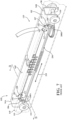
- Figure 1 illustrates a long rail assembly 10 having a rail drive assembly 12 for adjusting a position of a vehicle seat 18 along a fixed long rail 14 according to one embodiment of the present invention.
- Figure 2 shows a vehicle interior 16 having a plurality of vehicle seats 18 connected to rail drive assemblies 12 attached to a vehicle floor 20.
- a cross-sectional view of the long rail assembly 10 of Figure 1 taken along section line A-A is shown in Figure 3 .
- each vehicle seat 18 is supported by at least one leg 28 on opposing sides 18A, 18B of the vehicle seat 18, and optionally front and rear legs 30, 28 on the opposing sides 18A, 18B of the vehicle seat 18.
- Each rail drive assembly 12 travels along one of the fixed long rails 14 attached to the vehicle floor 20.
- Each vehicle seat 18 travels along a pair of fixed long rails 14, 14' when the vehicle seat 18 is repositioned between a first seat location 40 and a second seat location 42, shown as vehicle seat 18' attached to rail drive assembly 12'.
- the fixed long rails 14 can extend for any length suitable for an intended application. Likewise, any suitable number of fixed long rails 14 can be positioned on the vehicle floor 20 as desired for an intended application.
- the long rail assembly 10 allows for improved vehicle seat 18 position adjustment since the vehicle seat 18 coupled to at least one rail drive assembly 12 is repositionable to any seat position 40, 42 along the at least one fixed long rail 14.
- the rail drive assembly 12 is a manual rail drive assembly that is manually repositioned along the fixed long rail 14.
- the rail drive assembly 12 is a power rail drive assembly configured to be automatically repositioned along the fixed long rail 14.
- the fixed long rail 14 has a generally U-shaped cross-section 46 in profile extending in a longitudinal direction, a bottom wall 50, opposing first and second side walls 60, 64, an interior cavity 68, and a top wall 70 having an elongated opening 72 extending in a longitudinal direction. Extending between each one of the first and second side walls 60, 64 and terminating at the adjacent top wall 70 is an upper side wall 74, 78. The first and second upper side walls 74, 78 extend at an angle from the adjacent side wall 60, 64.
- the fixed long rail 14 is a stamped, formed, molded, and/or rolled section of metal, plastic, or combinations of metal and plastic materials and has a length selected based on a specific application.
- the size and shape of the fixed long rail 14 may vary without altering the scope of the invention.
- the dimensions of the fixed long rail 14, including the cross-sectional profile 46, are selected, in part, based on generally known engineering calculations, finite element analysis (FEA), and physical testing.
- the rail drive assembly 12 includes an elongated upper channel 94 having a generally W-shape cross-section 96 in profile, opposing first and second side walls 98, 100 and a top wall 102 extending between the opposing first and second side walls 98, 100.
- An axle 106 extends laterally through a hollow tube 108 extending between the opposing side walls 98, 100.
- a wheel 110 is fixedly coupled to each end 106A of the axle 106.
- the rail drive assembly 12 shown in the embodiment of Figure 1 includes a pair of wheels 110 positioned adjacent to opposing ends 94A, 94B of the upper channel 94. While not shown, the wheels 110 can be replaced by rollers and/or glides.
- each wheel 110 or roller can be rotationally attached to the upper channel 94 using a shaft (not shown) fixedly coupled to one of the side walls 98, 100 of the upper channel 94.
- each pair of wheels 110 is attached to carrier 112 having a generally inverted U-shape cross-section in profile.
- the carrier 112 includes an upper wall 112A extending between opposing first and second side walls 112B, 112C.
- the axle 106 passes through a hole 112D in each of the opposing first and second side walls 112B, 112C.
- the carrier 112 is fixedly coupled to the upper channel 94.
- the rail drive assembly 12 includes spaced apart first and second flexible stability roller assemblies 116, 116'.
- Each of the first and second flexible stability roller assemblies 116, 116' is positioned near a respective end 94A, 94B of the upper channel 94.
- the flexible stability roller assemblies 116, 116' are fixedly coupled to a lower side 102A of the top wall 102 of the upper channel 94.
- Each flexible stability roller assembly 116, 116' includes first and second stability rollers 118A, 118B rotationally coupled to a flexible wing bracket 120.
- a center portion 120A of the flexible wing bracket 120 is welded to the upper channel 94 in two spaced apart locations 124A, 124B.
- the flexible wing bracket 120 is welded to the upper channel 94 in one location 124A, 124B. It will be understood that the flexible wing bracket 120 can be fixedly coupled to the upper channel 94 through other known methods including but not limited to a mechanical fastener, crimping, welding, and press fit.
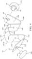
- the flexible wing bracket 120 is shown removed from the rail drive assembly 12 in Figure 4 .
- the flexible wing bracket 120 is a flexible bracket formed out of a metal material such as high strength low alloy (HSLA) steel.
- HSLA high strength low alloy
- SAE Society of Automotive Engineers
- the flexible wing bracket 120 has a general W-shape with opposing first and second side portions 120B, 120C extending from the center portion120A.
- Each of opposing first and second wing portions 120D, 120E extend from the adjacent first and second side portions 120B, 120C.
- each of the first and second side portions 120B, 120C are connected to the center portion 120A by a first curved portion 120F.
- the first and second wing portions 120D, 120C are connected to the adjacent side portions 120B, 120C by a second curved portion 120G.
- the flexible wing bracket 120 has an unconstrained profile 128 (i.e., a "free" profile) in Figure 4 .
- the first and second side portions 120B, 120C project from the center portion 120A an angle 132 of about ninety degrees.
- the specific size, shape, and orientation of the center portion 120A and the first and second side portions 120B, 120C are selected to fit within the upper channel 94. As such, the size, shape, and orientation of the center portion 120A and the first and second side portions 120B, 120C will vary to fit alternate embodiments of the upper channel 94.
- first and second wing portions 120D, 120E project away from the adjacent first and second side portions 120B, 120C at an angle 136 of about forty degrees.
- angle 136 between the first and second wing portions 120D, 120E and the adjacent first and second side portions 120B, 120C can vary in alternate embodiments.
- the unconstrained angle 136 between the first and second wing portions 120D, 120E and the adjacent first and second side portions 120B, 120C is selected to be between thirty degrees and fifty degrees, as a non-limiting example. It will be understood that the unconstrained angle 136 is selected based in part on the specific profile and dimensions of the fixed long rail 14.
- the flexible wing bracket 120 has a longitudinal length between opposing first and second end surfaces 140A, 140B of about 23 mm.
- the exemplary flexible wing bracket 120 has a thickness of about 1 mm as measured between opposing first and second surfaces 142A, 142B of the center portion 120A. It will be understood that the longitudinal length of the flexible wing bracket 120 between the first and second end surfaces 140A, 140B can vary without altering the scope of the invention. Likewise, the thickness of the flexible wing bracket 120 between opposing first and second surfaces 142A, 142B can vary without altering the scope of the invention.
- the flexible wing bracket 120 is alternatively formed out of sheet stock that has been stamped, molded, formed, and/or bent, as non-limiting examples, into the desired shape.
- Each of the first and second wing portions 120D, 120E includes an aperture 148 positioned near a distal end 150 of the first and second wing portions 120D, 120E and extending between the opposing first and second surfaces 142A, 142B, as shown in Figure 4 .
- the aperture 148 is sized and shaped to matingly engage with a shaft 152 extending from the stability roller 118A, 118B.
- the stability rollers 118A, 118B are optionally rotationally coupled to the associated shaft 152 with the associated shaft 152 being fixedly coupled to the flexible wing bracket 120.
- the shaft 152 is rotationally coupled to the flexible wing bracket 120 with the stability roller 118A, 118B being fixedly coupled to the shaft 152.
- a washer 158 is assembled between the flexible wing bracket 120 and the stability roller 118A, 118B.
- the washer 158 is fixedly coupled to the shaft 152, fixedly coupled to the stability roller 118A, 118B, or is a separate component assembled onto the shaft 152.
- the flexible stability roller assembly 116, 116' is shown assembled with the upper channel 94 in Figure 5 .
- the stability rollers 118A, 118B are shown assembled with the flexible wing bracket 120.
- the flexible wing bracket 120 is sized and shaped such that distal ends 162 of the stability rollers 118A, 118B have a designed interference with the fixed long rail 14. More specifically, the distal ends 162 of the stability rollers 118A, 118B extend beyond at least the inner surface 74A, 78A of the upper side walls 74, 78 when the flexible wing bracket 120 is unconstrained.
- Figure 6 shows the flexible stability roller assembly 116, 116' assembled with the fixed long rail 14.
- a comparison of the unconstrained profile 128 and the constrained profile 128' of the flexible wing bracket 120 is shown in Figure 6 . Since the unconstrained profile 128 of the flexible wing bracket 120 has a designed interference with the fixed long rail 14, each of the distal ends 162 of the stability rollers 118A, 118B are pressed inward and downward, as represented by arrow 166, during assembly with the fixed long rail 14. In addition, each of the first and second side portions 120B, 120C of the flexible wing bracket 120 are deflected inward, as illustrated by arrow 168.
- the flexing of the flexible wing bracket 120 moves the distal end 162 of the unconstrained profile 128 to abut the inner surface 74A, 78A of the upper side walls 74, 78, as illustrated by distal end 162' of the constrained profile 128'. Since the flexible wing bracket 120 is flexible and essentially acts as a spring, the flexible wing bracket 120 can accommodate for variation in the dimensions of the fixed long rail 14 as well as accommodating for variation within the rail drive assembly 12.
- the elastic deformation of the flexible wing bracket 120 absorbs channel variation in both up-down and cross-car directions. The elastic deformation during assembly can provide reaction force to the stability rollers 118A, 118B.
- the reaction force from the flexible wing bracket 120 can provide resistance to both up-down and cross-car variation from the rail drive assembly 12.
- the elastic deformation of the flexible wing bracket 120 during assembly with the fixed long rail 14 acts as a compression spring to resist lateral load applied to the vehicle seat 18.
- the flexible wing bracket 120 assists with centering the rail drive assembly 12 within the fixed long rail 14 since the flexible wing bracket 120 maintains a spring bias holding the stability rollers 118A, 118B against the upper side walls 74, 78 of the fixed long rail 14.
- the known long rail assembly 10P includes a known rail drive assembly 12P configured to travel along a fixed long rail 14P.
- the known rail drive assembly 12P includes an upper channel 94 having opposing side walls 98, 100 extending from a top wall 102 forming an inverted U-shape and extending between opposing ends 94A, 94B of the upper channel 94.
- Wheels 110 are rotationally coupled to the upper channel 94 near each end 94A, 94B of the upper channel 94.
- the fixed long rail 14P is generally U-shaped with opposing side walls 60, 64 extending between a bottom wall 50 and a top wall 70 of the fixed long rail 14P. Extending between each side wall 60, 64 and the adjacent top wall 70 is a curved portion 198 having a large corner radius 196.
- each stability rolling element 181, 182 is rotationally coupled to each side wall 98, 100 of the upper channel 94P.
- Figure 8 is a cross-sectional end view taken along section B-B of Figure 7 showing the stability rolling elements 181, 182 being mounted at an angle 183 of about thirty degrees to the side walls 98, 100 of the upper channel 94P.
- Each stability rolling element 181, 182 includes a roller 184, an upper arm 186, 187, a lower arm 188, 189, and a support stud 192.
- Each roller 184 is rotationally coupled to the associated upper arm 186, 187.
- Each upper arm 186, 187 is rotationally coupled to the associated support stud 192.
- Each support stud 192 is fixedly coupled to the adjacent side wall 98, 100 at a mounting angle 183, such as about 30 degrees as shown in Figure 8 .
- the upper arm 187 is fixedly coupled to the lower arm 189 so they are linked together to move as one arm.
- a first end 208A of a torsion spring 208 is connected to the lower arm 188 of the known first stability rolling element 181.
- a second end 208B of the torsion spring 208 is connected to the lower arm 189 of the known second stability rolling element 182.
- the torsion spring 208 biases the rollers 184 of the stability rolling elements 181, 182 towards the adjacent fixed long rail 14P curved portions 198.
- the torsion spring 208 induces a longitudinal spring bias into the stability rolling elements 181, 182, as illustrated by arrow 210 shown in Figure 7 .
- the known stability rolling elements 181, 182 can rotate with respect to the associated pivot shaft 192, as illustrated by arrows 212.
- the roller 184 absorbs variations in both a lateral and a vertical directions of the fixed long rail 14 since the roller 184 is angled at about 30 degrees from the side walls 100, 98 of the upper channel 94.
- the stability rolling elements 181, 182 of the known long rail assembly 12P shown in Figures 7 and 8 require a plurality of parts, including the upper arm 186, 187, the lower arm 188, 189, the support stud 192, and the torsion spring 208. In the embodiment shown in Figures 1-6 , these components have been replaced by a single flexible wing bracket 120. The reduction in the number of components directly reduces the cost and complexity of the long rail assembly 12 in comparison to the known long rail assembly 12P.
- assembly of the flexible wing bracket 120 with the fixed long rail 14 induces a lateral spring bias load into the flexible wing bracket 120, as illustrated by arrow 220 shown in Figure 6 .
- the torsion spring 208 of the known long rail assembly 12P induces a longitudinal spring bias 210 into the stability rolling elements 181, 182.
- the known long rail assembly 12P relies on the upper arms 186, 187 being oriented at about a thirty degree angle with respect to the adjacent side wall 98, 100 of the upper channel 94 in combination with the curved portion 198 of the side walls 60, 64 of the fixed long rail 14P to laterally bias the stability rolling elements 181, 182 towards the side walls 60, 64 of the fixed long rail 14P.
- the flexible wing bracket 120 of the embodiment shown in Figures 1-6 actively spring biases the stability rollers 118A, 118B towards the adjacent upper side wall 74, 78 of the fixed long rail 14. As such, the flexible wing bracket 120 actively laterally stabilizes the upper channel 94 within the fixed long rail 14.
- a rail drive assembly 12 for a long rail assembly 10 having a flexible stability roller assembly 116, 116' is the flexible stability roller assembly 116, 116' is easy to assemble since there are few components.
- a second benefit of the flexible stability roller assembly 116, 116' is the cost is reduced in comparison to other known spring-loaded stability rollers since the number of components has been reduced.
- a third benefit is the flexible stability roller assembly 116, 116' can act like a compression spring to resist lateral load applied to the vehicle seat 18.
- a fourth benefit is the flexible stability roller assembly 116, 116' can absorb both vertical and lateral channel and positional variation.
Landscapes
- Engineering & Computer Science (AREA)
- Aviation & Aerospace Engineering (AREA)
- Transportation (AREA)
- Mechanical Engineering (AREA)
- Seats For Vehicles (AREA)
- Bearings For Parts Moving Linearly (AREA)
Description
- The present invention relates to a rail drive assembly that supports a vehicle seat and is configured to travel along a fixed long rail when the vehicle seat is repositioned to another location along the fixed long rail. More particularly, the invention relates to a long rail drive assembly having a flexible stability roller assembly to absorb both vertical and lateral channel variation.
- Various slide mechanisms having stability rolling elements are known for repositioning a vehicle seat along a long rail in a vehicle. One known seat sliding device is disclosed in W.O. Publication
2020/077209 wherein a vehicle seat is coupled to a rail drive assembly that is slidable within a fixed long rail. The rail drive assembly includes wheels configured to travel along an interior track of the fixed long rail. In addition, stability rolling elements are mounted at an angle to side walls of the rail drive assembly. Front and rear stability rolling elements on each side of the rail drive assembly are operationally coupled by a torsion spring extending in a longitudinal direction. - However, this known seat sliding device lacks spring-loaded stability rollers that are spring-loaded in both lateral and vertical directions to absorb channel variations. In addition, the stability rolling elements of this known seat sliding device includes a plurality of components which can be difficult to assemble. Finally, this exemplary known seat sliding device lacks spring-loaded stability rolling elements that act as a compression spring to resist lateral load applied to the vehicle seat.
-
WO 2020/186259 A1 discloses a long rail assembly for use in a vehicle includes a lower channel, an inverted U-shaped upper channel, a gearbox, a rack, a pinion, a drive shaft, and a motor. The lower channel is adapted to extend longitudinally along a floor of the vehicle. The upper channel is slidably coupled to the lower channel. The gearbox is fixedly secured to and housed within the upper channel. The rack is fixedly coupled to the lower channel and includes gear teeth extending along the rack in a longitudinal direction. The pinion is meshingly engaged with the gear teeth. The drive shaft operatively couples the gearbox to the pinion. The motor is operatively coupled to the gearbox to power drive the upper channel along the lower channel. - It is desirable, therefore, for a rail drive assembly to have a stability roller assembly that is easy to assemble. Further, it is desirable to reduce the number of components in the stability roller assembly. In addition, it is desirable for the stability roller assembly to resist fore-aft load applied to the vehicle seat. It is also desirable that the stability roller assembly can act like a compression spring to resist lateral load applied to the vehicle seat. Finally, it is desirable for the rail drive assembly to have a stability roller assembly that absorbs both vertical and lateral channel and positional variation.
- The present invention is a rail drive assembly comprising the technical features as defined in
claim 1. - Advantages of the present invention will be readily appreciated as the same becomes better understood by reference to the following detailed description when considered in connection with the accompanying drawings wherein:
-
Figure 1 is a cutaway perspective view of a portion of a long rail assembly including a rail drive assembly having stability rollers connected by a flexible wing bracket, according to one embodiment of the present invention; -
Figure 2 is a perspective view of a vehicle interior and having vehicle seats coupled to the long rail assembly ofFigure 1 , according to one embodiment of the present invention; -
Figure 3 is a cross-sectional view of the long rail assembly ofFigure 1 taken along section line A-A shown inFigure 1 , according to one embodiment of the present invention; -
Figure 4 is an exploded view of the stability rollers connected by the wing bracket ofFigure 3 ; -
Figure 5 is a cutaway end view of the long rail assembly ofFigure 3 showing the stability rollers and the wing bracket in an unconstrained condition; -
Figure 6 is a cutaway end view of the long rail assembly ofFigure 7 , showing the stability rollers and wing bracket in a constrained condition; -
Figure 7 is a cutaway perspective view of a portion of a known long rail assembly having stability rolling elements mounted at an angle to side walls of a rail drive assembly, illustrating stability rolling elements mounted on each side wall of the rail drive assembly being connected by a torsion spring; and -
Figure 8 is a cutaway end view of the known long rail assembly ofFigure 7 taken along section line B-B shown inFigure 7 , illustrating the stability rolling elements being mounted at an angle to the adjacent side wall of the rail drive assembly. -
Figures 1-6 illustrate along rail assembly 10 having arail drive assembly 12 configured to transpose therail drive assembly 12 along a fixedlong rail 14 for vehicle seat adjustment according to embodiments described herein. Directional references employed or shown in the description, figures or claims, such as top, bottom, upper, lower, upward, downward, lengthwise, widthwise, left, right, and the like, are relative terms employed for ease of description and are not intended to limit the scope of the invention in any respect. Referring to the Figures, like numerals indicate like or corresponding parts throughout the several views. -
Figure 1 illustrates along rail assembly 10 having arail drive assembly 12 for adjusting a position of avehicle seat 18 along a fixedlong rail 14 according to one embodiment of the present invention.Figure 2 shows avehicle interior 16 having a plurality ofvehicle seats 18 connected torail drive assemblies 12 attached to avehicle floor 20. A cross-sectional view of thelong rail assembly 10 ofFigure 1 taken along section line A-A is shown inFigure 3 . - Referring to
Figure 2 , eachvehicle seat 18 is supported by at least oneleg 28 onopposing sides vehicle seat 18, and optionally front andrear legs opposing sides vehicle seat 18. Eachrail drive assembly 12 travels along one of the fixedlong rails 14 attached to thevehicle floor 20. Eachvehicle seat 18 travels along a pair of fixedlong rails 14, 14' when thevehicle seat 18 is repositioned between afirst seat location 40 and asecond seat location 42, shown as vehicle seat 18' attached to rail drive assembly 12'. The fixedlong rails 14 can extend for any length suitable for an intended application. Likewise, any suitable number of fixedlong rails 14 can be positioned on thevehicle floor 20 as desired for an intended application. Thus, thelong rail assembly 10 allows for improvedvehicle seat 18 position adjustment since thevehicle seat 18 coupled to at least onerail drive assembly 12 is repositionable to anyseat position long rail 14. In certain embodiments, therail drive assembly 12 is a manual rail drive assembly that is manually repositioned along the fixedlong rail 14. In other embodiments, therail drive assembly 12 is a power rail drive assembly configured to be automatically repositioned along the fixedlong rail 14. - Returning to
Figures 1 and3 , the fixedlong rail 14 has a generally U-shapedcross-section 46 in profile extending in a longitudinal direction, abottom wall 50, opposing first andsecond side walls interior cavity 68, and atop wall 70 having anelongated opening 72 extending in a longitudinal direction. Extending between each one of the first andsecond side walls top wall 70 is anupper side wall upper side walls adjacent side wall long rail 14 is a stamped, formed, molded, and/or rolled section of metal, plastic, or combinations of metal and plastic materials and has a length selected based on a specific application. It should be appreciated that the size and shape of the fixedlong rail 14 may vary without altering the scope of the invention. The dimensions of the fixedlong rail 14, including thecross-sectional profile 46, are selected, in part, based on generally known engineering calculations, finite element analysis (FEA), and physical testing. - Also shown in
Figures 1 and3 , therail drive assembly 12 includes an elongatedupper channel 94 having a generally W-shape cross-section 96 in profile, opposing first andsecond side walls top wall 102 extending between the opposing first andsecond side walls axle 106 extends laterally through a hollow tube 108 extending between theopposing side walls wheel 110 is fixedly coupled to eachend 106A of theaxle 106. Therail drive assembly 12 shown in the embodiment ofFigure 1 includes a pair ofwheels 110 positioned adjacent toopposing ends upper channel 94. While not shown, thewheels 110 can be replaced by rollers and/or glides. Any number and/or combination ofwheels 110, rollers, and/or glides may be used as suitable for an intended application. Further, eachwheel 110 or roller can be rotationally attached to theupper channel 94 using a shaft (not shown) fixedly coupled to one of theside walls upper channel 94. - In the embodiment shown in
Figure 1 , each pair ofwheels 110 is attached tocarrier 112 having a generally inverted U-shape cross-section in profile. Thecarrier 112 includes anupper wall 112A extending between opposing first andsecond side walls axle 106 passes through ahole 112D in each of the opposing first andsecond side walls carrier 112 is fixedly coupled to theupper channel 94. - As shown in
Figure 1 , therail drive assembly 12 includes spaced apart first and second flexiblestability roller assemblies 116, 116'. Each of the first and second flexiblestability roller assemblies 116, 116' is positioned near arespective end upper channel 94. - Referring to
Figure 3 , the flexiblestability roller assemblies 116, 116' are fixedly coupled to alower side 102A of thetop wall 102 of theupper channel 94. Each flexiblestability roller assembly 116, 116' includes first andsecond stability rollers flexible wing bracket 120. In the embodiment shown inFigure 3 , acenter portion 120A of theflexible wing bracket 120 is welded to theupper channel 94 in two spaced apartlocations flexible wing bracket 120 is welded to theupper channel 94 in onelocation flexible wing bracket 120 can be fixedly coupled to theupper channel 94 through other known methods including but not limited to a mechanical fastener, crimping, welding, and press fit. - The
flexible wing bracket 120 is shown removed from therail drive assembly 12 inFigure 4 . Theflexible wing bracket 120 is a flexible bracket formed out of a metal material such as high strength low alloy (HSLA) steel. One exemplary suitable HSLA steel is Society of Automotive Engineers (SAE) grade 980. It will be understood that other grades and types of steel can be used in alternate embodiments without altering the scope of the invention. Referring toFigure 4 , theflexible wing bracket 120 has a general W-shape with opposing first andsecond side portions second wing portions second side portions Figure 4 , each of the first andsecond side portions center portion 120A by a firstcurved portion 120F. The first andsecond wing portions adjacent side portions curved portion 120G. Theflexible wing bracket 120 has an unconstrained profile 128 (i.e., a "free" profile) inFigure 4 . The first andsecond side portions center portion 120A anangle 132 of about ninety degrees. However, the specific size, shape, and orientation of thecenter portion 120A and the first andsecond side portions upper channel 94. As such, the size, shape, and orientation of thecenter portion 120A and the first andsecond side portions upper channel 94. - Also shown in
Figure 4 , the first andsecond wing portions second side portions angle 136 of about forty degrees. It will be understood that theangle 136 between the first andsecond wing portions second side portions unconstrained angle 136 between the first andsecond wing portions second side portions unconstrained angle 136 is selected based in part on the specific profile and dimensions of the fixedlong rail 14. In the embodiment shown inFigure 4 , theflexible wing bracket 120 has a longitudinal length between opposing first and second end surfaces 140A, 140B of about 23 mm. In addition, the exemplaryflexible wing bracket 120 has a thickness of about 1 mm as measured between opposing first andsecond surfaces center portion 120A. It will be understood that the longitudinal length of theflexible wing bracket 120 between the first and second end surfaces 140A, 140B can vary without altering the scope of the invention. Likewise, the thickness of theflexible wing bracket 120 between opposing first andsecond surfaces flexible wing bracket 120 is alternatively formed out of sheet stock that has been stamped, molded, formed, and/or bent, as non-limiting examples, into the desired shape. - Each of the first and
second wing portions aperture 148 positioned near adistal end 150 of the first andsecond wing portions second surfaces Figure 4 . Theaperture 148 is sized and shaped to matingly engage with ashaft 152 extending from thestability roller stability rollers shaft 152 with the associatedshaft 152 being fixedly coupled to theflexible wing bracket 120. Alternatively, theshaft 152 is rotationally coupled to theflexible wing bracket 120 with thestability roller shaft 152. In addition, awasher 158 is assembled between theflexible wing bracket 120 and thestability roller washer 158 is fixedly coupled to theshaft 152, fixedly coupled to thestability roller shaft 152. - The flexible
stability roller assembly 116, 116' is shown assembled with theupper channel 94 inFigure 5 . Thestability rollers flexible wing bracket 120. Theflexible wing bracket 120 is sized and shaped such that distal ends 162 of thestability rollers long rail 14. More specifically, the distal ends 162 of thestability rollers inner surface upper side walls flexible wing bracket 120 is unconstrained. -
Figure 6 shows the flexiblestability roller assembly 116, 116' assembled with the fixedlong rail 14. A comparison of the unconstrained profile 128 and the constrained profile 128' of theflexible wing bracket 120 is shown inFigure 6 . Since the unconstrained profile 128 of theflexible wing bracket 120 has a designed interference with the fixedlong rail 14, each of the distal ends 162 of thestability rollers arrow 166, during assembly with the fixedlong rail 14. In addition, each of the first andsecond side portions flexible wing bracket 120 are deflected inward, as illustrated byarrow 168. The flexing of theflexible wing bracket 120 moves thedistal end 162 of the unconstrained profile 128 to abut theinner surface upper side walls distal end 162' of the constrained profile 128'. Since theflexible wing bracket 120 is flexible and essentially acts as a spring, theflexible wing bracket 120 can accommodate for variation in the dimensions of the fixedlong rail 14 as well as accommodating for variation within therail drive assembly 12. The elastic deformation of theflexible wing bracket 120 absorbs channel variation in both up-down and cross-car directions. The elastic deformation during assembly can provide reaction force to thestability rollers stability rollers long rail 14 at an angle, the reaction force from theflexible wing bracket 120 can provide resistance to both up-down and cross-car variation from therail drive assembly 12. In addition, the elastic deformation of theflexible wing bracket 120 during assembly with the fixedlong rail 14 acts as a compression spring to resist lateral load applied to thevehicle seat 18. Further, theflexible wing bracket 120 assists with centering therail drive assembly 12 within the fixedlong rail 14 since theflexible wing bracket 120 maintains a spring bias holding thestability rollers upper side walls long rail 14. - In contrast, an exemplary known long rail assembly 10P having spring-loaded
stability roller elements 181, 182 is shown inFigures 7 and8 . Elements that are the same or similar to those used above in the embodiment shown inFigures 1-6 have the same reference numbers for simplicity. Referring toFigure 7 , the known long rail assembly 10P includes a known rail drive assembly 12P configured to travel along a fixedlong rail 14P. The known rail drive assembly 12P includes anupper channel 94 having opposingside walls top wall 102 forming an inverted U-shape and extending between opposing ends 94A, 94B of theupper channel 94.Wheels 110 are rotationally coupled to theupper channel 94 near eachend upper channel 94. As shown inFigure 8 , the fixedlong rail 14P is generally U-shaped with opposingside walls bottom wall 50 and atop wall 70 of the fixedlong rail 14P. Extending between eachside wall top wall 70 is acurved portion 198 having alarge corner radius 196. - Referring to
Figure 7 , the knownstability rolling elements 181, 182 are rotationally coupled to eachside wall upper channel 94P.Figure 8 is a cross-sectional end view taken along section B-B ofFigure 7 showing thestability rolling elements 181, 182 being mounted at anangle 183 of about thirty degrees to theside walls upper channel 94P. Eachstability rolling element 181, 182 includes aroller 184, anupper arm 186, 187, alower arm 188, 189, and asupport stud 192. Eachroller 184 is rotationally coupled to the associatedupper arm 186, 187. Eachupper arm 186, 187 is rotationally coupled to the associatedsupport stud 192. Eachsupport stud 192 is fixedly coupled to theadjacent side wall angle 183, such as about 30 degrees as shown inFigure 8 . In addition, the upper arm 187 is fixedly coupled to the lower arm 189 so they are linked together to move as one arm. - Referring to
Figure 7 , a first end 208A of atorsion spring 208 is connected to thelower arm 188 of the known firststability rolling element 181. A second end 208B of thetorsion spring 208 is connected to the lower arm 189 of the known second stability rolling element 182. Thetorsion spring 208 biases therollers 184 of thestability rolling elements 181, 182 towards the adjacent fixedlong rail 14P curvedportions 198. In addition, thetorsion spring 208 induces a longitudinal spring bias into thestability rolling elements 181, 182, as illustrated by arrow 210 shown inFigure 7 . Further, the knownstability rolling elements 181, 182 can rotate with respect to the associatedpivot shaft 192, as illustrated by arrows 212. Theroller 184 absorbs variations in both a lateral and a vertical directions of the fixedlong rail 14 since theroller 184 is angled at about 30 degrees from theside walls upper channel 94. - However, the
stability rolling elements 181, 182 of the known long rail assembly 12P shown inFigures 7 and8 require a plurality of parts, including theupper arm 186, 187, thelower arm 188, 189, thesupport stud 192, and thetorsion spring 208. In the embodiment shown inFigures 1-6 , these components have been replaced by a singleflexible wing bracket 120. The reduction in the number of components directly reduces the cost and complexity of thelong rail assembly 12 in comparison to the known long rail assembly 12P. - In addition, assembly of the
flexible wing bracket 120 with the fixedlong rail 14 induces a lateral spring bias load into theflexible wing bracket 120, as illustrated byarrow 220 shown inFigure 6 . Thetorsion spring 208 of the known long rail assembly 12P induces a longitudinal spring bias 210 into thestability rolling elements 181, 182. The known long rail assembly 12P relies on theupper arms 186, 187 being oriented at about a thirty degree angle with respect to theadjacent side wall upper channel 94 in combination with thecurved portion 198 of theside walls long rail 14P to laterally bias thestability rolling elements 181, 182 towards theside walls long rail 14P. Theflexible wing bracket 120 of the embodiment shown inFigures 1-6 actively spring biases thestability rollers upper side wall long rail 14. As such, theflexible wing bracket 120 actively laterally stabilizes theupper channel 94 within the fixedlong rail 14. - One benefit of a
rail drive assembly 12 for along rail assembly 10 having a flexiblestability roller assembly 116, 116' is the flexiblestability roller assembly 116, 116' is easy to assemble since there are few components. A second benefit of the flexiblestability roller assembly 116, 116' is the cost is reduced in comparison to other known spring-loaded stability rollers since the number of components has been reduced. A third benefit is the flexiblestability roller assembly 116, 116' can act like a compression spring to resist lateral load applied to thevehicle seat 18. A fourth benefit is the flexiblestability roller assembly 116, 116' can absorb both vertical and lateral channel and positional variation.
Claims (13)
- A rail drive assembly (12) for transposing a vehicle seat (18) along a fixed long rail (14), the rail drive assembly (12) comprising:an elongated upper channel (94) having a generally inverted U-shaped cross-section (96) in profile, the upper channel (94) having opposing first and second side walls (98, 100) and a third wall (102) extending between the first and second side walls (98, 100); anda flexible stability roller assembly (116, 116'),characterised in that the flexible stability roller assembly (116, 116') comprises a flexible wing bracket (120) and first and second stability rollers (118A, 118B) rotationally coupled to respective first and second wing portions (120D, 120E) of the flexible wing bracket (120), the flexible wing bracket (120) having a generally W-shaped cross-section in profile with the opposing first and second wing portions (120D, 120E) extending at a first angle from adjacent first and second side portions (120B, 120C), respectively, and the first and second side portions (120B, 120C) extending at a second angle different from the first angle from a center portion (120A), and wherein the center portion (120A) of the flexible wing bracket (120) is fixedly coupled to the third wall (102) of the upper channel (94).
- The rail drive assembly (12) as set forth in claim 1, wherein:the flexible wing bracket (120) has a first profile (128) when the flexible wing bracket (120) is unconstrained and spaced apart from the fixed long rail (14); andthe flexible wing bracket (120) has a second profile (128') different than the first profile (128) when the rail drive assembly (12) is assembled with the fixed long rail (14) .
- The rail drive assembly (12) as set forth in claim 2, wherein assembling the rail drive assembly (12) with the fixed long rail (14) elastically deforms the flexible wing bracket (120) and biases the first and second stability rollers (118A, 118B) towards a respective one of the first and second side portions (120B, 120C) of the fixed long rail (14).
- The rail drive assembly (12) as set forth in claim 3, wherein the first angle of the first profile (128) of the flexible wing bracket (120) is between about thirty degrees and about fifty degrees.
- The rail drive assembly (12) as set forth in claim 4, wherein the first angle of the first profile (128) of the flexible wing bracket (120) is about 40 degrees.
- The rail drive assembly (12) as set forth in claim 5, wherein the flexible wing bracket (120) being formed of high strength low alloy steel.
- A long rail assembly (10) for transposing a vehicle seat (18) along a fixed long rail (14), the long rail assembly (10) comprising:the fixed long rail (14) having a generally U-shaped cross-section (46) in profile, including a bottom wall (50), opposing first and second side walls (60, 64) extending at an angle from the bottom wall (50), opposing first and second upper side walls (74, 78) extending at an angle from the first and second side walls (60, 64), respectively, and terminating at a top wall (70), an interior cavity (68) defined between the opposing first and second side walls (60, 64), the first and second upper side walls (74, 78), the bottom wall (50), and the top wall (70), and the fixed long rail (14) having an elongated opening (72) extending longitudinally in the top wall (70); anda rail drive assembly (12) as set forth in any one of claims 1 to 6, configured to be repositionable along the fixed long rail (14).
- The long rail assembly (10) as set forth in claim 7, wherein the center portion (120A) and at least a portion the opposing first and second side portions (120B, 120C) of the flexible wing bracket (120) are configured to fit between the first and second side walls (98, 100) of the upper channel (94) .
- The long rail assembly (10) as set forth in claim 8, wherein the rail drive assembly (12) is as set forth in any one of claims 2 to 6 and
wherein the first profile (128) of the flexible wing bracket (120) has a designed interference with the fixed long rail (14). - The long rail assembly (10) as set forth in claim 9, wherein assembling the rail drive assembly (12) with the fixed long rail (14) elastically deforms the flexible wing bracket (120) and induces a spring bias into the flexible wing bracket (120) biasing the first and second stability rollers (118A, 118B) towards the respective first and second upper side walls (74, 78).
- The long rail assembly (10) as set forth in claim 10, wherein:each of the first and second wing portions (120D, 120E) include an aperture (148);each of the first and second stability rollers (118A, 118B) are rotationally coupled to one of first and second shafts (152); andat least a portion of each of the first and second shafts (152) pass through the aperture (148) in a respective one of the first and second wing portions (120D, 120E).
- The long rail assembly (10) as set forth in claim 11, wherein:the first angle of the first profile (128) of the flexible wing bracket (120) is between about thirty degrees and about fifty degrees;preferably wherein the first angle of the first profile (128) of the flexible wing bracket (120) is about 40 degrees; orpreferably wherein:the flexible stability roller assembly (116, 116') comprises a first flexible stability roller assembly (116) and a second flexible stability roller assembly (116'); andthe first and second flexible stability roller assemblies (116, 116') being spaced apart and fixedly coupled to the third wall (102) of the upper channel (94).
- The long rail assembly (10) as set forth in claim 10, wherein the flexible wing bracket (120) being formed of high strength low alloy steel;preferably wherein the flexible wing bracket (120) being fixedly coupled to the upper channel (94) by a mechanical fastener; orpreferably wherein the flexible wing bracket (120) being fixedly coupled to the upper channel (94) by a weld, more preferably the flexible wing bracket (120) being fixedly coupled to the upper channel (94) by spaced apart first and second welds.
Applications Claiming Priority (2)
| Application Number | Priority Date | Filing Date | Title |
|---|---|---|---|
| US202063083137P | 2020-09-25 | 2020-09-25 | |
| PCT/US2021/052166 WO2022067167A1 (en) | 2020-09-25 | 2021-09-27 | Stability rollers for a long rail assembly |
Publications (2)
| Publication Number | Publication Date |
|---|---|
| EP4178830A1 EP4178830A1 (en) | 2023-05-17 |
| EP4178830B1 true EP4178830B1 (en) | 2024-11-13 |
Family
ID=78599117
Family Applications (1)
| Application Number | Title | Priority Date | Filing Date |
|---|---|---|---|
| EP21806434.3A Active EP4178830B1 (en) | 2020-09-25 | 2021-09-27 | Stability rollers for a long rail assembly |
Country Status (5)
| Country | Link |
|---|---|
| US (1) | US12330537B2 (en) |
| EP (1) | EP4178830B1 (en) |
| CN (1) | CN116323307B (en) |
| CA (1) | CA3192138A1 (en) |
| WO (1) | WO2022067167A1 (en) |
Families Citing this family (4)
| Publication number | Priority date | Publication date | Assignee | Title |
|---|---|---|---|---|
| DE102021108767A1 (en) * | 2021-04-08 | 2022-10-13 | Sitech Sitztechnik Gmbh | seat rail |
| DE102022207168A1 (en) * | 2022-07-13 | 2024-01-18 | Brose Fahrzeugteile SE & Co. Kommanditgesellschaft, Coburg | Rail arrangement for longitudinal adjustment of a vehicle seat |
| DE102023100311A1 (en) | 2023-01-09 | 2024-07-11 | Brose Fahrzeugteile SE & Co. Kommanditgesellschaft, Coburg | Long rail with multi-part runner |
| DE102024105069A1 (en) | 2024-02-22 | 2025-08-28 | Brose Fahrzeugteile SE & Co. Kommanditgesellschaft, Coburg | Adjustment device with inserted roller |
Family Cites Families (13)
| Publication number | Priority date | Publication date | Assignee | Title |
|---|---|---|---|---|
| US2970015A (en) * | 1957-04-24 | 1961-01-31 | Gen Motors Corp | Cage and bearing assembly for seat adjuster slide structures |
| US4508385A (en) * | 1982-04-07 | 1985-04-02 | Hoover Universal, Inc. | Seat track assembly |
| US4511187A (en) * | 1983-11-25 | 1985-04-16 | General Motors Corporation | Bearing assembly for seat slide |
| JPH0529173Y2 (en) * | 1985-09-20 | 1993-07-27 | ||
| US5755422A (en) * | 1996-07-02 | 1998-05-26 | Lear Corporation | Automotive seat track assembly having safety locking device |
| US6869057B2 (en) * | 2002-12-20 | 2005-03-22 | Fuji Kiko Co., Ltd. | Seat slide device |
| JP5516590B2 (en) * | 2009-09-10 | 2014-06-11 | トヨタ自動車株式会社 | Vehicle seat |
| JPWO2013161620A1 (en) | 2012-04-27 | 2015-12-24 | シロキ工業株式会社 | Slide rail device for vehicle |
| JP6344363B2 (en) | 2015-03-31 | 2018-06-20 | アイシン精機株式会社 | Seat slide device for vehicle |
| US11584264B2 (en) * | 2018-10-09 | 2023-02-21 | Magna Seating Inc | Long rail assembly with side opening for vehicle seat adjustment |
| CA3115975A1 (en) | 2018-10-11 | 2020-04-16 | Magna Seating Inc. | Long rail assembly for vehicle seat adjustment |
| US12071044B2 (en) * | 2019-03-14 | 2024-08-27 | Magna Seating Inc. | Long rail assembly with internal power driving system |
| CN110641324A (en) * | 2019-10-31 | 2020-01-03 | 湖北航嘉麦格纳座椅系统有限公司 | Electronic slide rail set spare and outer slide rail |
-
2021
- 2021-09-27 US US18/445,069 patent/US12330537B2/en active Active
- 2021-09-27 CA CA3192138A patent/CA3192138A1/en active Pending
- 2021-09-27 EP EP21806434.3A patent/EP4178830B1/en active Active
- 2021-09-27 WO PCT/US2021/052166 patent/WO2022067167A1/en not_active Ceased
- 2021-09-27 CN CN202180065343.4A patent/CN116323307B/en active Active
Also Published As
| Publication number | Publication date |
|---|---|
| WO2022067167A1 (en) | 2022-03-31 |
| US20240351486A1 (en) | 2024-10-24 |
| CN116323307B (en) | 2025-07-25 |
| EP4178830A1 (en) | 2023-05-17 |
| CA3192138A1 (en) | 2022-03-31 |
| US12330537B2 (en) | 2025-06-17 |
| CN116323307A (en) | 2023-06-23 |
Similar Documents
| Publication | Publication Date | Title |
|---|---|---|
| EP4178830B1 (en) | Stability rollers for a long rail assembly | |
| EP4051529B1 (en) | Spring loaded gearbox for power long rail assembly | |
| EP3826883B1 (en) | Long rail assembly for vehicle seat adjustment | |
| US7988232B2 (en) | Vehicle seat, particularly commercial vehicle seat | |
| JPH0645415Y2 (en) | Impact energy absorption mechanism in automobile steering system | |
| EP3844020B1 (en) | Removable seat used with a long rail assembly | |
| US4772054A (en) | Door holder for motor vehicle doors | |
| CN100493951C (en) | Low profile seat suspension | |
| EP4010221B1 (en) | Gearbox quick connection for long rail assembly | |
| CN111315633A (en) | Energy Absorbing Steering Column Assembly | |
| WO2010036238A1 (en) | Seat assembly with bushing | |
| US4660795A (en) | Seat slide device for automotive seat | |
| US7448636B2 (en) | Stabilizer bar | |
| US6113144A (en) | Two-piece upper control arm and spring mounting bracket | |
| US7422186B2 (en) | Vehicle seat and a power seat adjuster assembly for a vehicle seat | |
| EP0716963B1 (en) | Device for anchoring one end of a motor vehicle seat belt | |
| CN114585536A (en) | Longitudinal adjuster for a vehicle seat and vehicle seat | |
| KR100580515B1 (en) | Rear suspension of car | |
| CN111055734A (en) | Abnormal sound prevention automobile seat operating device | |
| JP4771793B2 (en) | Seat track equipment | |
| JP3115468B2 (en) | Seat slide device | |
| JPH0620165U (en) | Shock absorption steering device | |
| CN211107051U (en) | Abnormal sound prevention automobile seat operating device | |
| JPH033072Y2 (en) | ||
| JP6823260B2 (en) | Seat slide device |
Legal Events
| Date | Code | Title | Description |
|---|---|---|---|
| STAA | Information on the status of an ep patent application or granted ep patent |
Free format text: STATUS: UNKNOWN |
|
| STAA | Information on the status of an ep patent application or granted ep patent |
Free format text: STATUS: THE INTERNATIONAL PUBLICATION HAS BEEN MADE |
|
| PUAI | Public reference made under article 153(3) epc to a published international application that has entered the european phase |
Free format text: ORIGINAL CODE: 0009012 |
|
| STAA | Information on the status of an ep patent application or granted ep patent |
Free format text: STATUS: REQUEST FOR EXAMINATION WAS MADE |
|
| 17P | Request for examination filed |
Effective date: 20230210 |
|
| AK | Designated contracting states |
Kind code of ref document: A1 Designated state(s): AL AT BE BG CH CY CZ DE DK EE ES FI FR GB GR HR HU IE IS IT LI LT LU LV MC MK MT NL NO PL PT RO RS SE SI SK SM TR |
|
| P01 | Opt-out of the competence of the unified patent court (upc) registered |
Effective date: 20230519 |
|
| DAV | Request for validation of the european patent (deleted) | ||
| DAX | Request for extension of the european patent (deleted) | ||
| STAA | Information on the status of an ep patent application or granted ep patent |
Free format text: STATUS: EXAMINATION IS IN PROGRESS |
|
| 17Q | First examination report despatched |
Effective date: 20240201 |
|
| GRAP | Despatch of communication of intention to grant a patent |
Free format text: ORIGINAL CODE: EPIDOSNIGR1 |
|
| STAA | Information on the status of an ep patent application or granted ep patent |
Free format text: STATUS: GRANT OF PATENT IS INTENDED |
|
| INTG | Intention to grant announced |
Effective date: 20240405 |
|
| GRAJ | Information related to disapproval of communication of intention to grant by the applicant or resumption of examination proceedings by the epo deleted |
Free format text: ORIGINAL CODE: EPIDOSDIGR1 |
|
| STAA | Information on the status of an ep patent application or granted ep patent |
Free format text: STATUS: EXAMINATION IS IN PROGRESS |
|
| GRAP | Despatch of communication of intention to grant a patent |
Free format text: ORIGINAL CODE: EPIDOSNIGR1 |
|
| STAA | Information on the status of an ep patent application or granted ep patent |
Free format text: STATUS: GRANT OF PATENT IS INTENDED |
|
| INTC | Intention to grant announced (deleted) | ||
| INTG | Intention to grant announced |
Effective date: 20240607 |
|
| GRAS | Grant fee paid |
Free format text: ORIGINAL CODE: EPIDOSNIGR3 |
|
| GRAA | (expected) grant |
Free format text: ORIGINAL CODE: 0009210 |
|
| STAA | Information on the status of an ep patent application or granted ep patent |
Free format text: STATUS: THE PATENT HAS BEEN GRANTED |
|
| AK | Designated contracting states |
Kind code of ref document: B1 Designated state(s): AL AT BE BG CH CY CZ DE DK EE ES FI FR GB GR HR HU IE IS IT LI LT LU LV MC MK MT NL NO PL PT RO RS SE SI SK SM TR |
|
| REG | Reference to a national code |
Ref country code: GB Ref legal event code: FG4D |
|
| REG | Reference to a national code |
Ref country code: CH Ref legal event code: EP |
|
| REG | Reference to a national code |
Ref country code: IE Ref legal event code: FG4D |
|
| REG | Reference to a national code |
Ref country code: DE Ref legal event code: R096 Ref document number: 602021021878 Country of ref document: DE |
|
| REG | Reference to a national code |
Ref country code: DE Ref legal event code: R082 Ref document number: 602021021878 Country of ref document: DE Representative=s name: WITTE, WELLER & PARTNER PATENTANWAELTE MBB, DE |
|
| REG | Reference to a national code |
Ref country code: LT Ref legal event code: MG9D |
|
| REG | Reference to a national code |
Ref country code: NL Ref legal event code: MP Effective date: 20241113 |
|
| PG25 | Lapsed in a contracting state [announced via postgrant information from national office to epo] |
Ref country code: IS Free format text: LAPSE BECAUSE OF FAILURE TO SUBMIT A TRANSLATION OF THE DESCRIPTION OR TO PAY THE FEE WITHIN THE PRESCRIBED TIME-LIMIT Effective date: 20250313 Ref country code: HR Free format text: LAPSE BECAUSE OF FAILURE TO SUBMIT A TRANSLATION OF THE DESCRIPTION OR TO PAY THE FEE WITHIN THE PRESCRIBED TIME-LIMIT Effective date: 20241113 Ref country code: PT Free format text: LAPSE BECAUSE OF FAILURE TO SUBMIT A TRANSLATION OF THE DESCRIPTION OR TO PAY THE FEE WITHIN THE PRESCRIBED TIME-LIMIT Effective date: 20250313 |
|
| PG25 | Lapsed in a contracting state [announced via postgrant information from national office to epo] |
Ref country code: NL Free format text: LAPSE BECAUSE OF FAILURE TO SUBMIT A TRANSLATION OF THE DESCRIPTION OR TO PAY THE FEE WITHIN THE PRESCRIBED TIME-LIMIT Effective date: 20241113 Ref country code: FI Free format text: LAPSE BECAUSE OF FAILURE TO SUBMIT A TRANSLATION OF THE DESCRIPTION OR TO PAY THE FEE WITHIN THE PRESCRIBED TIME-LIMIT Effective date: 20241113 |
|
| REG | Reference to a national code |
Ref country code: AT Ref legal event code: MK05 Ref document number: 1741458 Country of ref document: AT Kind code of ref document: T Effective date: 20241113 |
|
| PG25 | Lapsed in a contracting state [announced via postgrant information from national office to epo] |
Ref country code: BG Free format text: LAPSE BECAUSE OF FAILURE TO SUBMIT A TRANSLATION OF THE DESCRIPTION OR TO PAY THE FEE WITHIN THE PRESCRIBED TIME-LIMIT Effective date: 20241113 |
|
| PG25 | Lapsed in a contracting state [announced via postgrant information from national office to epo] |
Ref country code: ES Free format text: LAPSE BECAUSE OF FAILURE TO SUBMIT A TRANSLATION OF THE DESCRIPTION OR TO PAY THE FEE WITHIN THE PRESCRIBED TIME-LIMIT Effective date: 20241113 |
|
| PG25 | Lapsed in a contracting state [announced via postgrant information from national office to epo] |
Ref country code: NO Free format text: LAPSE BECAUSE OF FAILURE TO SUBMIT A TRANSLATION OF THE DESCRIPTION OR TO PAY THE FEE WITHIN THE PRESCRIBED TIME-LIMIT Effective date: 20250213 |
|
| PG25 | Lapsed in a contracting state [announced via postgrant information from national office to epo] |
Ref country code: GR Free format text: LAPSE BECAUSE OF FAILURE TO SUBMIT A TRANSLATION OF THE DESCRIPTION OR TO PAY THE FEE WITHIN THE PRESCRIBED TIME-LIMIT Effective date: 20250214 Ref country code: LV Free format text: LAPSE BECAUSE OF FAILURE TO SUBMIT A TRANSLATION OF THE DESCRIPTION OR TO PAY THE FEE WITHIN THE PRESCRIBED TIME-LIMIT Effective date: 20241113 Ref country code: AT Free format text: LAPSE BECAUSE OF FAILURE TO SUBMIT A TRANSLATION OF THE DESCRIPTION OR TO PAY THE FEE WITHIN THE PRESCRIBED TIME-LIMIT Effective date: 20241113 |
|
| PG25 | Lapsed in a contracting state [announced via postgrant information from national office to epo] |
Ref country code: PL Free format text: LAPSE BECAUSE OF FAILURE TO SUBMIT A TRANSLATION OF THE DESCRIPTION OR TO PAY THE FEE WITHIN THE PRESCRIBED TIME-LIMIT Effective date: 20241113 |
|
| PG25 | Lapsed in a contracting state [announced via postgrant information from national office to epo] |
Ref country code: RS Free format text: LAPSE BECAUSE OF FAILURE TO SUBMIT A TRANSLATION OF THE DESCRIPTION OR TO PAY THE FEE WITHIN THE PRESCRIBED TIME-LIMIT Effective date: 20250213 |
|
| PG25 | Lapsed in a contracting state [announced via postgrant information from national office to epo] |
Ref country code: SM Free format text: LAPSE BECAUSE OF FAILURE TO SUBMIT A TRANSLATION OF THE DESCRIPTION OR TO PAY THE FEE WITHIN THE PRESCRIBED TIME-LIMIT Effective date: 20241113 |
|
| PG25 | Lapsed in a contracting state [announced via postgrant information from national office to epo] |
Ref country code: DK Free format text: LAPSE BECAUSE OF FAILURE TO SUBMIT A TRANSLATION OF THE DESCRIPTION OR TO PAY THE FEE WITHIN THE PRESCRIBED TIME-LIMIT Effective date: 20241113 |
|
| PG25 | Lapsed in a contracting state [announced via postgrant information from national office to epo] |
Ref country code: EE Free format text: LAPSE BECAUSE OF FAILURE TO SUBMIT A TRANSLATION OF THE DESCRIPTION OR TO PAY THE FEE WITHIN THE PRESCRIBED TIME-LIMIT Effective date: 20241113 |
|
| PG25 | Lapsed in a contracting state [announced via postgrant information from national office to epo] |
Ref country code: RO Free format text: LAPSE BECAUSE OF FAILURE TO SUBMIT A TRANSLATION OF THE DESCRIPTION OR TO PAY THE FEE WITHIN THE PRESCRIBED TIME-LIMIT Effective date: 20241113 |
|
| PG25 | Lapsed in a contracting state [announced via postgrant information from national office to epo] |
Ref country code: SK Free format text: LAPSE BECAUSE OF FAILURE TO SUBMIT A TRANSLATION OF THE DESCRIPTION OR TO PAY THE FEE WITHIN THE PRESCRIBED TIME-LIMIT Effective date: 20241113 |
|
| PG25 | Lapsed in a contracting state [announced via postgrant information from national office to epo] |
Ref country code: CZ Free format text: LAPSE BECAUSE OF FAILURE TO SUBMIT A TRANSLATION OF THE DESCRIPTION OR TO PAY THE FEE WITHIN THE PRESCRIBED TIME-LIMIT Effective date: 20241113 |
|
| PG25 | Lapsed in a contracting state [announced via postgrant information from national office to epo] |
Ref country code: IT Free format text: LAPSE BECAUSE OF FAILURE TO SUBMIT A TRANSLATION OF THE DESCRIPTION OR TO PAY THE FEE WITHIN THE PRESCRIBED TIME-LIMIT Effective date: 20241113 |
|
| REG | Reference to a national code |
Ref country code: DE Ref legal event code: R097 Ref document number: 602021021878 Country of ref document: DE |
|
| PG25 | Lapsed in a contracting state [announced via postgrant information from national office to epo] |
Ref country code: SE Free format text: LAPSE BECAUSE OF FAILURE TO SUBMIT A TRANSLATION OF THE DESCRIPTION OR TO PAY THE FEE WITHIN THE PRESCRIBED TIME-LIMIT Effective date: 20241113 |
|
| PLBE | No opposition filed within time limit |
Free format text: ORIGINAL CODE: 0009261 |
|
| STAA | Information on the status of an ep patent application or granted ep patent |
Free format text: STATUS: NO OPPOSITION FILED WITHIN TIME LIMIT |
|
| PGFP | Annual fee paid to national office [announced via postgrant information from national office to epo] |
Ref country code: DE Payment date: 20250702 Year of fee payment: 5 |
|
| PGFP | Annual fee paid to national office [announced via postgrant information from national office to epo] |
Ref country code: FR Payment date: 20250808 Year of fee payment: 5 |
|
| 26N | No opposition filed |
Effective date: 20250814 |