EP4178098A1 - Electronic circuit and air conditioner - Google Patents
Electronic circuit and air conditioner Download PDFInfo
- Publication number
- EP4178098A1 EP4178098A1 EP21874227.8A EP21874227A EP4178098A1 EP 4178098 A1 EP4178098 A1 EP 4178098A1 EP 21874227 A EP21874227 A EP 21874227A EP 4178098 A1 EP4178098 A1 EP 4178098A1
- Authority
- EP
- European Patent Office
- Prior art keywords
- direct
- current
- fan
- bidirectional switch
- parallel
- Prior art date
- Legal status (The legal status is an assumption and is not a legal conclusion. Google has not performed a legal analysis and makes no representation as to the accuracy of the status listed.)
- Withdrawn
Links
Images





Classifications
-
- H—ELECTRICITY
- H02—GENERATION; CONVERSION OR DISTRIBUTION OF ELECTRIC POWER
- H02M—APPARATUS FOR CONVERSION BETWEEN AC AND AC, BETWEEN AC AND DC, OR BETWEEN DC AND DC, AND FOR USE WITH MAINS OR SIMILAR POWER SUPPLY SYSTEMS; CONVERSION OF DC OR AC INPUT POWER INTO SURGE OUTPUT POWER; CONTROL OR REGULATION THEREOF
- H02M7/00—Conversion of AC power input into DC power output; Conversion of DC power input into AC power output
- H02M7/02—Conversion of AC power input into DC power output without possibility of reversal
- H02M7/04—Conversion of AC power input into DC power output without possibility of reversal by static converters
- H02M7/12—Conversion of AC power input into DC power output without possibility of reversal by static converters using discharge tubes with control electrode or semiconductor devices with control electrode
- H02M7/21—Conversion of AC power input into DC power output without possibility of reversal by static converters using discharge tubes with control electrode or semiconductor devices with control electrode using devices of a triode or transistor type requiring continuous application of a control signal
- H02M7/217—Conversion of AC power input into DC power output without possibility of reversal by static converters using discharge tubes with control electrode or semiconductor devices with control electrode using devices of a triode or transistor type requiring continuous application of a control signal using semiconductor devices only
- H02M7/219—Conversion of AC power input into DC power output without possibility of reversal by static converters using discharge tubes with control electrode or semiconductor devices with control electrode using devices of a triode or transistor type requiring continuous application of a control signal using semiconductor devices only in a bridge configuration
-
- H—ELECTRICITY
- H02—GENERATION; CONVERSION OR DISTRIBUTION OF ELECTRIC POWER
- H02M—APPARATUS FOR CONVERSION BETWEEN AC AND AC, BETWEEN AC AND DC, OR BETWEEN DC AND DC, AND FOR USE WITH MAINS OR SIMILAR POWER SUPPLY SYSTEMS; CONVERSION OF DC OR AC INPUT POWER INTO SURGE OUTPUT POWER; CONTROL OR REGULATION THEREOF
- H02M5/00—Conversion of AC power input into AC power output, e.g. for change of voltage, for change of frequency, for change of number of phases
- H02M5/40—Conversion of AC power input into AC power output, e.g. for change of voltage, for change of frequency, for change of number of phases with intermediate conversion into DC
- H02M5/42—Conversion of AC power input into AC power output, e.g. for change of voltage, for change of frequency, for change of number of phases with intermediate conversion into DC by static converters
- H02M5/44—Conversion of AC power input into AC power output, e.g. for change of voltage, for change of frequency, for change of number of phases with intermediate conversion into DC by static converters using discharge tubes or semiconductor devices to convert the intermediate DC into AC
- H02M5/453—Conversion of AC power input into AC power output, e.g. for change of voltage, for change of frequency, for change of number of phases with intermediate conversion into DC by static converters using discharge tubes or semiconductor devices to convert the intermediate DC into AC using devices of a triode or transistor type requiring continuous application of a control signal
- H02M5/458—Conversion of AC power input into AC power output, e.g. for change of voltage, for change of frequency, for change of number of phases with intermediate conversion into DC by static converters using discharge tubes or semiconductor devices to convert the intermediate DC into AC using devices of a triode or transistor type requiring continuous application of a control signal using semiconductor devices only
-
- H—ELECTRICITY
- H02—GENERATION; CONVERSION OR DISTRIBUTION OF ELECTRIC POWER
- H02M—APPARATUS FOR CONVERSION BETWEEN AC AND AC, BETWEEN AC AND DC, OR BETWEEN DC AND DC, AND FOR USE WITH MAINS OR SIMILAR POWER SUPPLY SYSTEMS; CONVERSION OF DC OR AC INPUT POWER INTO SURGE OUTPUT POWER; CONTROL OR REGULATION THEREOF
- H02M1/00—Details of apparatus for conversion
- H02M1/0067—Converter structures employing plural converter units, other than for parallel operation of the units on a single load
- H02M1/008—Plural converter units for generating at two or more independent and non-parallel outputs, e.g. systems with plural point of load switching regulators
-
- H—ELECTRICITY
- H02—GENERATION; CONVERSION OR DISTRIBUTION OF ELECTRIC POWER
- H02M—APPARATUS FOR CONVERSION BETWEEN AC AND AC, BETWEEN AC AND DC, OR BETWEEN DC AND DC, AND FOR USE WITH MAINS OR SIMILAR POWER SUPPLY SYSTEMS; CONVERSION OF DC OR AC INPUT POWER INTO SURGE OUTPUT POWER; CONTROL OR REGULATION THEREOF
- H02M1/00—Details of apparatus for conversion
- H02M1/42—Circuits or arrangements for compensating for or adjusting power factor in converters or inverters
- H02M1/4208—Arrangements for improving power factor of AC input
- H02M1/4216—Arrangements for improving power factor of AC input operating from a three-phase input voltage
-
- H—ELECTRICITY
- H02—GENERATION; CONVERSION OR DISTRIBUTION OF ELECTRIC POWER
- H02M—APPARATUS FOR CONVERSION BETWEEN AC AND AC, BETWEEN AC AND DC, OR BETWEEN DC AND DC, AND FOR USE WITH MAINS OR SIMILAR POWER SUPPLY SYSTEMS; CONVERSION OF DC OR AC INPUT POWER INTO SURGE OUTPUT POWER; CONTROL OR REGULATION THEREOF
- H02M5/00—Conversion of AC power input into AC power output, e.g. for change of voltage, for change of frequency, for change of number of phases
- H02M5/40—Conversion of AC power input into AC power output, e.g. for change of voltage, for change of frequency, for change of number of phases with intermediate conversion into DC
- H02M5/42—Conversion of AC power input into AC power output, e.g. for change of voltage, for change of frequency, for change of number of phases with intermediate conversion into DC by static converters
- H02M5/44—Conversion of AC power input into AC power output, e.g. for change of voltage, for change of frequency, for change of number of phases with intermediate conversion into DC by static converters using discharge tubes or semiconductor devices to convert the intermediate DC into AC
- H02M5/453—Conversion of AC power input into AC power output, e.g. for change of voltage, for change of frequency, for change of number of phases with intermediate conversion into DC by static converters using discharge tubes or semiconductor devices to convert the intermediate DC into AC using devices of a triode or transistor type requiring continuous application of a control signal
- H02M5/458—Conversion of AC power input into AC power output, e.g. for change of voltage, for change of frequency, for change of number of phases with intermediate conversion into DC by static converters using discharge tubes or semiconductor devices to convert the intermediate DC into AC using devices of a triode or transistor type requiring continuous application of a control signal using semiconductor devices only
- H02M5/4585—Conversion of AC power input into AC power output, e.g. for change of voltage, for change of frequency, for change of number of phases with intermediate conversion into DC by static converters using discharge tubes or semiconductor devices to convert the intermediate DC into AC using devices of a triode or transistor type requiring continuous application of a control signal using semiconductor devices only having a rectifier with controlled elements
-
- F—MECHANICAL ENGINEERING; LIGHTING; HEATING; WEAPONS; BLASTING
- F24—HEATING; RANGES; VENTILATING
- F24F—AIR-CONDITIONING; AIR-HUMIDIFICATION; VENTILATION; USE OF AIR CURRENTS FOR SCREENING
- F24F11/00—Control or safety arrangements
- F24F11/88—Electrical aspects, e.g. circuits
-
- H—ELECTRICITY
- H02—GENERATION; CONVERSION OR DISTRIBUTION OF ELECTRIC POWER
- H02M—APPARATUS FOR CONVERSION BETWEEN AC AND AC, BETWEEN AC AND DC, OR BETWEEN DC AND DC, AND FOR USE WITH MAINS OR SIMILAR POWER SUPPLY SYSTEMS; CONVERSION OF DC OR AC INPUT POWER INTO SURGE OUTPUT POWER; CONTROL OR REGULATION THEREOF
- H02M1/00—Details of apparatus for conversion
- H02M1/12—Arrangements for reducing harmonics from AC input or output
Definitions
- the present disclosure relates to the field of electronic circuit technologies, and more particularly, to an electronic circuit and an air conditioner.
- a direct-current fan load or an auxiliary power supply may also be provided in addition to a variable-frequency compressor load.
- a solution in the existing technology is generally as follows: a three-phase power supply outputs a voltage of a high-voltage direct-current bus after passing through a passive Power Factor Correction (PFC) rectifier circuit or a two-level active PFC rectifier circuit, and the variable-frequency compressor load is connected to the voltage of the high-voltage direct-current bus.
- PFC Power Factor Correction
- the direct-current fan load or the auxiliary power supply is powered by an additional independent phase voltage after rectification instead of being powered from the voltage of the high-voltage direct-current bus.
- IPM Intelligent Power Module
- This technical solution will cause the load, to which power is supplied by the phase driving the direct-current fan or the auxiliary power supply, to be higher than those for the other two phases.
- this additional load does not undergo the two-level active PFC circuit, resulting in larger harmonic in the current of this phase, and hence the three phase currents are not balanced, and it is difficult to meet the harmonic requirements of International Electrotechnical Commission (IEC).
- IEC International Electrotechnical Commission
- the present disclosure aims at solving at least one of the technical problems in the existing technology. Therefore, the present disclosure provides an electronic circuit and an air conditioner capable of providing a stable voltage, balancing three phase currents and effectively reducing a harmonic.
- the electronic circuit according to the embodiments of the present disclosure at least has the following beneficial effects.
- the electronic circuit according to the embodiments of the present disclosure is provided with the rectifier module and the energy storage module, where the energy storage module comprises the two capacitors connected in series to each other; moreover, according to the embodiments of the present disclosure, direct-current loads with low voltage resistance performance, such as the direct-current fan load or the auxiliary power supply, are connected in parallel to the capacitors in the energy storage module, so that the direct-current loads with low voltage resistance performance, such as the direct-current fan load or the auxiliary power supply, can be supplied with powerthrough the capacitors in the energy storage module; moreover, three phase currents of the three-phase alternating-current power supply can be balanced, thus avoiding a harmonic of a certain phase current from being significantly large and effectively reducing the harmonic.
- the direct-current output end comprises a positive bus end and a negative bus end
- the two capacitors are a first capacitor and a second capacitor respectively
- the positive bus end is connected to the negative bus end through the first capacitor and the second capacitor in succession.
- the first capacitor is connected in parallel with a first direct-current load
- the first direct-current load comprises a first auxiliary power supply module and/or a first fan module
- the first fan module comprises a first direct-current fan and a first driver assembly driving the first direct-current fan
- the first driver assembly is connected in parallel to the first capacitor.
- the second capacitor is connected in parallel with a second direct-current load
- the second direct-current load comprises a second auxiliary power supply module and/or a second fan module
- the second fan module comprises a second direct-current fan and a second driver assembly driving the second direct-current fan
- the second driver assembly is connected in parallel to the second capacitor.
- the first capacitor is connected in parallel with a first direct-current load
- the second capacitor is connected in parallel with a second direct-current load
- the first direct-current load comprises a first auxiliary power supply module and/or a first fan module
- the first fan module comprises a first direct-current fan and a first driver assembly driving the first direct-current fan
- the first driver assembly is connected in parallel to the first capacitor
- the second direct-current load comprises a second auxiliary power supply module and/or a second fan module
- the second fan module comprises a second direct-current fan and a second driver assembly driving the second direct-current fan
- the second driver assembly is connected in parallel to the second capacitor.
- a third direct-current load is comprised, where the third direct-current load is connected to the direct-current output end.
- the third direct-current load comprises a compressor and a third driver assembly driving the compressor, and the third driver assembly is connected to the direct-current output end.
- an alternating-current input end and an inductance device are comprised, and the alternating-current input end is connected to the rectifier module through the inductance device.
- the alternating-current input end comprises a first phase input end, a second phase input end and a third phase input end
- the inductance device comprises a first inductor, a second inductor and a third inductor
- the first phase input end is connected to the midpoint of the first bridge arm through the first inductor
- the second phase input end is connected to the midpoint of the second bridge arm through the second inductor
- the third phase input end is connected to the midpoint of the third bridge arm through the third inductor.
- the first bidirectional switch, the second bidirectional switch and the third bidirectional switch each comprise two power switch transistors reversely connected in series to each other.
- the first bidirectional switch, the second bidirectional switch and the third bidirectional switch each comprise two power switch transistors reversely connected in parallel to each other, and the two power switch transistors are each reversely connected in parallel to a diode.
- the first bidirectional switch, the second bidirectional switch and the third bidirectional switch each comprise a fourth bridge arm, a power switch transistor and a fifth bridge arm which are connected in parallel to each other.
- An air conditioner according to an embodiment of a second aspect of the present disclosure comprises the electronic circuit according to the first aspect.
- the air conditioner according to the embodiments of the present disclosure at least has the following beneficial effects.
- the air conditioner according to the embodiments of the present disclosure comprises the electronic circuit according to the first aspect, while the electronic circuit is provided with the rectifier module and the energy storage module, where the energy storage module comprises the two capacitors which are connected in series to each other; moreover, according to the embodiments of the present disclosure, direct-current loads with low voltage resistance performance, such as the direct-current fan load or the auxiliary power supply, are connected in parallel to the capacitors in the energy storage module, so that the direct-current loads with low voltage resistance performance, such as the direct-current fan load or the auxiliary power supply, can be supplied with power through the capacitors in the energy storage module; moreover, three phase currents of the three-phase alternating-current power supply can be balanced, thus avoiding a harmonic of a certain phase current from being significantly large and effectively reducing the harmonic.
- orientation or position relation related to the orientation description such as the orientation or position relation indicated by the upper, lower, front, rear, left, right, etc.
- orientation or position relation shown in the drawings which is only utilized for convenience of description of the present disclosure and simplification of description instead of indicating or implying that the indicated device or element must have a specific orientation, and be constructed and operated in a specific orientation, and thus shall not be understood as a limitation to the present disclosure.
- the meaning of several is one or multiple, and the meaning of multiple is above two.
- the meanings of greater than, less than, more than, etc., are understood as not comprising this number, while the meanings of above, below, within, etc., are understood as comprising this number. If there is a description of first and second, it is only for the purpose of distinguishing technical features, and shall not be understood as indicating or implying relative importance, implicitly indicating the number of the indicated technical features or implicitly indicating the order of the indicated technical features.
- a direct-current fan load or an auxiliary power supply may be provided, where some air-conditioning systems are provided with one direct-current fan, and some air-conditioning systems are provided two or more direct-current fans.
- a solution in the existing technology is generally as follows: the three-phase power supply outputs a voltage of a high-voltage direct-current bus after passing through a passive PFC rectifier circuit or a two-level active PFC rectifier circuit, and the variable-frequency compressor load is connected to the voltage of the high-voltage direct-current bus.
- the direct-current fan load and the auxiliary power supply are powered by an additional independent phase voltage after rectification instead of being powered from the voltage of the high-voltage direct-current bus.
- the reason for such design is that: the auxiliary power supply and an IPM module driving the direct-current fan have insufficient withstand voltage, and cannot be directly powered from the high-voltage direct-current bus.
- an effective value of a three-phase line voltage is nominally 380 V, and then the voltage of the high-voltage direct-current bus after rectification is 537 V. With 10% allowable error of power supply voltage fluctuation, the voltage of the high-voltage direct-current bus may probably reach 590 V. Under the control of the active PFC, the voltage of the direct-current bus can be further increased.
- a withstand voltage of a high-voltage electrolytic capacitor is generally lower than 450 V. Under this application scene, a withstand voltage of a high-voltage electrolytic capacitor of a direct-current bus has to be increased by a two-stage series connection mode, and the withstand voltage of the two-stage series connection can reach 900 V theoretically.
- the withstand voltage of the IPM module driving the direct-current fan is generally 500 V or 600 V, and in addition to a withstand voltage derating requirement on the IPM module, an input voltage of the IPM module driving the direct-current fan is generally lower than 450V in fact.
- the IPM module cannot be directly powered from the high-voltage direct-current bus.
- a direct-current input voltage of the auxiliary power supply in the air-conditioning system is also required to be lower than 450 V.
- a withstand voltage of a switching power supply chip of an auxiliary power supplies such as a flyback switching power supply is generally lower than 700 V, while an actual peak voltage of the switching power supply chip is a sum of a direct-current input voltage, a reflected voltage of a switch transformer (100 V to 200 V) and a leakage inductance voltage drop (100 V to 200 V), so the direct-current input voltage of the auxiliary power supply is generally lower than 450 V when the auxiliary power supply works stably.
- the auxiliary power supply cannot be powered from the high-voltage direct-current bus either, but needs to be powered by an additional independent phase voltage after rectification.
- present circuit topology diagrams of an air-conditioning system powered by a three-phase power supply mainly comprise, but are not limited to the following three types, which are circuit topology diagrams shown in FIG. 1 to FIG. 3 respectively.
- a variable-frequency compressor load is connected to a high-voltage direct-current bus.
- the direct-current fan load or the auxiliary power supply is powered by an additional independent phase voltage after rectification instead of being powered from the voltage of the high-voltage direct-current bus.
- a variable-frequency compressor load is connected to a voltage of a high-voltage direct-current bus.
- the direct-current fan load or the auxiliary power supply is powered by an additional independent phase voltage after rectification instead of being powered from the voltage of the high-voltage direct-current bus.
- a variable-frequency compressor load is connected to a voltage of a high-voltage direct-current bus.
- the direct-current fan load or the auxiliary power supply is powered by an additional independent phase voltage after rectification instead of being powered from the voltage of the high-voltage direct-current bus.
- the embodiments of the present disclosure provide an electronic circuit and an air conditioner, where the electronic circuit comprises a rectifier module and an energy storage module.
- the rectifier module comprises a three-phase rectifier bridge and a bidirectional switch assembly
- the three-phase rectifier bridge comprises a first bridge arm, a second bridge arm and a third bridge arm which are connected in parallel to each other.
- the bidirectional switch assembly comprises a first bidirectional switch, a second bidirectional switch and a third bidirectional switch, one end of the first bidirectional switch is connected to a midpoint of the first bridge arm, one end of the second bidirectional switch is connected to a midpoint of the second bridge arm, and one end of the third bidirectional switch is connected to a midpoint of the third bridge arm.
- the energy storage module is connected to a direct-current output end of the rectifier module, the energy storage module comprises two capacitors which are connected in series to each other, and the other end of the first bidirectional switch, the other end of the second bidirectional switch and the other end of the third bidirectional switch are all connected between the two capacitors. At least one capacitor is connected in parallel with a direct-current load.
- direct-current loads with low voltage resistance performance such as the direct-current fan load or the auxiliary power supply
- the direct-current loads with low voltage resistance performance such as the direct-current fan load or the auxiliary power supply
- three phase currents of the three-phase alternating-current power supply can be balanced, thus avoiding a harmonic of a certain phase current from being significantly large and effectively reducing the harmonic.
- FIG. 10 and FIG. 16 are schematic diagrams of the electronic circuit provided by some embodiments of the present disclosure.
- the electronic circuit comprises a rectifier module and an energy storage module 500.
- the rectifier module comprises a three-phase rectifier bridge 300 and a bidirectional switch assembly 400
- the three-phase rectifier bridge 300 comprises a first bridge arm, a second bridge arm and a third bridge arm which are connected in parallel to each other.
- the bidirectional switch assembly 400 comprises a first bidirectional switch, a second bidirectional switch and a third bidirectional switch, one end of the first bidirectional switch is connected to a midpoint of the first bridge arm, one end of the second bidirectional switch is connected to a midpoint of the second bridge arm, and one end of the third bidirectional switch is connected to a midpoint of the third bridge arm.
- the energy storage module 500 is connected to a direct-current output end of the rectifier module, the energy storage module 500 comprises two capacitors which are connected in series to each other, and the other end of the first bidirectional switch, the other end of the second bidirectional switch and the other end of the third bidirectional switch are all connected between the two capacitors. At least one capacitor is connected in parallel with a direct-current load.
- the direct-current loads with low voltage resistance performance such as the direct-current fan load or the auxiliary power supply
- the direct-current loads with low voltage resistance performance such as the direct-current fan load or the auxiliary power supply
- the direct-current loads with low voltage resistance performance such as the direct-current fan load or the auxiliary power supply
- three phase currents of the three-phase alternating-current power supply can be balanced, thus avoiding a harmonic of a certain phase current from being significantly large and effectively reducing the harmonic.
- the first bridge arm comprises a first diode D1 and a second diode D2 as shown in FIG. 4 , FIG. 10 and FIG. 16
- the second bridge arm comprises a third diode D3 and a fourth diode D4 as shown in FIG. 4 , FIG. 10 and FIG. 16
- the third bridge arm comprises a fifth diode D5 and a sixth diode D6 as shown in FIG. 4 , FIG. 10 and FIG. 16 .
- the first bidirectional switch, the second bidirectional switch and the third bidirectional switch in the bidirectional switch assembly 400 above each comprise two power switch transistors reversely connected in parallel to each other, and the two power switch transistors are each reversely connected in parallel to a diode, as shown in FIG. 24 .
- the first bidirectional switch comprises a first IGBT module T1 and a second IGBT module T2 as shown in FIG. 4 , FIG. 10 and FIG. 16
- the second bidirectional switch comprises a third IGBT module T3 and a fourth IGBT module T4 as shown in FIG. 4 , FIG. 10 and FIG. 16
- the third bidirectional switch comprises a fifth IGBT module T5 and a sixth IGBT module T6 as shown in FIG. 4 , FIG. 10 and FIG. 16 .
- the first bidirectional switch, the second bidirectional switch and the third bidirectional switch in the bidirectional switch assembly 400 above also comprise two power switch transistors reversely connected in series to each other as shown in FIG. 25 in addition to the two power switch transistors reversely connected in parallel to each other as shown in FIG. 24 .
- a fourth bridge arm, a power switch transistor and a fifth bridge arm which are connected in parallel to each other as shown in FIG. 26 can be comprised.
- the fourth bridge arm comprise a seventh diode D7 and an eighth diode D8 as shown in FIG. 26
- the fifth bridge arm comprise a ninth diode D9 and a tenth diode D10 as shown in FIG. 26 .
- At least one diode in the seventh diode D7, the eighth diode D8, the ninth diode D9 and the tenth diode D10 can be replaced by a MOS tube, an IGBT tube with anti-parallel diode and other devices with reverse cut-off function.
- the above-mentioned power switch transistor can be IGBT, MOSFET and other devices that can be controlled on and off.
- the direct-current output end comprises a positive bus end and a negative bus end
- the two capacitors can be the first capacitor C1 and the second capacitor C2 as shown in FIG. 4 , FIG. 10 and FIG. 16 respectively
- the positive bus end is connected to the negative bus end through the first capacitor C1 and the second capacitor C2 in succession.
- a half bus in the embodiments of the present disclosure means that in a high-voltage direct-current bus filter circuit adopting two-stage capacitors connected in series, an upper half bus is arranged between a midpoint of the two-stage capacitors connected in series and a positive bus, a lower half bus is arranged between the midpoint of the two-stage capacitors connected in series and the negative bus, and both the upper half bus and the lower half bus are half buses.
- the upper half bus is arranged between a midpoint of the first capacitor C1 and the second capacitor C2 connected in series and the positive bus end, and the lower half bus is arranged between the midpoint of the first capacitor C1 and the second capacitor C2 connected in series and the negative bus end.
- the electronic circuit in an embodiment of the present disclosure comprises, but is not limited to, an alternating-current input end 100 and an inductance device 200, where the alternating-current input end 100 is connected to the rectifier module through the inductance device 200.
- the alternating-current input end 100 comprises a first phase input end, a second phase input end and a third phase input end
- the inductance device 200 comprises a first inductor, a second inductor and a third inductor.
- the first phase input end is connected to the midpoint of the first bridge arm through the first inductor
- the second phase input end is connected to the midpoint of the second bridge arm through the second inductor
- the third phase input end is connected to the midpoint of the third bridge arm through the third inductor.
- the first inductor refers to the first inductor L1 as shown in FIG. 4 , FIG. 10 and FIG. 16
- the second inductor refers to the second inductor L2 as shown in FIG. 4 , FIG. 10 and FIG. 16
- the third inductor refers to the third inductor L3 as shown in FIG. 4 , FIG. 10 and FIG. 16 .
- the first capacitor C1 is connected in parallel with a first direct-current load 600.
- the first direct-current load 600 comprises, but is not limited to at least one of a first auxiliary power supply module or a first fan module, and the first fan module comprises, but is not limited to a first direct-current fan and a first driver assembly driving the first direct-current fan, and the first driver assembly is connected in parallel to the first capacitor C1.
- the topology diagram of the T-type three-level active PFC circuit shown in FIG. 4 comprise, but is not limited to topology diagrams of T-type three-level active PFC circuits with a direct-current load connected in parallel to an upper half bus as shown in FIG. 5 to FIG. 9 .
- the first capacitor C1 is connected in parallel with a first direct-current load 600, where the first direct-current load 600 is a first fan module.
- the first fan module comprises a first direct-current fan 612 and a first driver assembly 611 driving the first direct-current fan 612, and the first driver assembly 611 is connected in parallel to the first capacitor C1.
- the first capacitor C1 is connected in parallel with a first direct-current load 600, where the first direct-current load 600 is a first auxiliary power supply module 620.
- the first capacitor C1 is connected in parallel with a first direct-current load 600, where the first direct-current load 600 comprises two first fan modules.
- Each first fan module comprises a first direct-current fan 612 and a first driver assembly 611 driving the first direct-current fan 612, and the first driver assembly 611 is connected in parallel to the first capacitor C1.
- the first capacitor C1 is connected in parallel with a first direct-current load 600, where the first direct-current load 600 comprises a first auxiliary power supply module 620 and one first fan module.
- the first fan module comprises a first direct-current fan 612 and a first driver assembly 611 driving the first direct-current fan 612, and the first driver assembly 611 is connected in parallel to the first capacitor C1.
- the first capacitor C1 is connected in parallel with a first direct-current load 600, where the first direct-current load 600 comprises a first auxiliary power supply module 620 and two first fan modules.
- Each first fan module comprises a first direct-current fan 612 and a first driver assembly 611 driving the first direct-current fan 612, and the first driver assembly 611 is connected in parallel to the first capacitor C1.
- the second capacitor C2 is connected in parallel with a second direct-current load 700.
- the second direct-current load 700 comprises, but is not limited to at least one of a second auxiliary power supply module or a second fan module, and the second fan module comprises a second direct-current fan and a second driver assembly driving the second direct-current fan, and the second driver assembly is connected in parallel to the second capacitor C2.
- the topology diagram of the T-type three-level active PFC circuit shown in FIG. 10 comprise, but is not limited to topology diagrams of T-type three-level active PFC circuits with a direct-current load connected in parallel to a lower half bus as shown in FIG. 11 to FIG. 15 .
- the second capacitor C2 is connected in parallel with a second direct-current load 700, where the second direct-current load 700 is a second fan module, and the second fan module comprises a second direct-current fan 712 and a second driver assembly 711 driving the second direct-current fan 712, and the second driver assembly 711 is connected in parallel to the second capacitor C2.
- the second capacitor C2 is connected in parallel with a second direct-current load 700, where the second direct-current load 700 is a second auxiliary power supply module 720.
- the second capacitor C2 is connected in parallel with a second direct-current load 700, where the second direct-current load 700 comprises two second fan modules, each second fan module comprises a second direct-current fan 712 and a second driver assembly 711 driving the second direct-current fan 712, and the second driver assembly 711 is connected in parallel to the second capacitor C2.
- the second capacitor C2 is connected in parallel with a second direct-current load 700, where the second direct-current load 700 comprises a second auxiliary power supply module 720 and one second fan module
- the second fan module comprises a second direct-current fan 712 and a second driver assembly 711 driving the second direct-current fan 712, and the second driver assembly 711 is connected in parallel to the second capacitor C2.
- the second capacitor C2 is connected in parallel with a second direct-current load 700, where the second direct-current load 700 comprises a second auxiliary power supply module 720 and two second fan modules.
- Each second fan module comprises a second direct-current fan 712 and a second driver assembly 711 driving the second direct-current fan 712, and the second driver assembly 711 is connected in parallel to the second capacitor C2.
- the first capacitor C1 is connected in parallel with a first direct-current load 600
- the second capacitor C2 is connected in parallel with a second direct-current load 700.
- the first direct-current load 600 comprises a first auxiliary power supply module and/or a first fan module.
- the first fan module comprises a first direct-current fan and a first driver assembly driving the first direct-current fan, and the first driver assembly is connected in parallel to the first capacitor C1.
- the second direct-current load 700 comprises a second auxiliary power supply module and/or a second fan module.
- the second fan module comprises a second direct-current fan and a second driver assembly driving the second direct-current fan, and the second driver assembly is connected in parallel to the second capacitor C2.
- the topology diagram of the T-type three-level active PFC circuit shown in FIG. 16 comprise, but is not limited to topology diagrams of T-type three-level active PFC circuits with direct-current loads connected in parallel on an upper half bus and a lower half bus respectively as shown in FIG. 17 to FIG. 23 .
- the first capacitor C1 is connected in parallel with a first direct-current load 600
- the second capacitor C2 is connected in parallel with a second direct-current load 700.
- the first direct-current load 600 is a first fan module
- the first fan module comprises a first direct-current fan 612 and a first driver assembly 611 driving the first direct-current fan 612
- the first driver assembly 611 is connected in parallel to the first capacitor C1.
- the second direct-current load 700 is a second fan module
- the second fan module comprises a second direct-current fan 712 and a second driver assembly 711 driving the second direct-current fan 712
- the second driver assembly 711 is connected in parallel to the second capacitor C2.
- the first capacitor C1 is connected in parallel with a first direct-current load 600
- the second capacitor C2 is connected in parallel with a second direct-current load 700.
- the first direct-current load 600 is a first fan module
- the first fan module comprises a first direct-current fan 612 and a first driver assembly 611 driving the first direct-current fan 612
- the first driver assembly 611 is connected in parallel to the first capacitor C1.
- the second direct-current load 700 is a second auxiliary power supply module 720.
- the first capacitor C1 is connected in parallel with a first direct-current load 600
- the second capacitor C2 is connected in parallel with a second direct-current load 700
- the first direct-current load 600 is a first auxiliary power supply module 620
- the second direct-current load 700 is a second fan module, the second fan module comprises a second direct-current fan 712 and a second driver assembly 711 driving the second direct-current fan 712, and the second driver assembly 711 is connected in parallel to the second capacitor C2.
- the first capacitor C1 is connected in parallel with a first direct-current load 600
- the second capacitor C2 is connected in parallel with a second direct-current load 700.
- the first direct-current load 600 comprises a first auxiliary power supply module 620 and one first fan module
- the first fan module comprises a first direct-current fan 612 and a first driver assembly 611 driving the first direct-current fan 612
- the first driver assembly 611 is connected in parallel to the first capacitor C1.
- the second direct-current load 700 is a second fan module
- the second fan module comprises a second direct-current fan 712 and a second driver assembly 711 driving the second direct-current fan 712
- the second driver assembly 711 is connected in parallel to the second capacitor C2.
- the first capacitor C1 is connected in parallel with a first direct-current load 600
- the second capacitor C2 is connected in parallel with a second direct-current load 700.
- the first direct-current load 600 is a first fan module
- the first fan module comprises a first direct-current fan 612 and a first driver assembly 611 driving the first direct-current fan 612
- the first driver assembly 611 is connected in parallel to the first capacitor C1.
- the second direct-current load 700 comprises a second auxiliary power supply module 720 and one second fan module
- the second fan module comprises a second direct-current fan 712 and a second driver assembly 711 driving the second direct-current fan 712
- the second driver assembly 711 is connected in parallel to the second capacitor C2.
- the first capacitor C1 is connected in parallel with a first direct-current load 600
- the second capacitor C2 is connected in parallel with a second direct-current load 700
- the first direct-current load 600 is a first auxiliary power supply module 620
- the second direct-current load 700 comprises two second fan modules, each second fan module comprises a second direct-current fan 712 and a second driver assembly 711 driving the second direct-current fan 712, and the second driver assembly 711 is connected in parallel to the second capacitor C2.
- the first capacitor C1 is connected in parallel with a first direct-current load 600
- the second capacitor C2 is connected in parallel with a second direct-current load 700.
- the first direct-current load 600 comprises two first fan modules, each first fan module comprises a first direct-current fan 612 and a first driver assembly 611 driving the first direct-current fan 612, and the first driver assembly 611 is connected in parallel to the first capacitor C1.
- the second direct-current load 700 is a second auxiliary power supply module 720.
- numbers of the first fan module and the second fan module in the above embodiments are at least one.
- the electronic circuit of the embodiments of the present disclosure comprise, but is not limited to a third direct-current load 800, where the third direct-current load 800 is connected to the direct-current output end.
- the third direct-current load 800 comprises a compressor 812 and a third driver assembly 811 driving the compressor 812, and the third driver assembly 811 is connected to the direct-current output end.
- the first driver assembly 611, the second driver assembly 711 and the third driver assembly 811 can be IPM modules driving the direct-current fan.
- An embodiment of the present disclosure also provides an air conditioner, which comprises the electronic circuit in any of the above embodiments.
- the air conditioner according to the embodiments of the present disclosure comprises the electronic circuit according to any of the embodiments above
- the implementation and technical effects of the air conditioner according to the embodiments of the present disclosure refer to the implementation and technical effects of the electronic circuit of any of the above embodiments.
Landscapes
- Engineering & Computer Science (AREA)
- Power Engineering (AREA)
- Chemical & Material Sciences (AREA)
- Combustion & Propulsion (AREA)
- Mechanical Engineering (AREA)
- General Engineering & Computer Science (AREA)
- Rectifiers (AREA)
Abstract
Description
- This application claims priority to
Chinese Patent Application No. 202011063267.7, filed on September 30, 2020 Chinese Patent Application No. 202022223541.4, filed on September 30, 2020 - The present disclosure relates to the field of electronic circuit technologies, and more particularly, to an electronic circuit and an air conditioner.
- In three-phase power supply, a direct-current fan load or an auxiliary power supply may also be provided in addition to a variable-frequency compressor load. However, a solution in the existing technology is generally as follows: a three-phase power supply outputs a voltage of a high-voltage direct-current bus after passing through a passive Power Factor Correction (PFC) rectifier circuit or a two-level active PFC rectifier circuit, and the variable-frequency compressor load is connected to the voltage of the high-voltage direct-current bus. However, because the voltage on the high-voltage direct-current bus exceeds the direct-current input voltage requirement of an Intelligent Power Module (IPM) of the direct-current fan load or the auxiliary power supply, the direct-current fan load or the auxiliary power supply is powered by an additional independent phase voltage after rectification instead of being powered from the voltage of the high-voltage direct-current bus. This technical solution will cause the load, to which power is supplied by the phase driving the direct-current fan or the auxiliary power supply, to be higher than those for the other two phases. Further, this additional load does not undergo the two-level active PFC circuit, resulting in larger harmonic in the current of this phase, and hence the three phase currents are not balanced, and it is difficult to meet the harmonic requirements of International Electrotechnical Commission (IEC).
- The present disclosure aims at solving at least one of the technical problems in the existing technology. Therefore, the present disclosure provides an electronic circuit and an air conditioner capable of providing a stable voltage, balancing three phase currents and effectively reducing a harmonic.
- An electronic circuit according to an embodiment of a first aspect of the present disclosure comprises:
- a rectifier module, comprising a three-phase rectifier bridge and a bidirectional switch assembly, where the three-phase rectifier bridge comprises a first bridge arm, a second bridge arm and a third bridge arm connected in parallel to each other; and the bidirectional switch assembly comprises a first bidirectional switch, a second bidirectional switch and a third bidirectional switch, an end of the first bidirectional switch is connected to a midpoint of the first bridge arm, an end of the second bidirectional switch is connected to a midpoint of the second bridge arm, and an end of the third bidirectional switch is connected to a midpoint of the third bridge arm; and
- an energy storage module connected to a direct-current output end of the rectifier module, where the energy storage module comprises two capacitors connected in series to each other, and an other end of the first bidirectional switch, an other end of the second bidirectional switch and an other end of the third bidirectional switch are all connected between the two capacitors;
- where, at least one capacitor is connected in parallel with a direct-current load.
- The electronic circuit according to the embodiments of the present disclosure at least has the following beneficial effects. The electronic circuit according to the embodiments of the present disclosure is provided with the rectifier module and the energy storage module, where the energy storage module comprises the two capacitors connected in series to each other; moreover, according to the embodiments of the present disclosure, direct-current loads with low voltage resistance performance, such as the direct-current fan load or the auxiliary power supply, are connected in parallel to the capacitors in the energy storage module, so that the direct-current loads with low voltage resistance performance, such as the direct-current fan load or the auxiliary power supply, can be supplied with powerthrough the capacitors in the energy storage module; moreover, three phase currents of the three-phase alternating-current power supply can be balanced, thus avoiding a harmonic of a certain phase current from being significantly large and effectively reducing the harmonic.
- According to some embodiments of the present disclosure, the direct-current output end comprises a positive bus end and a negative bus end, the two capacitors are a first capacitor and a second capacitor respectively, and the positive bus end is connected to the negative bus end through the first capacitor and the second capacitor in succession.
- According to some embodiments of the present disclosure, the first capacitor is connected in parallel with a first direct-current load, the first direct-current load comprises a first auxiliary power supply module and/or a first fan module, the first fan module comprises a first direct-current fan and a first driver assembly driving the first direct-current fan, and the first driver assembly is connected in parallel to the first capacitor.
- According to some embodiments of the present disclosure, the second capacitor is connected in parallel with a second direct-current load, the second direct-current load comprises a second auxiliary power supply module and/or a second fan module, the second fan module comprises a second direct-current fan and a second driver assembly driving the second direct-current fan, and the second driver assembly is connected in parallel to the second capacitor.
- According to some embodiments of the present disclosure, the first capacitor is connected in parallel with a first direct-current load, and the second capacitor is connected in parallel with a second direct-current load; the first direct-current load comprises a first auxiliary power supply module and/or a first fan module, the first fan module comprises a first direct-current fan and a first driver assembly driving the first direct-current fan, and the first driver assembly is connected in parallel to the first capacitor; and the second direct-current load comprises a second auxiliary power supply module and/or a second fan module, the second fan module comprises a second direct-current fan and a second driver assembly driving the second direct-current fan, and the second driver assembly is connected in parallel to the second capacitor.
- According to some embodiments of the present disclosure, a third direct-current load is comprised, where the third direct-current load is connected to the direct-current output end.
- According to some embodiments of the present disclosure, the third direct-current load comprises a compressor and a third driver assembly driving the compressor, and the third driver assembly is connected to the direct-current output end.
- According to some embodiments of the present disclosure, an alternating-current input end and an inductance device are comprised, and the alternating-current input end is connected to the rectifier module through the inductance device.
- According to some embodiments of the present disclosure, the alternating-current input end comprises a first phase input end, a second phase input end and a third phase input end, and the inductance device comprises a first inductor, a second inductor and a third inductor, the first phase input end is connected to the midpoint of the first bridge arm through the first inductor, the second phase input end is connected to the midpoint of the second bridge arm through the second inductor, and the third phase input end is connected to the midpoint of the third bridge arm through the third inductor.
- According to some embodiments of the present disclosure, the first bidirectional switch, the second bidirectional switch and the third bidirectional switch each comprise two power switch transistors reversely connected in series to each other.
- According to some embodiments of the present disclosure, the first bidirectional switch, the second bidirectional switch and the third bidirectional switch each comprise two power switch transistors reversely connected in parallel to each other, and the two power switch transistors are each reversely connected in parallel to a diode.
- According to some embodiments of the present disclosure, the first bidirectional switch, the second bidirectional switch and the third bidirectional switch each comprise a fourth bridge arm, a power switch transistor and a fifth bridge arm which are connected in parallel to each other.
- An air conditioner according to an embodiment of a second aspect of the present disclosure comprises the electronic circuit according to the first aspect.
- The air conditioner according to the embodiments of the present disclosure at least has the following beneficial effects. The air conditioner according to the embodiments of the present disclosure comprises the electronic circuit according to the first aspect, while the electronic circuit is provided with the rectifier module and the energy storage module, where the energy storage module comprises the two capacitors which are connected in series to each other; moreover, according to the embodiments of the present disclosure, direct-current loads with low voltage resistance performance, such as the direct-current fan load or the auxiliary power supply, are connected in parallel to the capacitors in the energy storage module, so that the direct-current loads with low voltage resistance performance, such as the direct-current fan load or the auxiliary power supply, can be supplied with power through the capacitors in the energy storage module; moreover, three phase currents of the three-phase alternating-current power supply can be balanced, thus avoiding a harmonic of a certain phase current from being significantly large and effectively reducing the harmonic.
- The above and/or additional aspects and advantages of the present disclosure will be apparent and easy to understand from the following description of the embodiments in conjunction with the accompanying drawings, where:
-
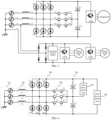
FIG. 1 is a topology diagram of a three-phase passive PFC circuit with an auxiliary power supply and two direct-current fan loads in the existing technology; -
FIG. 2 is a topology diagram of a two-level active PFC circuit with an auxiliary power supply and two direct-current fan loads in the existing technology; -
FIG. 3 is a topology diagram of a T-type three-level active PFC circuit with an auxiliary power supply and two direct-current fan loads in the existing technology; -
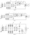
FIG. 4 is a topology diagram of a T-type three-level active PFC circuit with a direct-current load connected in parallel to an upper half bus provided by an embodiment of the present disclosure; -
FIG. 5 is a topology diagram of a T-type three-level active PFC circuit with a direct-current load connected in parallel to an upper half bus provided by another embodiment of the present disclosure; -
FIG. 6 is a topology diagram of a T-type three-level active PFC circuit with a direct-current load connected in parallel to an upper half bus provided by another embodiment of the present disclosure; -
FIG. 7 is a topology diagram of a T-type three-level active PFC circuit with a direct-current load connected in parallel to an upper half bus provided by another embodiment of the present disclosure; -
FIG. 8 is a topology diagram of a T-type three-level active PFC circuit with a direct-current load connected in parallel to an upper half bus provided by another embodiment of the present disclosure; -
FIG. 9 is a topology diagram of a T-type three-level active PFC circuit with a direct-current load connected in parallel to an upper half bus provided by another embodiment of the present disclosure; -
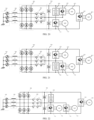
FIG. 10 is a topology diagram of a T-type three-level active PFC circuit with a direct-current load connected in parallel to a lower half bus provided by an embodiment of the present disclosure; -
FIG. 11 is a topology diagram of a T-type three-level active PFC circuit with a direct-current load connected in parallel to a lower half bus provided by another embodiment of the present disclosure; -
FIG. 12 is a topology diagram of a T-type three-level active PFC circuit with a direct-current load connected in parallel to a lower half bus provided by another embodiment of the present disclosure; -
FIG. 13 is a topology diagram of a T-type three-level active PFC circuit with a direct-current load connected in parallel to a lower half bus provided by another embodiment of the present disclosure; -
FIG. 14 is a topology diagram of a T-type three-level active PFC circuit with a direct-current load connected in parallel to a lower half bus provided by another embodiment of the present disclosure; -
FIG. 15 is a topology diagram of a T-type three-level active PFC circuit with a direct-current load connected in parallel to a lower half bus provided by another embodiment of the present disclosure; -
FIG. 16 is a topology diagram of a T-type three-level active PFC circuit with direct-current loads connected in parallel to an upper half bus and a lower half bus respectively provided by an embodiment of the present disclosure; -
FIG. 17 is a topology diagram of a T-type three-level active PFC circuit with direct-current loads connected in parallel to an upper half bus and a lower half bus respectively provided by another embodiment of the present disclosure; -
FIG. 18 is a topology diagram of a T-type three-level active PFC circuit with direct-current loads connected in parallel to an upper half bus and a lower half bus respectively provided by another embodiment of the present disclosure; -
FIG. 19 is a topology diagram of a T-type three-level active PFC circuit with direct-current loads connected in parallel to an upper half bus and a lower half bus respectively provided by another embodiment of the present disclosure; -
FIG. 20 is a topology diagram of a T-type three-level active PFC circuit with direct-current loads connected in parallel to an upper half bus and a lower half bus respectively provided by another embodiment of the present disclosure; -
FIG. 21 is a topology diagram of a T-type three-level active PFC circuit with direct-current loads connected in parallel to an upper half bus and a lower half bus respectively provided by another embodiment of the present disclosure; -
FIG. 22 is a topology diagram of a T-type three-level active PFC circuit with direct-current loads connected in parallel to an upper half bus and a lower half bus respectively provided by another embodiment of the present disclosure; -
FIG. 23 is a topology diagram of a T-type three-level active PFC circuit with direct-current loads connected in parallel to an upper half bus and a lower half bus respectively provided by another embodiment of the present disclosure; -
FIG. 24 is a schematic structural diagram regarding a first bidirectional switch, a second bidirectional switch and a third bidirectional switch provided by an embodiment of the present disclosure; -
FIG. 25 is a schematic structural diagram regarding a first bidirectional switch, a second bidirectional switch and a third bidirectional switch provided by another embodiment of the present disclosure; and -
FIG. 26 is a schematic structural diagram regarding a first bidirectional switch, a second bidirectional switch and a third bidirectional switch provided by another embodiment of the present disclosure. - The embodiments of the present disclosure will be described in detail hereinafter. Examples of the embodiments are shown in the accompanying drawings. The same or similar reference numerals throughout the drawings denote the same or similar elements or elements having the same or similar functions. The embodiments described below with reference to the accompanying drawings are as examples and are only intended to explain the present disclosure, but should not be understood as limiting the present disclosure.
- In the description of the present disclosure, it should be understood that the orientation or position relation related to the orientation description, such as the orientation or position relation indicated by the upper, lower, front, rear, left, right, etc., is based on the orientation or position relation shown in the drawings, which is only utilized for convenience of description of the present disclosure and simplification of description instead of indicating or implying that the indicated device or element must have a specific orientation, and be constructed and operated in a specific orientation, and thus shall not be understood as a limitation to the present disclosure.
- In the description of the present disclosure, the meaning of several is one or multiple, and the meaning of multiple is above two. The meanings of greater than, less than, more than, etc., are understood as not comprising this number, while the meanings of above, below, within, etc., are understood as comprising this number. If there is a description of first and second, it is only for the purpose of distinguishing technical features, and shall not be understood as indicating or implying relative importance, implicitly indicating the number of the indicated technical features or implicitly indicating the order of the indicated technical features.
- In the description of the present disclosure, unless otherwise explicitly defined, words such as setting, installing and connecting should be understood in a broad sense, and those having ordinary skill in the art can reasonably determine the meanings of the above words in the present disclosure in combination with the contents of the technical solutions.
- In the related art, for a high-efficiency variable-frequency air-conditioning system powered by a three-phase power supply, except for a variable-frequency compressor load, a direct-current fan load or an auxiliary power supply may be provided, where some air-conditioning systems are provided with one direct-current fan, and some air-conditioning systems are provided two or more direct-current fans. A solution in the existing technology is generally as follows: the three-phase power supply outputs a voltage of a high-voltage direct-current bus after passing through a passive PFC rectifier circuit or a two-level active PFC rectifier circuit, and the variable-frequency compressor load is connected to the voltage of the high-voltage direct-current bus. However, the direct-current fan load and the auxiliary power supply are powered by an additional independent phase voltage after rectification instead of being powered from the voltage of the high-voltage direct-current bus. The reason for such design is that: the auxiliary power supply and an IPM module driving the direct-current fan have insufficient withstand voltage, and cannot be directly powered from the high-voltage direct-current bus.
- In an example, an effective value of a three-phase line voltage is nominally 380 V, and then the voltage of the high-voltage direct-current bus after rectification is 537 V. With 10% allowable error of power supply voltage fluctuation, the voltage of the high-voltage direct-current bus may probably reach 590 V. Under the control of the active PFC, the voltage of the direct-current bus can be further increased. A withstand voltage of a high-voltage electrolytic capacitor is generally lower than 450 V. Under this application scene, a withstand voltage of a high-voltage electrolytic capacitor of a direct-current bus has to be increased by a two-stage series connection mode, and the withstand voltage of the two-stage series connection can reach 900 V theoretically. However, the withstand voltage of the IPM module driving the direct-current fan is generally 500 V or 600 V, and in addition to a withstand voltage derating requirement on the IPM module, an input voltage of the IPM module driving the direct-current fan is generally lower than 450V in fact. As the voltage of the high-voltage direct-current bus is higher than the input voltage of the IPM module driving the direct-current fan, the IPM module cannot be directly powered from the high-voltage direct-current bus.
- In addition, similarly, a direct-current input voltage of the auxiliary power supply in the air-conditioning system is also required to be lower than 450 V. The reason is that a withstand voltage of a switching power supply chip of an auxiliary power supplies such as a flyback switching power supply is generally lower than 700 V, while an actual peak voltage of the switching power supply chip is a sum of a direct-current input voltage, a reflected voltage of a switch transformer (100 V to 200 V) and a leakage inductance voltage drop (100 V to 200 V), so the direct-current input voltage of the auxiliary power supply is generally lower than 450 V when the auxiliary power supply works stably. In other words, the auxiliary power supply cannot be powered from the high-voltage direct-current bus either, but needs to be powered by an additional independent phase voltage after rectification.
- Based on the above design reasons, present circuit topology diagrams of an air-conditioning system powered by a three-phase power supply mainly comprise, but are not limited to the following three types, which are circuit topology diagrams shown in
FIG. 1 to FIG. 3 respectively. - For a topology diagram of a three-phase passive PFC circuit with an auxiliary power supply and two direct-current fan loads shown in
FIG. 1 , a variable-frequency compressor load is connected to a high-voltage direct-current bus. Moreover, as the voltage of the high-voltage direct-current bus exceeds the direct-current input voltage requirement of an IPM module of the direct-current fan or the auxiliary power supply, the direct-current fan load or the auxiliary power supply is powered by an additional independent phase voltage after rectification instead of being powered from the voltage of the high-voltage direct-current bus. - For a topology diagram of a two-level active PFC circuit with an auxiliary power supply and two direct-current fan loads shown in
FIG. 2 , a variable-frequency compressor load is connected to a voltage of a high-voltage direct-current bus. Moreover, as the voltage of the high-voltage direct-current bus exceeds the direct-current input voltage requirement of an IPM module of the direct-current fan or the auxiliary power supply, the direct-current fan load or the auxiliary power supply is powered by an additional independent phase voltage after rectification instead of being powered from the voltage of the high-voltage direct-current bus. - For a topology diagram of a T-type three-level active PFC circuit with an auxiliary power supply and two direct-current fan loads shown in
FIG. 3 , a variable-frequency compressor load is connected to a voltage of a high-voltage direct-current bus. Moreover, as the voltage of the high-voltage direct-current bus exceeds the direct-current input voltage requirement of an IPM module of the direct-current fan or the auxiliary power supply, the direct-current fan load or the auxiliary power supply is powered by an additional independent phase voltage after rectification instead of being powered from the voltage of the high-voltage direct-current bus. - For the above-mentioned existing power supply solution, there is a need to use a rectified independent phase voltage to supply power to the direct-current fan load and the auxiliary power supply, so that the rectified direct-current voltage can meet the withstand voltage requirements of the IPM module and the auxiliary power supply. However, this power supply solution would cause the load supplied by the phase of the direct-current fan load or the auxiliary power supply to be higher than that of the other two phases, and this additional load does not pass through the two-level active PFC circuit, resulting in a significantly larger harmonic of this phase current and unbalanced three phase currents, and being difficult to meet the harmonic requirements of the IEC.
- Therefore, based on the above situations, the embodiments of the present disclosure provide an electronic circuit and an air conditioner, where the electronic circuit comprises a rectifier module and an energy storage module. The rectifier module comprises a three-phase rectifier bridge and a bidirectional switch assembly, and the three-phase rectifier bridge comprises a first bridge arm, a second bridge arm and a third bridge arm which are connected in parallel to each other. The bidirectional switch assembly comprises a first bidirectional switch, a second bidirectional switch and a third bidirectional switch, one end of the first bidirectional switch is connected to a midpoint of the first bridge arm, one end of the second bidirectional switch is connected to a midpoint of the second bridge arm, and one end of the third bidirectional switch is connected to a midpoint of the third bridge arm. The energy storage module is connected to a direct-current output end of the rectifier module, the energy storage module comprises two capacitors which are connected in series to each other, and the other end of the first bidirectional switch, the other end of the second bidirectional switch and the other end of the third bidirectional switch are all connected between the two capacitors. At least one capacitor is connected in parallel with a direct-current load. According to the technical solution of the embodiments of the present disclosure, direct-current loads with low voltage resistance performance, such as the direct-current fan load or the auxiliary power supply, are connected in parallel to the capacitors in the energy storage module, so that the direct-current loads with low voltage resistance performance, such as the direct-current fan load or the auxiliary power supply, can be supplied with power through the capacitors in the energy storage module. Moreover, three phase currents of the three-phase alternating-current power supply can be balanced, thus avoiding a harmonic of a certain phase current from being significantly large and effectively reducing the harmonic.
- The embodiments of the present disclosure are described below with reference to the accompanying drawings.
- As shown in
FIG. 4 ,FIG. 10 andFIG. 16 ,FIG. 4 ,FIG. 10 andFIG. 16 are schematic diagrams of the electronic circuit provided by some embodiments of the present disclosure. - In an embodiment, the electronic circuit comprises a rectifier module and an
energy storage module 500. The rectifier module comprises a three-phase rectifier bridge 300 and abidirectional switch assembly 400, and the three-phase rectifier bridge 300 comprises a first bridge arm, a second bridge arm and a third bridge arm which are connected in parallel to each other. Thebidirectional switch assembly 400 comprises a first bidirectional switch, a second bidirectional switch and a third bidirectional switch, one end of the first bidirectional switch is connected to a midpoint of the first bridge arm, one end of the second bidirectional switch is connected to a midpoint of the second bridge arm, and one end of the third bidirectional switch is connected to a midpoint of the third bridge arm. Theenergy storage module 500 is connected to a direct-current output end of the rectifier module, theenergy storage module 500 comprises two capacitors which are connected in series to each other, and the other end of the first bidirectional switch, the other end of the second bidirectional switch and the other end of the third bidirectional switch are all connected between the two capacitors. At least one capacitor is connected in parallel with a direct-current load. - In an embodiment, as the direct-current loads with low voltage resistance performance, such as the direct-current fan load or the auxiliary power supply, are connected in parallel to the capacitors in the energy storage module according to the embodiments of the present disclosure, so that the direct-current loads with low voltage resistance performance, such as the direct-current fan load or the auxiliary power supply, can be supplied with power through the capacitors in the
energy storage module 500. Moreover, three phase currents of the three-phase alternating-current power supply can be balanced, thus avoiding a harmonic of a certain phase current from being significantly large and effectively reducing the harmonic. - It should be noted that as for the first bridge arm, the second bridge arm and the third bridge arm in the three-
phase rectifier bridge 300 mentioned above, in some embodiments, the first bridge arm comprises a first diode D1 and a second diode D2 as shown inFIG. 4 ,FIG. 10 andFIG. 16 , the second bridge arm comprises a third diode D3 and a fourth diode D4 as shown inFIG. 4 ,FIG. 10 andFIG. 16 , and the third bridge arm comprises a fifth diode D5 and a sixth diode D6 as shown inFIG. 4 ,FIG. 10 andFIG. 16 . - In an embodiment, the first bidirectional switch, the second bidirectional switch and the third bidirectional switch in the
bidirectional switch assembly 400 above each comprise two power switch transistors reversely connected in parallel to each other, and the two power switch transistors are each reversely connected in parallel to a diode, as shown inFIG. 24 . In an implementation, the first bidirectional switch comprises a first IGBT module T1 and a second IGBT module T2 as shown inFIG. 4 ,FIG. 10 andFIG. 16 , the second bidirectional switch comprises a third IGBT module T3 and a fourth IGBT module T4 as shown inFIG. 4 ,FIG. 10 andFIG. 16 , and the third bidirectional switch comprises a fifth IGBT module T5 and a sixth IGBT module T6 as shown inFIG. 4 ,FIG. 10 andFIG. 16 . - In an embodiment, the first bidirectional switch, the second bidirectional switch and the third bidirectional switch in the
bidirectional switch assembly 400 above also comprise two power switch transistors reversely connected in series to each other as shown inFIG. 25 in addition to the two power switch transistors reversely connected in parallel to each other as shown inFIG. 24 . In another embodiment, a fourth bridge arm, a power switch transistor and a fifth bridge arm which are connected in parallel to each other as shown inFIG. 26 can be comprised. In an implementation, the fourth bridge arm comprise a seventh diode D7 and an eighth diode D8 as shown inFIG. 26 , and the fifth bridge arm comprise a ninth diode D9 and a tenth diode D10 as shown inFIG. 26 . In an example, at least one diode in the seventh diode D7, the eighth diode D8, the ninth diode D9 and the tenth diode D10 can be replaced by a MOS tube, an IGBT tube with anti-parallel diode and other devices with reverse cut-off function. In an example, the above-mentioned power switch transistor can be IGBT, MOSFET and other devices that can be controlled on and off. - In an embodiment, for the direct-current output end and the two capacitors mentioned above, the direct-current output end comprises a positive bus end and a negative bus end, the two capacitors can be the first capacitor C1 and the second capacitor C2 as shown in
FIG. 4 ,FIG. 10 andFIG. 16 respectively, and the positive bus end is connected to the negative bus end through the first capacitor C1 and the second capacitor C2 in succession. - It is worth noting that a half bus in the embodiments of the present disclosure means that in a high-voltage direct-current bus filter circuit adopting two-stage capacitors connected in series, an upper half bus is arranged between a midpoint of the two-stage capacitors connected in series and a positive bus, a lower half bus is arranged between the midpoint of the two-stage capacitors connected in series and the negative bus, and both the upper half bus and the lower half bus are half buses. In an embodiment of the present disclosure, the upper half bus is arranged between a midpoint of the first capacitor C1 and the second capacitor C2 connected in series and the positive bus end, and the lower half bus is arranged between the midpoint of the first capacitor C1 and the second capacitor C2 connected in series and the negative bus end.
- It should be noted that the electronic circuit in an embodiment of the present disclosure comprises, but is not limited to, an alternating-
current input end 100 and aninductance device 200, where the alternating-current input end 100 is connected to the rectifier module through theinductance device 200. - In an embodiment, the alternating-
current input end 100 comprises a first phase input end, a second phase input end and a third phase input end, and theinductance device 200 comprises a first inductor, a second inductor and a third inductor. The first phase input end is connected to the midpoint of the first bridge arm through the first inductor, the second phase input end is connected to the midpoint of the second bridge arm through the second inductor, and the third phase input end is connected to the midpoint of the third bridge arm through the third inductor. In an implementation, the first inductor refers to the first inductor L1 as shown inFIG. 4 ,FIG. 10 andFIG. 16 , the second inductor refers to the second inductor L2 as shown inFIG. 4 ,FIG. 10 andFIG. 16 , and the third inductor refers to the third inductor L3 as shown inFIG. 4 ,FIG. 10 andFIG. 16 . - Based on a topology diagram of a T-type three-level active PFC circuit with a direct-current load connected in parallel to an upper half bus as shown in
FIG. 4 , the first capacitor C1 is connected in parallel with a first direct-current load 600. The first direct-current load 600 comprises, but is not limited to at least one of a first auxiliary power supply module or a first fan module, and the first fan module comprises, but is not limited to a first direct-current fan and a first driver assembly driving the first direct-current fan, and the first driver assembly is connected in parallel to the first capacitor C1. - In some embodiments, in the actual application process, the topology diagram of the T-type three-level active PFC circuit shown in
FIG. 4 comprise, but is not limited to topology diagrams of T-type three-level active PFC circuits with a direct-current load connected in parallel to an upper half bus as shown inFIG. 5 to FIG. 9 . - As shown in
FIG. 5 , the first capacitor C1 is connected in parallel with a first direct-current load 600, where the first direct-current load 600 is a first fan module. The first fan module comprises a first direct-current fan 612 and afirst driver assembly 611 driving the first direct-current fan 612, and thefirst driver assembly 611 is connected in parallel to the first capacitor C1. - As shown in
FIG. 6 , the first capacitor C1 is connected in parallel with a first direct-current load 600, where the first direct-current load 600 is a first auxiliarypower supply module 620. - As shown in
FIG. 7 , the first capacitor C1 is connected in parallel with a first direct-current load 600, where the first direct-current load 600 comprises two first fan modules. Each first fan module comprises a first direct-current fan 612 and afirst driver assembly 611 driving the first direct-current fan 612, and thefirst driver assembly 611 is connected in parallel to the first capacitor C1. - As shown in
FIG. 8 , the first capacitor C1 is connected in parallel with a first direct-current load 600, where the first direct-current load 600 comprises a first auxiliarypower supply module 620 and one first fan module. The first fan module comprises a first direct-current fan 612 and afirst driver assembly 611 driving the first direct-current fan 612, and thefirst driver assembly 611 is connected in parallel to the first capacitor C1. - As shown in
FIG. 9 , the first capacitor C1 is connected in parallel with a first direct-current load 600, where the first direct-current load 600 comprises a first auxiliarypower supply module 620 and two first fan modules. Each first fan module comprises a first direct-current fan 612 and afirst driver assembly 611 driving the first direct-current fan 612, and thefirst driver assembly 611 is connected in parallel to the first capacitor C1. - Based on a topology diagram of a T-type three-level active PFC circuit with a direct-current load connected in parallel to a lower half bus as shown in
FIG. 10 , the second capacitor C2 is connected in parallel with a second direct-current load 700. The second direct-current load 700 comprises, but is not limited to at least one of a second auxiliary power supply module or a second fan module, and the second fan module comprises a second direct-current fan and a second driver assembly driving the second direct-current fan, and the second driver assembly is connected in parallel to the second capacitor C2. - In some embodiments, in the actual application process, the topology diagram of the T-type three-level active PFC circuit shown in
FIG. 10 comprise, but is not limited to topology diagrams of T-type three-level active PFC circuits with a direct-current load connected in parallel to a lower half bus as shown inFIG. 11 to FIG. 15 . - As shown in
FIG. 11 , the second capacitor C2 is connected in parallel with a second direct-current load 700, where the second direct-current load 700 is a second fan module, and the second fan module comprises a second direct-current fan 712 and asecond driver assembly 711 driving the second direct-current fan 712, and thesecond driver assembly 711 is connected in parallel to the second capacitor C2. - As shown in
FIG. 12 , the second capacitor C2 is connected in parallel with a second direct-current load 700, where the second direct-current load 700 is a second auxiliarypower supply module 720. - As shown in
FIG. 13 , the second capacitor C2 is connected in parallel with a second direct-current load 700, where the second direct-current load 700 comprises two second fan modules, each second fan module comprises a second direct-current fan 712 and asecond driver assembly 711 driving the second direct-current fan 712, and thesecond driver assembly 711 is connected in parallel to the second capacitor C2. - As shown in
FIG. 14 , the second capacitor C2 is connected in parallel with a second direct-current load 700, where the second direct-current load 700 comprises a second auxiliarypower supply module 720 and one second fan module The second fan module comprises a second direct-current fan 712 and asecond driver assembly 711 driving the second direct-current fan 712, and thesecond driver assembly 711 is connected in parallel to the second capacitor C2. - As shown in
FIG. 15 , the second capacitor C2 is connected in parallel with a second direct-current load 700, where the second direct-current load 700 comprises a second auxiliarypower supply module 720 and two second fan modules. Each second fan module comprises a second direct-current fan 712 and asecond driver assembly 711 driving the second direct-current fan 712, and thesecond driver assembly 711 is connected in parallel to the second capacitor C2. - Based on a topology diagram of a T-type three-level active PFC circuit with direct-current loads connected in parallel to an upper half bus and a lower half bus respectively as shown in
FIG. 16 , the first capacitor C1 is connected in parallel with a first direct-current load 600, and the second capacitor C2 is connected in parallel with a second direct-current load 700. The first direct-current load 600 comprises a first auxiliary power supply module and/or a first fan module. The first fan module comprises a first direct-current fan and a first driver assembly driving the first direct-current fan, and the first driver assembly is connected in parallel to the first capacitor C1. The second direct-current load 700 comprises a second auxiliary power supply module and/or a second fan module. The second fan module comprises a second direct-current fan and a second driver assembly driving the second direct-current fan, and the second driver assembly is connected in parallel to the second capacitor C2. - In some embodiments, in the actual application process, the topology diagram of the T-type three-level active PFC circuit shown in
FIG. 16 comprise, but is not limited to topology diagrams of T-type three-level active PFC circuits with direct-current loads connected in parallel on an upper half bus and a lower half bus respectively as shown inFIG. 17 to FIG. 23 . - As shown in
FIG. 17 , the first capacitor C1 is connected in parallel with a first direct-current load 600, and the second capacitor C2 is connected in parallel with a second direct-current load 700. The first direct-current load 600 is a first fan module, the first fan module comprises a first direct-current fan 612 and afirst driver assembly 611 driving the first direct-current fan 612, and thefirst driver assembly 611 is connected in parallel to the first capacitor C1. The second direct-current load 700 is a second fan module, the second fan module comprises a second direct-current fan 712 and asecond driver assembly 711 driving the second direct-current fan 712, and thesecond driver assembly 711 is connected in parallel to the second capacitor C2. - As shown in
FIG. 18 , the first capacitor C1 is connected in parallel with a first direct-current load 600, and the second capacitor C2 is connected in parallel with a second direct-current load 700. The first direct-current load 600 is a first fan module, the first fan module comprises a first direct-current fan 612 and afirst driver assembly 611 driving the first direct-current fan 612, and thefirst driver assembly 611 is connected in parallel to the first capacitor C1. The second direct-current load 700 is a second auxiliarypower supply module 720. - As shown in
FIG. 19 , the first capacitor C1 is connected in parallel with a first direct-current load 600, and the second capacitor C2 is connected in parallel with a second direct-current load 700. The first direct-current load 600 is a first auxiliarypower supply module 620. The second direct-current load 700 is a second fan module, the second fan module comprises a second direct-current fan 712 and asecond driver assembly 711 driving the second direct-current fan 712, and thesecond driver assembly 711 is connected in parallel to the second capacitor C2. - As shown in
FIG. 20 , the first capacitor C1 is connected in parallel with a first direct-current load 600, and the second capacitor C2 is connected in parallel with a second direct-current load 700. The first direct-current load 600 comprises a first auxiliarypower supply module 620 and one first fan module, the first fan module comprises a first direct-current fan 612 and afirst driver assembly 611 driving the first direct-current fan 612, and thefirst driver assembly 611 is connected in parallel to the first capacitor C1. The second direct-current load 700 is a second fan module, the second fan module comprises a second direct-current fan 712 and asecond driver assembly 711 driving the second direct-current fan 712, and thesecond driver assembly 711 is connected in parallel to the second capacitor C2. - As shown in
FIG. 21 , the first capacitor C1 is connected in parallel with a first direct-current load 600, and the second capacitor C2 is connected in parallel with a second direct-current load 700. The first direct-current load 600 is a first fan module, the first fan module comprises a first direct-current fan 612 and afirst driver assembly 611 driving the first direct-current fan 612, and thefirst driver assembly 611 is connected in parallel to the first capacitor C1. The second direct-current load 700 comprises a second auxiliarypower supply module 720 and one second fan module, the second fan module comprises a second direct-current fan 712 and asecond driver assembly 711 driving the second direct-current fan 712, and thesecond driver assembly 711 is connected in parallel to the second capacitor C2. - As shown in
FIG. 22 , the first capacitor C1 is connected in parallel with a first direct-current load 600, and the second capacitor C2 is connected in parallel with a second direct-current load 700. The first direct-current load 600 is a first auxiliarypower supply module 620. The second direct-current load 700 comprises two second fan modules, each second fan module comprises a second direct-current fan 712 and asecond driver assembly 711 driving the second direct-current fan 712, and thesecond driver assembly 711 is connected in parallel to the second capacitor C2. - As shown in
FIG. 23 , the first capacitor C1 is connected in parallel with a first direct-current load 600, and the second capacitor C2 is connected in parallel with a second direct-current load 700. The first direct-current load 600 comprises two first fan modules, each first fan module comprises a first direct-current fan 612 and afirst driver assembly 611 driving the first direct-current fan 612, and thefirst driver assembly 611 is connected in parallel to the first capacitor C1. The second direct-current load 700 is a second auxiliarypower supply module 720. - In an embodiment, numbers of the first fan module and the second fan module in the above embodiments are at least one.
- In some embodiments, referring to
FIG. 4 to FIG. 23 , the electronic circuit of the embodiments of the present disclosure comprise, but is not limited to a third direct-current load 800, where the third direct-current load 800 is connected to the direct-current output end. - In an embodiment, the third direct-
current load 800 comprises acompressor 812 and athird driver assembly 811 driving thecompressor 812, and thethird driver assembly 811 is connected to the direct-current output end. - In some embodiment, the
first driver assembly 611, thesecond driver assembly 711 and thethird driver assembly 811 can be IPM modules driving the direct-current fan. - On the basis of the above-mentioned electronic circuit, various embodiments of the air conditioner according to the embodiments of the present disclosure are proposed below.
- An embodiment of the present disclosure also provides an air conditioner, which comprises the electronic circuit in any of the above embodiments.
- Since the air conditioner according to the embodiments of the present disclosure comprises the electronic circuit according to any of the embodiments above, the implementation and technical effects of the air conditioner according to the embodiments of the present disclosure refer to the implementation and technical effects of the electronic circuit of any of the above embodiments.
- The foregoing describes some embodiments of the present disclosure in detail, but the present disclosure is not limited to the foregoing embodiments. Those having ordinary skill in the art can make various equal deformations or replacements without departing from the spirit of the present disclosure, and these equal deformations or replacements shall all fall within the scope limited by the claims of the present disclosure.
Claims (13)
- An electronic circuit, comprising:a rectifier module comprising a three-phase rectifier bridge and a bidirectional switch assembly, wherein the three-phase rectifier bridge comprises a first bridge arm, a second bridge arm and a third bridge arm connected in parallel to each other; and the bidirectional switch assembly comprises a first bidirectional switch, a second bidirectional switch and a third bidirectional switch, an end of the first bidirectional switch is connected to a midpoint of the first bridge arm, an end of the second bidirectional switch is connected to a midpoint of the second bridge arm, and an end of the third bidirectional switch is connected to a midpoint of the third bridge arm; andan energy storage module connected to a direct-current output end of the rectifier module, wherein the energy storage module comprises two capacitors connected in series to each other, and an other end of the first bidirectional switch, an other end of the second bidirectional switch and an other end of the third bidirectional switch are all connected between the two capacitors;wherein, at least one capacitor is connected in parallel with a direct-current load.
- The electronic circuit according to claim 1, wherein the direct-current output end comprises a positive bus end and a negative bus end, the two capacitors are a first capacitor and a second capacitor respectively, and the positive bus end is connected to the negative bus end through the first capacitor and the second capacitor in succession.
- The electronic circuit according to claim 2, wherein the first capacitor is connected in parallel with a first direct-current load, the first direct-current load comprises a first auxiliary power supply module and/or a first fan module, the first fan module comprises a first direct-current fan and a first driver assembly driving the first direct-current fan, and the first driver assembly is connected in parallel to the first capacitor.
- The electronic circuit according to claim 2, wherein the second capacitor is connected in parallel with a second direct-current load, the second direct-current load comprises a second auxiliary power supply module and/or a second fan module, the second fan module comprises a second direct-current fan and a second driver assembly driving the second direct-current fan, and the second driver assembly is connected in parallel to the second capacitor.
- The electronic circuit according to claim 2, wherein the first capacitor is connected in parallel with a first direct-current load, and the second capacitor is connected in parallel with a second direct-current load; the first direct-current load comprises a first auxiliary power supply module and/or a first fan module, the first fan module comprises a first direct-current fan and a first driver assembly capacitor; and the second direct-current load comprises a second auxiliary power supply module and/or a second fan module, the second fan module comprises a second direct-current fan and a second driver assembly driving the second direct-current fan, and the second driver assembly is connected in parallel to the second capacitor.
- The electronic circuit according to claim 1, further comprising a third direct-current load, wherein the third direct-current load is connected to the direct-current output end.
- The electronic circuit according to claim 6, wherein the third direct-current load comprises a compressor and a third driver assembly driving the compressor, and the third driver assembly is connected to the direct-current output end.
- The electronic circuit according to claim 1, further comprising an alternating-current input end and an inductance device, wherein the alternating-current input end is connected to the rectifier module through the inductance device.
- The electronic circuit according to claim 8, wherein the alternating-current input end comprises a first phase input end, a second phase input end and a third phase input end, the inductance device comprises a first inductor, a second inductor and a third inductor, the first phase input end is connected to the midpoint of the first bridge arm through the first inductor, the second phase input end is connected to the midpoint of the second bridge arm through the second inductor, and the third phase input end is connected to the midpoint of the third bridge arm through the third inductor.
- The electronic circuit according to any one of claims 1 to 9, wherein the first bidirectional switch, the second bidirectional switch and the third bidirectional switch all comprise two power switch transistors reversely connected in series to each other.
- The electronic circuit according to any one of claims 1 to 9, wherein the first bidirectional switch, the second bidirectional switch and the third bidirectional switch all comprise two power switch transistors reversely connected in parallel to each other, and the two power switch transistors are each reversely connected in parallel to a diode.
- The electronic circuit according to any one of claims 1 to 9, wherein the first bidirectional switch, the second bidirectional switch and the third bidirectional switch all comprise a fourth bridge arm, a power switch transistor and a fifth bridge arm connected in parallel to each other.
- An air conditioner, comprising an electronic circuit according to any one of claims 1 to 12.
Applications Claiming Priority (3)
| Application Number | Priority Date | Filing Date | Title |
|---|---|---|---|
| CN202011063267.7A CN114337328A (en) | 2020-09-30 | 2020-09-30 | Electronic circuit and air conditioner |
| CN202022223541.4U CN212305171U (en) | 2020-09-30 | 2020-09-30 | Electronic circuit and air conditioner |
| PCT/CN2021/118018 WO2022068566A1 (en) | 2020-09-30 | 2021-09-13 | Electronic circuit and air conditioner |
Publications (2)
| Publication Number | Publication Date |
|---|---|
| EP4178098A1 true EP4178098A1 (en) | 2023-05-10 |
| EP4178098A4 EP4178098A4 (en) | 2023-12-13 |
Family
ID=80949657
Family Applications (1)
| Application Number | Title | Priority Date | Filing Date |
|---|---|---|---|
| EP21874227.8A Withdrawn EP4178098A4 (en) | 2020-09-30 | 2021-09-13 | Electronic circuit and air conditioner |
Country Status (3)
| Country | Link |
|---|---|
| US (1) | US20230275525A1 (en) |
| EP (1) | EP4178098A4 (en) |
| WO (1) | WO2022068566A1 (en) |
Cited By (1)
| Publication number | Priority date | Publication date | Assignee | Title |
|---|---|---|---|---|
| EP4496205A4 (en) * | 2022-06-29 | 2025-07-23 | Foshan Shunde Midea Electric Science And Tech Co Ltd | Three-phase power supply conversion circuit for household appliance, household appliance and power-on control method |
Family Cites Families (11)
| Publication number | Priority date | Publication date | Assignee | Title |
|---|---|---|---|---|
| US20140043870A1 (en) * | 2012-08-07 | 2014-02-13 | Yaskawa America, Inc. | Three phase boost converter to achieve unity power factor and low input current harmonics for use with ac to dc rectifiers |
| US9099935B2 (en) * | 2013-01-14 | 2015-08-04 | Yaskawa America, Inc. | Single-phase active front end rectifier system for use with three-phase variable frequency drives |
| CN104836463B (en) * | 2015-04-30 | 2018-01-05 | 华南理工大学 | Mixing transformation system based on three-phase PWM rectification Yu multiple-unit uncontrollable rectifier |
| CN106533218B (en) * | 2017-01-05 | 2019-02-01 | 北京新能源汽车股份有限公司 | Three-phase rectification circuit and drive control method |
| JP7034782B2 (en) * | 2018-03-16 | 2022-03-14 | 三菱重工サーマルシステムズ株式会社 | Step-out detector, duct type air conditioner equipped with it, step-out detection method, and step-out detection program |
| CN209105059U (en) * | 2018-11-02 | 2019-07-12 | 南京熊猫电子股份有限公司 | A kind of alternating current-direct current two-way changing circuit |
| CN109245594B (en) * | 2018-11-02 | 2024-06-14 | 南京熊猫电子股份有限公司 | AC/DC bidirectional conversion circuit and control method thereof |
| IT201800020518A1 (en) * | 2018-12-20 | 2020-06-20 | Carel Ind Spa | CONTROL DEVICE FOR A THREE-PHASE POWERED REFRIGERATING MACHINE AND THREE-PHASE POWERED REFRIGERATING MACHINE THAT INCLUDES IT |
| CN112448594B (en) * | 2019-08-28 | 2022-05-31 | 台达电子工业股份有限公司 | Indirect matrix converter and rectification module |
| US11021069B1 (en) * | 2020-01-30 | 2021-06-01 | Ford Global Technologies, Llc | Multisource magnetic integration using a current source fed transformer structure with decoupled secondary windings |
| CN212305171U (en) * | 2020-09-30 | 2021-01-05 | 重庆美的制冷设备有限公司 | Electronic circuit and air conditioner |
-
2021
- 2021-09-13 EP EP21874227.8A patent/EP4178098A4/en not_active Withdrawn
- 2021-09-13 WO PCT/CN2021/118018 patent/WO2022068566A1/en not_active Ceased
- 2021-09-13 US US18/016,277 patent/US20230275525A1/en active Pending
Cited By (1)
| Publication number | Priority date | Publication date | Assignee | Title |
|---|---|---|---|---|
| EP4496205A4 (en) * | 2022-06-29 | 2025-07-23 | Foshan Shunde Midea Electric Science And Tech Co Ltd | Three-phase power supply conversion circuit for household appliance, household appliance and power-on control method |
Also Published As
| Publication number | Publication date |
|---|---|
| US20230275525A1 (en) | 2023-08-31 |
| WO2022068566A1 (en) | 2022-04-07 |
| EP4178098A4 (en) | 2023-12-13 |
Similar Documents
| Publication | Publication Date | Title |
|---|---|---|
| CN212305171U (en) | Electronic circuit and air conditioner | |
| US7830036B2 (en) | Power electronic module pre-charge system and method | |
| CN114337332B (en) | Three-phase power supply conversion circuit, circuit control method, circuit board and air conditioner | |
| CN101621255B (en) | A cascaded energy-fed high-voltage converter | |
| CN114337328A (en) | Electronic circuit and air conditioner | |
| JP3981886B2 (en) | Rectifier circuit | |
| EP4178098A1 (en) | Electronic circuit and air conditioner | |
| CN108322027A (en) | A kind of power conversion circuit | |
| CN217135394U (en) | Control circuit and air conditioner | |
| CN222052882U (en) | Three-phase active PFC circuit, circuit board, controller and air conditioner | |
| CN222052881U (en) | Three-phase active PFC circuit, circuit board, controller and air conditioner | |
| CN108667311A (en) | Frequency conversion controller and air conditioner for three-phase power supply | |
| CN219760858U (en) | Power supply monitoring and power-off control multiplexing circuit and driving system | |
| CN111431413A (en) | LL C resonant circuit | |
| CN215498777U (en) | Full direct current driving system of fan wall unit | |
| CN209748427U (en) | Refrigerator frequency conversion driver | |
| CN212413080U (en) | Motor drive circuit, motor control circuit and air conditioner | |
| CN212413081U (en) | Motor drive circuit, motor control circuit and air conditioner | |
| CN209233733U (en) | The frequency-variable controller and air conditioner of three phase mains | |
| CN223379092U (en) | Circuit structure and air conditioning system | |
| CN223680979U (en) | Drive protection circuit and electric equipment | |
| US20260031744A1 (en) | Power Converter With Auxiliary Voltage Supply | |
| CN223744593U (en) | DC conversion circuit and vehicle-mounted charger | |
| CN221067997U (en) | Air conditioner power management circuit, system and parking air conditioner | |
| US12463550B2 (en) | Lumped power supply circuit for converting an AC signal into a DC signal |
Legal Events
| Date | Code | Title | Description |
|---|---|---|---|
| STAA | Information on the status of an ep patent application or granted ep patent |
Free format text: STATUS: THE INTERNATIONAL PUBLICATION HAS BEEN MADE |
|
| PUAI | Public reference made under article 153(3) epc to a published international application that has entered the european phase |
Free format text: ORIGINAL CODE: 0009012 |
|
| STAA | Information on the status of an ep patent application or granted ep patent |
Free format text: STATUS: REQUEST FOR EXAMINATION WAS MADE |
|
| 17P | Request for examination filed |
Effective date: 20230203 |
|
| AK | Designated contracting states |
Kind code of ref document: A1 Designated state(s): AL AT BE BG CH CY CZ DE DK EE ES FI FR GB GR HR HU IE IS IT LI LT LU LV MC MK MT NL NO PL PT RO RS SE SI SK SM TR |
|
| A4 | Supplementary search report drawn up and despatched |
Effective date: 20231115 |
|
| RIC1 | Information provided on ipc code assigned before grant |
Ipc: H02M 1/42 20070101ALI20231109BHEP Ipc: H02M 5/458 20060101ALI20231109BHEP Ipc: H02M 1/00 20060101ALI20231109BHEP Ipc: F24F 11/88 20180101ALI20231109BHEP Ipc: H02M 1/12 20060101ALI20231109BHEP Ipc: H02M 7/219 20060101AFI20231109BHEP |
|
| DAV | Request for validation of the european patent (deleted) | ||
| DAX | Request for extension of the european patent (deleted) | ||
| STAA | Information on the status of an ep patent application or granted ep patent |
Free format text: STATUS: THE APPLICATION IS DEEMED TO BE WITHDRAWN |
|
| 18D | Application deemed to be withdrawn |
Effective date: 20240606 |