EP4178072A1 - Power integration system with motor drive and battery charging and discharging function - Google Patents
Power integration system with motor drive and battery charging and discharging function Download PDFInfo
- Publication number
- EP4178072A1 EP4178072A1 EP22205737.4A EP22205737A EP4178072A1 EP 4178072 A1 EP4178072 A1 EP 4178072A1 EP 22205737 A EP22205737 A EP 22205737A EP 4178072 A1 EP4178072 A1 EP 4178072A1
- Authority
- EP
- European Patent Office
- Prior art keywords
- power
- battery
- switch
- coupled
- charger
- Prior art date
- Legal status (The legal status is an assumption and is not a legal conclusion. Google has not performed a legal analysis and makes no representation as to the accuracy of the status listed.)
- Pending
Links
Images




Classifications
-
- H—ELECTRICITY
- H02—GENERATION; CONVERSION OR DISTRIBUTION OF ELECTRIC POWER
- H02J—ELECTRIC POWER NETWORKS; CIRCUIT ARRANGEMENTS OR SYSTEMS FOR SUPPLYING OR DISTRIBUTING ELECTRIC POWER; SYSTEMS FOR STORING ELECTRIC ENERGY
- H02J7/00—Circuit arrangements for charging or discharging batteries or for supplying loads from batteries
- H02J7/865—Battery or charger load switching, e.g. concurrent charging and load supply
-
- H—ELECTRICITY
- H02—GENERATION; CONVERSION OR DISTRIBUTION OF ELECTRIC POWER
- H02J—ELECTRIC POWER NETWORKS; CIRCUIT ARRANGEMENTS OR SYSTEMS FOR SUPPLYING OR DISTRIBUTING ELECTRIC POWER; SYSTEMS FOR STORING ELECTRIC ENERGY
- H02J7/00—Circuit arrangements for charging or discharging batteries or for supplying loads from batteries
- H02J7/14—Circuit arrangements for charging or discharging batteries or for supplying loads from batteries for charging batteries from dynamo-electric generators driven at varying speed, e.g. on vehicle
- H02J7/1438—Circuit arrangements for charging or discharging batteries or for supplying loads from batteries for charging batteries from dynamo-electric generators driven at varying speed, e.g. on vehicle in combination with power supplies for loads other than batteries
-
- B—PERFORMING OPERATIONS; TRANSPORTING
- B60—VEHICLES IN GENERAL
- B60L—PROPULSION OF ELECTRICALLY-PROPELLED VEHICLES; SUPPLYING ELECTRIC POWER FOR AUXILIARY EQUIPMENT OF ELECTRICALLY-PROPELLED VEHICLES; ELECTRODYNAMIC BRAKE SYSTEMS FOR VEHICLES IN GENERAL; MAGNETIC SUSPENSION OR LEVITATION FOR VEHICLES; MONITORING OPERATING VARIABLES OF ELECTRICALLY-PROPELLED VEHICLES; ELECTRIC SAFETY DEVICES FOR ELECTRICALLY-PROPELLED VEHICLES
- B60L1/00—Supplying electric power to auxiliary equipment of vehicles
- B60L1/006—Supplying electric power to auxiliary equipment of vehicles to power outlets
-
- B—PERFORMING OPERATIONS; TRANSPORTING
- B60—VEHICLES IN GENERAL
- B60L—PROPULSION OF ELECTRICALLY-PROPELLED VEHICLES; SUPPLYING ELECTRIC POWER FOR AUXILIARY EQUIPMENT OF ELECTRICALLY-PROPELLED VEHICLES; ELECTRODYNAMIC BRAKE SYSTEMS FOR VEHICLES IN GENERAL; MAGNETIC SUSPENSION OR LEVITATION FOR VEHICLES; MONITORING OPERATING VARIABLES OF ELECTRICALLY-PROPELLED VEHICLES; ELECTRIC SAFETY DEVICES FOR ELECTRICALLY-PROPELLED VEHICLES
- B60L15/00—Methods, circuits, or devices for controlling the traction-motor speed of electrically-propelled vehicles
- B60L15/007—Physical arrangements or structures of drive train converters specially adapted for the propulsion motors of electric vehicles
-
- B—PERFORMING OPERATIONS; TRANSPORTING
- B60—VEHICLES IN GENERAL
- B60L—PROPULSION OF ELECTRICALLY-PROPELLED VEHICLES; SUPPLYING ELECTRIC POWER FOR AUXILIARY EQUIPMENT OF ELECTRICALLY-PROPELLED VEHICLES; ELECTRODYNAMIC BRAKE SYSTEMS FOR VEHICLES IN GENERAL; MAGNETIC SUSPENSION OR LEVITATION FOR VEHICLES; MONITORING OPERATING VARIABLES OF ELECTRICALLY-PROPELLED VEHICLES; ELECTRIC SAFETY DEVICES FOR ELECTRICALLY-PROPELLED VEHICLES
- B60L50/00—Electric propulsion with power supplied within the vehicle
- B60L50/20—Electric propulsion with power supplied within the vehicle using propulsion power generated by humans or animals
-
- B—PERFORMING OPERATIONS; TRANSPORTING
- B60—VEHICLES IN GENERAL
- B60L—PROPULSION OF ELECTRICALLY-PROPELLED VEHICLES; SUPPLYING ELECTRIC POWER FOR AUXILIARY EQUIPMENT OF ELECTRICALLY-PROPELLED VEHICLES; ELECTRODYNAMIC BRAKE SYSTEMS FOR VEHICLES IN GENERAL; MAGNETIC SUSPENSION OR LEVITATION FOR VEHICLES; MONITORING OPERATING VARIABLES OF ELECTRICALLY-PROPELLED VEHICLES; ELECTRIC SAFETY DEVICES FOR ELECTRICALLY-PROPELLED VEHICLES
- B60L53/00—Methods of charging batteries, specially adapted for electric vehicles; Charging stations or on-board charging equipment therefor; Exchange of energy storage elements in electric vehicles
- B60L53/20—Methods of charging batteries, specially adapted for electric vehicles; Charging stations or on-board charging equipment therefor; Exchange of energy storage elements in electric vehicles characterised by converters located in the vehicle
- B60L53/24—Using the vehicle's propulsion converter for charging
-
- H—ELECTRICITY
- H02—GENERATION; CONVERSION OR DISTRIBUTION OF ELECTRIC POWER
- H02J—ELECTRIC POWER NETWORKS; CIRCUIT ARRANGEMENTS OR SYSTEMS FOR SUPPLYING OR DISTRIBUTING ELECTRIC POWER; SYSTEMS FOR STORING ELECTRIC ENERGY
- H02J1/00—Circuit arrangements for DC mains or DC distribution networks
- H02J1/10—Parallel operation of DC sources
-
- H—ELECTRICITY
- H02—GENERATION; CONVERSION OR DISTRIBUTION OF ELECTRIC POWER
- H02J—ELECTRIC POWER NETWORKS; CIRCUIT ARRANGEMENTS OR SYSTEMS FOR SUPPLYING OR DISTRIBUTING ELECTRIC POWER; SYSTEMS FOR STORING ELECTRIC ENERGY
- H02J7/00—Circuit arrangements for charging or discharging batteries or for supplying loads from batteries
- H02J7/34—Parallel operation in networks using both storage and other DC sources, e.g. providing buffering
-
- H—ELECTRICITY
- H02—GENERATION; CONVERSION OR DISTRIBUTION OF ELECTRIC POWER
- H02J—ELECTRIC POWER NETWORKS; CIRCUIT ARRANGEMENTS OR SYSTEMS FOR SUPPLYING OR DISTRIBUTING ELECTRIC POWER; SYSTEMS FOR STORING ELECTRIC ENERGY
- H02J7/00—Circuit arrangements for charging or discharging batteries or for supplying loads from batteries
- H02J7/855—Circuit arrangements for charging or discharging batteries or for supplying loads from batteries with circuits adapted for supplying loads from the battery
-
- H—ELECTRICITY
- H02—GENERATION; CONVERSION OR DISTRIBUTION OF ELECTRIC POWER
- H02J—ELECTRIC POWER NETWORKS; CIRCUIT ARRANGEMENTS OR SYSTEMS FOR SUPPLYING OR DISTRIBUTING ELECTRIC POWER; SYSTEMS FOR STORING ELECTRIC ENERGY
- H02J7/00—Circuit arrangements for charging or discharging batteries or for supplying loads from batteries
- H02J7/90—Regulation of charging or discharging current or voltage
- H02J7/96—Regulation of charging or discharging current or voltage in response to battery voltage
-
- H—ELECTRICITY
- H02—GENERATION; CONVERSION OR DISTRIBUTION OF ELECTRIC POWER
- H02M—APPARATUS FOR CONVERSION BETWEEN AC AND AC, BETWEEN AC AND DC, OR BETWEEN DC AND DC, AND FOR USE WITH MAINS OR SIMILAR POWER SUPPLY SYSTEMS; CONVERSION OF DC OR AC INPUT POWER INTO SURGE OUTPUT POWER; CONTROL OR REGULATION THEREOF
- H02M1/00—Details of apparatus for conversion
- H02M1/0067—Converter structures employing plural converter units, other than for parallel operation of the units on a single load
- H02M1/007—Plural converter units in cascade
-
- H—ELECTRICITY
- H02—GENERATION; CONVERSION OR DISTRIBUTION OF ELECTRIC POWER
- H02M—APPARATUS FOR CONVERSION BETWEEN AC AND AC, BETWEEN AC AND DC, OR BETWEEN DC AND DC, AND FOR USE WITH MAINS OR SIMILAR POWER SUPPLY SYSTEMS; CONVERSION OF DC OR AC INPUT POWER INTO SURGE OUTPUT POWER; CONTROL OR REGULATION THEREOF
- H02M3/00—Conversion of DC power input into DC power output
- H02M3/02—Conversion of DC power input into DC power output without intermediate conversion into AC
- H02M3/04—Conversion of DC power input into DC power output without intermediate conversion into AC by static converters
- H02M3/10—Conversion of DC power input into DC power output without intermediate conversion into AC by static converters using discharge tubes with control electrode or semiconductor devices with control electrode
- H02M3/145—Conversion of DC power input into DC power output without intermediate conversion into AC by static converters using discharge tubes with control electrode or semiconductor devices with control electrode using devices of a triode or transistor type requiring continuous application of a control signal
- H02M3/155—Conversion of DC power input into DC power output without intermediate conversion into AC by static converters using discharge tubes with control electrode or semiconductor devices with control electrode using devices of a triode or transistor type requiring continuous application of a control signal using semiconductor devices only
- H02M3/156—Conversion of DC power input into DC power output without intermediate conversion into AC by static converters using discharge tubes with control electrode or semiconductor devices with control electrode using devices of a triode or transistor type requiring continuous application of a control signal using semiconductor devices only with automatic control of output voltage or current, e.g. switching regulators
- H02M3/158—Conversion of DC power input into DC power output without intermediate conversion into AC by static converters using discharge tubes with control electrode or semiconductor devices with control electrode using devices of a triode or transistor type requiring continuous application of a control signal using semiconductor devices only with automatic control of output voltage or current, e.g. switching regulators including plural semiconductor devices as final control devices for a single load
-
- H—ELECTRICITY
- H02—GENERATION; CONVERSION OR DISTRIBUTION OF ELECTRIC POWER
- H02M—APPARATUS FOR CONVERSION BETWEEN AC AND AC, BETWEEN AC AND DC, OR BETWEEN DC AND DC, AND FOR USE WITH MAINS OR SIMILAR POWER SUPPLY SYSTEMS; CONVERSION OF DC OR AC INPUT POWER INTO SURGE OUTPUT POWER; CONTROL OR REGULATION THEREOF
- H02M7/00—Conversion of AC power input into DC power output; Conversion of DC power input into AC power output
- H02M7/42—Conversion of DC power input into AC power output without possibility of reversal
- H02M7/44—Conversion of DC power input into AC power output without possibility of reversal by static converters
- H02M7/48—Conversion of DC power input into AC power output without possibility of reversal by static converters using discharge tubes with control electrode or semiconductor devices with control electrode
- H02M7/53—Conversion of DC power input into AC power output without possibility of reversal by static converters using discharge tubes with control electrode or semiconductor devices with control electrode using devices of a triode or transistor type requiring continuous application of a control signal
- H02M7/537—Conversion of DC power input into AC power output without possibility of reversal by static converters using discharge tubes with control electrode or semiconductor devices with control electrode using devices of a triode or transistor type requiring continuous application of a control signal using semiconductor devices only, e.g. single switched pulse inverters
- H02M7/5387—Conversion of DC power input into AC power output without possibility of reversal by static converters using discharge tubes with control electrode or semiconductor devices with control electrode using devices of a triode or transistor type requiring continuous application of a control signal using semiconductor devices only, e.g. single switched pulse inverters in a bridge configuration
-
- H—ELECTRICITY
- H02—GENERATION; CONVERSION OR DISTRIBUTION OF ELECTRIC POWER
- H02M—APPARATUS FOR CONVERSION BETWEEN AC AND AC, BETWEEN AC AND DC, OR BETWEEN DC AND DC, AND FOR USE WITH MAINS OR SIMILAR POWER SUPPLY SYSTEMS; CONVERSION OF DC OR AC INPUT POWER INTO SURGE OUTPUT POWER; CONTROL OR REGULATION THEREOF
- H02M7/00—Conversion of AC power input into DC power output; Conversion of DC power input into AC power output
- H02M7/66—Conversion of AC power input into DC power output; Conversion of DC power input into AC power output with possibility of reversal
- H02M7/68—Conversion of AC power input into DC power output; Conversion of DC power input into AC power output with possibility of reversal by static converters
- H02M7/72—Conversion of AC power input into DC power output; Conversion of DC power input into AC power output with possibility of reversal by static converters using discharge tubes with control electrode or semiconductor devices with control electrode
- H02M7/79—Conversion of AC power input into DC power output; Conversion of DC power input into AC power output with possibility of reversal by static converters using discharge tubes with control electrode or semiconductor devices with control electrode using devices of a triode or transistor type requiring continuous application of a control signal
- H02M7/797—Conversion of AC power input into DC power output; Conversion of DC power input into AC power output with possibility of reversal by static converters using discharge tubes with control electrode or semiconductor devices with control electrode using devices of a triode or transistor type requiring continuous application of a control signal using semiconductor devices only
-
- B—PERFORMING OPERATIONS; TRANSPORTING
- B60—VEHICLES IN GENERAL
- B60L—PROPULSION OF ELECTRICALLY-PROPELLED VEHICLES; SUPPLYING ELECTRIC POWER FOR AUXILIARY EQUIPMENT OF ELECTRICALLY-PROPELLED VEHICLES; ELECTRODYNAMIC BRAKE SYSTEMS FOR VEHICLES IN GENERAL; MAGNETIC SUSPENSION OR LEVITATION FOR VEHICLES; MONITORING OPERATING VARIABLES OF ELECTRICALLY-PROPELLED VEHICLES; ELECTRIC SAFETY DEVICES FOR ELECTRICALLY-PROPELLED VEHICLES
- B60L2200/00—Type of vehicles
- B60L2200/12—Bikes
-
- B—PERFORMING OPERATIONS; TRANSPORTING
- B60—VEHICLES IN GENERAL
- B60L—PROPULSION OF ELECTRICALLY-PROPELLED VEHICLES; SUPPLYING ELECTRIC POWER FOR AUXILIARY EQUIPMENT OF ELECTRICALLY-PROPELLED VEHICLES; ELECTRODYNAMIC BRAKE SYSTEMS FOR VEHICLES IN GENERAL; MAGNETIC SUSPENSION OR LEVITATION FOR VEHICLES; MONITORING OPERATING VARIABLES OF ELECTRICALLY-PROPELLED VEHICLES; ELECTRIC SAFETY DEVICES FOR ELECTRICALLY-PROPELLED VEHICLES
- B60L2210/00—Converter types
- B60L2210/10—DC to DC converters
-
- H—ELECTRICITY
- H02—GENERATION; CONVERSION OR DISTRIBUTION OF ELECTRIC POWER
- H02J—ELECTRIC POWER NETWORKS; CIRCUIT ARRANGEMENTS OR SYSTEMS FOR SUPPLYING OR DISTRIBUTING ELECTRIC POWER; SYSTEMS FOR STORING ELECTRIC ENERGY
- H02J2105/00—Networks for supplying or distributing electric power characterised by their spatial reach or by the load
- H02J2105/30—Networks for supplying or distributing electric power characterised by their spatial reach or by the load the load networks being external to vehicles, i.e. exchanging power with vehicles
- H02J2105/33—Networks for supplying or distributing electric power characterised by their spatial reach or by the load the load networks being external to vehicles, i.e. exchanging power with vehicles exchanging power with road vehicles
- H02J2105/37—Networks for supplying or distributing electric power characterised by their spatial reach or by the load the load networks being external to vehicles, i.e. exchanging power with vehicles exchanging power with road vehicles exchanging power with electric vehicles [EV] or with hybrid electric vehicles [HEV]
-
- H—ELECTRICITY
- H02—GENERATION; CONVERSION OR DISTRIBUTION OF ELECTRIC POWER
- H02J—ELECTRIC POWER NETWORKS; CIRCUIT ARRANGEMENTS OR SYSTEMS FOR SUPPLYING OR DISTRIBUTING ELECTRIC POWER; SYSTEMS FOR STORING ELECTRIC ENERGY
- H02J2207/00—Details of circuit arrangements for charging or discharging batteries or supplying loads from batteries
- H02J2207/20—Charging or discharging characterised by the power electronics converter
-
- Y—GENERAL TAGGING OF NEW TECHNOLOGICAL DEVELOPMENTS; GENERAL TAGGING OF CROSS-SECTIONAL TECHNOLOGIES SPANNING OVER SEVERAL SECTIONS OF THE IPC; TECHNICAL SUBJECTS COVERED BY FORMER USPC CROSS-REFERENCE ART COLLECTIONS [XRACs] AND DIGESTS
- Y02—TECHNOLOGIES OR APPLICATIONS FOR MITIGATION OR ADAPTATION AGAINST CLIMATE CHANGE
- Y02T—CLIMATE CHANGE MITIGATION TECHNOLOGIES RELATED TO TRANSPORTATION
- Y02T10/00—Road transport of goods or passengers
- Y02T10/60—Other road transportation technologies with climate change mitigation effect
- Y02T10/70—Energy storage systems for electromobility, e.g. batteries
-
- Y—GENERAL TAGGING OF NEW TECHNOLOGICAL DEVELOPMENTS; GENERAL TAGGING OF CROSS-SECTIONAL TECHNOLOGIES SPANNING OVER SEVERAL SECTIONS OF THE IPC; TECHNICAL SUBJECTS COVERED BY FORMER USPC CROSS-REFERENCE ART COLLECTIONS [XRACs] AND DIGESTS
- Y02—TECHNOLOGIES OR APPLICATIONS FOR MITIGATION OR ADAPTATION AGAINST CLIMATE CHANGE
- Y02T—CLIMATE CHANGE MITIGATION TECHNOLOGIES RELATED TO TRANSPORTATION
- Y02T10/00—Road transport of goods or passengers
- Y02T10/60—Other road transportation technologies with climate change mitigation effect
- Y02T10/7072—Electromobility specific charging systems or methods for batteries, ultracapacitors, supercapacitors or double-layer capacitors
-
- Y—GENERAL TAGGING OF NEW TECHNOLOGICAL DEVELOPMENTS; GENERAL TAGGING OF CROSS-SECTIONAL TECHNOLOGIES SPANNING OVER SEVERAL SECTIONS OF THE IPC; TECHNICAL SUBJECTS COVERED BY FORMER USPC CROSS-REFERENCE ART COLLECTIONS [XRACs] AND DIGESTS
- Y02—TECHNOLOGIES OR APPLICATIONS FOR MITIGATION OR ADAPTATION AGAINST CLIMATE CHANGE
- Y02T—CLIMATE CHANGE MITIGATION TECHNOLOGIES RELATED TO TRANSPORTATION
- Y02T90/00—Enabling technologies or technologies with a potential or indirect contribution to GHG emissions mitigation
- Y02T90/10—Technologies relating to charging of electric vehicles
- Y02T90/14—Plug-in electric vehicles
Definitions
- the charging unit when a voltage of the battery is greater than a reference voltage value, the charging unit operates in a boost mode to charge the battery, and when the voltage of the battery is less than the reference voltage value, the charging unit operates in a buck mode to charge the battery.
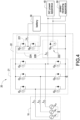
- FIG. 4 shows a block circuit diagram of a charger in FIG. 3 according to a first embodiment of the present disclosure.
- the front-end bridge arm 221 includes a first switch Q 7 and a second switch Qs.
- a common-connected node of the first switch Q 7 and the second switch Q 8 is coupled to a first end of the first energy-storing inductor L 4 , and a second end of the first energy-storing inductor L 4 is coupled to the battery 30.
- the sub path 222 includes a third switch Q 9 .
- a first end of the third switch Q 9 is coupled to an end, which is not commonly coupled to the upper switch Q 5 , of the lower switch Q 6 , and a second end of the third switch Q 9 is coupled to the DC power apparatus 40.
Landscapes
- Engineering & Computer Science (AREA)
- Power Engineering (AREA)
- Transportation (AREA)
- Mechanical Engineering (AREA)
- Charge And Discharge Circuits For Batteries Or The Like (AREA)
- Electric Propulsion And Braking For Vehicles (AREA)
- Inverter Devices (AREA)
Abstract
Description
- The present disclosure relates to a power integration system, and more particularly to a power integration system with motor drive and battery charging and discharging.
- The statements in this section merely provide background information related to the present disclosure and do not necessarily constitute prior art.
- The current light electric vehicle system includes a motor driver and a charger, wherein the charger is divided into the on-board charger and the off-board charger. Since the chargers have different battery specifications, various manufacturers will introduce dedicated off-board chargers for users to use, and the disadvantage is that the chargers are not compatible with different vehicles, which makes it inconvenient to carry.
- An objective of the present disclosure is to provide a power integration system with motor drive and battery charging and discharging function to solve the problems of existing technology.
- In order to achieve the above-mentioned objective, the power integration system with motor drive and battery charging and discharging function includes a motor, a power integration circuit, and a battery. The power integration circuit includes an inverter and a charger. The inverter includes multi-phase bridge arms. Each bridge arm includes an upper switch and a lower switch, and each bridge is correspondingly coupled to each phase winding of the motor. The charger includes a front-end DC conversion path, and the upper switch and the lower switch of at least one bridge arm of the shared inverter. The battery is coupled to the power integration circuit. The power integration circuit receives a DC power provided by a DC power apparatus, and the charger converts the DC power to charge the battery, and the battery provides power required to drive the motor through the inverter.
- In one embodiment, the battery provides power required by a power-receiving apparatus through the charger, or the power-receiving apparatus charges the battery through the charger.
- In one embodiment, the front-end DC conversion path includes a front-end bridge arm and a first energy-storing inductor. The front-end bridge arm is coupled to the shared upper switch and lower switch. The first energy-storing inductor is coupled to the front-end bridge arm. The charger further includes a charging unit. The charging unit includes a second energy-storing inductor and a sub path. The second energy-storing inductor is coupled to the shared upper switch and lower switch. The sub path is coupled to the second energy-storing inductor.
- In one embodiment, the front-end bridge arm includes a first switch and a second switch. A common-connected node of the first switch and the second switch is coupled to a first end of the first energy-storing inductor, and a second end of the first energy-storing inductor is coupled to the battery. The sub path includes a third switch. A first end of the third switch is coupled to an end, which is not commonly coupled to the upper switch, of the lower switch, and a second end of the third switch is coupled to the DC power apparatus.
- In one embodiment, the front-end bridge arm includes a first switch and a second switch. A common-connected node of the first switch and the second switch is coupled to a first end of the first energy-storing inductor, and a second end of the first energy-storing inductor is coupled to the battery. The sub path includes a third switch. A first end of the third switch is coupled in series to the second energy-storing inductor, and a second end of the third switch is coupled to the DC power apparatus.
- In one embodiment, the front-end bridge arm includes a first switch and a second switch. A common-connected node of the first switch and the second switch is coupled to a first end of the first energy-storing inductor, and a second end of the first energy-storing inductor is coupled to the battery. The sub path includes a first diode. An anode of the first diode is coupled to an end, which is not commonly coupled to the upper switch, of the lower switch, and a cathode of the first diode is coupled to the DC power apparatus.
- In one embodiment, when a voltage of the battery is greater than a reference voltage value, the charging unit operates in a boost mode to charge the battery, and when the voltage of the battery is less than the reference voltage value, the charging unit operates in a buck mode to charge the battery.
- In one embodiment, the battery provides power required by a power-receiving apparatus through the charger, or the power-receiving apparatus charges the battery through the charger, and according to the power required by the power-receiving apparatus, the charging unit makes the battery operate in a boost mode or a buck mode to discharge to the power-receiving apparatus.
- In one embodiment, the front-end DC conversion path includes a front-end bridge arm and a first energy-storing inductor. The front-end bridge arm is coupled to the shared upper switch and lower switch. The first energy-storing inductor is coupled to the front-end bridge arm. The charger further includes a charging unit. The charging unit includes a plurality of second energy-storing inductors and a sub path. The second energy-storing inductors are correspondingly coupled to the shared upper switches and lower switches. The sub path is coupled to the second energy-storing inductors.
- Accordingly, the power integration system with motor drive and battery charging and discharging function is provided to realize the structure that the power switches of a three-phase motor driver are shared in the charger, which can reduce the number of external components, thereby reducing the size and achieving high efficiency.
- It is to be understood that both the foregoing general description and the following detailed description are exemplary, and are intended to provide further explanation of the present disclosure as claimed. Other advantages and features of the present disclosure will be apparent from the following description, drawings and claims.
- The present disclosure can be more fully understood by reading the following detailed description of the embodiment, with reference made to the accompanying drawing as follows:
-
FIG. 1 is a block diagram of a power integration system with motor drive and battery charging and discharging function used with a DC power apparatus and a power-receiving apparatus according to the present disclosure. -
FIG. 2 is a block diagram of the power integration system with motor drive and battery charging and discharging function used with the DC power apparatus according to the present disclosure. -
FIG. 3 is a block circuit diagram of the power integration system with motor drive and battery charging and discharging function according to a first embodiment of the present disclosure. -
FIG. 4 is a block circuit diagram of a charger inFIG. 3 according to a first embodiment of the present disclosure. -
FIG. 5 is a block circuit diagram of the charger inFIG. 3 according to a second embodiment of the present disclosure. -
FIG. 6 is a block circuit diagram of the charger inFIG. 3 according to a third embodiment of the present disclosure. -
FIG. 7 is a block circuit diagram of the power integration system with motor drive and battery charging and discharging function according to a second embodiment of the present disclosure. - Reference will now be made to the drawing figures to describe the present disclosure in detail. It will be understood that the drawing figures and exemplified embodiments of present disclosure are not limited to the details thereof.
- Due to the versatility of Type-C transmission cables and the convenience of USB-PD chargers, the present disclosure proposes an integrated (shared components) bidirectional charger structure as shown in
FIG. 1 , which combines the traditional three-phase motor driver and charger to form an integration system. The system can be directly connected to an external USB-PD through a Type-C transmission line for charging. In addition to the charging function, the battery energy can also be provided to external apparatuses (or power-receiving apparatuses) through Type-C transmission cables, such as but not limited to light electric vehicles (such as electric scooters, electric bicycles, electric wheelchairs, electric skateboards, etc.). Accordingly, the power integration system with motor drive and battery charging and discharging function is provided to realize the structure that the power switches of a three-phase motor driver are shared in the charger, which can reduce the number of external components, thereby reducing the size and achieving high efficiency. - Please refer to
FIG. 1 , which shows a block diagram of a power integration system with motor drive and battery charging and discharging function used with a DC power apparatus and a power-receiving apparatus according to the present disclosure. The power integration system with motor drive and battery charging and discharging function (hereinafter referred to as the power integration system) includes amotor 10, apower integration circuit 20, and abattery 30. Thepower integration circuit 20 includes aninverter 21 and acharger 22. Theinverter 21 has multi-phase (for example, three-phase) bridge arms, each phase bridge arm includes an upper switch and a lower switch, and each phase bridge arm is correspondingly coupled to each phase winding of themotor 10. Thecharger 22 includes a front-endDC conversion path 22A and the upper switch and the lower switch of at least one bridge arm of the sharedinverter 21. In other words, thepower integration circuit 20 is a shared-component circuit structure having theinverter 21 and thecharger 22. Specifically, the part of the shared component is the upper switch and the lower switch of the at least one bridge arm, and the front-endDC conversion path 22A, which will be described in detail later. Incidentally, the front-endDC conversion path 22A of the present disclosure can be, for example but not limited to, a boost converter, a buck converter, a buck-boost converter, or other types of DC-DC converters, which can be designed according to the requirements of practical applications. Thebattery 30 is coupled to thepower integration circuit 20. - The power integration system shown in
FIG. 1 is a bidirectional structure. Therefore, thepower integration circuit 20 receives DC power provided by aDC power apparatus 40, and thecharger 22 of thepower integration circuit 20 converts the DC power to charge thebattery 30 so that the DC power can charge thebattery 30. In one embodiment, theDC power apparatus 40 is, for example, but not limited to, USB-PD. Take the light electric vehicle - electric bicycle as an example, themotor 10, thepower integration circuit 20, and thebattery 30 are installed (disposed) inside the electric bicycle, and the DC power provided by theDC power apparatus 40 is an external USB-PD DC power. Therefore, when the electric bicycle is plugged into the USB-PD DC power for charging, thecharger 22 of thepower integration circuit 20 converts the USB-PD DC power to charge thebattery 30 installed inside the vehicle body of the electric bicycle. - Moreover, the
battery 30 provides power required by a power-receivingapparatus 50 through thecharger 22. As mentioned above, the power-receivingapparatus 50 is, for example, but not limited to, a portable mobile apparatus (such as a mobile phone, a tablet computer, a notebook computer, etc.). When the user is outdoors, the user can plug a mobile phone, a power bank, or an electric bicycle (i.e., the power-receiving apparatus 50) into thecharger 22 of thepower integration circuit 20 installed inside another electric bicycle for charging, thebattery 30 supplies (provides) the power required by the mobile phone through thecharger 22 to charge the mobile phone, the power bank, or the electric bicycle. - Moreover, the
battery 30 provides power required to drive themotor 10 through theinverter 21. When the user rides the electric bicycle outdoors, the power required to drive themotor 10 is supplied by thebattery 30. - Moreover, the power-receiving
apparatus 50 charges thebattery 30 through thecharger 22. When the electric bicycle is not in the riding state and no DC power (the USB-PD DC power) provided by theDC power apparatus 40 charges thebattery 30, thebattery 30 is charged by the power provided from the power-receiving apparatus 50 (i.e., the mobile phone, the power bank, or the electric bicycle). For example, when the user rides the electric bicycle outdoors and thebattery 30 cannot provide the power required by the electric bicycle, thebattery 30 can be charged by the power provided from the power-receivingapparatus 50 so that the electric bicycle can be ridden in a short time to the nearest place with theDC power apparatus 40 to be fully charged. - Therefore, the power integration system shown in
FIG. 1 provides a bidirectional power path, including that theDC power apparatus 40 charges thebattery 30 or the power-receivingapparatus 50 charging thebattery 30, and thebattery 30 supplies power to the power-receivingapparatus 50 or thebattery 30 supplies power to the motor. - Please refer to
FIG. 2 , which shows a block diagram of the power integration system with motor drive and battery charging and discharging function used with the DC power apparatus according to the present disclosure. The major difference between the embodiment shown inFIG. 2 and the embodiment shown inFIG. 1 is that the former does not have the power-receivingapparatus 50. In other words, the power integration system shown inFIG. 2 is applied (operated) without the power-receivingapparatus 50. Therefore, the power integration system shown inFIG. 2 provides a unidirectional power path, including theDC power apparatus 40 charging thebattery 30, and thebattery 30 supplying power to themotor 10. For other operations that are the same as those of the first embodiment shown inFIG. 1 , refer to the foregoing description, and the detail description is omitted here for conciseness. - Please refer to
FIG. 3 , which shows a block circuit diagram of the power integration system with motor drive and battery charging and discharging function according to a first embodiment of the present disclosure. The front-endDC conversion path 22A includes a front-end bridge arm 221 and a first energy-storing inductor L4. The front-end bridge arm 221 is coupled to the shared upper switch Qs and lower switch Q6. The first energy-storing inductor L4 is coupled to the front-end bridge arm 221. Thecharger 22 further includes acharging unit 22B. The chargingunit 22B includes a second energy-storing inductor L5 and asub path 222. - Please refer to
FIG. 4 , which shows a block circuit diagram of a charger inFIG. 3 according to a first embodiment of the present disclosure. The front-end bridge arm 221 includes a first switch Q7 and a second switch Qs. A common-connected node of the first switch Q7 and the second switch Q8 is coupled to a first end of the first energy-storing inductor L4, and a second end of the first energy-storing inductor L4 is coupled to thebattery 30. Thesub path 222 includes a third switch Q9. A first end of the third switch Q9 is coupled to an end, which is not commonly coupled to the upper switch Q5, of the lower switch Q6, and a second end of the third switch Q9 is coupled to theDC power apparatus 40. - Please refer to
FIG. 5 , which shows a block circuit diagram of the charger inFIG. 3 according to a second embodiment of the present disclosure. The front-end bridge arm 221 includes a first switch Q7 and a second switch Qs. A common-connected node of the first switch Q7 and the second switch Q8 is coupled to a first end of the first energy-storing inductor L4, and a second end of the first energy-storing inductor L4 is coupled to thebattery 30. Thesub path 222 includes a third switch Q9. A first end of the third switch Q9 is coupled in series to the second energy-storing inductor L5, and a second end of the third switch Q9 is coupled to theDC power apparatus 40. - Please refer to
FIG. 6 , which shows a block circuit diagram of the charger inFIG. 3 according to a third embodiment of the present disclosure. The front-end bridge arm 221 includes a first switch Q7 and a second switch Qs. A common-connected node of the first switch Q7 and the second switch Q8 is coupled to a first end of the first energy-storing inductor L4, and a second end of the first energy-storing inductor L4 is coupled to thebattery 30. Thesub path 222 includes a first diode D1. An anode of the first diode D1 is coupled to an end, which is not commonly coupled to the upper switch Q5, of the lower switch Q6, and a cathode of the first diode D1 is coupled to theDC power apparatus 40. - For the circuits shown in
FIG. 4 andFIG. 5 , when a voltage of thebattery 30 is greater than a reference voltage value, the chargingunit 22B operates in a boost mode to charge thebattery 30, and when the voltage of thebattery 30 is less than the reference voltage value, the chargingunit 22B operates in a buck (step-down) mode to charge thebattery 30. When the voltage of battery is equal to a reference voltage value, the chargingunit 22A provide the same voltage to charge the battery. Moreover, according to the power required by the power-receivingapparatus 50, the chargingunit 22B makes thebattery 30 operate in a boost (step-up) mode or a buck (step-down) mode to discharge to the power-receivingapparatus 50. For the circuit shown inFIG. 6 , the major difference betweenFIG. 4 ,FIG. 5 andFIG. 6 is that the chargingunit 22B operates in the boost (step-up) mode or the buck (step-down) mode to charge thebattery 30, but thebattery 30 cannot discharge to the power-receivingapparatus 50. - Moreover, the
battery 30 provides power required by the power-receivingapparatus 50 through thecharger 22, or the power-receivingapparatus 50 charges thebattery 30 through thecharger 22. Moreover, according to the power required by the power-receivingapparatus 50, the chargingunit 22B makes thebattery 30 operate in a boost (step-up) mode or a buck (step-down) mode to discharge to the power-receivingapparatus 50. - Please refer to
FIG. 7 , which shows a block circuit diagram of the power integration system with motor drive and battery charging and discharging function according to a second embodiment of the present disclosure. The front-endDC conversion path 22A includes a front-end bridge arm 221 and a first energy-storing inductor L4. The front-end bridge arm 221 is coupled to the shared upper switch Q5 and lower switch Q6. The first energy-storing inductor L4 is coupled to the front-end bridge arm 221. Thecharger 22 further includes acharging unit 22B. The chargingunit 22B includes a plurality of second energy-storing inductors L5 and asub path 222. The second energy-storing inductors L5 are correspondingly coupled to the shared upper switches Q3, Qs and lower switches Q4, Q6. Thesub path 222 is coupled to the second energy-storing inductors L5. In particular, the inductance value of each second energy-storing inductor L5 may be designed to be the same or different according to the actual requirements of the circuits. - For the circuit shown in
FIG. 7 , when a voltage of thebattery 30 is greater than a reference voltage value, the chargingunit 22B operates in a boost (step-up) mode to charge thebattery 30, and when the voltage of thebattery 30 is less than the reference voltage value, the chargingunit 22B operates in a buck (step-down) mode to charge thebattery 30. - Moreover, the
battery 30 provides power required by the power-receivingapparatus 50 through thecharger 22, or the power-receivingapparatus 50 charges thebattery 30 through thecharger 22. Moreover, according to the power required by the power-receivingapparatus 50, the chargingunit 22B makes thebattery 30 operate in a boost (step-up) mode or a buck (step-down) mode to discharge to the power-receivingapparatus 50. - Accordingly, the power integration system with motor drive and battery charging and discharging function is provided to realize the structure that the power switches of a three-phase motor driver are shared in the charger, which can reduce the number of external components, thereby reducing the size and achieving high efficiency.
Claims (11)
- A power integration system with motor drive and battery charging and discharging, characterized in that the power integration system comprising:a motor (10),a power integration circuit (20), comprising:an inverter (21), comprising multi-phase bridge arms, each bridge arm comprising an upper switch (Q1, Q3, Q5) and a lower switch (Q2, Q4, Q6), and each bridge correspondingly coupled to each phase winding of the motor (10), anda charger (22), comprising a front-end DC conversion path (22A), and the upper switch (Q1, Q3, Q5) and the lower switch (Q2, Q4, Q6) of at least one bridge arm of the shared inverter (21), anda battery (30), coupled to the power integration circuit (20),wherein the power integration circuit (20) receives a DC power provided by a DC power apparatus (40), and the charger (22) converts the DC power to charge the battery (30), and the battery (30) provides power required to drive the motor (10) through the inverter (21).
- The power integration system as claimed in claim 1, wherein the battery (30) provides power required by a power-receiving apparatus (50) through the charger (22), or the power-receiving apparatus (50) charges the battery (30) through the charger (22).
- The power integration system as claimed in claim 1, wherein the front-end DC conversion path (22A) comprises:a front-end bridge arm (221), coupled to the shared upper switch (Q1, Q3, Q5) and lower switch (Q2, Q4, Q6), anda first energy-storing inductor (L4), coupled to the front-end bridge arm (221),wherein the charger (22) further comprises:
a charging unit (22B), comprising:a second energy-storing inductor (L5), coupled to the shared upper switch (Q1, Q3, Q5) and lower switch (Q2, Q4, Q6), anda sub path (222), coupled to the second energy-storing inductor (L5). - The power integration system as claimed in claim 3, wherein the front-end bridge arm (221) comprises:a first switch (Q7) and a second switch (Q8), a common-connected node of the first switch (Q7) and the second switch (Q8) coupled to a first end of the first energy-storing inductor (L4), and a second end of the first energy-storing inductor (L4) coupled to the battery (30),wherein the sub path (222) comprises a third switch (Q9), a first end of the third switch (Q9) coupled to an end, which is not commonly coupled to the upper switch (Q1, Q3, Q5), of the lower switch (Q2, Q4, Q6), and a second end of the third switch (Q9) coupled to the DC power apparatus (40).
- The power integration system as claimed in claim 3, wherein the front-end bridge arm (221) comprises:a first switch (Q7) and a second switch (Q8), a common-connected node of the first switch (Q7) and the second switch (Q8) coupled to a first end of the first energy-storing inductor (L4), and a second end of the first energy-storing inductor (L4) coupled to the battery (30),wherein the sub path (222) comprises a third switch (Q9), a first end of the third switch (Q9) coupled in series to the second energy-storing inductor (L5), and a second end of the third switch (Q9) coupled to the DC power apparatus (40).
- The power integration system as claimed in claim 3, wherein the front-end bridge arm (221) comprises:a first switch (Q7) and a second switch (Q8), a common-connected node of the first switch (Q7) and the second switch (Q8) coupled to a first end of the first energy-storing inductor (L4), and a second end of the first energy-storing inductor (L4) coupled to the battery (30),wherein the sub path (222) comprises a first diode (Di), an anode of the first diode (Di) coupled to an end, which is not commonly coupled to the upper switch (Q1, Q3, Q5), of the lower switch (Q2, Q4, Q6), and a cathode of the first diode (Di) coupled to the DC power apparatus (40).
- The power integration system as claimed in claim 3, wherein when a voltage of the battery (30) is greater than a reference voltage value, the charging unit (22B) operates in a boost mode to charge the battery (30), and when the voltage of the battery (30) is less than the reference voltage value, the charging unit (22B) operates in a buck mode to charge the battery (30).
- The power integration system as claimed in claim 7, wherein the battery (30) provides power required by a power-receiving apparatus (50) through the charger (22), or the power-receiving apparatus (50) charges the battery (30) through the charger (22), and according to the power required by the power-receiving apparatus (50), the charging unit (22B) makes the battery (30) operate in a boost mode or a buck mode to discharge to the power-receiving apparatus (50).
- The power integration system as claimed in claim 1, wherein the front-end DC conversion path (22A) comprises:a front-end bridge arm (221), coupled to the shared upper switch (Q1, Q3, Q5) and lower switch (Q2, Q4, Q6), anda first energy-storing inductor (L4), coupled to the front-end bridge arm (221),wherein the charger (22) further comprises:
a charging unit (22B), comprising:a plurality of second energy-storing inductors (L5), correspondingly coupled to the shared upper switches (Q1, Q3, Q5) and lower switches (Q2, Q4, Q6), anda sub path (222), coupled to the second energy-storing inductors (L5). - The power integration system as claimed in claim 9, wherein when a voltage of the battery (30) is greater than a reference voltage value, the charging unit (22B) operates in a boost mode to charge the battery (30), and when the voltage of the battery (30) is less than the reference voltage value, the charging unit (22B) operates in a buck mode to charge the battery (30).
- The power integration system as claimed in claim 9, wherein the battery (30) provides power required by a power-receiving apparatus (50) through the charger (22), or the power-receiving apparatus (50) charges the battery (30) through the charger (22), and according to the power required by the power-receiving apparatus (50), the charging unit (22B) makes the battery (30) operate in a boost mode or a buck mode to discharge to the power-receiving apparatus (50).
Applications Claiming Priority (2)
| Application Number | Priority Date | Filing Date | Title |
|---|---|---|---|
| US202163276866P | 2021-11-08 | 2021-11-08 | |
| TW111135643A TWI862985B (en) | 2021-11-08 | 2022-09-21 | Power integration system with motor drive and battery charging and discharging |
Publications (1)
| Publication Number | Publication Date |
|---|---|
| EP4178072A1 true EP4178072A1 (en) | 2023-05-10 |
Family
ID=84329631
Family Applications (1)
| Application Number | Title | Priority Date | Filing Date |
|---|---|---|---|
| EP22205737.4A Pending EP4178072A1 (en) | 2021-11-08 | 2022-11-07 | Power integration system with motor drive and battery charging and discharging function |
Country Status (3)
| Country | Link |
|---|---|
| US (1) | US20230143231A1 (en) |
| EP (1) | EP4178072A1 (en) |
| JP (1) | JP7446390B2 (en) |
Families Citing this family (2)
| Publication number | Priority date | Publication date | Assignee | Title |
|---|---|---|---|---|
| CN120826941A (en) | 2023-04-21 | 2025-10-21 | 株式会社Ntt都科摩 | Terminal and communication method |
| CN120863381A (en) * | 2024-04-30 | 2025-10-31 | 华为数字能源技术有限公司 | All-in-one vehicle-mounted power supply device, power assembly and electric vehicle |
Citations (3)
| Publication number | Priority date | Publication date | Assignee | Title |
|---|---|---|---|---|
| US20190023136A1 (en) * | 2017-07-21 | 2019-01-24 | Hyundai Motor Company | Electric vehicle |
| US20190255953A1 (en) * | 2018-02-20 | 2019-08-22 | GM Global Technology Operations LLC | Onboard dc charging circuit using traction drive components |
| US20210091573A1 (en) * | 2019-09-20 | 2021-03-25 | Toyota Jidosha Kabushiki Kaisha | Power supply device |
Family Cites Families (85)
| Publication number | Priority date | Publication date | Assignee | Title |
|---|---|---|---|---|
| US5502368A (en) * | 1994-06-06 | 1996-03-26 | Ecoair Corp. | Hybrid alternator with voltage regulator |
| US5491622A (en) * | 1994-01-07 | 1996-02-13 | Delco Electronics Corp. | Power converter with emergency operating mode for three phase induction motors |
| US5500579A (en) * | 1995-01-03 | 1996-03-19 | Motorola, Inc. | Electric motor control with integral battery charger |
| JP3270984B2 (en) * | 1995-01-30 | 2002-04-02 | 京セラ株式会社 | Battery charger malfunction prevention circuit |
| US6037747A (en) * | 1997-10-15 | 2000-03-14 | Lucent Technologies Inc. | Mode selection circuit for a battery and method of operation thereof |
| US6518736B2 (en) * | 2000-06-26 | 2003-02-11 | Toyota Jidosha Kabushiki Kaisha | Mechanical power outputting apparatus and inverter apparatus |
| US6329796B1 (en) * | 2000-07-25 | 2001-12-11 | O2 Micro International Limited | Power management circuit for battery systems |
| JP2003259560A (en) * | 2002-02-28 | 2003-09-12 | Mitsumi Electric Co Ltd | Charging circuit |
| US6737830B2 (en) * | 2002-07-02 | 2004-05-18 | Hewlett-Packard Development Company, L.P. | Battery charging using a portable energy storage device |
| US7288918B2 (en) * | 2004-03-02 | 2007-10-30 | Distefano Michael Vincent | Wireless battery charger via carrier frequency signal |
| US7332881B2 (en) * | 2004-10-28 | 2008-02-19 | Textron Inc. | AC drive system for electrically operated vehicle |
| JP2007037275A (en) * | 2005-07-27 | 2007-02-08 | Hitachi Ltd | Motor drive device also serving as a charge control device |
| US9026211B2 (en) * | 2005-08-30 | 2015-05-05 | Boston Scientific Neuromodulation Corporation | Battery charger circuit for battery powered implantable neurostimulation systems |
| US7589986B2 (en) * | 2006-04-19 | 2009-09-15 | International Rectifier Corporation | Single stage integrated boost inverter motor drive circuit |
| ITMI20061438A1 (en) * | 2006-07-24 | 2008-01-25 | Campagnolo Srl | METHOD AND RECHARGING SYSTEM OF A BATTERY POWER UNIT |
| US8159078B2 (en) * | 2008-04-21 | 2012-04-17 | Black & Decker Inc. | Portable power driven equipment with internal combustion engine combined battery charging and starting circuit where the battery is a removable battery pack |
| WO2010131348A1 (en) * | 2009-05-14 | 2010-11-18 | トヨタ自動車株式会社 | Vehicle charging unit |
| WO2011013583A1 (en) * | 2009-07-27 | 2011-02-03 | 太陽誘電株式会社 | Motor drive device and electrically assisted vehicle provided therewith |
| US20110095728A1 (en) * | 2009-10-28 | 2011-04-28 | Superior Communications, Inc. | Method and apparatus for recharging batteries in a more efficient manner |
| KR101113415B1 (en) * | 2009-12-29 | 2012-03-02 | 삼성에스디아이 주식회사 | Protection Circuit for Battery Pack |
| US8575778B2 (en) * | 2010-01-12 | 2013-11-05 | Ford Global Technologies, Llc | Variable voltage converter (VVC) with integrated battery charger |
| US8704401B2 (en) * | 2010-03-03 | 2014-04-22 | Honda Motor Co., Ltd. | Vehicle electric power supply system |
| US8368355B2 (en) * | 2010-04-14 | 2013-02-05 | Apple Inc. | Portable electronic device power manager with current limit feedback control loop modification for stabilizing an external power supply |
| KR101760632B1 (en) * | 2010-05-19 | 2017-07-21 | 퀄컴 인코포레이티드 | Adaptive wireless energy transfer system |
| US9088224B2 (en) * | 2010-07-21 | 2015-07-21 | Lihua Chen | Variable voltage converter with stabilized output voltage |
| US9290097B2 (en) * | 2010-11-05 | 2016-03-22 | Robert Louis Steigerwald | Apparatus for transferring energy using onboard power electronics with high-frequency transformer isolation and method of manufacturing same |
| JP5817110B2 (en) * | 2010-12-08 | 2015-11-18 | ソニー株式会社 | Charge control device and charge control method |
| WO2012085992A1 (en) * | 2010-12-20 | 2012-06-28 | トヨタ自動車株式会社 | Electric vehicle and controlling method therefor |
| KR101203734B1 (en) * | 2011-04-08 | 2012-11-22 | 재단법인 포항산업과학연구원 | Integrated module of inverter and charger circuit |
| KR20120125886A (en) * | 2011-05-09 | 2012-11-19 | 재단법인 포항산업과학연구원 | integrated module of inverter and charger circuit |
| WO2013097824A1 (en) * | 2011-12-31 | 2013-07-04 | 深圳市比亚迪汽车研发有限公司 | Electric vehicle and power system and motor controller for electric vehicle |
| US9120390B2 (en) * | 2012-03-08 | 2015-09-01 | General Electric Company | Apparatus for transferring energy using onboard power electronics and method of manufacturing same |
| JP5664600B2 (en) * | 2012-06-27 | 2015-02-04 | トヨタ自動車株式会社 | Electric car |
| EP2928061B1 (en) * | 2012-11-28 | 2018-01-10 | Fuji Electric Co., Ltd. | Power conversion system and method for controlling same |
| US9520806B2 (en) * | 2012-12-04 | 2016-12-13 | Volvo Truck Corporation | Power supply device for supplying power to a load by combining a secondary battery and a capacitor |
| US9490710B2 (en) * | 2012-12-18 | 2016-11-08 | Volvo Truck Corporation | Power supply device for supplying power to a load by combining a secondary battery and a capacitor |
| JP6063762B2 (en) * | 2013-02-15 | 2017-01-18 | 日立オートモティブシステムズ株式会社 | Charger |
| US20140265945A1 (en) * | 2013-03-15 | 2014-09-18 | Infineon Technologies Austria Ag | Electric Drive System |
| US9559538B1 (en) * | 2013-03-15 | 2017-01-31 | Maxim Integrated Products, Inc. | Switch mode battery charger with improved battery charging time |
| US9914362B2 (en) * | 2013-04-15 | 2018-03-13 | Virginia Tech Intellectual Properties, Inc. | Energy storage for power factor correction in battery charger for electric-powered vehicles |
| JP5958449B2 (en) * | 2013-11-18 | 2016-08-02 | 株式会社デンソー | Power conversion system |
| US9783070B2 (en) * | 2014-02-14 | 2017-10-10 | Jabil Circuit, Inc. | Charge transfer system |
| JP5958494B2 (en) * | 2014-04-23 | 2016-08-02 | 株式会社デンソー | Switching control device |
| CN104065119B (en) * | 2014-06-04 | 2017-01-04 | 南京矽力杰半导体技术有限公司 | Battery feed circuit and method of supplying power to |
| CN107078682B (en) * | 2014-09-02 | 2019-09-10 | 日本精工株式会社 | Electric motor control device, electric power steering device and vehicle equipped with the same |
| DE102015101094A1 (en) * | 2015-01-27 | 2016-07-28 | Dr. Ing. H.C. F. Porsche Aktiengesellschaft | Charging control for a battery in a vehicle |
| JP2017529044A (en) * | 2015-06-01 | 2017-09-28 | グァンドン オッポ モバイル テレコミュニケーションズ コーポレーション リミテッド | Charging circuit and mobile terminal |
| BR112017027795B1 (en) * | 2015-06-23 | 2022-10-04 | Nissan Motor Co., Ltd | INVERTER WITH LOADING CAPACITY |
| JP6495783B2 (en) * | 2015-08-25 | 2019-04-03 | 太陽誘電株式会社 | Control device, power storage device and moving body |
| US11479139B2 (en) * | 2015-09-11 | 2022-10-25 | Invertedpower Pty Ltd | Methods and systems for an integrated charging system for an electric vehicle |
| US10562404B1 (en) * | 2015-10-05 | 2020-02-18 | University Of Maryland | Integrated onboard chargers for plug-in electric vehicles |
| CN105515094A (en) * | 2015-12-04 | 2016-04-20 | 合肥工业大学 | A battery management system charging wake-up circuit |
| KR101818168B1 (en) * | 2015-12-30 | 2018-02-21 | 주식회사 효성 | Battery management device and battery energy storing system |
| JP6438419B2 (en) * | 2016-01-25 | 2018-12-12 | 太陽誘電株式会社 | Drive device and electric assist device |
| US10071652B2 (en) * | 2016-05-11 | 2018-09-11 | Ford Global Technologies, Llc | Dual mode IGBT gate drive to reduce switching loss |
| US10778026B2 (en) * | 2016-09-23 | 2020-09-15 | Apple Inc. | Multi-phase buck-boost charger |
| KR102461367B1 (en) * | 2016-10-05 | 2022-10-31 | 볼투 모터 인코퍼레이티드 | electric vehicle |
| KR102441505B1 (en) * | 2017-12-11 | 2022-09-07 | 현대자동차주식회사 | How to charge a battery in an electric vehicle |
| US11332015B2 (en) * | 2017-12-15 | 2022-05-17 | Katlego Systems, Llc | Power supply charging system |
| WO2019153050A1 (en) * | 2018-02-09 | 2019-08-15 | AIQ Hybrid Pty Ltd | Hybrid powertrains |
| KR102523253B1 (en) * | 2018-03-21 | 2023-04-20 | 현대자동차주식회사 | Battery charger for electric vehicle |
| US11183864B2 (en) * | 2018-05-07 | 2021-11-23 | Apple Inc. | Multimode battery charging |
| US20210288506A1 (en) * | 2018-06-18 | 2021-09-16 | Shouichi Tanaka | Power system of electric vehicle |
| US10756648B2 (en) * | 2018-11-12 | 2020-08-25 | Ford Global Technologies, Llc | Inverter system with enhanced common source inductance generated at gate driver |
| US20200185927A1 (en) * | 2018-12-11 | 2020-06-11 | I/O Interconnect, Ltd. | Charging method and power supply device |
| US10790775B2 (en) * | 2019-02-01 | 2020-09-29 | Ford Global Technologies, Llc | Electric drive for electric vehicles |
| WO2021009217A2 (en) * | 2019-07-15 | 2021-01-21 | Eaton Intelligent Power Limited | Power distribution and circuit protection for a mobile application having a high efficiency inverter |
| CN112389270B (en) * | 2019-08-15 | 2022-07-15 | 比亚迪股份有限公司 | Energy conversion device and vehicle |
| CN112389348B (en) * | 2019-08-15 | 2022-12-09 | 比亚迪股份有限公司 | Electric vehicles and their integrated controllers, integrated control systems |
| EP4100271A4 (en) * | 2020-02-03 | 2024-03-13 | Wisk Aero LLC | ENERGY DISTRIBUTION CIRCUITS FOR ENERGY REGENERATION VEHICLES |
| KR102898388B1 (en) * | 2020-02-10 | 2025-12-10 | 엘지이노텍 주식회사 | Relay device and electric vehicle charging controller comprising the same |
| US12214684B2 (en) * | 2020-03-06 | 2025-02-04 | Zhejiang Hanmingbo New Energy Co., Ltd. | System and method for charging electric vehicles |
| KR102904692B1 (en) * | 2020-03-13 | 2025-12-29 | 엘지이노텍 주식회사 | Electric vehicle charging controller and apparatus for charging electric vehicle comprising the same |
| CN111682617A (en) * | 2020-06-22 | 2020-09-18 | 深圳市富兰瓦时技术有限公司 | A battery charging and discharging circuit |
| CN112937337B (en) * | 2021-01-21 | 2025-05-13 | 华为数字能源技术有限公司 | Charging system and electric vehicle |
| CN118508560A (en) * | 2021-01-21 | 2024-08-16 | 华为数字能源技术有限公司 | Power assembly, motor controller and electric vehicle compatible with boost-buck charging |
| CN112937332B (en) * | 2021-01-21 | 2025-05-13 | 华为数字能源技术有限公司 | Charging system and electric vehicle |
| WO2022198007A1 (en) * | 2021-03-18 | 2022-09-22 | Delta Electronics (Americas) Ltd. | Motor drive integrated on-board charger for electric vehicle and control method thereof |
| KR20220142796A (en) * | 2021-04-15 | 2022-10-24 | 현대자동차주식회사 | Charging device |
| CN115214834A (en) * | 2021-04-20 | 2022-10-21 | Sram德国有限公司 | Electric bicycle drive unit, bicycle frame for an electric bicycle drive unit, frame interface unit and energy accumulator device |
| CN115514027A (en) * | 2021-06-07 | 2022-12-23 | 创科无线普通合伙 | Circuit with balance charging and battery cell connection conversion functions |
| CN115917836B (en) * | 2021-08-05 | 2024-01-30 | 宁德时代新能源科技股份有限公司 | Charge and discharge circuits, systems and control methods |
| EP4156381A4 (en) * | 2021-08-05 | 2023-05-10 | Contemporary Amperex Technology Co., Limited | POWER BATTERY HEATER SYSTEM AND CONTROL METHOD AND CONTROL CIRCUIT THEREOF |
| US20230144929A1 (en) * | 2021-11-08 | 2023-05-11 | Delta Electronics, Inc. | Power integration system with motor drive and battery charging and discharging function |
| JP7578663B2 (en) * | 2021-11-08 | 2024-11-06 | 台達電子工業股▲ふん▼有限公司 | Power supply integration system with motor drive function and battery charge/discharge function |
-
2022
- 2022-11-07 JP JP2022178375A patent/JP7446390B2/en active Active
- 2022-11-07 US US17/981,560 patent/US20230143231A1/en active Pending
- 2022-11-07 EP EP22205737.4A patent/EP4178072A1/en active Pending
Patent Citations (3)
| Publication number | Priority date | Publication date | Assignee | Title |
|---|---|---|---|---|
| US20190023136A1 (en) * | 2017-07-21 | 2019-01-24 | Hyundai Motor Company | Electric vehicle |
| US20190255953A1 (en) * | 2018-02-20 | 2019-08-22 | GM Global Technology Operations LLC | Onboard dc charging circuit using traction drive components |
| US20210091573A1 (en) * | 2019-09-20 | 2021-03-25 | Toyota Jidosha Kabushiki Kaisha | Power supply device |
Also Published As
| Publication number | Publication date |
|---|---|
| JP2023070187A (en) | 2023-05-18 |
| US20230143231A1 (en) | 2023-05-11 |
| JP7446390B2 (en) | 2024-03-08 |
Similar Documents
| Publication | Publication Date | Title |
|---|---|---|
| EP4177100A2 (en) | Power integration system with motor drive and battery charging and discharging function | |
| US20230144929A1 (en) | Power integration system with motor drive and battery charging and discharging function | |
| CN110326183B (en) | Charging device and vehicle power supply unit | |
| CN101682199B (en) | Power distribution circuit for use in a portable telecommunications device | |
| US9643509B2 (en) | Apparatus and method for providing multi-voltage output of low voltage DC-DC converter of eco-friendly vehicle | |
| CN106476635A (en) | Hybrid system with multiple energy storing devices | |
| US9190908B2 (en) | Protection cover allowing handheld device to reversely discharge | |
| US11780342B2 (en) | On-board charging and discharging apparatus, charging and discharging system thereof, and electric vehicle | |
| CN115280658A (en) | Bidirectional DC-DC converter | |
| CN106143171A (en) | Multi-source energy storage system and energy management control method | |
| US20230143231A1 (en) | Power integration system with motor drive and battery charging and discharging function | |
| KR20220029522A (en) | Single stage ac-dc converter | |
| CN102820775A (en) | Integrated buck-boost converter of charging device | |
| WO2026092061A1 (en) | Circuit, charging device, and control method for circuit | |
| CN117578882B (en) | Control circuit and method for single-mode dual-current-path buck-boost converter | |
| TW202319266A (en) | Power integration system with motor drive and battery charging and discharging | |
| CN117791802B (en) | Active energy recovery battery equalization management system and method | |
| US11757352B2 (en) | Power conversion system for electrically driven mobility device and method for controlling same | |
| CN215647250U (en) | Wireless earphone and circuit, wireless earphone subassembly thereof | |
| CN223625625U (en) | Battery backup power supply circuit and system | |
| CN217514984U (en) | Driving and charging integrated circuit, charging and discharging integrated machine and electric automobile | |
| CN219554653U (en) | Multifunctional power supply device and vehicle | |
| CN116247925B (en) | A battery balancing bidirectional DC-DC converter | |
| CN120016626A (en) | Power supply circuit and power supply method | |
| JP2008301611A (en) | Power supply |
Legal Events
| Date | Code | Title | Description |
|---|---|---|---|
| PUAI | Public reference made under article 153(3) epc to a published international application that has entered the european phase |
Free format text: ORIGINAL CODE: 0009012 |
|
| STAA | Information on the status of an ep patent application or granted ep patent |
Free format text: STATUS: THE APPLICATION HAS BEEN PUBLISHED |
|
| AK | Designated contracting states |
Kind code of ref document: A1 Designated state(s): AL AT BE BG CH CY CZ DE DK EE ES FI FR GB GR HR HU IE IS IT LI LT LU LV MC ME MK MT NL NO PL PT RO RS SE SI SK SM TR |
|
| STAA | Information on the status of an ep patent application or granted ep patent |
Free format text: STATUS: REQUEST FOR EXAMINATION WAS MADE |
|
| 17P | Request for examination filed |
Effective date: 20231110 |
|
| RBV | Designated contracting states (corrected) |
Designated state(s): AL AT BE BG CH CY CZ DE DK EE ES FI FR GB GR HR HU IE IS IT LI LT LU LV MC ME MK MT NL NO PL PT RO RS SE SI SK SM TR |