EP4178059A1 - Power supply and method of operating the same - Google Patents
Power supply and method of operating the same Download PDFInfo
- Publication number
- EP4178059A1 EP4178059A1 EP21207051.0A EP21207051A EP4178059A1 EP 4178059 A1 EP4178059 A1 EP 4178059A1 EP 21207051 A EP21207051 A EP 21207051A EP 4178059 A1 EP4178059 A1 EP 4178059A1
- Authority
- EP
- European Patent Office
- Prior art keywords
- power supply
- output
- control unit
- bus
- electrical
- Prior art date
- Legal status (The legal status is an assumption and is not a legal conclusion. Google has not performed a legal analysis and makes no representation as to the accuracy of the status listed.)
- Granted
Links
Images



Classifications
-
- H—ELECTRICITY
- H02—GENERATION; CONVERSION OR DISTRIBUTION OF ELECTRIC POWER
- H02J—ELECTRIC POWER NETWORKS; CIRCUIT ARRANGEMENTS OR SYSTEMS FOR SUPPLYING OR DISTRIBUTING ELECTRIC POWER; SYSTEMS FOR STORING ELECTRIC ENERGY
- H02J1/00—Circuit arrangements for DC mains or DC distribution networks
- H02J1/10—Parallel operation of DC sources
-
- H—ELECTRICITY
- H02—GENERATION; CONVERSION OR DISTRIBUTION OF ELECTRIC POWER
- H02J—ELECTRIC POWER NETWORKS; CIRCUIT ARRANGEMENTS OR SYSTEMS FOR SUPPLYING OR DISTRIBUTING ELECTRIC POWER; SYSTEMS FOR STORING ELECTRIC ENERGY
- H02J1/00—Circuit arrangements for DC mains or DC distribution networks
- H02J1/10—Parallel operation of DC sources
- H02J1/102—Parallel operation of DC sources being switching converters
-
- H—ELECTRICITY
- H02—GENERATION; CONVERSION OR DISTRIBUTION OF ELECTRIC POWER
- H02J—ELECTRIC POWER NETWORKS; CIRCUIT ARRANGEMENTS OR SYSTEMS FOR SUPPLYING OR DISTRIBUTING ELECTRIC POWER; SYSTEMS FOR STORING ELECTRIC ENERGY
- H02J1/00—Circuit arrangements for DC mains or DC distribution networks
- H02J1/10—Parallel operation of DC sources
- H02J1/106—Parallel operation of DC sources for load balancing, symmetrisation, or sharing
-
- H—ELECTRICITY
- H02—GENERATION; CONVERSION OR DISTRIBUTION OF ELECTRIC POWER
- H02J—ELECTRIC POWER NETWORKS; CIRCUIT ARRANGEMENTS OR SYSTEMS FOR SUPPLYING OR DISTRIBUTING ELECTRIC POWER; SYSTEMS FOR STORING ELECTRIC ENERGY
- H02J1/00—Circuit arrangements for DC mains or DC distribution networks
- H02J1/10—Parallel operation of DC sources
- H02J1/109—Scheduling or re-scheduling the operation of the DC sources in a particular order, e.g. connecting or disconnecting the sources in sequential, alternating or in subsets, to meet a given demand
Definitions
- the present disclosure relates to supply of electrical power, and in particular, to a power supply and a method of operating the same.
- electrical output characteristics of power supplies may not always be adequate for required electrical input characteristics of electrical loads.
- a required load current may exceed a feasible supply current of a given power supply.
- the present disclosure aims to improve power supplies of the background art.
- a first aspect of the present disclosure relates to a power supply comprising a plurality of output ports, a respective power regulation unit connected to the respective output port, and a respective control unit connected to the respective power regulation unit.
- the respective power regulation unit is configured to independently regulate electrical output characteristics of the respective output port.
- the electrical output characteristics comprise an output voltage and an output current.
- a master of the control units is configured to issue target values for respective setpoint variables of the respective output port.
- the respective control unit is configured to set the respective setpoint variables and to adapt the set setpoint variable for one of its electrical output characteristics in dependence of a deviation of the other of its electrical output characteristics from its target value.
- the output ports may be interconnected in parallel, and the respective control unit may be configured to adapt the set setpoint variable for the respective output voltage in dependence of a deviation of the respective output current from its target value.
- the output ports may be interconnected in series, and the respective control unit may be configured to adapt the set setpoint variable for the respective output current in dependence of a deviation of the respective output voltage from its target value.
- the respective control unit may be configured to adapt the set setpoint variable for the one of its electrical output characteristics in accordance with a given sequence of the control units.
- the output ports may comprise one of: alternating-current, AC, output ports, and directed-current, DC, output ports.
- the respective control unit may comprise one of: a microcontroller, and a gate array logic.
- the power supply may further comprise a galvanic isolation between the control units.
- the power supply may further comprise communication means being designed to interconnect the control units across the galvanic isolation.
- the communication means may further be designed to interconnect the power regulation units.
- the communication means may comprise a bus being configured for real-time communication in less than a settling time of the power regulation units.
- the bus may comprise one of: a CAN bus, a MOST bus, and a LIN bus.
- the bus may comprise an optical bus.
- the bus may comprise an electrical bus including one or more of: an opto-coupler, and a capacitive coupling.
- a second aspect of the present disclosure relates to a method of operating a power supply.
- the power supply comprises: a plurality of output ports, a respective power regulation unit connected to the respective output port, and a respective control unit connected to the respective power regulation unit.
- the method comprises issuing, by a master of the control units, target values for respective setpoint variables for electrical output characteristics of the respective output port.
- the electrical output characteristics comprise an output voltage and an output current.
- the method further comprises setting the respective setpoint variables, independently regulating the electrical output characteristics of the respective output port, and adapting, by the respective control unit, the set setpoint variable for one of the electrical output characteristics in dependence of a deviation of the other of the electrical output characteristics from its target value.
- the present disclosure provides improved power supplies with less margin, higher efficiency, improved usability and a better power distribution/sharing among the supplies or channels, which also leads to better signal performance.
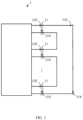
- FIG. 1 illustrates a power supply 1 in accordance with the present disclosure.
- the power supply 1 includes a plurality of individual supply channels with a structure akin to one another, which will be explained next.
- the power supply 1 comprises a plurality of output ports 11 (on the right in FIG. 1 ) respectively being indicated by pairs of terminals encircled by dotted lines.
- the respective pair of terminals may include plus (+) and minus (-)/earth poles.
- the output ports 11 may comprise one of: alternating-current (AC) output ports, and directed-current (DC) output ports.
- the power supply 1 may be an AC power supply or a DC power supply. A phase alignment among potential AC output ports is out of scope of the present disclosure, but may require further attention.
- the power supply 1 further comprises a respective power regulation unit 12 connected to the respective output port 11.
- the respective power regulation unit 12 is configured to independently regulate electrical output characteristics 13V, 13C of the respective output port 11, based on respective setpoint variables 15V, 15C and respective measured electrical output characteristics 13V, 13C of the respective output port 11.
- the electrical output characteristics 13V, 13C comprise an output voltage 13V and an output current 13C, and may be measured by the respective control loop or by external means connected to the respective output port 11.
- the power supply 1 further comprises a respective control unit 14 connected to the respective power regulation unit 12.
- the respective control unit 14 may comprise one of: a microcontroller, and a gate array logic, such as a field-programmable gate array (FPGA) or the like.
- a gate array logic such as a field-programmable gate array (FPGA) or the like.
- a master 14M of the control units 14 is configured to issue target values 17V, 17C for the respective setpoint variables 15V, 15C of the respective output port 11.
- the target values 17V, 17C may include a same target voltage V Load for the respective output port 11 and a same target current of I Load / N for the respective output port 11.
- the current sharing mode of operation involves an interconnection of the plurality of output ports 11 in parallel in accordance with FIG. 2 .
- the target values 17V, 17C may include a same target voltage V Load / N for the respective output port 11 and a same target current of I Load for the respective output port 11.
- the voltage sharing mode of operation involves an interconnection of the plurality of output ports 11 in series in accordance with FIG. 3 .
- the master 14M may be predetermined, or (s)elected on demand by the control units 14 in order to achieve redundancy in case the master 14M fails. In the latter case, the control units 14 may monitor each other in a similar manner as known from 'Hello' or 'Keepalive' network protocols.
- the respective control unit 14 is configured to set the respective setpoint variables 15V, 15C of the respective output port 11, as a notion for a control goal of the respective control loop.
- the respective control unit 14 is further configured to adapt the set setpoint variable 15V, 15C for one of its electrical output characteristics 13V, 13C in dependence of a deviation of the other of its electrical output characteristics 13C, 13V from its target value 17C, 17V.
- the respective control unit 14 is in the current sharing mode of operation further configured to adapt the set setpoint variable 15V - issued by the master 14M and set by the respective control unit 14 - for the respective output voltage 13V in dependence of a deviation of the respective (measured) output current 13C from its target value 17C.
- the channel relating to the master 14M is kept in constant voltage mode, while the channels relating to the other output ports 11 are kept in constant current mode.
- the respective control unit 14 is in the voltage sharing mode of operation further configured to adapt the set setpoint variable 15C - issued by the master 14M and set by the respective control unit 14 - for the respective output current 13C in dependence of a deviation of the respective (measured) output voltage 13V from its target value 17V. That is to say, the channel relating to the master 14M is kept in constant current mode, while the channels relating to the other output ports 11 are kept in constant voltage mode.
- the respective control unit 14 may be configured to adapt the set setpoint variable 15V, 15C for the one of its electrical output characteristics 13V, 13C in accordance with a given sequence of the control units 14, in order to prevent control problems.
- the sequence may be determined upon activation of a particular mode of operation of the power supply 1, or correspond to a structural arrangement of the plurality of channels within the power supply 1, such as "from left to right" or the like.
- the power supply 1 may further comprise a galvanic isolation 18 between the control units 14, in order to enable independent deployment of the plurality of channels of the power supply 1 as well.
- the power supply 1 may further comprise communication means 16 being designed to interconnect the control units 14 across the galvanic isolation 18, in order to coordinate an operation of the plurality of channels of the power supply 1. This is indicated by the arrowheads of block arrow 16 pointing to the left and down.
- the communication means 16 may further be designed to interconnect the power regulation units 12, in order to save a control time (i.e., minimize a delay) between the plurality of channels of the power supply 1. This is indicated by the arrowheads of block arrow 16 pointing to the right and down.
- the communication means 16 may comprise a bus being configured for real-time communication in less than a settling time of the power regulation units 12, in order to coordinate the operation of the plurality of channels of the power supply 1 at least as fast as the control loops (real-time ability).
- the bus may comprise one of: a CAN bus, a MOST bus, and a LIN bus, in order to use commercial off-the-shelf supplies as much as possible.
- the bus may comprise an optical bus, which is inherently designed to interconnect the control units 14 across the galvanic isolation 18.
- the bus may comprise an electrical bus including one or more of an opto-coupler and a capacitive coupling across a respective galvanic isolation 18.
- FIG. 2 illustrates the power supply 1 of FIG. 1 with parallel-interconnected output ports for current sharing.
- the output ports 11 may be interconnected in parallel so as to supply a sum I Load of the output currents 13C at a same output voltage 13V, V Load .
- the respective control unit 14 may be configured to adapt the set setpoint variable 15V for the respective output voltage 13V in dependence of a deviation of the respective output current 13C from its target value 17C.
- FIG. 3 illustrates the power supply 1 of FIG. 1 with serially-interconnected output ports for voltage sharing.
- the output ports 11 may be interconnected in series so as to supply a sum V Load of the output voltages 13V at a same output current 13C, I Load .
- the respective control unit 14 may be configured to adapt the set setpoint variable 15C for the respective output current 13C in dependence of a deviation of the respective output voltage 13V from its target value 17V.
- FIG. 4 illustrates a method 4 of operating the power supply 1 of FIG. 1 in accordance with the present disclosure.
- the underlying power supply 1 comprises: a plurality of output ports 11, a respective power regulation unit 12 connected to the respective output port 11, and a respective control unit 14 connected to the respective power regulation unit 12.
- the method 4 comprises issuing 41, by a master 14M of the control units 14, target values 17V, 17C for respective setpoint variables 15V, 15C for electrical output characteristics 13V, 13C of the respective output port 11.
- the electrical output characteristics 13V, 13C comprise an output voltage 13V and an output current 13C.
- the method 4 further comprises setting 42 the respective setpoint variables 15V, 15C.
- the method 4 further comprises independently regulating 43 the electrical output characteristics 13V, 13C of the respective output port 11.
- the method 4 further comprises adapting 44, by the respective control unit 14, the set setpoint variable 15V, 15C for one of the electrical output characteristics 13V, 13C in dependence of a deviation of the other of the electrical output characteristics 13C, 13V from its target value 17C, 17V.
Landscapes
- Engineering & Computer Science (AREA)
- Power Engineering (AREA)
- Direct Current Feeding And Distribution (AREA)
Abstract
Description
- The present disclosure relates to supply of electrical power, and in particular, to a power supply and a method of operating the same.
- Depending on the particular use case, electrical output characteristics of power supplies may not always be adequate for required electrical input characteristics of electrical loads. For example, a required load current may exceed a feasible supply current of a given power supply.
- This may mandate a deployment of larger and more expensive single power supplies for a sufficient margin, or a combination of a plurality of power supplies (or per se separate channels of a same power supply) to achieve the higher current. The latter may, however, be challenging since an interconnection of the plurality may interrelate the associated control loops and/or suffer from component tolerances. In other words, even supplies with a same part number will have slightly different electrical output characteristics, so that the one with e.g. the highest voltage will naturally source the most current. Accordingly, manual correction of settings may be required.
- In view of the drawbacks and limitations set out above, the present disclosure aims to improve power supplies of the background art.
- This objective is achieved by the embodiments as defined by the appended independent claims. Preferred embodiments are set forth in the dependent claims and in the following description and drawings.
- A first aspect of the present disclosure relates to a power supply comprising a plurality of output ports, a respective power regulation unit connected to the respective output port, and a respective control unit connected to the respective power regulation unit. The respective power regulation unit is configured to independently regulate electrical output characteristics of the respective output port. The electrical output characteristics comprise an output voltage and an output current. A master of the control units is configured to issue target values for respective setpoint variables of the respective output port. The respective control unit is configured to set the respective setpoint variables and to adapt the set setpoint variable for one of its electrical output characteristics in dependence of a deviation of the other of its electrical output characteristics from its target value.
- The output ports may be interconnected in parallel, and the respective control unit may be configured to adapt the set setpoint variable for the respective output voltage in dependence of a deviation of the respective output current from its target value.
- The output ports may be interconnected in series, and the respective control unit may be configured to adapt the set setpoint variable for the respective output current in dependence of a deviation of the respective output voltage from its target value.
- The respective control unit may be configured to adapt the set setpoint variable for the one of its electrical output characteristics in accordance with a given sequence of the control units.
- The output ports may comprise one of: alternating-current, AC, output ports, and directed-current, DC, output ports.
- The respective control unit may comprise one of: a microcontroller, and a gate array logic.
- The power supply may further comprise a galvanic isolation between the control units.
- The power supply may further comprise communication means being designed to interconnect the control units across the galvanic isolation.
- The communication means may further be designed to interconnect the power regulation units.
- The communication means may comprise a bus being configured for real-time communication in less than a settling time of the power regulation units.
- The bus may comprise one of: a CAN bus, a MOST bus, and a LIN bus.
- The bus may comprise an optical bus.
- The bus may comprise an electrical bus including one or more of: an opto-coupler, and a capacitive coupling.
- A second aspect of the present disclosure relates to a method of operating a power supply. The power supply comprises: a plurality of output ports, a respective power regulation unit connected to the respective output port, and a respective control unit connected to the respective power regulation unit. The method comprises issuing, by a master of the control units, target values for respective setpoint variables for electrical output characteristics of the respective output port. The electrical output characteristics comprise an output voltage and an output current. The method further comprises setting the respective setpoint variables, independently regulating the electrical output characteristics of the respective output port, and adapting, by the respective control unit, the set setpoint variable for one of the electrical output characteristics in dependence of a deviation of the other of the electrical output characteristics from its target value.
- By splitting a required electrical characteristic (current or voltage) of a load into smaller contributions of interconnected supplies (or channels thereof) - defined by target values for respective setpoint variables to be set - and by adapting the respective set setpoint variables in view of deviations of the smaller contributions from their target values, the present disclosure provides improved power supplies with less margin, higher efficiency, improved usability and a better power distribution/sharing among the supplies or channels, which also leads to better signal performance.
- The technical effects and advantages described in relation with the power supply equally apply to the method of operating the same having corresponding features.
- The above-described aspects and implementations will now be explained with reference to the accompanying drawings, in which the same or similar reference numerals designate the same or similar elements.
- The features of these aspects and implementations may be combined with each other unless specifically stated otherwise.
- The drawings are to be regarded as being schematic representations, and elements illustrated in the drawings are not necessarily shown to scale. Rather, the various elements are represented such that their function and general purpose become apparent to those skilled in the art.
-
FIG. 1 illustrates a power supply in accordance with the present disclosure; -
FIG. 2 illustrates the power supply ofFIG. 1 with parallel-interconnected output ports for current sharing; -
FIG. 3 illustrates the power supply ofFIG. 1 with serially-interconnected output ports for voltage sharing; and -
FIG. 4 illustrates a method of operating the power supply ofFIG. 1 in accordance with the present disclosure. -
FIG. 1 illustrates apower supply 1 in accordance with the present disclosure. - Generally, the
power supply 1 includes a plurality of individual supply channels with a structure akin to one another, which will be explained next. - The
power supply 1 comprises a plurality of output ports 11 (on the right inFIG. 1 ) respectively being indicated by pairs of terminals encircled by dotted lines. The respective pair of terminals may include plus (+) and minus (-)/earth poles. - The
output ports 11 may comprise one of: alternating-current (AC) output ports, and directed-current (DC) output ports. Correspondingly, thepower supply 1 may be an AC power supply or a DC power supply. A phase alignment among potential AC output ports is out of scope of the present disclosure, but may require further attention. - The
power supply 1 further comprises a respectivepower regulation unit 12 connected to therespective output port 11. - Based on respective control loops, the respective
power regulation unit 12 is configured to independently regulateelectrical output characteristics respective output port 11, based onrespective setpoint variables electrical output characteristics respective output port 11. Theelectrical output characteristics output voltage 13V and anoutput current 13C, and may be measured by the respective control loop or by external means connected to therespective output port 11. - The
power supply 1 further comprises arespective control unit 14 connected to the respectivepower regulation unit 12. - The
respective control unit 14 may comprise one of: a microcontroller, and a gate array logic, such as a field-programmable gate array (FPGA) or the like. - A master 14M of the
control units 14 is configured to issue target values 17V, 17C for therespective setpoint variables respective output port 11. - For example, given required electrical load characteristics VLoad, ILoad and current sharing among a plurality of N channels, the target values 17V, 17C may include a same target voltage VLoad for the
respective output port 11 and a same target current of ILoad /N for therespective output port 11. The current sharing mode of operation involves an interconnection of the plurality ofoutput ports 11 in parallel in accordance withFIG. 2 . - As a further example, given the required electrical load characteristics VLoad, ILoad and voltage sharing among a plurality of N channels, the target values 17V, 17C may include a same target voltage VLoad / N for the
respective output port 11 and a same target current of ILoad for therespective output port 11. The voltage sharing mode of operation involves an interconnection of the plurality ofoutput ports 11 in series in accordance withFIG. 3 . - The master 14M may be predetermined, or (s)elected on demand by the
control units 14 in order to achieve redundancy in case the master 14M fails. In the latter case, thecontrol units 14 may monitor each other in a similar manner as known from 'Hello' or 'Keepalive' network protocols. - The
respective control unit 14 is configured to set therespective setpoint variables respective output port 11, as a notion for a control goal of the respective control loop. - The
respective control unit 14 is further configured to adapt theset setpoint variable electrical output characteristics electrical output characteristics - As such, the
respective control unit 14 is in the current sharing mode of operation further configured to adapt the set setpoint variable 15V - issued by the master 14M and set by the respective control unit 14 - for therespective output voltage 13V in dependence of a deviation of the respective (measured) output current 13C from its target value 17C. Thus, the channel relating to the master 14M is kept in constant voltage mode, while the channels relating to theother output ports 11 are kept in constant current mode. By adapting theoutput voltage 13V of the channels relating to theother output ports 11 independently from one another, a symmetric current distribution on the plurality of N channels may be achieved. - Likewise, the
respective control unit 14 is in the voltage sharing mode of operation further configured to adapt the set setpoint variable 15C - issued by the master 14M and set by the respective control unit 14 - for the respective output current 13C in dependence of a deviation of the respective (measured)output voltage 13V from its target value 17V. That is to say, the channel relating to the master 14M is kept in constant current mode, while the channels relating to theother output ports 11 are kept in constant voltage mode. - The
respective control unit 14 may be configured to adapt theset setpoint variable electrical output characteristics control units 14, in order to prevent control problems. For example, the sequence may be determined upon activation of a particular mode of operation of thepower supply 1, or correspond to a structural arrangement of the plurality of channels within thepower supply 1, such as "from left to right" or the like. - The
power supply 1 may further comprise agalvanic isolation 18 between thecontrol units 14, in order to enable independent deployment of the plurality of channels of thepower supply 1 as well. - The
power supply 1 may further comprise communication means 16 being designed to interconnect thecontrol units 14 across thegalvanic isolation 18, in order to coordinate an operation of the plurality of channels of thepower supply 1. This is indicated by the arrowheads ofblock arrow 16 pointing to the left and down. - The communication means 16 may further be designed to interconnect the
power regulation units 12, in order to save a control time (i.e., minimize a delay) between the plurality of channels of thepower supply 1. This is indicated by the arrowheads ofblock arrow 16 pointing to the right and down. - The communication means 16 may comprise a bus being configured for real-time communication in less than a settling time of the
power regulation units 12, in order to coordinate the operation of the plurality of channels of thepower supply 1 at least as fast as the control loops (real-time ability). - The bus may comprise one of: a CAN bus, a MOST bus, and a LIN bus, in order to use commercial off-the-shelf supplies as much as possible.
- The bus may comprise an optical bus, which is inherently designed to interconnect the
control units 14 across thegalvanic isolation 18. Alternatively, the bus may comprise an electrical bus including one or more of an opto-coupler and a capacitive coupling across a respectivegalvanic isolation 18. -
FIG. 2 illustrates thepower supply 1 ofFIG. 1 with parallel-interconnected output ports for current sharing. - As suggested, the
output ports 11 may be interconnected in parallel so as to supply a sum ILoad of theoutput currents 13C at asame output voltage 13V, VLoad. - In accordance with the parallel interconnection of the plurality of
output ports 11, therespective control unit 14 may be configured to adapt theset setpoint variable 15V for therespective output voltage 13V in dependence of a deviation of the respective output current 13C from its target value 17C. -
FIG. 3 illustrates thepower supply 1 ofFIG. 1 with serially-interconnected output ports for voltage sharing. - Contrary to
FIG. 2 , theoutput ports 11 may be interconnected in series so as to supply a sum VLoad of theoutput voltages 13V at a same output current 13C, ILoad. - In accordance with the serial interconnection of the plurality of
output ports 11, therespective control unit 14 may be configured to adapt theset setpoint variable 15C for the respective output current 13C in dependence of a deviation of therespective output voltage 13V from its target value 17V. -
FIG. 4 illustrates a method 4 of operating thepower supply 1 ofFIG. 1 in accordance with the present disclosure. - The
underlying power supply 1 comprises: a plurality ofoutput ports 11, a respectivepower regulation unit 12 connected to therespective output port 11, and arespective control unit 14 connected to the respectivepower regulation unit 12. - The method 4 comprises issuing 41, by a master 14M of the
control units 14, target values 17V, 17C forrespective setpoint variables electrical output characteristics respective output port 11. Theelectrical output characteristics output voltage 13V and an output current 13C. - The method 4 further comprises setting 42 the
respective setpoint variables - The method 4 further comprises independently regulating 43 the
electrical output characteristics respective output port 11. - The method 4 further comprises adapting 44, by the
respective control unit 14, theset setpoint variable electrical output characteristics electrical output characteristics
Claims (14)
- A power supply (1), comprisinga plurality of output ports (11);a respective power regulation unit (12) connected to the respective output port (11) and configured to independently regulate electrical output characteristics (13V, 13C) of the respective output port (11), the electrical output characteristics (13V, 13C) comprising an output voltage (13V) and an output current (13C);a respective control unit (14) connected to the respective power regulation unit (12) and configured to set respective setpoint variables (15V, 15C) of the respective output port (11);a master (14M) of the control units (14) configured to issue target values (17V, 17C) for the respective setpoint variables (15V, 15C); andthe respective control unit (14) configured to adapt the set setpoint variable (15V, 15C) for one of its electrical output characteristics (13V, 13C) in dependence of a deviation of the other of its electrical output characteristics (13C, 13V) from its target value (17C, 17V).
- The power supply (1) of claim 1,the output ports (11) being interconnected in parallel; andthe respective control unit (14) configured to adapt the set setpoint variable (15V) for the respective output voltage (13V) in dependence of a deviation of the respective output current (13C) from its target value (17C).
- The power supply (1) of claim 1,the output ports (11) being interconnected in series; andthe respective control unit (14) configured to adapt the set setpoint variable (15C) for the respective output current (13C) in dependence of a deviation of the respective output voltage (13V) from its target value (17V).
- The power supply (1) of any one of the preceding claims,
the respective control unit (14) configured to adapt the set setpoint variable (15V, 15C) for the one of its electrical output characteristics (13V, 13C) in accordance with a given sequence of the control units (14). - The power supply (1) of any one of the preceding claims,
the output ports (11) comprising one of: alternating-current, AC, output ports, and directed-current, DC, output ports. - The power supply (1) of any one of the preceding claims,
the respective control unit (14) comprising one of: a microcontroller, and a gate array logic. - The power supply (1) of any one of the preceding claims, further comprising a galvanic isolation (18) between the control units (14).
- The power supply (1) of claim 7,
communication means (16) being designed to interconnect the control units (14) across the galvanic isolation (18). - The power supply (1) of claim 8,
the communication means (16) further being designed to interconnect the power regulation units (12). - The power supply (1) of claim 8 or claim 9,
the communication means (16) comprising a bus being configured for real-time communication in less than a settling time of the power regulation units (12). - The power supply (1) of claim 10,
the bus comprising one of a CAN bus, a MOST bus, and a LIN bus. - The power supply (1) of claim 10 or claim 11,
the bus comprising an optical bus. - The power supply (1) of claim 10 or claim 11,
the bus comprising an electrical bus including one or more of: an opto-coupler, and a capacitive coupling. - A method (4) of operating a power supply (1),the power supply (1) comprising:a plurality of output ports (11), a respective power regulation unit (12) connected to the respective output port (11), and a respective control unit (14) connected to the respective power regulation unit (12);the method (4) comprising:issuing (41), by a master (14M) of the control units (14), target values (17V, 17C) for respective setpoint variables (15V, 15C) for electrical output characteristics (13V, 13C) of the respective output port (11), the electrical output characteristics (13V, 13C) comprising an output voltage (13V) and an output current (13C); andsetting (42) the respective setpoint variables (15V, 15C);independently regulating (43) the electrical output characteristics (13V, 13C) of the respective output port (11);adapting (44), by the respective control unit (14), the set setpoint variable (15V, 15C) for one of the electrical output characteristics (13V, 13C) in dependence of a deviation of the other of the electrical output characteristics (13C, 13V) from its target value (17C, 17V).
Priority Applications (1)
| Application Number | Priority Date | Filing Date | Title |
|---|---|---|---|
| EP21207051.0A EP4178059B1 (en) | 2021-11-09 | 2021-11-09 | POWER SUPPLY SYSTEM AND METHOD FOR OPERATION OF IT |
Applications Claiming Priority (1)
| Application Number | Priority Date | Filing Date | Title |
|---|---|---|---|
| EP21207051.0A EP4178059B1 (en) | 2021-11-09 | 2021-11-09 | POWER SUPPLY SYSTEM AND METHOD FOR OPERATION OF IT |
Publications (2)
| Publication Number | Publication Date |
|---|---|
| EP4178059A1 true EP4178059A1 (en) | 2023-05-10 |
| EP4178059B1 EP4178059B1 (en) | 2026-07-01 |
Family
ID=78695483
Family Applications (1)
| Application Number | Title | Priority Date | Filing Date |
|---|---|---|---|
| EP21207051.0A Active EP4178059B1 (en) | 2021-11-09 | 2021-11-09 | POWER SUPPLY SYSTEM AND METHOD FOR OPERATION OF IT |
Country Status (1)
| Country | Link |
|---|---|
| EP (1) | EP4178059B1 (en) |
Citations (4)
| Publication number | Priority date | Publication date | Assignee | Title |
|---|---|---|---|---|
| EP0958645B1 (en) * | 1997-02-07 | 2001-10-17 | Siemens Aktiengesellschaft | Load balancing of several independently working modules of a power supply installation |
| US20040021441A1 (en) * | 2001-04-27 | 2004-02-05 | Masayuki Komiyama | Hybrid vehicle power control apparatus and hybrid construction equipment using the power control apparatus |
| US20140266131A1 (en) * | 2013-03-15 | 2014-09-18 | Infineon Technologies Austria Ag | Power Converter Circuit |
| DE102016205036A1 (en) * | 2016-03-24 | 2017-09-28 | Viessmann Werke Gmbh & Co Kg | Method for controlling a power supply system |
-
2021
- 2021-11-09 EP EP21207051.0A patent/EP4178059B1/en active Active
Patent Citations (4)
| Publication number | Priority date | Publication date | Assignee | Title |
|---|---|---|---|---|
| EP0958645B1 (en) * | 1997-02-07 | 2001-10-17 | Siemens Aktiengesellschaft | Load balancing of several independently working modules of a power supply installation |
| US20040021441A1 (en) * | 2001-04-27 | 2004-02-05 | Masayuki Komiyama | Hybrid vehicle power control apparatus and hybrid construction equipment using the power control apparatus |
| US20140266131A1 (en) * | 2013-03-15 | 2014-09-18 | Infineon Technologies Austria Ag | Power Converter Circuit |
| DE102016205036A1 (en) * | 2016-03-24 | 2017-09-28 | Viessmann Werke Gmbh & Co Kg | Method for controlling a power supply system |
Non-Patent Citations (1)
| Title |
|---|
| KUTLUAY K ET AL: "Digital control of universal telecommunication power supplies using dual 8-bit microcontrollers", CONFERENCE RECORD OF THE 2002 IEEE INDUSTRY APPLICATIONS CONFERENCE : 37TH IAS ANNUAL MEETING ; 13 - 18 OCTOBER 2002, PITTSBURGH, PENNSYLVANIA, USA; [CONFERENCE RECORD OF THE IEEE INDUSTRY APPLICATIONS CONFERENCE. IAS ANNUAL MEETING], IEEE SERVICE CE, vol. 2, 13 October 2002 (2002-10-13), pages 1197 - 1204, XP010610032, ISBN: 978-0-7803-7420-1, DOI: 10.1109/IAS.2002.1042710 * |
Also Published As
| Publication number | Publication date |
|---|---|
| EP4178059B1 (en) | 2026-07-01 |
Similar Documents
| Publication | Publication Date | Title |
|---|---|---|
| EP0851567B1 (en) | Multiparalleling system of voltage source power converters | |
| US9608450B2 (en) | Modular static converters with parallel or series architecture and decentralized modular control (DMC) | |
| US20120280571A1 (en) | Voltage compensation | |
| AU2020442203B2 (en) | Power supply system | |
| US8351229B2 (en) | Current sharing power system | |
| US5453643A (en) | Controllable compound voltage DC/AC transforming circuit | |
| CN114402519B (en) | DC/DC conversion system, power storage system, and control method of DC/DC converter | |
| CN107422776A (en) | Low difference voltage regulator | |
| US11990761B2 (en) | Power supply system with current sharing and method of current sharing the same | |
| US12051905B2 (en) | Power system | |
| US12143007B2 (en) | Method and system for balancing parallel DC/DC converters | |
| KR20210120096A (en) | Power generation devices and systems that track peak power | |
| CN115485968B (en) | Photovoltaic power generation system, power control method and combiner box | |
| CN101364772A (en) | Circuit arrangement for supplying electric energy to variable loads from three phases | |
| CN109149549A (en) | A kind of Bipolar DC power system layered structure and control method using multivoltage balanced device parallel connection | |
| KR102148514B1 (en) | A votage balancer with dc-dc converter function | |
| CN109921407B (en) | A secondary regulator, system and method for DC microgrid current distribution | |
| KR20210147315A (en) | DC-DC converter with serial input parallel output multi-cell structure and control method thereof | |
| US11011993B2 (en) | Power supply and medical system | |
| AU2019423646B2 (en) | Power supply system and method for controlling power supply system | |
| CN116865382B (en) | A discharge equalization control method and battery system | |
| CN110165655B (en) | Direct-current power supply parallel operation switching device | |
| EP4485794A1 (en) | Multiparallel variable frequency drive and control method thereof | |
| SU1621010A1 (en) | Device for controlling three-phase voltage | |
| US11292357B2 (en) | Intelligent current control apparatus |
Legal Events
| Date | Code | Title | Description |
|---|---|---|---|
| PUAI | Public reference made under article 153(3) epc to a published international application that has entered the european phase |
Free format text: ORIGINAL CODE: 0009012 |
|
| STAA | Information on the status of an ep patent application or granted ep patent |
Free format text: STATUS: THE APPLICATION HAS BEEN PUBLISHED |
|
| STAA | Information on the status of an ep patent application or granted ep patent |
Free format text: STATUS: REQUEST FOR EXAMINATION WAS MADE |
|
| AK | Designated contracting states |
Kind code of ref document: A1 Designated state(s): AL AT BE BG CH CY CZ DE DK EE ES FI FR GB GR HR HU IE IS IT LI LT LU LV MC MK MT NL NO PL PT RO RS SE SI SK SM TR |
|
| 17P | Request for examination filed |
Effective date: 20230425 |
|
| RBV | Designated contracting states (corrected) |
Designated state(s): AL AT BE BG CH CY CZ DE DK EE ES FI FR GB GR HR HU IE IS IT LI LT LU LV MC MK MT NL NO PL PT RO RS SE SI SK SM TR |
|
| P01 | Opt-out of the competence of the unified patent court (upc) registered |
Effective date: 20230525 |
|
| GRAP | Despatch of communication of intention to grant a patent |
Free format text: ORIGINAL CODE: EPIDOSNIGR1 |
|
| STAA | Information on the status of an ep patent application or granted ep patent |
Free format text: STATUS: GRANT OF PATENT IS INTENDED |
|
| RIC1 | Information provided on ipc code assigned before grant |
Ipc: H02J 1/10 20060101AFI20260319BHEP Ipc: H02J 1/102 20260101ALI20260319BHEP |
|
| INTG | Intention to grant announced |
Effective date: 20260420 |
|
| GRAS | Grant fee paid |
Free format text: ORIGINAL CODE: EPIDOSNIGR3 |
|
| GRAA | (expected) grant |
Free format text: ORIGINAL CODE: 0009210 |
|
| STAA | Information on the status of an ep patent application or granted ep patent |
Free format text: STATUS: THE PATENT HAS BEEN GRANTED |
|
| AK | Designated contracting states |
Kind code of ref document: B1 Designated state(s): AL AT BE BG CY CZ DE DK EE ES FI FR GB GR HR HU IS IT LT LU LV MC MK MT NL NO PL PT RO RS SE SI SK SM TR |
|
| RBV | Designated contracting states (corrected) |
Designated state(s): AL AT BE BG CY CZ DE DK EE ES FI FR GB GR HR HU IS IT LT LU LV MC MK MT NL NO PL PT RO RS SE SI SK SM TR |
|
| REG | Reference to a national code |
Ref country code: GB Ref legal event code: FG4D |
|
| REG | Reference to a national code |
Ref country code: DE Ref legal event code: R096 Ref document number: 602021056388 Country of ref document: DE |