EP4178045A1 - Connector, mating connector, and connector assembly - Google Patents
Connector, mating connector, and connector assembly Download PDFInfo
- Publication number
- EP4178045A1 EP4178045A1 EP22204416.6A EP22204416A EP4178045A1 EP 4178045 A1 EP4178045 A1 EP 4178045A1 EP 22204416 A EP22204416 A EP 22204416A EP 4178045 A1 EP4178045 A1 EP 4178045A1
- Authority
- EP
- European Patent Office
- Prior art keywords
- connector
- shielding shell
- wall
- mating
- connection
- Prior art date
- Legal status (The legal status is an assumption and is not a legal conclusion. Google has not performed a legal analysis and makes no representation as to the accuracy of the status listed.)
- Pending
Links
Images


Classifications
-
- H—ELECTRICITY
- H01—ELECTRIC ELEMENTS
- H01R—ELECTRICALLY-CONDUCTIVE CONNECTIONS; STRUCTURAL ASSOCIATIONS OF A PLURALITY OF MUTUALLY-INSULATED ELECTRICAL CONNECTING ELEMENTS; COUPLING DEVICES; CURRENT COLLECTORS
- H01R13/00—Details of coupling devices of the kinds covered by groups H01R12/70 or H01R24/00 - H01R33/00
- H01R13/648—Protective earth or shield arrangements on coupling devices, e.g. anti-static shielding
- H01R13/658—High frequency shielding arrangements, e.g. against EMI [Electro-Magnetic Interference] or EMP [Electro-Magnetic Pulse]
- H01R13/6581—Shield structure
- H01R13/6585—Shielding material individually surrounding or interposed between mutually spaced contacts
- H01R13/6588—Shielding material individually surrounding or interposed between mutually spaced contacts with through openings for individual contacts
-
- H—ELECTRICITY
- H01—ELECTRIC ELEMENTS
- H01R—ELECTRICALLY-CONDUCTIVE CONNECTIONS; STRUCTURAL ASSOCIATIONS OF A PLURALITY OF MUTUALLY-INSULATED ELECTRICAL CONNECTING ELEMENTS; COUPLING DEVICES; CURRENT COLLECTORS
- H01R13/00—Details of coupling devices of the kinds covered by groups H01R12/70 or H01R24/00 - H01R33/00
- H01R13/46—Bases; Cases
- H01R13/516—Means for holding or embracing insulating body, e.g. casing, hoods
- H01R13/518—Means for holding or embracing insulating body, e.g. casing, hoods for holding or embracing several coupling parts, e.g. frames
-
- H—ELECTRICITY
- H01—ELECTRIC ELEMENTS
- H01R—ELECTRICALLY-CONDUCTIVE CONNECTIONS; STRUCTURAL ASSOCIATIONS OF A PLURALITY OF MUTUALLY-INSULATED ELECTRICAL CONNECTING ELEMENTS; COUPLING DEVICES; CURRENT COLLECTORS
- H01R24/00—Two-part coupling devices, or either of their cooperating parts, characterised by their overall structure
- H01R24/38—Two-part coupling devices, or either of their cooperating parts, characterised by their overall structure having concentrically or coaxially arranged contacts
-
- H—ELECTRICITY
- H01—ELECTRIC ELEMENTS
- H01R—ELECTRICALLY-CONDUCTIVE CONNECTIONS; STRUCTURAL ASSOCIATIONS OF A PLURALITY OF MUTUALLY-INSULATED ELECTRICAL CONNECTING ELEMENTS; COUPLING DEVICES; CURRENT COLLECTORS
- H01R13/00—Details of coupling devices of the kinds covered by groups H01R12/70 or H01R24/00 - H01R33/00
- H01R13/62—Means for facilitating engagement or disengagement of coupling parts or for holding them in engagement
- H01R13/622—Screw-ring or screw-casing
-
- H—ELECTRICITY
- H01—ELECTRIC ELEMENTS
- H01R—ELECTRICALLY-CONDUCTIVE CONNECTIONS; STRUCTURAL ASSOCIATIONS OF A PLURALITY OF MUTUALLY-INSULATED ELECTRICAL CONNECTING ELEMENTS; COUPLING DEVICES; CURRENT COLLECTORS
- H01R13/00—Details of coupling devices of the kinds covered by groups H01R12/70 or H01R24/00 - H01R33/00
- H01R13/64—Means for preventing incorrect coupling
- H01R13/645—Means for preventing incorrect coupling by exchangeable elements on case or base
- H01R13/6456—Means for preventing incorrect coupling by exchangeable elements on case or base comprising keying elements at different positions along the periphery of the connector
-
- H—ELECTRICITY
- H01—ELECTRIC ELEMENTS
- H01R—ELECTRICALLY-CONDUCTIVE CONNECTIONS; STRUCTURAL ASSOCIATIONS OF A PLURALITY OF MUTUALLY-INSULATED ELECTRICAL CONNECTING ELEMENTS; COUPLING DEVICES; CURRENT COLLECTORS
- H01R2105/00—Three poles
-
- H—ELECTRICITY
- H01—ELECTRIC ELEMENTS
- H01R—ELECTRICALLY-CONDUCTIVE CONNECTIONS; STRUCTURAL ASSOCIATIONS OF A PLURALITY OF MUTUALLY-INSULATED ELECTRICAL CONNECTING ELEMENTS; COUPLING DEVICES; CURRENT COLLECTORS
- H01R2201/00—Connectors or connections adapted for particular applications
- H01R2201/26—Connectors or connections adapted for particular applications for vehicles
Definitions
- the present invention relates to a connector, a mating connector mated with the connector, and a connector assembly including the connector and the mating connector.
- each connector includes a shielding shell, a single insulator, and three terminals.
- a single accommodation cavity is formed in the shielding shell, the insulator is inserted into the single accommodation cavity of the shielding shell, and the three terminals are inserted into three insertion holes of the insulator respectively.
- the three terminals are located in the same accommodation cavity of the shielding shell, and the terminals are not separated by electromagnetic shielding, which leads to no separate electromagnetic shielding protection between the three terminals connected with the three-phase windings U, V and W of the permanent magnet motor, which is prone to mutual interference or even short circuit, resulting in loss of excitation and damage of the permanent magnet motor;
- the permanent magnet motor when the permanent magnet motor generates an arc, the arc is easy to flow through the connector, which will cause damage to the converter and other equipment connected to the connector.
- the present invention has been made to overcome or alleviate at least one aspect of the above mentioned disadvantages.
- a connector comprising: a first shielding shell, three first insulators and three first terminals.
- the first shielding shell comprises a first outer wall and two first partition walls.
- the two first partition walls separate an internal space enclosed by the first outer wall into three first insertion cavities electromagnetically separated from each other.
- the three first insulators are respectively inserted into three first insertion cavities of the first shielding shell.
- the three first terminals are respectively inserted into the three first insulators for electrical connection with three-phase windings of a permanent magnet motor.
- the first outer wall of the first shielding shell comprises of: a first top wall; a first bottom wall; and a pair of first side walls respectively connected to the left and right sides of the first top wall and the first bottom wall, the two first partition walls are connected between the first top wall and the first bottom wall.
- the first shielding shell further comprises a first rear end wall at its rear side
- the connector further comprises three first cables, which pass through the first rear end wall and extend into the three first insertion cavities respectively to electrically connect with the three first terminals respectively.
- the connector further comprises three first cable fixing heads, which seal and fix the three first cables to the first rear end wall of the first shielding shell respectively.
- the first insulator comprises of: a first outer cylinder; and a first inner cylinder, which is arranged in the first outer cylinder and connected to the first outer cylinder, the first outer cylinder is fixed to the inner side of the first insertion cavity, and the first terminal is inserted into a central through hole of the first inner cylinder.
- a first connection post is formed at each of four corners of the first insertion cavity, and a first threaded hole is formed in the first connection post;
- four first flange parts corresponding to four first connection posts are formed on the outer side of the first outer cylinder, and a first connection hole is formed in the first flange part;
- the first outer cylinder is fixed to the inner side of the first insertion cavity by a first screw which passes through the first connection hole and is threaded into the first threaded hole.
- a positioning slot is formed on the inner side of the first outer cylinder, and the positioning slot is suitable for mating with a positioning rib formed on a mating connector to ensure the correct mating of the connector and the mating machine.
- a first connection ear is formed on the outer surface of the front side of the first side wall, and the first connection ear is configured to be connected with a second connection ear of a mating connector by a threaded connection member, so as to maintain the connector and the mating connector in the mating state.
- connection base plate is formed on the outer surface of the bottom of the first side wall, the connection base plate is configured to be connected to a panel, so as to fix the connector to the panel.
- the connector further comprises a sealing ring, which is sleeved on the front end of the first shielding shell.
- the front end of the first shielding shell is adapted to be inserted into a second shielding shell of a mating connector; the sealing ring is adapted to be radially compressed between the first shielding shell and the second shielding shell to realize the sealing between the first shielding shell and the second shielding shell.
- a mating connector adapted to mate with the above connector, the mating connector comprises a second shielding shell, three second insulators and three second terminals.
- the second shielding shell comprises a second outer wall and two second partition walls.
- the two second partition walls separate an internal space enclosed by the second outer wall into three second insertion cavities electromagnetically separated from each other.
- the three second insulators are respectively inserted into the three second insertion cavities of the second shielding shell;
- the three second terminals are respectively inserted into the three second insulators for mating with the three first terminals of the connector.
- the second outer wall comprises of: a second top wall; a second bottom wall; and a pair of second side walls respectively connected to the left and right sides of the second top wall and the second bottom wall.
- the two second partition walls are connected between the second top wall and the second bottom wall.
- the second shielding shell further comprises a second rear end wall at its rear side
- the mating connector further comprises three second cables, which pass through the second rear end wall and extend into the three second insertion cavities respectively to electrically connect with the three second terminals respectively.
- the mating connector further comprises three second cable fixing heads which seal and fix the three second cables to the second rear end wall of the second shielding shell respectively.
- the second insulator comprises of: a second outer cylinder; and a second inner cylinder arranged in the second outer cylinder and connected to the second outer cylinder.
- the second outer cylinder is fixed to the inner surface of the second insertion cavity, and the second terminal is inserted into a central through hole of the second inner cylinder.
- a second connection post is formed at each of four corners of the second insertion cavity, and a second threaded hole is formed in the second connection post;
- four second flange parts corresponding to the four second connection posts are formed on the outer side of the second outer cylinder, and a second connection hole is formed in the second flange part;
- the second outer cylinder is fixed to the inner side of the second insertion cavity by a second screw which passes through the second connection hole and is threaded into the second threaded hole.
- a positioning rib is formed on the outer surface of the second outer cylinder, and the positioning rib is suitable for mating with the positioning slot formed on the connector, so as to ensure the correct mating of the connector and the mating machine.
- a second connection ear is formed on the outer surface of the front side of the second side wall, and the second connection ear is configured to be connected with the first connection ear of the connector by a threaded connection member, so as to maintain the connector and the mating connector in the mating state.
- a connector assembly comprises the above connector and the above mating connector which is mated with the connector.
- three insertion cavities separated from each other are formed in the shielding shell, and the three terminals are respectively accommodated in the three insertion cavities, so that mutual interference or even short circuit between the three terminals can be avoided, and the arc can be prevented from flowing through the connector, ensuring the safety of the permanent magnet motor and related electrical equipment connected to the terminals.
- a connector comprising: a first shielding shell, three first insulators and three first terminals.
- the first shielding shell comprises a first outer wall and two first partition walls.
- the two first partition walls separate an internal space enclosed by the first outer wall into three first insertion cavities electromagnetically separated from each other.
- the three first insulators are respectively inserted into three first insertion cavities of the first shielding shell.
- the three first terminals are respectively inserted into the three first insulators for electrical connection with three-phase windings of a permanent magnet motor.
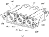
- Fig. 1 shows an illustrative view of a connector 10 according to an exemplary embodiment of the present invention
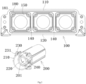
- Fig. 2 shows an exploded illustrative view of the first shielding housing 100 and the first insulator 200 of the connector 10 according to an exemplary embodiment of the present invention
- Fig. 6 shows a illustrative view of three-phase windings U, V, W of a permanent magnet motor M according to an exemplary embodiment of the present invention.
- the connector 10 includes a first shielding housing 100, three first insulators 200, and three first terminals 300.
- the first shielding shell 100 includes a first outer wall and two first partition walls 140.
- the two first partition walls 140 separate the internal space enclosed by the first outer wall into three first insertion cavities 101 electromagnetically separated from each other.
- the three first insulators 200 are respectively inserted into the three first insertion cavities 101 of the first shielding housing 100.
- the three first terminals 300 are respectively inserted into the three first insulators 200 for electrical connection with the three-phase windings U, V and W of the permanent magnet motor M.
- the three first terminals 300 can be electrically connected to the three-phase windings U, V, and W of the permanent magnet motor M through three cables (not shown).
- the first outer wall of the first shielding housing 100 includes a first top wall 110, a first bottom wall 120, and a pair of first side walls 130.
- the pair of first side walls 130 are respectively connected to the left and right sides of the first top wall 110 and the first bottom wall 120.
- Two first partition walls 140 are connected between the first top wall 110 and the first bottom wall 120.
- the first shielding shell 100 further comprises a first rear end wall 150 located at its rear side
- the connector 10 further comprises three first cables (not shown), which pass through the first rear end wall 150 and extend into the three first insertion cavities 101 respectively to electrically connect with the three first terminals 300 respectively.
- the connector 10 further comprises three first cable fixing heads 400, which respectively seal and fix the three first cables to the first rear end wall 150 of the first shielding housing 100.
- the first insulator 200 includes a first outer cylinder 210 and a first inner cylinder 220.
- the first inner cylinder 220 is arranged in the first outer cylinder 210 and connected to the first outer cylinder 210, the first outer cylinder 210 is fixed to the inner side of the first insertion cavity 101, and the first terminal 300 is inserted into the central through hole of the first inner cylinder 220.
- each first insulator 200 is an integrally formed part.
- a first connection post 180 is formed at each of four corners of the first insertion cavity 101, and a first threaded hole 181 is formed in the first connection post 180;
- Four first flange parts 230 corresponding to the four first connection posts 180 are formed on the outer side of the first outer cylinder 210, and a first connection hole 231 is formed in the first flange part 230.
- the first outer cylinder 210 is fixed to the inner side of the first insertion cavity 101 by a first screw 232 that passes through the first connection hole 231 and is threaded into the first threaded hole 181.
- a positioning slot 240 is formed on the inner side of the first outer cylinder 210, which is suitable for mating with the positioning rib 240' formed on the mating connector 10' (see Figures 4-5 ), so as to ensure the correct mating of the connector 10 and the mating machine 10'.
- a first connection ear 160 protruding outward is formed on the outer surface of the front side of the first side wall 130, and the first connection ear 160 is suitable for connecting with the second connection ear 160' of the mating connector 10' by the threaded connection member 162 (see Fig. 4-5 ), so as to maintain the connector 10 and the mating connector 10'in the mating state.
- connection base plate 170 protruding outward is formed on the outer surface of the bottom of the first side wall 130, and a slot hole 171 is formed on the connection base plate 170.
- the connection base plate 170 can be connected to a panel (E. G, a housing of an electrical device) through a connection member (E. G, a bolt) passing through the slot hole 171, so as to fix the connector 10 to the panel.
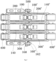
- Fig. 5 shows a sectional view of a connector assembly according to an exemplary embodiment of the present invention.
- the connector 10 further comprises a sealing ring 500, which is sleeved on the front end of the first shielding housing 100.
- the front end of the first shield housing 100 is adapted to be inserted into the second shield housing 100'of the mating connector 10'.
- the sealing ring 500 is adapted to be radially compressed between the first shield housing 100 and the second shield housing 100'to seal the gap between the two.
- Fig. 3 shows an illustrative view of the mating connector 10'according to an exemplary embodiment of the present invention
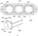
- Fig. 4 shows an exploded illustrative view of the second shield housing 100'and the second insulator 200' of the mating connector 10'according to an exemplary embodiment of the present invention.
- a mating connector 10' is also disclosed, which is suitable for mating with the aforementioned connector 10.
- the mating connector 10' includes a second shielding shell 100', three second insulators 200'and three second terminals 300'.
- the second shielding housing 100' includes a second outer wall and two second partition walls 140'.
- the three second insulators 200' are inserted into the three second insertion cavities 101' of the second shielding shell 100'respectively.
- the three second terminals 300' are respectively inserted into the three second insulators 200' for mating with the three first terminals 300 of the connector 10.
- one of the first terminal 300 and the second terminal 300' is a male terminal, and the other is a female terminal mated with the male terminal.
- the second outer wall includes a second top wall 110', a second bottom wall 120' and a pair of second side walls 130'.
- the pair of second side walls 130' are respectively connected to the left and right sides of the second top wall 110' and the second bottom wall 120', and two second partition walls 140' are connected between the second top wall 110'and the second bottom wall 120'.
- the second shielding shell 100'further comprises a second rear end wall 150' located at its rear side
- the mating connector 10'further comprises three second cables (not shown), which pass through the second rear end wall 150' and extend into the three second insertion cavities 101'respectively to electrically connect with the three second terminals 300' respectively.
- the mating connector 10'further comprises three second cable fixing heads 400', which seal and fix the three second cables to the second rear end wall 150'of the second shielding shell 100' respectively.
- the second insulator 200' includes a second outer cylinder 210' and a second inner cylinder 220'.
- the second inner cylinder 220' is arranged in the second outer cylinder 210' and connected to the second outer cylinder 210'.
- the second outer cylinder 210' is fixed to the inner side of the second insertion cavity 101', and the second terminal 300'is inserted into the central through hole of the second inner cylinder 220'.
- each second insulator 200' is an integral molded part.
- a second connection post 180' is formed at each of four corners of the second insertion cavity 101', and a second threaded hole 181'is formed in the second connection post 180';
- Four second flange parts 230'corresponding to the four second connection posts 180' are formed on the outer side of the second outer cylinder 210', and a second connection hole 231' is formed in the second flange part 230'.
- the second outer cylinder 210' is fixed to the inner side of the second insertion cavity 101' by a second screw 232'which passes through the second connection hole 231' and is threaded into the second threaded hole 181'.
- a positioning rib 240' is formed on the outer surface of the second outer cylinder 210', which is suitable for mating with the positioning slot 240 on the connector 10 to ensure the correct mating between the connector 10 and the mating machine 10'.
- a second connection ear 160'protruding outward is formed on the outer surface of the front side of the second side wall 130', which is suitable for connecting with the first connection ear 160 on the connector 10 by the threaded connection member 162, so as to maintain the connector 10 and the mating connector 10'in the mating state.
- a connector assembly is also disclosed, which includes the aforementioned connector 10 and the aforementioned mating connector 10'. Connector 10 and mating connector 10'are mated together.
Landscapes
- Details Of Connecting Devices For Male And Female Coupling (AREA)
Abstract
Description
- This application claims the benefit of Chinese Patent Application No.
CN202122669607.7 filed on November 3, 2021 - The present invention relates to a connector, a mating connector mated with the connector, and a connector assembly including the connector and the mating connector.
- In the prior art, two connectors that can be quickly mated are usually used between the permanent magnet motor and the AC power supply to realize the electrical connection between them. In the prior art, each connector includes a shielding shell, a single insulator, and three terminals. A single accommodation cavity is formed in the shielding shell, the insulator is inserted into the single accommodation cavity of the shielding shell, and the three terminals are inserted into three insertion holes of the insulator respectively. In the prior art, the three terminals are located in the same accommodation cavity of the shielding shell, and the terminals are not separated by electromagnetic shielding, which leads to no separate electromagnetic shielding protection between the three terminals connected with the three-phase windings U, V and W of the permanent magnet motor, which is prone to mutual interference or even short circuit, resulting in loss of excitation and damage of the permanent magnet motor; In addition, when the permanent magnet motor generates an arc, the arc is easy to flow through the connector, which will cause damage to the converter and other equipment connected to the connector.
- The present invention has been made to overcome or alleviate at least one aspect of the above mentioned disadvantages.
- According to an aspect of the present invention, there is provided a connector comprising: a first shielding shell, three first insulators and three first terminals. The first shielding shell comprises a first outer wall and two first partition walls. The two first partition walls separate an internal space enclosed by the first outer wall into three first insertion cavities electromagnetically separated from each other. The three first insulators are respectively inserted into three first insertion cavities of the first shielding shell. The three first terminals are respectively inserted into the three first insulators for electrical connection with three-phase windings of a permanent magnet motor.
- According to an exemplary embodiment of the present invention, the first outer wall of the first shielding shell comprises of: a first top wall; a first bottom wall; and a pair of first side walls respectively connected to the left and right sides of the first top wall and the first bottom wall, the two first partition walls are connected between the first top wall and the first bottom wall.
- According to another exemplary embodiment of the present invention, the first shielding shell further comprises a first rear end wall at its rear side, and the connector further comprises three first cables, which pass through the first rear end wall and extend into the three first insertion cavities respectively to electrically connect with the three first terminals respectively.
- According to another exemplary embodiment of the present invention, the connector further comprises three first cable fixing heads, which seal and fix the three first cables to the first rear end wall of the first shielding shell respectively.
- According to another exemplary embodiment of the present invention, the first insulator comprises of: a first outer cylinder; and a first inner cylinder, which is arranged in the first outer cylinder and connected to the first outer cylinder, the first outer cylinder is fixed to the inner side of the first insertion cavity, and the first terminal is inserted into a central through hole of the first inner cylinder.
- According to another exemplary embodiment of the present invention, a first connection post is formed at each of four corners of the first insertion cavity, and a first threaded hole is formed in the first connection post; four first flange parts corresponding to four first connection posts are formed on the outer side of the first outer cylinder, and a first connection hole is formed in the first flange part; the first outer cylinder is fixed to the inner side of the first insertion cavity by a first screw which passes through the first connection hole and is threaded into the first threaded hole.
- According to another exemplary embodiment of the present invention, a positioning slot is formed on the inner side of the first outer cylinder, and the positioning slot is suitable for mating with a positioning rib formed on a mating connector to ensure the correct mating of the connector and the mating machine.
- According to another exemplary embodiment of the present invention, a first connection ear is formed on the outer surface of the front side of the first side wall, and the first connection ear is configured to be connected with a second connection ear of a mating connector by a threaded connection member, so as to maintain the connector and the mating connector in the mating state.
- According to another exemplary embodiment of the present invention, a connection base plate is formed on the outer surface of the bottom of the first side wall, the connection base plate is configured to be connected to a panel, so as to fix the connector to the panel.
- According to another exemplary embodiment of the present invention, the connector further comprises a sealing ring, which is sleeved on the front end of the first shielding shell. The front end of the first shielding shell is adapted to be inserted into a second shielding shell of a mating connector; the sealing ring is adapted to be radially compressed between the first shielding shell and the second shielding shell to realize the sealing between the first shielding shell and the second shielding shell.
- According to another aspect of the present invention, there is provided a mating connector adapted to mate with the above connector, the mating connector comprises a second shielding shell, three second insulators and three second terminals. The second shielding shell comprises a second outer wall and two second partition walls. The two second partition walls separate an internal space enclosed by the second outer wall into three second insertion cavities electromagnetically separated from each other. The three second insulators are respectively inserted into the three second insertion cavities of the second shielding shell; The three second terminals are respectively inserted into the three second insulators for mating with the three first terminals of the connector.
- According to an exemplary embodiment of the present invention, the second outer wall comprises of: a second top wall; a second bottom wall; and a pair of second side walls respectively connected to the left and right sides of the second top wall and the second bottom wall. The two second partition walls are connected between the second top wall and the second bottom wall.
- According to another exemplary embodiment of the present invention, the second shielding shell further comprises a second rear end wall at its rear side, and the mating connector further comprises three second cables, which pass through the second rear end wall and extend into the three second insertion cavities respectively to electrically connect with the three second terminals respectively.
- According to another exemplary embodiment of the present invention, the mating connector further comprises three second cable fixing heads which seal and fix the three second cables to the second rear end wall of the second shielding shell respectively.
- According to another exemplary embodiment of the present invention, the second insulator comprises of: a second outer cylinder; and a second inner cylinder arranged in the second outer cylinder and connected to the second outer cylinder. The second outer cylinder is fixed to the inner surface of the second insertion cavity, and the second terminal is inserted into a central through hole of the second inner cylinder.
- According to another exemplary embodiment of the present invention, a second connection post is formed at each of four corners of the second insertion cavity, and a second threaded hole is formed in the second connection post; four second flange parts corresponding to the four second connection posts are formed on the outer side of the second outer cylinder, and a second connection hole is formed in the second flange part; the second outer cylinder is fixed to the inner side of the second insertion cavity by a second screw which passes through the second connection hole and is threaded into the second threaded hole.
- According to another exemplary embodiment of the present invention, a positioning rib is formed on the outer surface of the second outer cylinder, and the positioning rib is suitable for mating with the positioning slot formed on the connector, so as to ensure the correct mating of the connector and the mating machine.
- According to another exemplary embodiment of the present invention, a second connection ear is formed on the outer surface of the front side of the second side wall, and the second connection ear is configured to be connected with the first connection ear of the connector by a threaded connection member, so as to maintain the connector and the mating connector in the mating state.
- According to another aspect of the present invention, there is provided a connector assembly comprises the above connector and the above mating connector which is mated with the connector.
- In the above-mentioned exemplary embodiments according to the present invention, three insertion cavities separated from each other are formed in the shielding shell, and the three terminals are respectively accommodated in the three insertion cavities, so that mutual interference or even short circuit between the three terminals can be avoided, and the arc can be prevented from flowing through the connector, ensuring the safety of the permanent magnet motor and related electrical equipment connected to the terminals.
- The above and other features of the present invention will become more apparent by describing in detail exemplary embodiments thereof with reference to the accompanying drawings, in which:
-
Fig. 1 shows an illustrative view of a connector according to an exemplary embodiment of the present invention; -
Fig. 2 shows an exploded illustrative view of a first shielding shell and a first insulator of a connector according to an exemplary embodiment of the present invention; -
Fig. 3 shows an illustrative view of a mating connector according to an exemplary embodiment of the present invention; -
Fig. 4 shows an exploded illustrative view of a second shielding shell and a second insulator of a mating connector according to an exemplary embodiment of the present invention; -
Fig. 5 shows a sectional view of a connector assembly according to an exemplary embodiment of the present invention; and -
Fig. 6 shows an illustrative view of a three-phase winding of a permanent magnet motor according to an exemplary embodiment of the present invention. - Exemplary embodiments of the present disclosure will be described hereinafter in detail with reference to the attached drawings, wherein the like reference numerals refer to the like elements. The present disclosure may, however, be embodied in many different forms and should not be construed as being limited to the embodiment set forth herein; rather, these embodiments are provided so that the present disclosure will be thorough and complete, and will fully convey the concept of the disclosure to those skilled in the art.
- In the following detailed description, for purposes of explanation, numerous specific details are set forth in order to provide a thorough understanding of the disclosed embodiments. It will be apparent, however, that one or more embodiments may be practiced without these specific details. In other instances, well-known structures and devices are schematically shown in order to simplify the drawing.
- According to a general concept of the present invention, there is provided a connector comprising: a first shielding shell, three first insulators and three first terminals. The first shielding shell comprises a first outer wall and two first partition walls. The two first partition walls separate an internal space enclosed by the first outer wall into three first insertion cavities electromagnetically separated from each other. The three first insulators are respectively inserted into three first insertion cavities of the first shielding shell. The three first terminals are respectively inserted into the three first insulators for electrical connection with three-phase windings of a permanent magnet motor.
-
Fig. 1 shows an illustrative view of aconnector 10 according to an exemplary embodiment of the present invention;Fig. 2 shows an exploded illustrative view of thefirst shielding housing 100 and thefirst insulator 200 of theconnector 10 according to an exemplary embodiment of the present invention;Fig. 6 shows a illustrative view of three-phase windings U, V, W of a permanent magnet motor M according to an exemplary embodiment of the present invention. - As shown in
figures 1-2 and6 , in the illustrated embodiment, theconnector 10 includes afirst shielding housing 100, threefirst insulators 200, and threefirst terminals 300. Thefirst shielding shell 100 includes a first outer wall and twofirst partition walls 140. The twofirst partition walls 140 separate the internal space enclosed by the first outer wall into threefirst insertion cavities 101 electromagnetically separated from each other. The threefirst insulators 200 are respectively inserted into the threefirst insertion cavities 101 of thefirst shielding housing 100. The threefirst terminals 300 are respectively inserted into the threefirst insulators 200 for electrical connection with the three-phase windings U, V and W of the permanent magnet motor M. For example, the threefirst terminals 300 can be electrically connected to the three-phase windings U, V, and W of the permanent magnet motor M through three cables (not shown). - As shown in
FIGS. 1 and2 , in the illustrated embodiment, the first outer wall of thefirst shielding housing 100 includes a firsttop wall 110, a firstbottom wall 120, and a pair offirst side walls 130. The pair offirst side walls 130 are respectively connected to the left and right sides of the firsttop wall 110 and the firstbottom wall 120. Twofirst partition walls 140 are connected between the firsttop wall 110 and the firstbottom wall 120. - As shown in
Figures 1 and2 , in the illustrated embodiment, thefirst shielding shell 100 further comprises a firstrear end wall 150 located at its rear side, and theconnector 10 further comprises three first cables (not shown), which pass through the firstrear end wall 150 and extend into the threefirst insertion cavities 101 respectively to electrically connect with the threefirst terminals 300 respectively. - As shown in
Fig. 1 andFig. 2 , in the illustrated embodiment, theconnector 10 further comprises three first cable fixing heads 400, which respectively seal and fix the three first cables to the firstrear end wall 150 of thefirst shielding housing 100. - As shown in
FIGS. 1 and2 , in the illustrated embodiment, thefirst insulator 200 includes a firstouter cylinder 210 and a firstinner cylinder 220. The firstinner cylinder 220 is arranged in the firstouter cylinder 210 and connected to the firstouter cylinder 210, the firstouter cylinder 210 is fixed to the inner side of thefirst insertion cavity 101, and thefirst terminal 300 is inserted into the central through hole of the firstinner cylinder 220. In an exemplary embodiment of the present invention, eachfirst insulator 200 is an integrally formed part. - As shown in
Fig. 1 andFig. 2 , in the illustrated embodiment, afirst connection post 180 is formed at each of four corners of thefirst insertion cavity 101, and a first threadedhole 181 is formed in thefirst connection post 180; Fourfirst flange parts 230 corresponding to the four first connection posts 180 are formed on the outer side of the firstouter cylinder 210, and afirst connection hole 231 is formed in thefirst flange part 230. The firstouter cylinder 210 is fixed to the inner side of thefirst insertion cavity 101 by afirst screw 232 that passes through thefirst connection hole 231 and is threaded into the first threadedhole 181. - As shown in
Figure 1 andFigure 2 , in the illustrated embodiment, apositioning slot 240 is formed on the inner side of the firstouter cylinder 210, which is suitable for mating with the positioning rib 240' formed on the mating connector 10' (seeFigures 4-5 ), so as to ensure the correct mating of theconnector 10 and the mating machine 10'. - As shown in
Fig. 1 andFig. 2 , in the illustrated embodiment, afirst connection ear 160 protruding outward is formed on the outer surface of the front side of thefirst side wall 130, and thefirst connection ear 160 is suitable for connecting with the second connection ear 160' of the mating connector 10' by the threaded connection member 162 (seeFig. 4-5 ), so as to maintain theconnector 10 and the mating connector 10'in the mating state. - As shown in
Fig. 1 andFig. 2 , in the illustrated embodiment, aconnection base plate 170 protruding outward is formed on the outer surface of the bottom of thefirst side wall 130, and aslot hole 171 is formed on theconnection base plate 170. Theconnection base plate 170 can be connected to a panel (E. G, a housing of an electrical device) through a connection member (E. G, a bolt) passing through theslot hole 171, so as to fix theconnector 10 to the panel. -
Fig. 5 shows a sectional view of a connector assembly according to an exemplary embodiment of the present invention. - As shown in
figures 1-2 and5 , in the illustrated embodiment, theconnector 10 further comprises asealing ring 500, which is sleeved on the front end of thefirst shielding housing 100. The front end of thefirst shield housing 100 is adapted to be inserted into the second shield housing 100'of the mating connector 10'. The sealingring 500 is adapted to be radially compressed between thefirst shield housing 100 and the second shield housing 100'to seal the gap between the two. -
Fig. 3 shows an illustrative view of the mating connector 10'according to an exemplary embodiment of the present invention;Fig. 4 shows an exploded illustrative view of the second shield housing 100'and the second insulator 200' of the mating connector 10'according to an exemplary embodiment of the present invention. - As shown in
Figures 1 to 5 , in an exemplary embodiment of the present invention, a mating connector 10'is also disclosed, which is suitable for mating with theaforementioned connector 10. As shown infigures 3 and4 , the mating connector 10'includes a second shielding shell 100', three second insulators 200'and three second terminals 300'. - As shown in
Figures 1 to 5 , in the illustrated embodiment, the second shielding housing 100'includes a second outer wall and two second partition walls 140'. Two second partition walls 140'separate the internal space enclosed by the second outer wall into three second insertion cavities 101' electromagnetically separated from each other. The three second insulators 200'are inserted into the three second insertion cavities 101' of the second shielding shell 100'respectively. The three second terminals 300'are respectively inserted into the three second insulators 200' for mating with the threefirst terminals 300 of theconnector 10. In the illustrated embodiment, one of thefirst terminal 300 and the second terminal 300'is a male terminal, and the other is a female terminal mated with the male terminal. - As shown in
Figures 1 to 5 , in the illustrated embodiment, the second outer wall includes a second top wall 110', a second bottom wall 120' and a pair of second side walls 130'. The pair of second side walls 130'are respectively connected to the left and right sides of the second top wall 110' and the second bottom wall 120', and two second partition walls 140' are connected between the second top wall 110'and the second bottom wall 120'. - As shown in
Figures 1 to 5 , in the illustrated embodiment, the second shielding shell 100'further comprises a second rear end wall 150' located at its rear side, and the mating connector 10'further comprises three second cables (not shown), which pass through the second rear end wall 150' and extend into the three second insertion cavities 101'respectively to electrically connect with the three second terminals 300' respectively. - As shown in
Figures 1 to 5 , in the illustrated embodiment, the mating connector 10'further comprises three second cable fixing heads 400', which seal and fix the three second cables to the second rear end wall 150'of the second shielding shell 100' respectively. - As shown in
Figures 1 to 5 , in the illustrated embodiment, the second insulator 200'includes a second outer cylinder 210' and a second inner cylinder 220'. The second inner cylinder 220'is arranged in the second outer cylinder 210' and connected to the second outer cylinder 210'. The second outer cylinder 210'is fixed to the inner side of the second insertion cavity 101', and the second terminal 300'is inserted into the central through hole of the second inner cylinder 220'. In an exemplary embodiment of the present invention, each second insulator 200'is an integral molded part. - As shown in
Figures 1 to 5 , in the illustrated embodiment, a second connection post 180'is formed at each of four corners of the second insertion cavity 101', and a second threaded hole 181'is formed in the second connection post 180'; Four second flange parts 230'corresponding to the four second connection posts 180' are formed on the outer side of the second outer cylinder 210', and a second connection hole 231' is formed in the second flange part 230'. The second outer cylinder 210'is fixed to the inner side of the second insertion cavity 101' by a second screw 232'which passes through the second connection hole 231' and is threaded into the second threaded hole 181'. - As shown in
Figures 1 to 5 , in the illustrated embodiment, a positioning rib 240'is formed on the outer surface of the second outer cylinder 210', which is suitable for mating with thepositioning slot 240 on theconnector 10 to ensure the correct mating between theconnector 10 and the mating machine 10'. - As shown in
Figures 1 to 5 , in the illustrated embodiment, a second connection ear 160'protruding outward is formed on the outer surface of the front side of the second side wall 130', which is suitable for connecting with thefirst connection ear 160 on theconnector 10 by the threadedconnection member 162, so as to maintain theconnector 10 and the mating connector 10'in the mating state. - As shown in
Figures 1 to 5 , in an exemplary embodiment of the present invention, a connector assembly is also disclosed, which includes theaforementioned connector 10 and the aforementioned mating connector 10'.Connector 10 and mating connector 10'are mated together. - It should be appreciated for those skilled in this art that the above embodiments are intended to be illustrated, and not restrictive. For example, many modifications may be made to the above embodiments by those skilled in this art, and various features described in different embodiments may be freely combined with each other without conflicting in configuration or principle.
- Although several exemplary embodiments have been shown and described, it would be appreciated by those skilled in the art that various changes or modifications may be made in these embodiments without departing from the principles and spirit of the disclosure, the scope of which is defined in the claims and their equivalents.
- As used herein, an element recited in the singular and proceeded with the word "a" or "an" should be understood as not excluding plural of said elements or steps, unless such exclusion is explicitly stated. Furthermore, references to "one embodiment" of the present invention are not intended to be interpreted as excluding the existence of additional embodiments that also incorporate the recited features. Moreover, unless explicitly stated to the contrary, embodiments "comprising" or "having" an element or a plurality of elements having a particular property may include additional such elements not having that property.
Claims (15)
- A connector, comprising:a first shielding shell (100) comprises of:a first outer wall; andtwo first partition walls (140) which separate an internal space enclosed by the first outer wall into three first insertion cavities (101) electromagnetically separated from each other;three first insulators (200) respectively inserted into three first insertion cavities (101) of the first shielding shell (100); andthree first terminals (300) respectively inserted into the three first insulators (200) for electrical connection with three-phase windings (U, V, W) of a permanent magnet motor (M).
- The connector according to claim 1,wherein the first outer wall of the first shielding shell (100) comprises of:a first top wall (110);a first bottom wall (120); anda pair of first side walls (130) respectively connected to the left and right sides of the first top wall (110) and the first bottom wall (120),wherein the two first partition walls (140) are connected between the first top wall (110) and the first bottom wall (120).
- The connector according to claim 1,wherein the first shielding shell (100) further comprises a first rear end wall (150) at its rear side, and the connector (10) further comprises three first cables, which pass through the first rear end wall (150) and extend into the three first insertion cavities (101) respectively to electrically connect with the three first terminals (300) respectively;wherein the connector further comprises three first cable fixing heads (400), which seal and fix the three first cables to the first rear end wall (150) of the first shielding shell (100) respectively.
- The connector according to claim 1,wherein the first insulator (200) comprises of:a first outer cylinder (210); anda first inner cylinder (220), which is arranged in the first outer cylinder (210) and connected to the first outer cylinder (210),wherein the first outer cylinder (210) is fixed to the inner side of the first insertion cavity (101), and the first terminal (300) is inserted into a central through hole of the first inner cylinder (220).
- The connector according to claim 4,wherein a first connection post (180) is formed at each of four corners of the first insertion cavity (101), and a first threaded hole (181) is formed in the first connection post (180);wherein four first flange parts (230) corresponding to four first connection posts (180) are formed on the outer side of the first outer cylinder (210), and a first connection hole (231) is formed in the first flange part (230);wherein the first outer cylinder (210) is fixed to the inner side of the first insertion cavity (101) by a first screw (232) which passes through the first connection hole (231) and is threaded into the first threaded hole (181).
- The connector according to claim 4,
wherein a positioning slot (240) is formed on the inner side of the first outer cylinder (210), and the positioning slot (240) is suitable for mating with a positioning rib (240') formed on a mating connector (10') to ensure the correct mating of the connector (10) and the mating machine (10'). - The connector according to claim 2,
wherein a first connection ear (160) is formed on the outer surface of the front side of the first side wall (130), and the first connection ear (160) is configured to be connected with a second connection ear (160') of a mating connector (10') by a threaded connection member (162), so as to maintain the connector (10) and the mating connector (10') in the mating state. - The connector according to claim 2,
wherein a connection base plate (170) is formed on the outer surface of the bottom of the first side wall (130), the connection base plate (170) is configured to be connected to a panel, so as to fix the connector (10) to the panel. - The connector according to claim 1, further comprising:a sealing ring (500), which is sleeved on the front end of the first shielding shell (100),wherein the front end of the first shielding shell (100) is adapted to be inserted into a second shielding shell (100') of a mating connector (10');wherein the sealing ring (500) is adapted to be radially compressed between the first shielding shell (100) and the second shielding shell (100') to realize the sealing between the first shielding shell (100) and the second shielding shell (100').
- A mating connector adapted to mate with the connector (10) according to any one of claims 1-9, comprising:a second shielding shell (100') comprises of:a second outer wall; andtwo second partition walls (140') which separate an internal space enclosed by the second outer wall into three second insertion cavities (101') electromagnetically separated from each other;three second insulators (200') respectively inserted into the three second insertion cavities (101') of the second shielding shell (100'); andthree second terminals (300') respectively inserted into the three second insulators (200') for mating with the three first terminals (300) of the connector (10).
- The mating connector according to claim 10,wherein the second outer wall comprises of:a second top wall (110');a second bottom wall (120'); anda pair of second side walls (130') respectively connected to the left and right sides of the second top wall (110') and the second bottom wall (120'),wherein the two second partition walls (140') are connected between the second top wall (110') and the second bottom wall (120').
- The mating connector according to claim 10,wherein the second shielding shell (100') further comprises a second rear end wall (150') at its rear side, and the mating connector (10') further comprises three second cables, which pass through the second rear end wall (150') and extend into the three second insertion cavities (101') respectively to electrically connect with the three second terminals (300') respectively;wherein the mating connector (10') further comprises three second cable fixing heads (400') which seal and fix the three second cables to the second rear end wall (150') of the second shielding shell (100') respectively.
- The mating connector according to claim 10,wherein the second insulator (200') comprises of:a second outer cylinder (210'); anda second inner cylinder (220') arranged in the second outer cylinder (210') and connected to the second outer cylinder (210'),wherein the second outer cylinder (210') is fixed to the inner surface of the second insertion cavity (101'), and the second terminal (300') is inserted into a central through hole of the second inner cylinder (220').
- The mating connector according to claim 13,wherein a second connection post (180') is formed at each of four corners of the second insertion cavity (101'), and a second threaded hole (181') is formed in the second connection post (180');wherein four second flange parts (230') corresponding to the four second connection posts (180') are formed on the outer side of the second outer cylinder (210'), and a second connection hole (231') is formed in the second flange part (230');wherein the second outer cylinder (210') is fixed to the inner side of the second insertion cavity (101') by a second screw (232') which passes through the second connection hole (231') and is threaded into the second threaded hole (181').
- A connector assembly, comprising:the connector (10) according to any one of claims 1-9; andthe mating connector (10') according to any one of claims 10-14 which is mated with the connector (10).
Applications Claiming Priority (1)
| Application Number | Priority Date | Filing Date | Title |
|---|---|---|---|
| CN202122669607.7U CN216436204U (en) | 2021-11-03 | 2021-11-03 | Connector, mating connector and connector assembly |
Publications (1)
| Publication Number | Publication Date |
|---|---|
| EP4178045A1 true EP4178045A1 (en) | 2023-05-10 |
Family
ID=81335428
Family Applications (1)
| Application Number | Title | Priority Date | Filing Date |
|---|---|---|---|
| EP22204416.6A Pending EP4178045A1 (en) | 2021-11-03 | 2022-10-28 | Connector, mating connector, and connector assembly |
Country Status (2)
| Country | Link |
|---|---|
| EP (1) | EP4178045A1 (en) |
| CN (1) | CN216436204U (en) |
Citations (7)
| Publication number | Priority date | Publication date | Assignee | Title |
|---|---|---|---|---|
| US7854629B1 (en) * | 2010-01-19 | 2010-12-21 | Flowserve Management Company | Power plug system for submersible pump system |
| WO2016062652A1 (en) * | 2014-10-20 | 2016-04-28 | Multi-Holding Ag | Connector assembly |
| EP3211725A1 (en) * | 2016-02-24 | 2017-08-30 | Multi-Holding AG | Electrical connector |
| CN207426217U (en) * | 2017-10-26 | 2018-05-29 | 深圳市沃尔新能源电气科技股份有限公司 | Adaptor connector |
| CN207490235U (en) * | 2017-12-04 | 2018-06-12 | 南京康尼科技实业有限公司 | A kind of traction electric machine connector for middle low speed magnetic suspension train |
| WO2019193352A1 (en) * | 2018-04-05 | 2019-10-10 | Hypertac S.A. | Modular electromagnetic shielding housing |
| US20200335915A1 (en) * | 2019-04-19 | 2020-10-22 | Tm4 Inc. | Multi-phase connector for electric powertrain system |
-
2021
- 2021-11-03 CN CN202122669607.7U patent/CN216436204U/en active Active
-
2022
- 2022-10-28 EP EP22204416.6A patent/EP4178045A1/en active Pending
Patent Citations (7)
| Publication number | Priority date | Publication date | Assignee | Title |
|---|---|---|---|---|
| US7854629B1 (en) * | 2010-01-19 | 2010-12-21 | Flowserve Management Company | Power plug system for submersible pump system |
| WO2016062652A1 (en) * | 2014-10-20 | 2016-04-28 | Multi-Holding Ag | Connector assembly |
| EP3211725A1 (en) * | 2016-02-24 | 2017-08-30 | Multi-Holding AG | Electrical connector |
| CN207426217U (en) * | 2017-10-26 | 2018-05-29 | 深圳市沃尔新能源电气科技股份有限公司 | Adaptor connector |
| CN207490235U (en) * | 2017-12-04 | 2018-06-12 | 南京康尼科技实业有限公司 | A kind of traction electric machine connector for middle low speed magnetic suspension train |
| WO2019193352A1 (en) * | 2018-04-05 | 2019-10-10 | Hypertac S.A. | Modular electromagnetic shielding housing |
| US20200335915A1 (en) * | 2019-04-19 | 2020-10-22 | Tm4 Inc. | Multi-phase connector for electric powertrain system |
Also Published As
| Publication number | Publication date |
|---|---|
| CN216436204U (en) | 2022-05-03 |
Similar Documents
| Publication | Publication Date | Title |
|---|---|---|
| EP2858183A2 (en) | Connector joining structure | |
| US10164377B2 (en) | Plug connector and electrical connector assembly | |
| TWI674735B (en) | Female type connector for motor | |
| CN107240800B (en) | Connectors, connectors, mating connectors, mating connectors and connecting components | |
| JP7529353B2 (en) | Contact housings, electrical connectors, and electrical cable harnesses | |
| WO2016111539A1 (en) | Motor | |
| EP4207508A1 (en) | Connector housing assembly, connector and connector assembly | |
| EP0967688B1 (en) | Waterproof connector | |
| JP2013528311A (en) | Electrical connector | |
| US12224528B2 (en) | Connector and connector assembly | |
| CN216672020U (en) | Connector sealing assembly, connector and connector assembly | |
| CN114899636B (en) | Connector assembly suitable for energy storage system | |
| CN216698823U (en) | Hybrid connector | |
| US12170425B2 (en) | Connector and connector assembly | |
| CN211958127U (en) | Stable transmission radio frequency connector | |
| EP3719935B1 (en) | Connector housing and electrical connector | |
| KR20160092628A (en) | cable assembly for camera module | |
| CN216436204U (en) | Connector, mating connector and connector assembly | |
| CN208970826U (en) | Waterproof pushes and pulls self-locking connector | |
| KR20140059925A (en) | Terminal housing for motor and motor having the same of | |
| EP4343973A1 (en) | Connector assembly and electrical connection assembly | |
| CN210806121U (en) | Horizontal public head line end connector of port ethernet | |
| CN219843187U (en) | interface connector | |
| CN222952891U (en) | Transformer module structure and intelligent electrical switch | |
| CN223911605U (en) | A zero-sequence current transformer mounting structure for a miniature circuit breaker |
Legal Events
| Date | Code | Title | Description |
|---|---|---|---|
| PUAI | Public reference made under article 153(3) epc to a published international application that has entered the european phase |
Free format text: ORIGINAL CODE: 0009012 |
|
| STAA | Information on the status of an ep patent application or granted ep patent |
Free format text: STATUS: THE APPLICATION HAS BEEN PUBLISHED |
|
| AK | Designated contracting states |
Kind code of ref document: A1 Designated state(s): AL AT BE BG CH CY CZ DE DK EE ES FI FR GB GR HR HU IE IS IT LI LT LU LV MC ME MK MT NL NO PL PT RO RS SE SI SK SM TR |
|
| STAA | Information on the status of an ep patent application or granted ep patent |
Free format text: STATUS: REQUEST FOR EXAMINATION WAS MADE |
|
| 17P | Request for examination filed |
Effective date: 20231109 |
|
| RBV | Designated contracting states (corrected) |
Designated state(s): AL AT BE BG CH CY CZ DE DK EE ES FI FR GB GR HR HU IE IS IT LI LT LU LV MC ME MK MT NL NO PL PT RO RS SE SI SK SM TR |
|
| RAP1 | Party data changed (applicant data changed or rights of an application transferred) |
Owner name: SYSTEMES ET CONNECTIQUE DU MANS |
|
| STAA | Information on the status of an ep patent application or granted ep patent |
Free format text: STATUS: EXAMINATION IS IN PROGRESS |
|
| 17Q | First examination report despatched |
Effective date: 20250520 |