EP4178041A1 - An electric connector, an assembly and a method for detecting a state of a terminal lock - Google Patents
An electric connector, an assembly and a method for detecting a state of a terminal lock Download PDFInfo
- Publication number
- EP4178041A1 EP4178041A1 EP21206722.7A EP21206722A EP4178041A1 EP 4178041 A1 EP4178041 A1 EP 4178041A1 EP 21206722 A EP21206722 A EP 21206722A EP 4178041 A1 EP4178041 A1 EP 4178041A1
- Authority
- EP
- European Patent Office
- Prior art keywords
- electric connector
- bracket
- terminal lock
- control element
- opening
- Prior art date
- Legal status (The legal status is an assumption and is not a legal conclusion. Google has not performed a legal analysis and makes no representation as to the accuracy of the status listed.)
- Withdrawn
Links
- 238000000034 method Methods 0.000 title claims description 13
- 230000000903 blocking effect Effects 0.000 claims description 29
- 238000010586 diagram Methods 0.000 description 3
- 229910000831 Steel Inorganic materials 0.000 description 2
- 238000001514 detection method Methods 0.000 description 2
- 239000010959 steel Substances 0.000 description 2
- 230000008878 coupling Effects 0.000 description 1
- 238000010168 coupling process Methods 0.000 description 1
- 238000005859 coupling reaction Methods 0.000 description 1
- 238000003780 insertion Methods 0.000 description 1
- 230000037431 insertion Effects 0.000 description 1
- 230000007257 malfunction Effects 0.000 description 1
- 239000000463 material Substances 0.000 description 1
- 230000000007 visual effect Effects 0.000 description 1
Images



Classifications
-
- H—ELECTRICITY
- H01—ELECTRIC ELEMENTS
- H01R—ELECTRICALLY-CONDUCTIVE CONNECTIONS; STRUCTURAL ASSOCIATIONS OF A PLURALITY OF MUTUALLY-INSULATED ELECTRICAL CONNECTING ELEMENTS; COUPLING DEVICES; CURRENT COLLECTORS
- H01R13/00—Details of coupling devices of the kinds covered by groups H01R12/70 or H01R24/00 - H01R33/00
- H01R13/40—Securing contact members in or to a base or case; Insulating of contact members
- H01R13/42—Securing in a demountable manner
- H01R13/436—Securing a plurality of contact members by one locking piece or operation
- H01R13/4361—Insertion of locking piece perpendicular to direction of contact insertion
- H01R13/4362—Insertion of locking piece perpendicular to direction of contact insertion comprising a temporary and a final locking position
-
- H—ELECTRICITY
- H01—ELECTRIC ELEMENTS
- H01R—ELECTRICALLY-CONDUCTIVE CONNECTIONS; STRUCTURAL ASSOCIATIONS OF A PLURALITY OF MUTUALLY-INSULATED ELECTRICAL CONNECTING ELEMENTS; COUPLING DEVICES; CURRENT COLLECTORS
- H01R13/00—Details of coupling devices of the kinds covered by groups H01R12/70 or H01R24/00 - H01R33/00
- H01R13/64—Means for preventing incorrect coupling
- H01R13/641—Means for preventing incorrect coupling by indicating incorrect coupling; by indicating correct or full engagement
-
- H—ELECTRICITY
- H01—ELECTRIC ELEMENTS
- H01R—ELECTRICALLY-CONDUCTIVE CONNECTIONS; STRUCTURAL ASSOCIATIONS OF A PLURALITY OF MUTUALLY-INSULATED ELECTRICAL CONNECTING ELEMENTS; COUPLING DEVICES; CURRENT COLLECTORS
- H01R13/00—Details of coupling devices of the kinds covered by groups H01R12/70 or H01R24/00 - H01R33/00
- H01R13/73—Means for mounting coupling parts to apparatus or structures, e.g. to a wall
- H01R13/74—Means for mounting coupling parts in openings of a panel
- H01R13/741—Means for mounting coupling parts in openings of a panel using snap fastening means
- H01R13/745—Means for mounting coupling parts in openings of a panel using snap fastening means separate from the housing
-
- Y—GENERAL TAGGING OF NEW TECHNOLOGICAL DEVELOPMENTS; GENERAL TAGGING OF CROSS-SECTIONAL TECHNOLOGIES SPANNING OVER SEVERAL SECTIONS OF THE IPC; TECHNICAL SUBJECTS COVERED BY FORMER USPC CROSS-REFERENCE ART COLLECTIONS [XRACs] AND DIGESTS
- Y02—TECHNOLOGIES OR APPLICATIONS FOR MITIGATION OR ADAPTATION AGAINST CLIMATE CHANGE
- Y02T—CLIMATE CHANGE MITIGATION TECHNOLOGIES RELATED TO TRANSPORTATION
- Y02T10/00—Road transport of goods or passengers
- Y02T10/60—Other road transportation technologies with climate change mitigation effect
- Y02T10/70—Energy storage systems for electromobility, e.g. batteries
-
- Y—GENERAL TAGGING OF NEW TECHNOLOGICAL DEVELOPMENTS; GENERAL TAGGING OF CROSS-SECTIONAL TECHNOLOGIES SPANNING OVER SEVERAL SECTIONS OF THE IPC; TECHNICAL SUBJECTS COVERED BY FORMER USPC CROSS-REFERENCE ART COLLECTIONS [XRACs] AND DIGESTS
- Y02—TECHNOLOGIES OR APPLICATIONS FOR MITIGATION OR ADAPTATION AGAINST CLIMATE CHANGE
- Y02T—CLIMATE CHANGE MITIGATION TECHNOLOGIES RELATED TO TRANSPORTATION
- Y02T10/00—Road transport of goods or passengers
- Y02T10/60—Other road transportation technologies with climate change mitigation effect
- Y02T10/7072—Electromobility specific charging systems or methods for batteries, ultracapacitors, supercapacitors or double-layer capacitors
-
- Y—GENERAL TAGGING OF NEW TECHNOLOGICAL DEVELOPMENTS; GENERAL TAGGING OF CROSS-SECTIONAL TECHNOLOGIES SPANNING OVER SEVERAL SECTIONS OF THE IPC; TECHNICAL SUBJECTS COVERED BY FORMER USPC CROSS-REFERENCE ART COLLECTIONS [XRACs] AND DIGESTS
- Y02—TECHNOLOGIES OR APPLICATIONS FOR MITIGATION OR ADAPTATION AGAINST CLIMATE CHANGE
- Y02T—CLIMATE CHANGE MITIGATION TECHNOLOGIES RELATED TO TRANSPORTATION
- Y02T90/00—Enabling technologies or technologies with a potential or indirect contribution to GHG emissions mitigation
- Y02T90/10—Technologies relating to charging of electric vehicles
- Y02T90/14—Plug-in electric vehicles
Definitions
- the present disclosure relates to an electric connector, an assembly comprising the electric connector and a bracket, and a method for detecting a state of a terminal lock.
- a terminal lock or secondary lock may be provided on the electric connector.
- Electric connectors adapted to receive electric terminals may be used for example in vehicles, wherein safety aspects and product reliability require that a secondary lock is in a locked position to ensure that the electric terminals are locked in the electric connector.
- the present disclosure may be directed at an electric connector, wherein the electric connector comprises a plurality of cavities, wherein each cavity is designed to receive an electric terminal, a terminal lock mounted on the electric connector and adapted to lock each electric terminal in its cavity, wherein the terminal lock is moveable between an unlocked position and a locked position, and a control element moveable to detect the unlocked position and the locked position of the terminal lock.
- the electric connector may be a male or a female connector for coupling a cable.
- the electric connector may be used in a vehicle like a car or a truck to connect power cables or data cables.
- the cable may be connected to the electric connector by means of electric terminals.
- the electric connector comprises a plurality of cavities to receive a plurality of electric terminals.
- the terminal lock may be configured to fix or secure each electric terminal in its cavity.
- the terminal lock may be moved from the unlocked position into the locked position, wherein it is not be possible to remove the electric terminals out of the cavities or to insert the electric terminals into the cavities in the locked position.
- the terminal lock is in the unlocked position, it is possible to insert the electric terminals into the cavities or to remove the electric terminals from the cavities of the electric connector.
- the control element is adapted to detect an unlocked terminal lock, i.e. by means of the control element it is possible to detect the unlocked position of the electric connector. Thus, error indications or malfunctions may be avoided. Since the control element is part of the electric connector, there is no need of an additional, separate device to detect an unlocked terminal lock.
- the terminal lock may comprise a recess adapted to partly accommodate the control element when the terminal lock is in the locked position, and a blocking element adapted to block an entry of the control element into the recess when the terminal lock is in the unlocked position.
- the terminal lock may comprise several components, wherein each of the components may have different functionalities.
- the recess of the terminal lock may enable to detect the locked position of the terminal lock by means of the control element in that the recess partly accommodates the control element when the terminal lock is in the locked position.
- the recess may be located at a lower edge of the terminal lock, preferably in an area of an outer edge of the terminal lock.
- the blocking element may enable to detect the unlocked position of the terminal lock in that the blocking element disables that the control element enters into the recess of the terminal lock when the terminal lock is in the unlocked position.
- the blocking element may be located next to the recess at a lower edge of the terminal lock.
- the terminal lock may comprise a plurality of blocking elements and a plurality of recesses, for example two blocking elements and two recesses.
- the electric connector may comprise at least one spring lever comprising the control element.
- the electric connector may comprise a plurality of spring levers, for example two spring levers, wherein each spring lever comprises a respective control element.
- the at least one spring lever may be located at the electric connector such that the spring lever and the control element of each respective spring lever are moved in a direction towards the terminal lock.
- the at least one spring lever may be moved manually, e.g. a user may press the at least one spring lever in the direction towards the terminal lock, or the at least one spring lever may be moved automatically, e.g. by a robot.
- the at least one spring lever may be moved by an object, for example if the spring lever is sliding alongside an object, wherein the at least one spring lever contacts the object.
- the object may be a stationary object, e.g. an edge of a bracket.
- the different kind of movement possibilities of the at least one spring lever may lead to a plurality of opportunities to detect an unlocked terminal lock and a locked terminal lock, by means of the at least one spring lever, in particular by means of the respective control element of each spring lever.
- the spring lever may comprise a hook.
- the hook may be located at one end of the spring lever.
- the hook may be designed to be partly accommodated in the recess of the terminal lock when the spring lever moves in the direction towards the terminal lock and the terminal lock is in the locked position.
- the hook may form the control element as described herein.
- the terminal lock may be U-shaped and may be adapted to encompass a housing of the plurality of cavities.
- the terminal lock may be movable transverse to an insertion direction of the electric terminals into the housing of the electric terminals.
- two parallel sides of the U-shaped terminal lock may be adapted to slide alongside the housing of the cavities when the terminal lock is moved from the unlocked position into the locked position, or vice versa. Thus, a catching of the terminal lock may be avoided.
- the terminal lock may comprise a spring hook adapted to lock the terminal lock in the locked position.
- the terminal lock may comprise a plurality of spring hooks, for example two spring hooks, wherein each spring hook may be located at an open end of the two parallel sides of the U-shaped terminal lock.
- the spring hook may comprise a protrusion at one end of the spring hook.
- the protrusion of the at least one spring hook may engage behind a protrusion of the electric connector.
- the protrusion of the electric connector may be located at the housing of the cavities.
- the present disclosure is directed at an assembly, wherein the assembly comprises an electric connector as described above and a bracket, wherein the bracket comprises a U-shaped opening adapted to receive the electric connector.
- the bracket may be any suitable device or an interface that is able to receive the electric connector as described herein.
- the bracket may be mounted on a vehicle or be part of any component in the vehicle.
- the bracket may be a steel bracket or a plastic bracket or out of any other suitable material that is able to hold the electric connector.
- the bracket may be designed as a slide-in bracket instead of a pass-through bracket, i.e. the electric connector may be laterally inserted into the bracket by sliding the electric connector into the U-shaped opening of the bracket, i.e. one side of the bracket is open.
- a pass-through bracket may not have an open side but a hole inside the pass-through bracket, wherein an electric connector may be inserted into the pass-through bracket by pushing the electric connector through the hole of the pass-through bracket.
- the electric connector of the assembly may further comprise two parallel slots adapted to receive two parallel edges of the opening.
- the U-shaped opening of the bracket may shape two parallel edges and a third edge perpendicular to each of the two parallel edges.
- the electric connector may comprise two parallel slots, wherein the two parallel edges of the opening of the bracket may fit into the two parallel slots of the electric connector when the electric connector is inserted into the opening of the bracket.
- the electric connector may comprise a third slot that is perpendicular to the two parallel slots, wherein the third edge of the opening of the bracket may fit in the third slot of the electric connector when the electric connector is fully inserted into the opening of the bracket.
- the slots may be dimensioned that there is a minimum of clearance between the edges and the slots, wherein the minimum of clearance allows to insert the electric connector into the opening of the bracket.
- control element of the electric connector may be adapted to be moved when the electric connector is laterally inserted into the opening of the bracket.
- the control element may be moved by means of the edges of the opening of the bracket.
- the two parallel edges of the U-shaped opening of the bracket may contact the control element if the electric connector is laterally inserted into the opening of the bracket.
- the two parallel edges of the opening may slide in the two parallel slots of the electric connector until the two parallel edges contact the control element.
- the control element of the electric connector may be adapted to be moved into a recess of the terminal lock when the electric connector is laterally inserted into the opening of the bracket and when the terminal lock is in the locked position.
- the two parallel edges of the U-shaped opening of the bracket may move the control element if the electric connector is laterally inserted into the opening of the bracket.
- the control element is moved into the recess of the terminal lock when the electric connector is further inserted into the opening of the bracket after the two parallel edges of the opening abut against the control element.
- the bracket may comprise a notch for locking the electric connector in the opening of the bracket when the electric connector is fully inserted into the bracket.
- the electric connector may be fully inserted into the bracket if the two parallel slots of the electric connector are inserted completely into the two parallel edges of the opening of the bracket.
- the notch may be adapted to partly accommodate the control element, in particular the hook of the spring lever, when the electric connector is fully inserted into the bracket.
- the electric connector may be fully insertable into the bracket only if the terminal lock is in the locked position. If the terminal lock is in the locked position and the electric connector is inserted into the opening of the bracket, the control element moves partly into the recess of the terminal lock which enables to insert the electric connector further into the opening of the bracket.
- the control element may be biased when the control element is partly accommodated in the recess of the terminal lock.
- the control element may reach the notch of the bracket when the electric connector is further inserted into the opening of the bracket.
- the control element may move from the recess of the terminal lock into the notch of the bracket due the bias of the control element.
- the control element may be removed from the notch of the bracket only if the control element is moved back in the direction of the recess again.
- the assembly may further comprise a blocking element configured to block the control element of the electric connector from entering a recess of the terminal lock when the electric connector is laterally inserted into the opening of the bracket and when the terminal lock is in the unlocked position.
- a blocking element configured to block the control element of the electric connector from entering a recess of the terminal lock when the electric connector is laterally inserted into the opening of the bracket and when the terminal lock is in the unlocked position.
- the two parallel edges of the U-shaped opening of the bracket may contact the control element if the electric connector is laterally inserted into the opening of the bracket.
- the control element is moved into the direction of the terminal lock when the electric connector is further inserted into the opening of the bracket after the two parallel edges of the opening abut against a respective control element. Due to the blocking element, the control element cannot be moved into the recess of the terminal lock. Instead, the control element can only be moved until the control element contacts the blocking element.
- the electric connector cannot be fully inserted into the bracket if the terminal lock is in
- control element may prevent to fully insert the electric connector into the opening of the bracket when the electric connector is laterally inserted into the opening of the bracket and when the terminal lock is in the unlocked position.
- the electric connector may not be fully insertable into the bracket if the terminal lock is in the unlocked position. If the terminal lock is in the unlocked position and the electric connector is inserted into the opening of the bracket, the control element is blocked by means of the blocking element of the terminal lock from entering the recess of the terminal lock. Thus, the control element stays in its position, i.e. the control element is not moveable into the recess and the electric connector cannot be further inserted into the opening of the bracket, in particular the electric connector cannot be fully inserted into the bracket.
- the two parallel edges of the U-shaped opening of the bracket may not slide further in the two parallel slots of the electric connector since the two parallel slots are blocked by the control element.
- An unlocked terminal lock i.e. the terminal lock is in the unlocked position, may be detected if the electric connector cannot be fully inserted into the opening of the bracket. The detection of an unlocked terminal lock may be tactile without visual control of the terminal lock.
- the present disclosure is directed at a method for detecting a state of a terminal lock of an assembly as described above, wherein the method comprises the following steps: inserting the electric connector into the opening of the bracket, and detecting by means of the control element the locked position of the terminal lock when the electric connector is laterally fully inserted into the opening of the bracket, or detecting by means of the control element the unlocked position of the terminal lock when the electric connector is blocked from being laterally fully inserted into the opening of the bracket.
- the method may further comprise the following steps: moving the terminal lock into the locked position, and fully inserting the electric connector into the opening of the bracket
- the detection of an unlocked terminal lock, i.e. the terminal lock is in the unlocked position, or a locked terminal, i.e. the terminal lock is in the locked position, may be done at a vehicle plant.
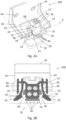
- Fig. 1A shows a perspective view of an assembly 100 and Fig. 1B shows a cross-sectional top view of the assembly 100 comprising an electric connector 10 and a bracket 26, according to an embodiment of the present disclosure.
- the connector 10 comprises a plurality of cavities 12, a terminal lock 14, and a control element 16.
- the cavities 12 are located on a top side of the electric connector 10 and the cavities 12 extend from the top side of the electric connector 10 in a direction towards a lower side of the electric connector 10.
- the cavities 12 are configured to receive electric terminals (not shown).
- Each cavity 12 may accommodate at least one electric terminal, but it may also possible that a cavity 12 remains empty, i.e. the cavity 12 may not accommodate an electric terminal.
- Each of the electric terminals is secured in its respective cavity 12 by means of the terminal lock 14.
- the terminal lock 14 is moveable between an unlocked position ( Fig. 1 ) and a locked position ( Figs. 2 and 3 ), wherein the electric terminals are locked in the cavities 12 when the terminal lock 14 is in the locked position.
- the electric terminals are not locked in the cavities 12 when the terminal lock 14 is in the unlocked position.
- the terminal lock 14 is movably mounted on the electric connector 10 and the terminal lock 14 is U-shaped to encompass a housing 36 of the plurality of cavities 12.
- the terminal lock 14 is hold on the electric connector 10 by means of at least one spring hook 34, preferably by means of two spring hooks 34. Each of the two spring hooks 34 is located at the top of an (parallel) edge formed by the U-shape of the terminal lock 14.
- the spring hooks 34 hook behind a protrusion 38 of the housing 36 and thereby lock the terminal lock 14 in the locked position.
- the terminal lock 14 In the unlocked position of the terminal lock 14, the terminal lock 14 is prevented to detach from the electric connector 10 by holding the terminal lock 14 by means of the spring hook 34 at an edge 42 of the housing 36.
- the terminal lock 14 is located above guide rails 40 that may facilitate the movement of the terminal lock 14 from the unlocked position into the locked position and vice versa.
- the terminal lock 14 further comprises a recess 20 adapted to partly accommodate the control element 16 when the terminal lock 14 is in the locked position, and a blocking element 22 adapted to block an entry of the control element 16 into the recess 20 when the terminal lock 14 is in the unlocked position.
- the terminal lock 14 may comprise a plurality of blocking elements 22 and a plurality of recesses 20, for example two blocking elements 22 and two recesses 20.
- the two blocking elements 22 and the two recesses 20 may be located at opposite sides of the terminal lock 14 as shown in Fig. 1B .
- the blocking element 22 moves from a blocking position into a non-blocking position if the terminal lock 14 is moved from the unlocked position into the locked position.
- the recess 20 moves in the same direction as the blocking element 22 when the terminal lock 14 is moved from the unlocked position into the locked position.
- the control element 16 is able to detect the unlocked position and the locked position of the terminal lock 14. If the control element 16 of the electric connector 10 is not movable into the recess 20, i.e. if the control element 16 of the electric connector 10 is blocked by means of the blocking element 22, the unlocked position of the terminal lock 14 is detected as shown in Fig. 1A and Fig. 1 B . If the terminal lock 14 is in the unlocked position the control element 16 is blocked by means of the blocking element 22 of the terminal lock 14.
- the blocking element 22 blocks the control element 16 from entering the recess 20 of the terminal lock 14 and the control element 16 is moveable only until the control element 16 contacts the blocking element 22.
- the control element 16 prevents to fully insert the electric control 10 into the opening of the bracket 26.
- Fig. 2A shows a perspective view of the assembly 100 of Fig. 1
- Fig. 2B shows a cross-sectional top view of the assembly 100 not fully inserted into an opening of the bracket 26 with a locked terminal lock 14.
- the locked position of the terminal lock 14 is detected by means of the control element 16 when the control element 16 of the electric connector 10 is movable into the recess 20 of the terminal lock 14 as shown in Fig. 2A or Fig. 2B .
- the control element 16 can partly be accommodated in the recess 20. If the control element 16 of the electric connector 10 is movable into the recess 20, i.e. if the control element 16 of the electric connector 10 is not blocked by means of the blocking element 22, the locked position of the terminal lock 14 is detected.
- the electric connector 10 further comprises at least one spring lever 28, wherein the at least one spring lever 28 comprises the control element 16.
- the control element 16 is designed as a hook 32 according to the described embodiment but is not limited to that shape.
- the spring lever 28 is movable around an attachment point at the electric connector 10 such that the hook 32 is moveable into the recess 20 of the terminal lock 14 when the terminal lock 14 is in the locked position.
- the electric connector 10 may comprise a plurality of spring levers 28, in particular two spring levers 28.
- the two spring levers 28 are located on the electric connector 10 at two sides of the terminal lock 14 as shown in Fig. 2B , for example.
- the terminal lock 14 of this embodiment comprises two recesses 20 and two blocking elements 22.
- the two spring levers 28 of this embodiment, in particular each of the respective hooks 32 of the spring levers 28 are blocked by means of the respective blocking element 22 if the terminal lock is in the unlocked position (as shown in Fig. 1B ).
- the bracket 26 comprises a U-shaped opening adapted to receive the electric connector 10.
- the bracket 26 may be a steel bracket 26 or a plastic bracket 26, wherein the bracket 26 may be part of any component in a vehicle.
- the described bracket 26 is a slide-in bracket 26, wherein the bracket 26 comprises a U-shaped opening to laterally insert the electric connector 10 by sliding in the electric connector 10 into the U-shaped opening of the bracket 26.
- the bracket 26 may comprise mounting holes 44 to attach the bracket 26 to a vehicle.
- the electric connector 10 further comprises two parallel slots 18.
- the two parallel slots 18 receive two parallel edges 24 of the U-shaped opening when the electric connector 10 is inserted into the opening of the bracket 26.
- the control element 16, in particular the hook 32 of the spring lever 28 is configured to be moved when the electric connector 10 is laterally inserted into the opening of the bracket 26. As can be seen in Figs. 1A to Fig. 2B , the edges 24 contact the control element 16 if the electric connector 10 is inserted into the opening of the bracket 26.
- Fig. 3A shows a perspective view of the assembly
- Fig. 3B shows a cross-sectional top view of the assembly fully inserted into the opening of the bracket with a locked terminal lock.
- the control element 16 moves in a direction to the terminal lock 14 if the electric connector 10 is further inserted into the opening of the bracket 26, i.e. the control element 16 is pushed by means of the edges 24.
- the terminal lock 14 is in the locked position the control element 16 moves into the recess 20 of the terminal lock 14.
- the bracket 26 further comprises a notch 30 for locking the electric connector 10 in the opening of the bracket when the electric connector if fully inserted into the bracket 26.
- the control element 16 reaches the notch of the bracket 26 when the electric connector 10 is further inserted into the opening of the bracket 26.
- the control element 16 moves from the recess 20 of the terminal lock 14 into the notch 30 of the bracket 26 since the control element 16 is biased.
- the notch 30 partly accommodates the control element 16, in particular the hook 32 of the spring lever 28, when the electric connector 10 is fully inserted into the bracket 26 and thus, the electric connector 10 is locked in the opening of the bracket 26.
- the control element 16 is removable from the notch 30 of the bracket 26 only if the control element 16 is moved back in the direction of the recess 20 again.
- the functionality of the assembly 100 may be described as follows.
- the electric connector 10 is not inserted into the opening of the bracket 26 and the terminal lock 14 is in the unlocked position.
- a plurality of electric terminals may be inserted into the cavities 12 of the electric connector 10.
- the terminal lock 14 may be moved from the unlocked position into the locked position to secure the electric terminals.
- the electric connector 10 is laterally inserted into the opening of the bracket 26. If the terminal lock 14 has been locked correctly, i.e. the spring hook 34 hooks in the protrusion 38 of the housing 36 and thereby locks the terminal lock 14 in the locked position, the control element 16 is moved partially into the recess 20 of the terminal lock 14 when the terminal lock 14 is in the locked position.
- the electric connector 10 can be fully inserted into the opening of the bracket 26.
- the electric connector 10 is locked in the notch 30 of the bracket 26 when the electric connector 10 is fully inserted into the bracket 26.
- a fully inserted electric connector 10 signalizes that the terminal lock 14 is in the locked position, thus, a state of the terminal lock 14 in the locked position has been detected. Otherwise, if the terminal lock 14 has not been locked correctly, the control element 16 is blocked by means of the blocking element 22 from entering the recess 20 of the terminal lock 14. The control element 16 prevents to fully insert the electric connector 10 into the opening of the bracket 26.
- Fig. 4 shows a flow diagram 200 illustrating a method for detecting the state of the terminal lock 14 of the assembly 100.
- the electric connector 10 is inserted into the opening of the bracket 26.
- the locked position of the terminal lock 14 may be detected at step 204 by means of the control element 16. Otherwise, when the electric connector 10 is blocked from being laterally fully inserted into the opening of the bracket 26, the unlocked position of the terminal lock 14 detected at step 206 by means of the control element 16.
- the method may further include: moving the terminal lock 14 into the locked position fully inserting the electric connector 10 into the opening of the bracket 26.
Landscapes
- Details Of Connecting Devices For Male And Female Coupling (AREA)
Abstract
An electric connector includes a plurality of cavities, wherein each cavity is designed to receive an electric terminal, a terminal lock mounted on the electric connector and adapted to lock each electric terminal in its cavity, wherein the terminal lock is moveable between an unlocked position and a locked position, and a control element moveable to detect the unlocked position and the locked position of the terminal lock.
Description
- The present disclosure relates to an electric connector, an assembly comprising the electric connector and a bracket, and a method for detecting a state of a terminal lock.
- To secure electric terminals in an electric connector, a terminal lock or secondary lock may be provided on the electric connector. Electric connectors adapted to receive electric terminals may be used for example in vehicles, wherein safety aspects and product reliability require that a secondary lock is in a locked position to ensure that the electric terminals are locked in the electric connector.
- Accordingly, there is a demand to reliably recognize that a lock which secures electric terminals in an electric connector is in a locked position.
- This demand is satisfied by an electric connector, an assembly and a method according to the independent claims.
- The present disclosure provides an electric connector, an assembly, and a method according to the independent claims. Embodiments are given in the subclaims, the description and the drawings.
- In one aspect, the present disclosure may be directed at an electric connector, wherein the electric connector comprises a plurality of cavities, wherein each cavity is designed to receive an electric terminal, a terminal lock mounted on the electric connector and adapted to lock each electric terminal in its cavity, wherein the terminal lock is moveable between an unlocked position and a locked position, and a control element moveable to detect the unlocked position and the locked position of the terminal lock.
- The electric connector may be a male or a female connector for coupling a cable. For example, the electric connector may be used in a vehicle like a car or a truck to connect power cables or data cables. The cable may be connected to the electric connector by means of electric terminals. The electric connector comprises a plurality of cavities to receive a plurality of electric terminals.
- The terminal lock may be configured to fix or secure each electric terminal in its cavity. For this purpose, the terminal lock may be moved from the unlocked position into the locked position, wherein it is not be possible to remove the electric terminals out of the cavities or to insert the electric terminals into the cavities in the locked position. On the other hand, if the terminal lock is in the unlocked position, it is possible to insert the electric terminals into the cavities or to remove the electric terminals from the cavities of the electric connector.
- The control element is adapted to detect an unlocked terminal lock, i.e. by means of the control element it is possible to detect the unlocked position of the electric connector. Thus, error indications or malfunctions may be avoided. Since the control element is part of the electric connector, there is no need of an additional, separate device to detect an unlocked terminal lock.
- According to an embodiment, the terminal lock may comprise a recess adapted to partly accommodate the control element when the terminal lock is in the locked position, and a blocking element adapted to block an entry of the control element into the recess when the terminal lock is in the unlocked position.
- The terminal lock may comprise several components, wherein each of the components may have different functionalities. The recess of the terminal lock, for example, may enable to detect the locked position of the terminal lock by means of the control element in that the recess partly accommodates the control element when the terminal lock is in the locked position. The recess may be located at a lower edge of the terminal lock, preferably in an area of an outer edge of the terminal lock.
- The blocking element may enable to detect the unlocked position of the terminal lock in that the blocking element disables that the control element enters into the recess of the terminal lock when the terminal lock is in the unlocked position. The blocking element may be located next to the recess at a lower edge of the terminal lock. The terminal lock may comprise a plurality of blocking elements and a plurality of recesses, for example two blocking elements and two recesses.
- According to an embodiment, the electric connector may comprise at least one spring lever comprising the control element. The electric connector may comprise a plurality of spring levers, for example two spring levers, wherein each spring lever comprises a respective control element. The at least one spring lever may be located at the electric connector such that the spring lever and the control element of each respective spring lever are moved in a direction towards the terminal lock. The at least one spring lever may be moved manually, e.g. a user may press the at least one spring lever in the direction towards the terminal lock, or the at least one spring lever may be moved automatically, e.g. by a robot. Also, the at least one spring lever may be moved by an object, for example if the spring lever is sliding alongside an object, wherein the at least one spring lever contacts the object. The object may be a stationary object, e.g. an edge of a bracket. The different kind of movement possibilities of the at least one spring lever may lead to a plurality of opportunities to detect an unlocked terminal lock and a locked terminal lock, by means of the at least one spring lever, in particular by means of the respective control element of each spring lever.
- According to an embodiment, the spring lever may comprise a hook. The hook may be located at one end of the spring lever. The hook may be designed to be partly accommodated in the recess of the terminal lock when the spring lever moves in the direction towards the terminal lock and the terminal lock is in the locked position. Thus, the hook may form the control element as described herein.
- According to an embodiment, the terminal lock may be U-shaped and may be adapted to encompass a housing of the plurality of cavities. The terminal lock may be movable transverse to an insertion direction of the electric terminals into the housing of the electric terminals. For example two parallel sides of the U-shaped terminal lock may be adapted to slide alongside the housing of the cavities when the terminal lock is moved from the unlocked position into the locked position, or vice versa. Thus, a catching of the terminal lock may be avoided.
- According to an embodiment, the terminal lock may comprise a spring hook adapted to lock the terminal lock in the locked position. The terminal lock may comprise a plurality of spring hooks, for example two spring hooks, wherein each spring hook may be located at an open end of the two parallel sides of the U-shaped terminal lock. The spring hook may comprise a protrusion at one end of the spring hook. To lock the terminal lock in the locked position, the protrusion of the at least one spring hook may engage behind a protrusion of the electric connector. The protrusion of the electric connector may be located at the housing of the cavities.
- In another aspect, the present disclosure is directed at an assembly, wherein the assembly comprises an electric connector as described above and a bracket, wherein the bracket comprises a U-shaped opening adapted to receive the electric connector.
- The bracket may be any suitable device or an interface that is able to receive the electric connector as described herein. The bracket may be mounted on a vehicle or be part of any component in the vehicle. The bracket may be a steel bracket or a plastic bracket or out of any other suitable material that is able to hold the electric connector. Furthermore, the bracket may be designed as a slide-in bracket instead of a pass-through bracket, i.e. the electric connector may be laterally inserted into the bracket by sliding the electric connector into the U-shaped opening of the bracket, i.e. one side of the bracket is open. On the contrary, a pass-through bracket may not have an open side but a hole inside the pass-through bracket, wherein an electric connector may be inserted into the pass-through bracket by pushing the electric connector through the hole of the pass-through bracket. The advantage of the slide-in assembly as described herein is that compared to a pass-through system, no additional space from below of the bracket is needed for inserting the electric connector into the bracket. Also, less harness and less slack are required by the slide-in assembly compared to a pass-through system.
- According to an embodiment, the electric connector of the assembly may further comprise two parallel slots adapted to receive two parallel edges of the opening. The U-shaped opening of the bracket may shape two parallel edges and a third edge perpendicular to each of the two parallel edges. Equivalent to the two parallel edges of the opening of the bracket, the electric connector may comprise two parallel slots, wherein the two parallel edges of the opening of the bracket may fit into the two parallel slots of the electric connector when the electric connector is inserted into the opening of the bracket. Additionally, the electric connector may comprise a third slot that is perpendicular to the two parallel slots, wherein the third edge of the opening of the bracket may fit in the third slot of the electric connector when the electric connector is fully inserted into the opening of the bracket. The slots may be dimensioned that there is a minimum of clearance between the edges and the slots, wherein the minimum of clearance allows to insert the electric connector into the opening of the bracket. Thus, if the electric connector is fully inserted into the opening of the bracket, the electric connector is hold steady by means of the bracket.
- According to an embodiment, the control element of the electric connector may be adapted to be moved when the electric connector is laterally inserted into the opening of the bracket. The control element may be moved by means of the edges of the opening of the bracket. The two parallel edges of the U-shaped opening of the bracket may contact the control element if the electric connector is laterally inserted into the opening of the bracket. The two parallel edges of the opening may slide in the two parallel slots of the electric connector until the two parallel edges contact the control element.
- According to an embodiment, the control element of the electric connector may be adapted to be moved into a recess of the terminal lock when the electric connector is laterally inserted into the opening of the bracket and when the terminal lock is in the locked position. As described above, the two parallel edges of the U-shaped opening of the bracket may move the control element if the electric connector is laterally inserted into the opening of the bracket. The control element is moved into the recess of the terminal lock when the electric connector is further inserted into the opening of the bracket after the two parallel edges of the opening abut against the control element.
- According to an embodiment, the bracket may comprise a notch for locking the electric connector in the opening of the bracket when the electric connector is fully inserted into the bracket. The electric connector may be fully inserted into the bracket if the two parallel slots of the electric connector are inserted completely into the two parallel edges of the opening of the bracket. The notch may be adapted to partly accommodate the control element, in particular the hook of the spring lever, when the electric connector is fully inserted into the bracket. The electric connector may be fully insertable into the bracket only if the terminal lock is in the locked position. If the terminal lock is in the locked position and the electric connector is inserted into the opening of the bracket, the control element moves partly into the recess of the terminal lock which enables to insert the electric connector further into the opening of the bracket. The control element may be biased when the control element is partly accommodated in the recess of the terminal lock. The control element may reach the notch of the bracket when the electric connector is further inserted into the opening of the bracket. The control element may move from the recess of the terminal lock into the notch of the bracket due the bias of the control element. The control element may be removed from the notch of the bracket only if the control element is moved back in the direction of the recess again. Thus, the electric connector is safely fixed in the bracket if the electric connector is fully inserted into the bracket.
- According to an embodiment, the assembly may further comprise a blocking element configured to block the control element of the electric connector from entering a recess of the terminal lock when the electric connector is laterally inserted into the opening of the bracket and when the terminal lock is in the unlocked position. As described above, the two parallel edges of the U-shaped opening of the bracket may contact the control element if the electric connector is laterally inserted into the opening of the bracket. The control element is moved into the direction of the terminal lock when the electric connector is further inserted into the opening of the bracket after the two parallel edges of the opening abut against a respective control element. Due to the blocking element, the control element cannot be moved into the recess of the terminal lock. Instead, the control element can only be moved until the control element contacts the blocking element. Thus, the electric connector cannot be fully inserted into the bracket if the terminal lock is in the unlocked position.
- According to an embodiment, the control element may prevent to fully insert the electric connector into the opening of the bracket when the electric connector is laterally inserted into the opening of the bracket and when the terminal lock is in the unlocked position.
- The electric connector may not be fully insertable into the bracket if the terminal lock is in the unlocked position. If the terminal lock is in the unlocked position and the electric connector is inserted into the opening of the bracket, the control element is blocked by means of the blocking element of the terminal lock from entering the recess of the terminal lock. Thus, the control element stays in its position, i.e. the control element is not moveable into the recess and the electric connector cannot be further inserted into the opening of the bracket, in particular the electric connector cannot be fully inserted into the bracket. The two parallel edges of the U-shaped opening of the bracket may not slide further in the two parallel slots of the electric connector since the two parallel slots are blocked by the control element. An unlocked terminal lock, i.e. the terminal lock is in the unlocked position, may be detected if the electric connector cannot be fully inserted into the opening of the bracket. The detection of an unlocked terminal lock may be tactile without visual control of the terminal lock.
- In another aspect, the present disclosure is directed at a method for detecting a state of a terminal lock of an assembly as described above, wherein the method comprises the following steps: inserting the electric connector into the opening of the bracket, and detecting by means of the control element the locked position of the terminal lock when the electric connector is laterally fully inserted into the opening of the bracket, or detecting by means of the control element the unlocked position of the terminal lock when the electric connector is blocked from being laterally fully inserted into the opening of the bracket.
- According to an embodiment, the method may further comprise the following steps: moving the terminal lock into the locked position, and fully inserting the electric connector into the opening of the bracket
- The detection of an unlocked terminal lock, i.e. the terminal lock is in the unlocked position, or a locked terminal, i.e. the terminal lock is in the locked position, may be done at a vehicle plant.
- Exemplary embodiments and functions of the present disclosure are described herein in conjunction with the following drawings, showing schematically:
- Fig. 1A
- a perspective view of an assembly with an unlocked terminal lock, comprising an electric connector and a bracket according to an embodiment of the present disclosure;
- Fig. 1B
- a cross-sectional top view of the assembly with an unlocked terminal lock;
- Fig. 2A
- a perspective view of the assembly not fully inserted into an opening of the bracket with a locked terminal lock;
- Fig. 2B
- a cross-sectional top view of the assembly not fully inserted into the opening of the bracket with a locked terminal lock;
- Fig. 3A
- a perspective view of the assembly fully inserted into the opening of the bracket with a locked terminal lock;
- Fig. 3B
- a cross-sectional top view of the assembly fully inserted into the opening of the bracket with a locked terminal lock; and
- Fig. 4
- a flow diagram illustrating a method for detecting the state of the terminal lock of the assembly.
-
Fig. 1A shows a perspective view of anassembly 100 andFig. 1B shows a cross-sectional top view of theassembly 100 comprising anelectric connector 10 and abracket 26, according to an embodiment of the present disclosure. Theconnector 10 comprises a plurality ofcavities 12, aterminal lock 14, and acontrol element 16. - The
cavities 12 are located on a top side of theelectric connector 10 and thecavities 12 extend from the top side of theelectric connector 10 in a direction towards a lower side of theelectric connector 10. Thecavities 12 are configured to receive electric terminals (not shown). Eachcavity 12 may accommodate at least one electric terminal, but it may also possible that acavity 12 remains empty, i.e. thecavity 12 may not accommodate an electric terminal. Each of the electric terminals is secured in itsrespective cavity 12 by means of theterminal lock 14. - The
terminal lock 14 is moveable between an unlocked position (Fig. 1 ) and a locked position (Figs. 2 and3 ), wherein the electric terminals are locked in thecavities 12 when theterminal lock 14 is in the locked position. The electric terminals are not locked in thecavities 12 when theterminal lock 14 is in the unlocked position. Theterminal lock 14 is movably mounted on theelectric connector 10 and theterminal lock 14 is U-shaped to encompass ahousing 36 of the plurality ofcavities 12. Theterminal lock 14 is hold on theelectric connector 10 by means of at least onespring hook 34, preferably by means of two spring hooks 34. Each of the two spring hooks 34 is located at the top of an (parallel) edge formed by the U-shape of theterminal lock 14. In the locked position of theterminal lock 14, the spring hooks 34 hook behind aprotrusion 38 of thehousing 36 and thereby lock theterminal lock 14 in the locked position. In the unlocked position of theterminal lock 14, theterminal lock 14 is prevented to detach from theelectric connector 10 by holding theterminal lock 14 by means of thespring hook 34 at anedge 42 of thehousing 36. Furthermore, theterminal lock 14 is located aboveguide rails 40 that may facilitate the movement of theterminal lock 14 from the unlocked position into the locked position and vice versa. - The
terminal lock 14 further comprises arecess 20 adapted to partly accommodate thecontrol element 16 when theterminal lock 14 is in the locked position, and a blockingelement 22 adapted to block an entry of thecontrol element 16 into therecess 20 when theterminal lock 14 is in the unlocked position. Theterminal lock 14 may comprise a plurality of blockingelements 22 and a plurality ofrecesses 20, for example two blockingelements 22 and tworecesses 20. The two blockingelements 22 and the tworecesses 20 may be located at opposite sides of theterminal lock 14 as shown inFig. 1B . The blockingelement 22 moves from a blocking position into a non-blocking position if theterminal lock 14 is moved from the unlocked position into the locked position. Simultaneously, therecess 20 moves in the same direction as the blockingelement 22 when theterminal lock 14 is moved from the unlocked position into the locked position. Thecontrol element 16 is able to detect the unlocked position and the locked position of theterminal lock 14. If thecontrol element 16 of theelectric connector 10 is not movable into therecess 20, i.e. if thecontrol element 16 of theelectric connector 10 is blocked by means of the blockingelement 22, the unlocked position of theterminal lock 14 is detected as shown inFig. 1A and Fig. 1 B . If theterminal lock 14 is in the unlocked position thecontrol element 16 is blocked by means of the blockingelement 22 of theterminal lock 14. Thus, the blockingelement 22 blocks thecontrol element 16 from entering therecess 20 of theterminal lock 14 and thecontrol element 16 is moveable only until thecontrol element 16 contacts the blockingelement 22. Thecontrol element 16 prevents to fully insert theelectric control 10 into the opening of thebracket 26. -
Fig. 2A shows a perspective view of theassembly 100 ofFig. 1 , andFig. 2B shows a cross-sectional top view of theassembly 100 not fully inserted into an opening of thebracket 26 with a lockedterminal lock 14. The locked position of theterminal lock 14 is detected by means of thecontrol element 16 when thecontrol element 16 of theelectric connector 10 is movable into therecess 20 of theterminal lock 14 as shown inFig. 2A or Fig. 2B . In the locked position of theterminal lock 14, thecontrol element 16 can partly be accommodated in therecess 20. If thecontrol element 16 of theelectric connector 10 is movable into therecess 20, i.e. if thecontrol element 16 of theelectric connector 10 is not blocked by means of the blockingelement 22, the locked position of theterminal lock 14 is detected. - The
electric connector 10 further comprises at least onespring lever 28, wherein the at least onespring lever 28 comprises thecontrol element 16. Thecontrol element 16 is designed as ahook 32 according to the described embodiment but is not limited to that shape. Thespring lever 28 is movable around an attachment point at theelectric connector 10 such that thehook 32 is moveable into therecess 20 of theterminal lock 14 when theterminal lock 14 is in the locked position. Theelectric connector 10 may comprise a plurality of spring levers 28, in particular two spring levers 28. The twospring levers 28 are located on theelectric connector 10 at two sides of theterminal lock 14 as shown inFig. 2B , for example. As described above, theterminal lock 14 of this embodiment comprises tworecesses 20 and two blockingelements 22. The twospring levers 28 of this embodiment, in particular each of therespective hooks 32 of the spring levers 28 are blocked by means of therespective blocking element 22 if the terminal lock is in the unlocked position (as shown inFig. 1B ). - The
bracket 26 comprises a U-shaped opening adapted to receive theelectric connector 10. Thebracket 26 may be asteel bracket 26 or aplastic bracket 26, wherein thebracket 26 may be part of any component in a vehicle. The describedbracket 26 is a slide-inbracket 26, wherein thebracket 26 comprises a U-shaped opening to laterally insert theelectric connector 10 by sliding in theelectric connector 10 into the U-shaped opening of thebracket 26. Thebracket 26 may comprise mountingholes 44 to attach thebracket 26 to a vehicle. In order to insert theelectric connector 10 into the opening of thebracket 26, theelectric connector 10 further comprises twoparallel slots 18. The twoparallel slots 18 receive twoparallel edges 24 of the U-shaped opening when theelectric connector 10 is inserted into the opening of thebracket 26. Thecontrol element 16, in particular thehook 32 of thespring lever 28 is configured to be moved when theelectric connector 10 is laterally inserted into the opening of thebracket 26. As can be seen inFigs. 1A to Fig. 2B , theedges 24 contact thecontrol element 16 if theelectric connector 10 is inserted into the opening of thebracket 26. -
Fig. 3A shows a perspective view of the assembly andFig. 3B shows a cross-sectional top view of the assembly fully inserted into the opening of the bracket with a locked terminal lock. Thecontrol element 16 moves in a direction to theterminal lock 14 if theelectric connector 10 is further inserted into the opening of thebracket 26, i.e. thecontrol element 16 is pushed by means of theedges 24. When theterminal lock 14 is in the locked position thecontrol element 16 moves into therecess 20 of theterminal lock 14. Thebracket 26 further comprises anotch 30 for locking theelectric connector 10 in the opening of the bracket when the electric connector if fully inserted into thebracket 26. Thecontrol element 16 reaches the notch of thebracket 26 when theelectric connector 10 is further inserted into the opening of thebracket 26. Thecontrol element 16 moves from therecess 20 of theterminal lock 14 into thenotch 30 of thebracket 26 since thecontrol element 16 is biased. Thenotch 30 partly accommodates thecontrol element 16, in particular thehook 32 of thespring lever 28, when theelectric connector 10 is fully inserted into thebracket 26 and thus, theelectric connector 10 is locked in the opening of thebracket 26. Thecontrol element 16 is removable from thenotch 30 of thebracket 26 only if thecontrol element 16 is moved back in the direction of therecess 20 again. - Summing up, the functionality of the
assembly 100 may be described as follows. In an initial state, theelectric connector 10 is not inserted into the opening of thebracket 26 and theterminal lock 14 is in the unlocked position. A plurality of electric terminals may be inserted into thecavities 12 of theelectric connector 10. Theterminal lock 14 may be moved from the unlocked position into the locked position to secure the electric terminals. Theelectric connector 10 is laterally inserted into the opening of thebracket 26. If theterminal lock 14 has been locked correctly, i.e. thespring hook 34 hooks in theprotrusion 38 of thehousing 36 and thereby locks theterminal lock 14 in the locked position, thecontrol element 16 is moved partially into therecess 20 of theterminal lock 14 when theterminal lock 14 is in the locked position. Thus, theelectric connector 10 can be fully inserted into the opening of thebracket 26. Theelectric connector 10 is locked in thenotch 30 of thebracket 26 when theelectric connector 10 is fully inserted into thebracket 26. A fully insertedelectric connector 10 signalizes that theterminal lock 14 is in the locked position, thus, a state of theterminal lock 14 in the locked position has been detected. Otherwise, if theterminal lock 14 has not been locked correctly, thecontrol element 16 is blocked by means of the blockingelement 22 from entering therecess 20 of theterminal lock 14. Thecontrol element 16 prevents to fully insert theelectric connector 10 into the opening of thebracket 26. If it is not possible to fully insert theelectric connector 10 into the opening of thebracket 26 theterminal lock 14 is in the unlocked position, thus, a state of theterminal lock 14 in the unlocked position has been detected. Moving theterminal lock 14 into the locked position allows to fully insert theelectric connector 10 into the opening of thebracket 26. Thus, the problem of detecting a not closed, i.e. an unlockedterminal lock 14 before anelectric connector 10 is finally mated on abracket 26, e.g. a vehicle interface, has been solved. -
Fig. 4 shows a flow diagram 200 illustrating a method for detecting the state of theterminal lock 14 of theassembly 100. Atstep 202, theelectric connector 10 is inserted into the opening of thebracket 26. When theelectric connector 10 is laterally fully inserted into the opening of thebracket 26, the locked position of theterminal lock 14 may be detected atstep 204 by means of thecontrol element 16. Otherwise, when theelectric connector 10 is blocked from being laterally fully inserted into the opening of thebracket 26, the unlocked position of theterminal lock 14 detected atstep 206 by means of thecontrol element 16. - According to an embodiment, the method may further include: moving the
terminal lock 14 into the locked position fully inserting theelectric connector 10 into the opening of thebracket 26. -
- 10
- electric connector
- 12
- cavity
- 14
- terminal lock
- 16
- control element
- 18
- slot
- 20
- recess
- 22
- blocking element
- 24
- edge
- 26
- bracket
- 28
- spring lever
- 30
- notch
- 32
- hook
- 34
- spring hook
- 36
- housing
- 38
- protrusion
- 40
- guide rail
- 42
- edge
- 44
- mounting holes
- 100
- assembly
- 200
- flow diagram illustrating a method for detecting the state of the terminal lock of the assembly
- 202
- step of inserting an electric connector into an opening of a bracket
- 204
- step of detecting a locked position of the terminal lock
- 206
- step of detecting an unlocked position of the terminal lock
- A
- section plane
Claims (15)
- An electric connector (10), comprising:a plurality of cavities (12), wherein each cavity (12) is designed to receive an electric terminal;a terminal lock (14) mounted on the electric connector (10) and adapted to lock each electric terminal in its cavity (12), wherein the terminal lock (14) is moveable between an unlocked position and a locked position; anda control element (16) moveable to detect the unlocked position and the locked position of the terminal lock (14).
- The electric connector (10) according to claim 1,
wherein the terminal lock (14) comprises:a recess (20) adapted to partly accommodate the control element (16) when the terminal lock (14) is in the locked position; anda blocking element (22) adapted to block an entry of the control element (16) into the recess (20) when the terminal lock (14) is in the unlocked position. - The electric connector (10) according to claim 1 or 2,
wherein the electric connector (16) comprises:
at least one spring lever (32) comprising the control element (16). - The electric connector (10) according to claim 3,
wherein the spring lever (32) comprises a hook. - The electric connector (10) according to any one of claims 1 to 4,
wherein the terminal lock (14) is U-shaped and adapted to encompass a housing (36) of the plurality of cavities (12). - The electric connector (10) according to any one of claims 1 to 5,
wherein the terminal lock (14) comprises a spring hook (34) adapted to lock the terminal lock (14) in the locked position. - An assembly (100), comprising:an electric connector (10) according to any one of claims 1 to 6; anda bracket (26) comprising a U-shaped opening adapted to receive the electric connector (10).
- The assembly (100) according to claim 7,
wherein the electric connector (10) further comprises two parallel slots (18) adapted to receive two parallel edges (28) of the opening. - The assembly (100) according to claim 7 or 8,
wherein the control element (16) of the electric connector (10) is adapted to be moved when the electric connector (10) is laterally inserted into the opening of the bracket (26). - The assembly (100) according to any one of claims 7 to 9,
wherein the control element (16) of the electric connector (10) is adapted to be moved into a recess (20) of the terminal lock (14) when the electric connector (10) is laterally inserted into the opening of the bracket (26) and when the terminal lock (14) is in the locked position. - The assembly (100) according to any one of claims 7 to 10,
wherein the bracket (26) comprises a notch (30) for locking the electric connector (10) in the opening of the bracket (26) when the electric connector (10) is fully inserted into the bracket (26). - The assembly (100) according to any one of claims 7 to 11,
further comprising a blocking element (22) configured to block the control element (16) of the electric connector (10) from entering a recess (20) of the terminal lock (14) when the electric connector (10) is laterally inserted into the opening of the bracket (26) and when the terminal lock (14) is in the unlocked position. - The assembly (100) according to any one of claims 7 to 12,
wherein the control element (16) prevents to fully insert the electric connector (10) into the opening of the bracket (26) when the electric connector (10) is laterally inserted into the opening of the bracket (26) and when the terminal lock (14) is in the unlocked position. - A method for detecting a state of a terminal lock (14) of an assembly (100) according to any one of claims 7 to 13, comprising:inserting the electric connector (10) into the opening of the bracket (26); anddetecting by means of the control element (16) the locked position of the terminal lock (14) when the electric connector (10) is laterally fully inserted into the opening of the bracket (26); ordetecting by means of the control element (16) the unlocked position of the terminal lock (14) when the electric connector (10) is blocked from being laterally fully inserted into the opening of the bracket (26).
- The method according to claim 14, further comprising:moving the terminal lock (14) into the locked position; andfully inserting the electric connector (10) into the opening of the bracket (26).
Priority Applications (1)
| Application Number | Priority Date | Filing Date | Title |
|---|---|---|---|
| EP21206722.7A EP4178041A1 (en) | 2021-11-05 | 2021-11-05 | An electric connector, an assembly and a method for detecting a state of a terminal lock |
Applications Claiming Priority (1)
| Application Number | Priority Date | Filing Date | Title |
|---|---|---|---|
| EP21206722.7A EP4178041A1 (en) | 2021-11-05 | 2021-11-05 | An electric connector, an assembly and a method for detecting a state of a terminal lock |
Publications (1)
| Publication Number | Publication Date |
|---|---|
| EP4178041A1 true EP4178041A1 (en) | 2023-05-10 |
Family
ID=78536047
Family Applications (1)
| Application Number | Title | Priority Date | Filing Date |
|---|---|---|---|
| EP21206722.7A Withdrawn EP4178041A1 (en) | 2021-11-05 | 2021-11-05 | An electric connector, an assembly and a method for detecting a state of a terminal lock |
Country Status (1)
| Country | Link |
|---|---|
| EP (1) | EP4178041A1 (en) |
Citations (5)
| Publication number | Priority date | Publication date | Assignee | Title |
|---|---|---|---|---|
| JPH02183978A (en) * | 1989-01-10 | 1990-07-18 | Nippon Ee M P Kk | Electric connector |
| JPH09320672A (en) * | 1996-05-29 | 1997-12-12 | Yazaki Corp | connector |
| JP2005044586A (en) * | 2003-07-25 | 2005-02-17 | Jst Mfg Co Ltd | Plug for electrical connection |
| US20180316132A1 (en) * | 2017-05-01 | 2018-11-01 | J.S.T. Corporation | Connector position assurance device, connector system and method for operating the connector system |
| US20200153144A1 (en) * | 2018-11-12 | 2020-05-14 | Raydiall | Connector housing equipped with an improved cable terminal position assurance (tpa) device |
-
2021
- 2021-11-05 EP EP21206722.7A patent/EP4178041A1/en not_active Withdrawn
Patent Citations (5)
| Publication number | Priority date | Publication date | Assignee | Title |
|---|---|---|---|---|
| JPH02183978A (en) * | 1989-01-10 | 1990-07-18 | Nippon Ee M P Kk | Electric connector |
| JPH09320672A (en) * | 1996-05-29 | 1997-12-12 | Yazaki Corp | connector |
| JP2005044586A (en) * | 2003-07-25 | 2005-02-17 | Jst Mfg Co Ltd | Plug for electrical connection |
| US20180316132A1 (en) * | 2017-05-01 | 2018-11-01 | J.S.T. Corporation | Connector position assurance device, connector system and method for operating the connector system |
| US20200153144A1 (en) * | 2018-11-12 | 2020-05-14 | Raydiall | Connector housing equipped with an improved cable terminal position assurance (tpa) device |
Similar Documents
| Publication | Publication Date | Title |
|---|---|---|
| EP3811469B1 (en) | Electrical connector with terminal position assurance device | |
| US6276957B1 (en) | Connector | |
| US6840789B2 (en) | Connector and a method of assembling it | |
| KR101000152B1 (en) | Electrical connector | |
| EP2966735B1 (en) | Connector assembly with dual secondary lock | |
| US5618201A (en) | Connector having engagement detecting device | |
| US20190173220A1 (en) | Electrical connector with terminal position assurance member | |
| US9409536B2 (en) | Connector assembly with automatic secondary lock | |
| EP1928061A2 (en) | A connector | |
| KR20180117548A (en) | Electrical connector with lever | |
| CN109698436B (en) | Electric connector with auxiliary handle | |
| EP3396790A1 (en) | Connector assembly for safety systems | |
| CN105703125A (en) | Electrical connector | |
| EP1094559B1 (en) | Electrical connector having a terminal retainer | |
| EP1677392A1 (en) | A divided connector and method of assembling it | |
| EP1796223A1 (en) | A connector device and a method of assembling it | |
| EP1801925B1 (en) | A connector | |
| JP3555591B2 (en) | connector | |
| US11482811B2 (en) | Lever-type connector | |
| JP3960259B2 (en) | Connector connection structure | |
| JP4544065B2 (en) | connector | |
| US6220886B1 (en) | Connector | |
| EP3665747B1 (en) | Connector housing for an electrical connector | |
| US12261395B2 (en) | Electrical connector system with miniaturized connector position assurance member | |
| JPH09270281A (en) | Connector connection detection device |
Legal Events
| Date | Code | Title | Description |
|---|---|---|---|
| PUAI | Public reference made under article 153(3) epc to a published international application that has entered the european phase |
Free format text: ORIGINAL CODE: 0009012 |
|
| STAA | Information on the status of an ep patent application or granted ep patent |
Free format text: STATUS: THE APPLICATION HAS BEEN PUBLISHED |
|
| AK | Designated contracting states |
Kind code of ref document: A1 Designated state(s): AL AT BE BG CH CY CZ DE DK EE ES FI FR GB GR HR HU IE IS IT LI LT LU LV MC MK MT NL NO PL PT RO RS SE SI SK SM TR |
|
| STAA | Information on the status of an ep patent application or granted ep patent |
Free format text: STATUS: THE APPLICATION IS DEEMED TO BE WITHDRAWN |
|
| 18D | Application deemed to be withdrawn |
Effective date: 20231111 |