EP4178011A1 - Secondary battery - Google Patents
Secondary battery Download PDFInfo
- Publication number
- EP4178011A1 EP4178011A1 EP22204892.8A EP22204892A EP4178011A1 EP 4178011 A1 EP4178011 A1 EP 4178011A1 EP 22204892 A EP22204892 A EP 22204892A EP 4178011 A1 EP4178011 A1 EP 4178011A1
- Authority
- EP
- European Patent Office
- Prior art keywords
- secondary battery
- plate
- terminal
- cap plate
- vent hole
- Prior art date
- Legal status (The legal status is an assumption and is not a legal conclusion. Google has not performed a legal analysis and makes no representation as to the accuracy of the status listed.)
- Pending
Links
Images


Classifications
-
- H—ELECTRICITY
- H01—ELECTRIC ELEMENTS
- H01M—PROCESSES OR MEANS, e.g. BATTERIES, FOR THE DIRECT CONVERSION OF CHEMICAL ENERGY INTO ELECTRICAL ENERGY
- H01M50/00—Constructional details or processes of manufacture of the non-active parts of electrochemical cells other than fuel cells, e.g. hybrid cells
- H01M50/50—Current conducting connections for cells or batteries
- H01M50/572—Means for preventing undesired use or discharge
- H01M50/584—Means for preventing undesired use or discharge for preventing incorrect connections inside or outside the batteries
- H01M50/59—Means for preventing undesired use or discharge for preventing incorrect connections inside or outside the batteries characterised by the protection means
- H01M50/593—Spacers; Insulating plates
-
- H—ELECTRICITY
- H01—ELECTRIC ELEMENTS
- H01M—PROCESSES OR MEANS, e.g. BATTERIES, FOR THE DIRECT CONVERSION OF CHEMICAL ENERGY INTO ELECTRICAL ENERGY
- H01M50/00—Constructional details or processes of manufacture of the non-active parts of electrochemical cells other than fuel cells, e.g. hybrid cells
- H01M50/10—Primary casings; Jackets or wrappings
- H01M50/147—Lids or covers
- H01M50/155—Lids or covers characterised by the material
- H01M50/16—Organic material
-
- H—ELECTRICITY
- H01—ELECTRIC ELEMENTS
- H01M—PROCESSES OR MEANS, e.g. BATTERIES, FOR THE DIRECT CONVERSION OF CHEMICAL ENERGY INTO ELECTRICAL ENERGY
- H01M50/00—Constructional details or processes of manufacture of the non-active parts of electrochemical cells other than fuel cells, e.g. hybrid cells
- H01M50/10—Primary casings; Jackets or wrappings
-
- H—ELECTRICITY
- H01—ELECTRIC ELEMENTS
- H01M—PROCESSES OR MEANS, e.g. BATTERIES, FOR THE DIRECT CONVERSION OF CHEMICAL ENERGY INTO ELECTRICAL ENERGY
- H01M10/00—Secondary cells; Manufacture thereof
- H01M10/60—Heating or cooling; Temperature control
- H01M10/61—Types of temperature control
- H01M10/613—Cooling or keeping cold
-
- H—ELECTRICITY
- H01—ELECTRIC ELEMENTS
- H01M—PROCESSES OR MEANS, e.g. BATTERIES, FOR THE DIRECT CONVERSION OF CHEMICAL ENERGY INTO ELECTRICAL ENERGY
- H01M10/00—Secondary cells; Manufacture thereof
- H01M10/60—Heating or cooling; Temperature control
- H01M10/65—Means for temperature control structurally associated with the cells
- H01M10/655—Solid structures for heat exchange or heat conduction
- H01M10/6556—Solid parts with flow channel passages or pipes for heat exchange
-
- H—ELECTRICITY
- H01—ELECTRIC ELEMENTS
- H01M—PROCESSES OR MEANS, e.g. BATTERIES, FOR THE DIRECT CONVERSION OF CHEMICAL ENERGY INTO ELECTRICAL ENERGY
- H01M10/00—Secondary cells; Manufacture thereof
- H01M10/60—Heating or cooling; Temperature control
- H01M10/65—Means for temperature control structurally associated with the cells
- H01M10/656—Means for temperature control structurally associated with the cells characterised by the type of heat-exchange fluid
- H01M10/6561—Gases
-
- H—ELECTRICITY
- H01—ELECTRIC ELEMENTS
- H01M—PROCESSES OR MEANS, e.g. BATTERIES, FOR THE DIRECT CONVERSION OF CHEMICAL ENERGY INTO ELECTRICAL ENERGY
- H01M50/00—Constructional details or processes of manufacture of the non-active parts of electrochemical cells other than fuel cells, e.g. hybrid cells
- H01M50/10—Primary casings; Jackets or wrappings
- H01M50/147—Lids or covers
- H01M50/148—Lids or covers characterised by their shape
- H01M50/15—Lids or covers characterised by their shape for prismatic or rectangular cells
-
- H—ELECTRICITY
- H01—ELECTRIC ELEMENTS
- H01M—PROCESSES OR MEANS, e.g. BATTERIES, FOR THE DIRECT CONVERSION OF CHEMICAL ENERGY INTO ELECTRICAL ENERGY
- H01M50/00—Constructional details or processes of manufacture of the non-active parts of electrochemical cells other than fuel cells, e.g. hybrid cells
- H01M50/10—Primary casings; Jackets or wrappings
- H01M50/183—Sealing members
-
- H—ELECTRICITY
- H01—ELECTRIC ELEMENTS
- H01M—PROCESSES OR MEANS, e.g. BATTERIES, FOR THE DIRECT CONVERSION OF CHEMICAL ENERGY INTO ELECTRICAL ENERGY
- H01M50/00—Constructional details or processes of manufacture of the non-active parts of electrochemical cells other than fuel cells, e.g. hybrid cells
- H01M50/30—Arrangements for facilitating escape of gases
-
- H—ELECTRICITY
- H01—ELECTRIC ELEMENTS
- H01M—PROCESSES OR MEANS, e.g. BATTERIES, FOR THE DIRECT CONVERSION OF CHEMICAL ENERGY INTO ELECTRICAL ENERGY
- H01M50/00—Constructional details or processes of manufacture of the non-active parts of electrochemical cells other than fuel cells, e.g. hybrid cells
- H01M50/30—Arrangements for facilitating escape of gases
- H01M50/342—Non-re-sealable arrangements
- H01M50/3425—Non-re-sealable arrangements in the form of rupturable membranes or weakened parts, e.g. pierced with the aid of a sharp member
-
- H—ELECTRICITY
- H01—ELECTRIC ELEMENTS
- H01M—PROCESSES OR MEANS, e.g. BATTERIES, FOR THE DIRECT CONVERSION OF CHEMICAL ENERGY INTO ELECTRICAL ENERGY
- H01M50/00—Constructional details or processes of manufacture of the non-active parts of electrochemical cells other than fuel cells, e.g. hybrid cells
- H01M50/40—Separators; Membranes; Diaphragms; Spacing elements inside cells
- H01M50/489—Separators, membranes, diaphragms or spacing elements inside the cells, characterised by their physical properties, e.g. swelling degree, hydrophilicity or shut down properties
-
- H—ELECTRICITY
- H01—ELECTRIC ELEMENTS
- H01M—PROCESSES OR MEANS, e.g. BATTERIES, FOR THE DIRECT CONVERSION OF CHEMICAL ENERGY INTO ELECTRICAL ENERGY
- H01M50/00—Constructional details or processes of manufacture of the non-active parts of electrochemical cells other than fuel cells, e.g. hybrid cells
- H01M50/50—Current conducting connections for cells or batteries
- H01M50/572—Means for preventing undesired use or discharge
- H01M50/584—Means for preventing undesired use or discharge for preventing incorrect connections inside or outside the batteries
- H01M50/586—Means for preventing undesired use or discharge for preventing incorrect connections inside or outside the batteries inside the batteries, e.g. incorrect connections of electrodes
-
- Y—GENERAL TAGGING OF NEW TECHNOLOGICAL DEVELOPMENTS; GENERAL TAGGING OF CROSS-SECTIONAL TECHNOLOGIES SPANNING OVER SEVERAL SECTIONS OF THE IPC; TECHNICAL SUBJECTS COVERED BY FORMER USPC CROSS-REFERENCE ART COLLECTIONS [XRACs] AND DIGESTS
- Y02—TECHNOLOGIES OR APPLICATIONS FOR MITIGATION OR ADAPTATION AGAINST CLIMATE CHANGE
- Y02E—REDUCTION OF GREENHOUSE GAS [GHG] EMISSIONS, RELATED TO ENERGY GENERATION, TRANSMISSION OR DISTRIBUTION
- Y02E60/00—Enabling technologies; Technologies with a potential or indirect contribution to GHG emissions mitigation
- Y02E60/10—Energy storage using batteries
Definitions
- aspects of embodiments of the present disclosure relate to a secondary battery and a battery module including the same.
- a secondary battery is a rechargeable and dischargeable battery.
- a low-capacity secondary battery comprised of one single cell packaged in the form of a pack may be used for various portable small-sized electronic devices, such as cellular phones or camcorders, and a high-capacity secondary battery in which several tens of cells are connected in a battery pack is widely used as a power source for motor drives, such as those in hybrid vehicles or electric vehicles.
- the secondary battery may be configured by incorporating into a case an electrode assembly provided by interposing a separator between a positive electrode and a negative electrode, and an electrolyte, and installing a cap plate on the case.
- a representative example of the electrode assembly may be a winding type or a stack type.
- an uncoated portion tab may protrude in a lateral or upward direction, and a current collecting member may be connected to the uncoated portion tab.
- a secondary battery is capable of efficiently discharging internal heat to the outside through a vent hole in a short time by preventing or substantially preventing a vent hole blocking phenomenon by an electrode assembly when an event, such as bottom penetration, occurs in the secondary battery.
- R1 may be 1 to 3°C ⁇ kg/W ⁇ h, which corresponds to 2,78 ⁇ 10 -4 to 8,33 ⁇ 10 -4 °C/J.
- R1 may be 0.6 to 3.5°C ⁇ kg/W ⁇ h, which corresponds to 1,67 ⁇ 10 -4 to 9,72 ⁇ 10 -4 °C/J.
- R2 may be 50 to 80°C ⁇ kg ⁇ s/W ⁇ h, which corresponds to 1,39 ⁇ 10 -2 to 2,22 ⁇ 10 -2 °C ⁇ s/J.
- R2 may be 46 to 170°C ⁇ kg ⁇ s/W ⁇ h, which corresponds to 1,28 ⁇ 10 -2 to 4,72 ⁇ 10 -2 °C ⁇ s/J.
- the insulating member may include polytetrafluoroethylene (PTFE), polyphenylene sulfide (PPS), polyphenylene (PP), or polyether ether ketone (PEEK).
- PTFE polytetrafluoroethylene
- PPS polyphenylene sulfide
- PP polyphenylene
- PEEK polyether ether ketone
- the insulating member may further include a member vent hole
- the cap plate may include a plate vent hole provided in a region corresponding to the member vent hole and a safety vent may be attached to the plate vent hole.
- the size of the member vent hole may be the same as or smaller than that of the plate vent hole.
- the insulating member may be in close contact with the cap plate and may be spaced apart from the electrode assembly.
- the member vent hole may be blocked by the safety vent.
- a battery module includes a plurality of secondary battery and an insulating sheet interposed between each pair of adjacent secondary batteries.
- first a first member, a first element, a first region, a first layer, and/or a first section discussed below could be termed a second member, a second element, a second region, a second layer, and/or a second section without departing from the teachings of the present invention.
- spatially relative terms such as “beneath,” “below,” “lower,” “above,” “upper,” and the like, may be used herein for ease of description to describe one element or feature's relationship to another element(s) or feature(s) as illustrated in the figures. It is to be understood that the spatially relative terms are intended to encompass different orientations of the device in use or operation in addition to the orientation depicted in the figures. For example, if the element or feature in the figures is turned over, elements described as “below” or “beneath” other elements or features would then be oriented “on” or “above” the other elements or features. Thus, the example term “below” can encompass both an orientation of above and below.
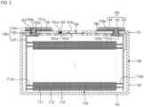
- FIGS. 1 and 2 are a perspective view and a cross-sectional view of a secondary battery according to an embodiment.
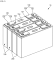
- FIG. 3 is a perspective view of a battery module in which the secondary battery of FIG. 1 is alternately disposed with an insulating sheet.
- a secondary battery 100 may include an electrode assembly 110, a first terminal 120, a second terminal 130, a case, or can, 140, a cap assembly 150, and an insulating member 160.
- the electrode assembly 110 may be provided by winding or overlapping a laminate of a first electrode plate 111, a separator 113, and a second electrode plate 112, which are in form of a thin plate or film.
- the electrode assembly 110 may have a winding axis in a horizontal direction (that is, a direction parallel or substantially parallel to a longitudinal direction of the cap assembly 150 and the insulating member 160) or may be wound in a vertical direction (that is, a direction perpendicular or substantially perpendicular to the cap assembly 150 and the insulating member 160).
- the electrode assembly 110 may be of a winding type or a stack type.
- the electrode assembly 110 may be stacked such that two or more electrode assemblies 110 have long sides adjacent to each other.
- the first electrode plate 111 of the electrode assembly 110 may function as a negative electrode, and the second electrode plate 112 may function as a positive electrode. However, the reverse is also possible.
- the first electrode plate 111 may be provided by coating a first electrode active material, such as graphite or carbon, on a first electrode current collector provided as a metal foil, such as copper, a copper alloy, nickel, or a nickel alloy, and may include a first electrode tab (or a first uncoated portion) 111a to which the first electrode active material is not applied.
- the first electrode tab 111a may be a passage for current flow between the first electrode plate 111 and the first terminal 120.
- the first electrode tab 111a may be provided by being cut to protrude from a side in advance when the first electrode plate 111 is manufactured, and may be formed integrally with the first electrode plate 111.
- a plurality of first electrode tabs 111a may be collected and welded (e.g., tack-welded), and a first current collector plate 121 of the first terminal 120 may be welded to the welded (e.g., tack-welded) first electrode tab 111a to then be coupled thereto.
- the second electrode plate 112 is provided by coating a second electrode active material, such as a transition metal oxide, on a second electrode current collector provided with a metal foil, such as aluminum or an aluminum alloy, and may include a second electrode tab (or a second uncoated portion) 112a to which the second electrode active material is not applied.
- the second electrode tab 112a may be a passage for current flow between the second electrode plate 112 and the second terminal 130.
- the second electrode tab 112a may be provided by being cut to protrude from a side in advance when the second electrode plate 112 is manufactured, and may be formed integrally with the second electrode plate 112.
- a plurality of second electrode tabs 112a may be collected and welded (e.g., tack-welded), and a second current collector plate 131 of the second terminal 130 may be welded to the welded (e.g., tack-welded) second electrode tab 112a to then be coupled thereto.
- the first electrode tab 111a may be located on a short side end of the electrode assembly 110, and the second electrode tab 112a may be located on another short side end of the electrode assembly 110.
- the separator 113 which is positioned between the first electrode plate 111 and the second electrode plate 112, may prevent or substantially prevent a short circuit and enable the movement of lithium ions, and may include polyethylene, polypropylene, or a composite film of polyethylene and polypropylene.
- the separator 113 may be replaced with an inorganic solid electrolyte, such as a sulfide-based, oxide-based, or phosphate compound-based electrolyte that does not require a liquid or gel electrolyte.
- the first terminal 120 and the second terminal 130 which are respectively electrically connected to the first electrode uncoated portion 111a of the first electrode plate 111 and the second electrode uncoated portion 112a of the second electrode plate 112, may be positioned at opposite ends of the electrode assembly 110.
- the electrode assembly 110 may be accommodated in the case 140 together with an electrolyte.
- the electrolyte may include a lithium salt, such as LiPF 6 or LiBF 4 , in an organic solvent, such as ethylene carbonate (EC), propylene carbonate (PC), diethyl carbonate (DEC), ethylmethyl carbonate (EMC), or dimethyl carbonate (DMC).
- the electrolyte may be in liquid or gel phase. In some examples, when an inorganic solid electrolyte is used, the electrolyte may be omitted.
- the first terminal 120 may be provided as a metal and may be electrically connected to the first electrode plate 111.
- the first terminal 120 may include the first current collector plate 121, a first terminal post 122, and a first terminal plate 124.
- the first current collector plate 121 may be in contact with the first electrode uncoated portion 111a protruding from an end of the electrode assembly 110.
- the first current collector plate 121 may be welded to the first electrode uncoated portion 111a.
- the first current collector plate 121 is provided in an approximately " ⁇ " shape, and a terminal hole 121a may be provided at an upper portion thereof.
- the first terminal post 122 may be inserted into the terminal hole 121a to be riveted and/or welded.
- the first current collector plate 121 may be made of copper or a copper alloy.
- the first terminal post 122 may protrude and extend by a length (e.g., a predetermined length) upward through a cap plate 151 of the cap assembly 150 and may be electrically connected to the first current collector plate 121 under the cap plate 151.
- the first terminal post 122 may protrude and extend by a length (e.g., a predetermined length) upward from the cap plate 151, and a flange 122a may be provided under the cap plate 151 to prevent or substantially prevent the first terminal post 122 from being dislodged from the cap plate 151.
- the first terminal post 122 a region positioned below the flange 122a may be inserted into the first terminal hole 121a of the first current collector plate 121 and then riveted and/or welded.
- the first terminal post 122 may be made of copper, a copper alloy, aluminum, or an aluminum alloy.
- the first terminal plate 124 may have a hole 124a, and the first terminal post 122 may be coupled to the hole 124a, and then be riveted and/or welded. In some examples, an interface between the first terminal post 122 that is exposed upward and the first terminal plate 124 may be welded to each other. For example, by providing a laser beam to boundary regions of the first terminal post 122 that is exposed upward and the first terminal plate 124, the boundary regions may be melted and then cooled and welded to each other. In some examples, the first terminal post 122 and the first terminal plate 124 may be electrically insulated from the cap plate 151.
- the second terminal 130 may also be made of a metal and may be electrically connected to the second electrode plate 112.
- the second terminal 130 may include the second current collector plate 131, a second terminal post 132, and a second terminal plate 134.
- the second current collector plate 131 may be in contact with the second electrode uncoated portion 112a protruding from an end of the electrode assembly 110.
- the second current collector plate 131 may be provided in an approximately " ⁇ " shape, and a terminal hole 131a may be provided at an upper portion thereof.
- the second terminal post 132 is fitted and coupled to the terminal hole 131a.
- the second current collector plate 131 may be made of, for example, but is not limited to, aluminum or an aluminum alloy.
- the second terminal post 132 may protrude and extend upward by a length (e.g., a predetermined length) through the cap plate 151, to be described later, and may be electrically connected to the second current collector plate 131 under the cap plate 151.
- the second terminal post 132 may protrude and extend by a length (e.g., a predetermined length) upward from the cap plate 151, and a flange 132a may be provided under the cap plate 151 to prevent or substantially prevent the second terminal post 132 from being dislodged from the cap plate 151.
- a region positioned below the flange 132a may be inserted into a second terminal hole 131a of the second current collector plate 131 and then riveted and/or welded.
- the second terminal post 132 may be made of aluminum or an aluminum alloy.
- the second terminal plate 134 may have a hole 134a.
- the second terminal plate 134 may be coupled to the second terminal post 132. That is, the second terminal post 132 may be coupled to the hole 134 of the second terminal plate 134.
- the second terminal post 132 and the second terminal plate 134 may be riveted and/or welded to each other.
- boundary regions of the second terminal post 132 that is exposed upward and the second terminal plate 134 may be welded to each other. For example, by providing a laser beam to boundary regions of the second terminal post 132 that is exposed upward and the second terminal plate 134, the boundary regions may be melted and then cooled and welded to each other.
- the second terminal post 132 and the second terminal plate 134 may be electrically insulated from the cap plate 151. In some examples, the second terminal post 132 and the second terminal plate 134 may be electrically connected to the cap plate 151.
- the cap plate 151 of the cap assembly 150 may have a same polarity (e.g., a positive polarity) as the second terminal 130.
- the case 140 may be shaped of a substantially hollow rectangular parallelepiped having an opening therein. Through the opening, the electrode assembly 110 may be inserted into the case 140.
- the first current collector plate 121 of the first terminal 120 and the second current collector plate 131 of the second terminal 130 may also be located inside the case 140.
- the case 140 may include a rectangular bottom surface 141 and four side surfaces 142 that extend in or approximately in the vertical direction from four sides of the bottom surface 141.
- the cap assembly 150 may be coupled to the case 140.
- the cap assembly 150 may include the cap plate 151, a seal gasket 152, a plug 153, a safety vent 154, and an upper coupling member 155.
- the cap plate 151 may seal the opening of the case 140 and may be made of a same material as the case 140.
- the case may be made of aluminum, an aluminum alloy, an iron alloy or a stainless steel.
- the cap plate 151 may be coupled to the case 140 by laser welding.
- the cap plate 151 may have a same polarity as the second terminal 130 as described above, and, thus, the cap plate 151 and the case 140 may have the same polarity.
- the cap plate 151 may further include an electrolyte injection hole 151a and a plate vent hole 151b, which pass through between upper and lower surfaces of the cap plate 151.
- the cap plate 151 may further include a first terminal hole 156 and a second terminal hole 157 (see FIG. 4 ), through which the first terminal post 122 and the second terminal post 132 pass.
- the seal gasket 152 made of an insulating material is provided between the cap plate 151 and the first terminal post 122 of the first terminal 120 and between the cap plate 151 and the second terminal post 132 of the second terminal 130, to seal the gap between each of the first terminal post 122 and the second terminal post 132 and the cap plate 151.
- the seal gasket 152 prevents or substantially prevents external moisture from penetrating into the secondary battery 100 and prevents or substantially prevents the electrolyte contained in the secondary battery 100 from leaking to the outside.
- the plug 153 may seal the electrolyte injection hole 151a after the electrolyte is injected into the case 140 through the electrolyte injection hole 151a of the cap plate 151.
- the safety vent 154 may be installed in the plate vent hole 151b of the cap plate 151 and may include a notch 154x to be opened at a certain pressure (e.g., a set pressure).
- the upper coupling member 155 may be provided between each of the first terminal post 122 and the second terminal post 132 and the cap plate 151 on an upper portion of the cap plate 151. Also, the upper coupling member 155 may be in close contact with the cap plate 151. Further, the upper coupling member 155 may also be in close contact with the seal gasket 152. The upper coupling member 155 may insulate the first terminal post 122 and the second terminal post 132 from the cap plate 151. In some examples, the upper coupling member 155 that is interposed between the second terminal plate 134 and the cap plate 151 may electrically connect the second terminal plate 134 and the cap plate 151 to each other, and, thus, the cap plate 151 may have the same polarity as the second terminal 130.
- a battery module 10 may include a plurality of secondary batteries 100 and an insulating sheet 200 interposed between the secondary batteries 100.
- the insulating sheet 200 may be interposed between long sides of pairs of adjacent secondary batteries 100.
- the battery module 10 may further include an end plate and a side plate surrounding the plurality of secondary batteries 100.
- the insulating sheet 200 may include an insulating material, such as mica, capable of blocking heat propagation between two adjacent secondary batteries 100.
- FIG. 4 is a perspective view illustrating a relationship between the cap plate 150 and the insulating member 160 in the secondary battery 100 according to an embodiment of the present disclosure. Here, reference is also made to FIG. 2 .
- the insulating member 160 may be provided in a size approximately corresponding to the size of the cap plate 151.
- the insulating member 160 may be an approximately rectangular flat plate.
- the insulating member 160 may be in close contact with a lower surface of the cap plate 151 and may be spaced apart from the electrode assembly 110 by a distance (e.g., a predetermined distance).
- the insulating member 160 may include an electrolyte injection hole 161a and a member vent hole 161b provided at positions corresponding to the electrolyte injection hole 151a and the plate vent hole 151b provided in the cap plate 151.
- electrolyte injection holes 161a are provided on both sides of the member vent hole 161b, and, thus, the electrolyte may be easily injected regardless of the assembly direction of the insulating member 160 during a battery assembling process.
- the insulating member 160 may further include a first terminal hole 162 and a second terminal hole 163 provided at positions corresponding to the first terminal hole 156 and the second terminal hole 157 of the cap plate 151.
- the insulating member 160 may prevent or substantially prevent an undesired short circuit between the first current collector plate 121 and the cap plate 151, and may prevent or substantially prevent an undesired short circuit between the second current collector plate 131 and the cap plate 151. In addition, the insulating member 160 may also prevent or substantially prevent an undesired short circuit between the electrode assembly 110 and the cap plate 151.
- R1 is approximately 0.5 to approximately 3.5°C ⁇ kg/W ⁇ h, and, in an embodiment, approximately 1 to approximately 3°C ⁇ kg/Wh, and, in an embodiment, approximately 0.6 to approximately 3.5°C ⁇ kg/W ⁇ h.
- the melting point and/or tensile strength of the insulating member 160 is relatively low, compared to the energy density of the secondary battery 100, and, thus, when an event occurs in the secondary battery 100 (for example, when the bottom of the secondary battery is penetrated by a nail), the insulating member 160 may be melted at a relatively low temperature. Accordingly, during an event of the secondary battery 100, the insulating member 160 may be melted, and the plate vent hole 151b of the cap plate 151 may be directly blocked by the electrode assembly 110. Thus, the internal heat of the secondary battery 100 may not be quickly discharged to the outside, such that the cap plate 151 may be blasted, or the case 140 may be damaged. In addition, heat may be quickly propagated from the secondary battery where the event has occurred to another secondary battery adjacent thereto, such that a chain of events may occur.
- a melting point and/or tensile strength of the insulating member 160 is relatively high, compared to the energy density of the secondary battery 100, and, thus, when an event occurs in the secondary battery 100 (for example, when the bottom of the secondary battery is damaged by a nail), the insulating member 160 may not be melted.
- the insulating member 160 is not melted and maintains a certain shape (e.g., a predetermined shape), thereby quickly discharging the internal heat of the secondary battery 100 to the outside through the member vent hole 161b of the insulating member 160 and the plate vent hole 151b of the cap plate 151, and, thus, the cap plate is not blasted, and the case 140 is not damaged.
- heat is not propagated from the secondary battery 100 where an event has occurred to another secondary battery adjacent thereto, thereby preventing or substantially preventing a chain of events from occurring.
- a material having R1 greater than approximately 3.5°C ⁇ kg/W ⁇ h may be a ceramic or a metal, which not only increases the weight of the secondary battery but also causes additional problems inside the secondary battery (e.g., an internal short circuit) when the secondary battery is deformed.
- the insulating member 160 may include a resin having a relatively high tensile strength and/or melting point.
- the insulating member 160 may include polytetrafluoroethylene (PTFE), polyphenylene sulfide (PPS), polyphenylene (PP), or polyether ether ketone (PEEK).
- Table 1 Resin Melting Temperature (Tm, °C) Heat Deflection Temperature (HDT, °C) PTFE 327 260 PPS 285 265 PP 165 120 PEEK 340 260
- the time (T, sec) may be a time until heat is propagated from the secondary battery in which the event is generated to another adjacent secondary battery, and a chain event is generated in the battery module.
- R2 When R2 is approximately 10 to approximately 170°C ⁇ kg ⁇ s/W ⁇ h, a sufficiently long time is taken for heat to be propagated from the secondary battery where an event has occurred to another secondary battery adjacent thereto, thereby preventing or substantially preventing a chain of events from occurring.
- R2 When R2 is smaller than approximately 10°C ⁇ kg ⁇ s/W ⁇ h, a short time is taken for heat to be propagated from the secondary battery where an event has occurred to another secondary battery adjacent thereto, such that a chain of events may occur in a battery module.
- R2 When R2 is greater than approximately 170°C ⁇ kg ⁇ s/W ⁇ h, it may be difficult in practice to provide materials satisfying this condition.
- a relational expression (A1/A2)/E R3 is satisfied, and, in an embodiment, R3 is approximately 0.01 to approximately 0.1 kg/W ⁇ h, which corresponds to 2,78 ⁇ 10 -6 to 2,78 ⁇ 10 -5 J -1 , and, in an embodiment, approximately 0.01 to approximately 0.07 kg/W ⁇ h, which corresponds to 2,78 ⁇ 10 -6 to 1,94 ⁇ 10 -5 J -1 .
- a size of the member vent hole 161b may be the same as or smaller than that of the plate vent hole 151b. In some examples, the member vent hole 161b may be blocked by the safety vent 154.
- R3 When R3 is less than approximately 0.01 kg/W ⁇ h, due to an increase in the size of the safety vent 154, it may not be easy to provide the first and second terminal plates 124 and 134 and the electrolyte injection hole 151a on the cap plate 151.
- R3 when R3 is greater than approximately 0.1 kg/W ⁇ h, during occurrence of an event, heat may not be easily discharged through the safety vent 154, and, thus, there is a risk of rupture, thermal runaway, or ignition and explosion.
- R3 when R3 is less than approximately 0.07 kg/W ⁇ h, during occurrence of an event, heat may be easily discharged through the safety vent 154.
- a rupture pressure of the notch 154x of the safety vent 154 may be approximately 10 kgf/cm 2 (corresponding to ca 9,8 ⁇ 10 5 Pa).
- hazard levels of a secondary battery may be categorized from 0 to 7, and the secondary battery 100 according to embodiments of the present disclosure may be managed at a hazard level of 5 or less.
- Table 2 Hazard level 0 No change (No effect, no loss of functionality)
- Hazard level 1 Passive protection enabled No defect, no leakage; no venting, no fire or flame; no rupture; no explosion; no exothermic reaction or thermal runaway. Cell reversibly damaged ⁇ Repair of protection needed)
- Hazard level 2 Defect/damage No leakage; no venting, no fire or flame; no rupture; no explosion; no exothermic reaction or runaway.
- an insulating member 160 having a high melting point and tensile strength is interposed between an electrode assembly 110 and a cap plate 151, thereby preventing or substantially preventing a vent hole blocking phenomenon by the electrode assembly 110 when an event (e.g., bottom penetration, etc.) occurs in a secondary battery. Accordingly, the internal heat of the secondary battery 100 can be efficiently and quickly discharged to the outside through the insulating member 160 and the vent hole 151b of the cap plate 151 in a short time when an event occurs in the secondary battery 100.
Landscapes
- Chemical & Material Sciences (AREA)
- Chemical Kinetics & Catalysis (AREA)
- Electrochemistry (AREA)
- General Chemical & Material Sciences (AREA)
- Engineering & Computer Science (AREA)
- Manufacturing & Machinery (AREA)
- Sealing Battery Cases Or Jackets (AREA)
- Connection Of Batteries Or Terminals (AREA)
Abstract
A secondary battery (100) includes: an electrode assembly (110); a case (140) accommodating the electrode assembly (110); a cap plate (151) sealing the case (140); and an insulating member (160) between the electrode assembly (110) and the cap plate (151), and a relationship of M/E = R1 is satisfied, where M is a melting point (°C) of the insulating member (160), E is an energy density (Wh/kg) of the secondary battery (100), and R1 is 0.5 to 3.5°C·kg/W·h.
Description
- Aspects of embodiments of the present disclosure relate to a secondary battery and a battery module including the same.
- Unlike a primary battery that cannot be charged, a secondary battery is a rechargeable and dischargeable battery. A low-capacity secondary battery comprised of one single cell packaged in the form of a pack may be used for various portable small-sized electronic devices, such as cellular phones or camcorders, and a high-capacity secondary battery in which several tens of cells are connected in a battery pack is widely used as a power source for motor drives, such as those in hybrid vehicles or electric vehicles.
- The secondary battery may be configured by incorporating into a case an electrode assembly provided by interposing a separator between a positive electrode and a negative electrode, and an electrolyte, and installing a cap plate on the case. Here, a representative example of the electrode assembly may be a winding type or a stack type. In such an electrode assembly, an uncoated portion tab may protrude in a lateral or upward direction, and a current collecting member may be connected to the uncoated portion tab.
- The above information disclosed in this Background section is provided for enhancement of understanding of the background of the invention and, therefore, it may contain information that does not constitute prior art.
- According to an aspect of embodiments of the present disclosure, a secondary battery is capable of efficiently discharging internal heat to the outside through a vent hole in a short time by preventing or substantially preventing a vent hole blocking phenomenon by an electrode assembly when an event, such as bottom penetration, occurs in the secondary battery.
- According to one or more embodiments of the present disclosure, a secondary battery includes: an electrode assembly; a case accommodating the electrode assembly; a cap plate sealing the case; and an insulating member between the electrode assembly and the cap plate, wherein a relationship of M/E = R1 is satisfied, where M is a melting point (°C) of the insulating member, E is an energy density (Wh/kg) of the secondary battery, and R1 is 0.5 to 3.5°C·kg/W·h, which corresponds to 1,39·10-4 to 9,72·10-4°C/J.
- R1 may be 1 to 3°C·kg/W·h, which corresponds to 2,78·10-4 to 8,33·10-4°C/J.
- R1 may be 0.6 to 3.5°C·kg/W·h, which corresponds to 1,67·10-4 to 9,72·10-4°C/J.
- A relational expression R1*T = R2 may be satisfied, where T is a time (seconds) taken for heat to be propagated to another secondary battery adjacent to the secondary battery, and R2 is 10 to 170°C·kg·s/W·h, which corresponds to 2,78·10-3 to 4,72·10-2°C·s/J.
- R2 may be 50 to 80°C·kg·s/W·h, which corresponds to 1,39·10-2 to 2,22·10-2 °C·s/J.
- R2 may be 46 to 170°C·kg·s/W·h, which corresponds to 1,28·10-2 to 4,72·10-2 °C·s/J.
- The insulating member may include polytetrafluoroethylene (PTFE), polyphenylene sulfide (PPS), polyphenylene (PP), or polyether ether ketone (PEEK).
- The insulating member may further include a member vent hole, and the cap plate may include a plate vent hole provided in a region corresponding to the member vent hole and a safety vent may be attached to the plate vent hole.
- A relational expression (A1/A2)/E = R3 may be satisfied, where A1 is a size of the insulating member (mm2), A2 is a size of the member vent hole (mm2), and R3 is 0.01 to 0.1kg/W·h, which corresponds to 2,78·10-6 to 2,78·10-5 J-1.
- The size of the member vent hole may be the same as or smaller than that of the plate vent hole.
- The insulating member may be in close contact with the cap plate and may be spaced apart from the electrode assembly.
- The member vent hole may be blocked by the safety vent.
- According to one or more embodiments of the present disclosure, a battery module includes a plurality of secondary battery and an insulating sheet interposed between each pair of adjacent secondary batteries. Each of the secondary battery includes: an electrode assembly; a case accommodating the electrode assembly; a cap plate sealing the case; and an insulating member between the electrode assembly and the cap plate, wherein a relationship of M/E = R1 is satisfied, where M is a melting point (°C) of the insulating member, E is an energy density (Wh/kg) of the secondary battery, and R1 is 0.5 to 3.5°C·kg/W·h.
-
-
FIG. 1 is a perspective view illustrating a secondary battery according to an embodiment of the present disclosure. -
FIG. 2 is a cross-sectional view of a secondary battery according to an embodiment of the present disclosure. -
FIG. 3 is a perspective view illustrating a battery module to which the secondary battery ofFIG. 1 is applied, according to an embodiment of the present disclosure. -
FIG. 4 is a perspective view illustrating a relationship between a cap plate and an insulating member in a secondary battery according to an embodiment of the present disclosure. - Herein, some embodiments of the present invention will be described in further detail with reference to the accompanying drawings.
- Some examples of the present invention are provided to more completely explain the present invention to those skilled in the art; however, the following examples may be modified in various other forms. That is, the present invention may be embodied in many different forms and should not be construed as being limited to the example embodiments set forth herein. Rather, these example embodiments are provided so that this disclosure will be thorough and complete and will convey the aspects and features of the present invention to those skilled in the art.
- In addition, in the accompanying drawings, sizes or thicknesses of various components may be exaggerated for brevity and clarity. Like numbers refer to like elements throughout. As used herein, the term "and/or" includes any and all combinations of one or more of the associated listed items. In addition, it is to be understood that when an element A is referred to as being "connected to" an element B, the element A may be directly connected to the element B or one or more intervening elements C may be present therebetween such that the element A and the element B are indirectly connected to each other.
- The terminology used herein is for the purpose of describing particular embodiments and is not intended to be limiting of the disclosure. As used herein, the singular forms are intended to include the plural forms as well, unless the context clearly indicates otherwise. It is to be further understood that the terms "comprise" and/or "comprising" when used in this specification, specify the presence of stated features, numbers, steps, operations, elements, and/or components, but do not preclude the presence or addition of one or more other features, numbers, steps, operations, elements, components, and/or groups thereof.
- It is to be understood that, although the terms "first," "second," etc. may be used herein to describe various members, elements, regions, layers, and/or sections, these members, elements, regions, layers, and/or sections should not be limited by these terms. These terms are used to distinguish one member, element, region, layer, and/or section from another. Thus, for example, a first member, a first element, a first region, a first layer, and/or a first section discussed below could be termed a second member, a second element, a second region, a second layer, and/or a second section without departing from the teachings of the present invention.
- Spatially relative terms, such as "beneath," "below," "lower," "above," "upper," and the like, may be used herein for ease of description to describe one element or feature's relationship to another element(s) or feature(s) as illustrated in the figures. It is to be understood that the spatially relative terms are intended to encompass different orientations of the device in use or operation in addition to the orientation depicted in the figures. For example, if the element or feature in the figures is turned over, elements described as "below" or "beneath" other elements or features would then be oriented "on" or "above" the other elements or features. Thus, the example term "below" can encompass both an orientation of above and below.
- Here, the same reference numerals are given to parts having similar configurations and operations throughout the specification. In addition, when a part is said to be connected, coupled, or electrically coupled with another part, this includes not only the case in which it is directly connected, coupled, or electrically coupled, but also the case in which it is connected, coupled, or electrically coupled with one or more other elements interposed therebetween.
- Unless otherwise defined, all terms (including technical and scientific terms) used herein have the same meaning as commonly understood by one of ordinary skill in the art to which the inventive concept pertains. It is also to be understood that terms defined in commonly used dictionaries should be interpreted as having meanings consistent with the meanings in the context of the related art, and are expressly defined herein unless they are interpreted in an ideal or overly formal sense.
-
FIGS. 1 and2 are a perspective view and a cross-sectional view of a secondary battery according to an embodiment.FIG. 3 is a perspective view of a battery module in which the secondary battery ofFIG. 1 is alternately disposed with an insulating sheet. - In the embodiment shown in
FIGS. 1 and2 , asecondary battery 100 according to an embodiment may include anelectrode assembly 110, afirst terminal 120, asecond terminal 130, a case, or can, 140, acap assembly 150, and an insulatingmember 160. - The
electrode assembly 110 may be provided by winding or overlapping a laminate of afirst electrode plate 111, aseparator 113, and asecond electrode plate 112, which are in form of a thin plate or film. In some examples, theelectrode assembly 110 may have a winding axis in a horizontal direction (that is, a direction parallel or substantially parallel to a longitudinal direction of thecap assembly 150 and the insulating member 160) or may be wound in a vertical direction (that is, a direction perpendicular or substantially perpendicular to thecap assembly 150 and the insulating member 160). In some examples, theelectrode assembly 110 may be of a winding type or a stack type. In some examples, theelectrode assembly 110 may be stacked such that two ormore electrode assemblies 110 have long sides adjacent to each other. - In some examples, the
first electrode plate 111 of theelectrode assembly 110 may function as a negative electrode, and thesecond electrode plate 112 may function as a positive electrode. However, the reverse is also possible. - In some examples, the
first electrode plate 111 may be provided by coating a first electrode active material, such as graphite or carbon, on a first electrode current collector provided as a metal foil, such as copper, a copper alloy, nickel, or a nickel alloy, and may include a first electrode tab (or a first uncoated portion) 111a to which the first electrode active material is not applied. Thefirst electrode tab 111a may be a passage for current flow between thefirst electrode plate 111 and thefirst terminal 120. - In some examples, the
first electrode tab 111a may be provided by being cut to protrude from a side in advance when thefirst electrode plate 111 is manufactured, and may be formed integrally with thefirst electrode plate 111. - In some examples, a plurality of
first electrode tabs 111a may be collected and welded (e.g., tack-welded), and a first current collector plate 121 of thefirst terminal 120 may be welded to the welded (e.g., tack-welded)first electrode tab 111a to then be coupled thereto. - In some examples, the
second electrode plate 112 is provided by coating a second electrode active material, such as a transition metal oxide, on a second electrode current collector provided with a metal foil, such as aluminum or an aluminum alloy, and may include a second electrode tab (or a second uncoated portion) 112a to which the second electrode active material is not applied. Thesecond electrode tab 112a may be a passage for current flow between thesecond electrode plate 112 and thesecond terminal 130. - In some examples, the
second electrode tab 112a may be provided by being cut to protrude from a side in advance when thesecond electrode plate 112 is manufactured, and may be formed integrally with thesecond electrode plate 112. - In some examples, a plurality of
second electrode tabs 112a may be collected and welded (e.g., tack-welded), and a secondcurrent collector plate 131 of thesecond terminal 130 may be welded to the welded (e.g., tack-welded)second electrode tab 112a to then be coupled thereto. - In some examples, the
first electrode tab 111a may be located on a short side end of theelectrode assembly 110, and thesecond electrode tab 112a may be located on another short side end of theelectrode assembly 110. - In some examples, the
separator 113, which is positioned between thefirst electrode plate 111 and thesecond electrode plate 112, may prevent or substantially prevent a short circuit and enable the movement of lithium ions, and may include polyethylene, polypropylene, or a composite film of polyethylene and polypropylene. In some examples, theseparator 113 may be replaced with an inorganic solid electrolyte, such as a sulfide-based, oxide-based, or phosphate compound-based electrolyte that does not require a liquid or gel electrolyte. - In some examples, the
first terminal 120 and thesecond terminal 130, which are respectively electrically connected to the first electrodeuncoated portion 111a of thefirst electrode plate 111 and the second electrodeuncoated portion 112a of thesecond electrode plate 112, may be positioned at opposite ends of theelectrode assembly 110. - In some examples, the
electrode assembly 110 may be accommodated in thecase 140 together with an electrolyte. In some examples, the electrolyte may include a lithium salt, such as LiPF6 or LiBF4, in an organic solvent, such as ethylene carbonate (EC), propylene carbonate (PC), diethyl carbonate (DEC), ethylmethyl carbonate (EMC), or dimethyl carbonate (DMC). In addition, the electrolyte may be in liquid or gel phase. In some examples, when an inorganic solid electrolyte is used, the electrolyte may be omitted. - The
first terminal 120 may be provided as a metal and may be electrically connected to thefirst electrode plate 111. In some examples, thefirst terminal 120 may include the first current collector plate 121, a firstterminal post 122, and a firstterminal plate 124. In some examples, the first current collector plate 121 may be in contact with the first electrodeuncoated portion 111a protruding from an end of theelectrode assembly 110. The first current collector plate 121 may be welded to the first electrodeuncoated portion 111a. In some examples, the first current collector plate 121 is provided in an approximately "┌" shape, and aterminal hole 121a may be provided at an upper portion thereof. In some examples, the firstterminal post 122 may be inserted into theterminal hole 121a to be riveted and/or welded. In some examples, the first current collector plate 121 may be made of copper or a copper alloy. - In some examples, the first
terminal post 122 may protrude and extend by a length (e.g., a predetermined length) upward through acap plate 151 of thecap assembly 150 and may be electrically connected to the first current collector plate 121 under thecap plate 151. In addition, in some examples, the firstterminal post 122 may protrude and extend by a length (e.g., a predetermined length) upward from thecap plate 151, and aflange 122a may be provided under thecap plate 151 to prevent or substantially prevent the firstterminal post 122 from being dislodged from thecap plate 151. In the firstterminal post 122, a region positioned below theflange 122a may be inserted into the firstterminal hole 121a of the first current collector plate 121 and then riveted and/or welded. In some examples, the firstterminal post 122 may be made of copper, a copper alloy, aluminum, or an aluminum alloy. - The first
terminal plate 124 may have a hole 124a, and the firstterminal post 122 may be coupled to the hole 124a, and then be riveted and/or welded. In some examples, an interface between the firstterminal post 122 that is exposed upward and the firstterminal plate 124 may be welded to each other. For example, by providing a laser beam to boundary regions of the firstterminal post 122 that is exposed upward and the firstterminal plate 124, the boundary regions may be melted and then cooled and welded to each other. In some examples, the firstterminal post 122 and the firstterminal plate 124 may be electrically insulated from thecap plate 151. - The
second terminal 130 may also be made of a metal and may be electrically connected to thesecond electrode plate 112. In some examples, thesecond terminal 130 may include the secondcurrent collector plate 131, a secondterminal post 132, and a secondterminal plate 134. The secondcurrent collector plate 131 may be in contact with the second electrodeuncoated portion 112a protruding from an end of theelectrode assembly 110. In some examples, the secondcurrent collector plate 131 may be provided in an approximately "┐" shape, and aterminal hole 131a may be provided at an upper portion thereof. In some examples, the secondterminal post 132 is fitted and coupled to theterminal hole 131a. The secondcurrent collector plate 131 may be made of, for example, but is not limited to, aluminum or an aluminum alloy. The secondterminal post 132 may protrude and extend upward by a length (e.g., a predetermined length) through thecap plate 151, to be described later, and may be electrically connected to the secondcurrent collector plate 131 under thecap plate 151. The secondterminal post 132 may protrude and extend by a length (e.g., a predetermined length) upward from thecap plate 151, and aflange 132a may be provided under thecap plate 151 to prevent or substantially prevent the secondterminal post 132 from being dislodged from thecap plate 151. In the secondterminal post 132, a region positioned below theflange 132a may be inserted into a secondterminal hole 131a of the secondcurrent collector plate 131 and then riveted and/or welded. - In some examples, the second
terminal post 132 may be made of aluminum or an aluminum alloy. The secondterminal plate 134 may have ahole 134a. In addition, the secondterminal plate 134 may be coupled to the secondterminal post 132. That is, the secondterminal post 132 may be coupled to thehole 134 of the secondterminal plate 134. In addition, the secondterminal post 132 and the secondterminal plate 134 may be riveted and/or welded to each other. In some examples, boundary regions of the secondterminal post 132 that is exposed upward and the secondterminal plate 134 may be welded to each other. For example, by providing a laser beam to boundary regions of the secondterminal post 132 that is exposed upward and the secondterminal plate 134, the boundary regions may be melted and then cooled and welded to each other. - In some examples, the second
terminal post 132 and the secondterminal plate 134 may be electrically insulated from thecap plate 151. In some examples, the secondterminal post 132 and the secondterminal plate 134 may be electrically connected to thecap plate 151. Here, thecap plate 151 of thecap assembly 150 may have a same polarity (e.g., a positive polarity) as thesecond terminal 130. - In some examples, the
case 140 may be shaped of a substantially hollow rectangular parallelepiped having an opening therein. Through the opening, theelectrode assembly 110 may be inserted into thecase 140. In addition, the first current collector plate 121 of thefirst terminal 120 and the secondcurrent collector plate 131 of thesecond terminal 130 may also be located inside thecase 140. In some examples, thecase 140 may include arectangular bottom surface 141 and fourside surfaces 142 that extend in or approximately in the vertical direction from four sides of thebottom surface 141. - The
cap assembly 150 may be coupled to thecase 140. In some examples, thecap assembly 150 may include thecap plate 151, a seal gasket 152, aplug 153, asafety vent 154, and anupper coupling member 155. - The
cap plate 151 may seal the opening of thecase 140 and may be made of a same material as thecase 140. For instance, the case may be made of aluminum, an aluminum alloy, an iron alloy or a stainless steel. In some examples, thecap plate 151 may be coupled to thecase 140 by laser welding. In some examples, thecap plate 151 may have a same polarity as thesecond terminal 130 as described above, and, thus, thecap plate 151 and thecase 140 may have the same polarity. - The
cap plate 151 may further include anelectrolyte injection hole 151a and aplate vent hole 151b, which pass through between upper and lower surfaces of thecap plate 151. Thecap plate 151 may further include a firstterminal hole 156 and a second terminal hole 157 (seeFIG. 4 ), through which the firstterminal post 122 and the secondterminal post 132 pass. - The seal gasket 152 made of an insulating material is provided between the
cap plate 151 and the firstterminal post 122 of thefirst terminal 120 and between thecap plate 151 and the secondterminal post 132 of thesecond terminal 130, to seal the gap between each of the firstterminal post 122 and the secondterminal post 132 and thecap plate 151. The seal gasket 152 prevents or substantially prevents external moisture from penetrating into thesecondary battery 100 and prevents or substantially prevents the electrolyte contained in thesecondary battery 100 from leaking to the outside. - The
plug 153 may seal theelectrolyte injection hole 151a after the electrolyte is injected into thecase 140 through theelectrolyte injection hole 151a of thecap plate 151. Thesafety vent 154 may be installed in theplate vent hole 151b of thecap plate 151 and may include anotch 154x to be opened at a certain pressure (e.g., a set pressure). - The
upper coupling member 155 may be provided between each of the firstterminal post 122 and the secondterminal post 132 and thecap plate 151 on an upper portion of thecap plate 151. Also, theupper coupling member 155 may be in close contact with thecap plate 151. Further, theupper coupling member 155 may also be in close contact with the seal gasket 152. Theupper coupling member 155 may insulate the firstterminal post 122 and the secondterminal post 132 from thecap plate 151. In some examples, theupper coupling member 155 that is interposed between the secondterminal plate 134 and thecap plate 151 may electrically connect the secondterminal plate 134 and thecap plate 151 to each other, and, thus, thecap plate 151 may have the same polarity as thesecond terminal 130. - As shown in
FIG. 3 , abattery module 10 may include a plurality ofsecondary batteries 100 and an insulatingsheet 200 interposed between thesecondary batteries 100. The insulatingsheet 200 may be interposed between long sides of pairs of adjacentsecondary batteries 100. Thebattery module 10 may further include an end plate and a side plate surrounding the plurality ofsecondary batteries 100. In some examples, the insulatingsheet 200 may include an insulating material, such as mica, capable of blocking heat propagation between two adjacentsecondary batteries 100. -
FIG. 4 is a perspective view illustrating a relationship between thecap plate 150 and the insulatingmember 160 in thesecondary battery 100 according to an embodiment of the present disclosure. Here, reference is also made toFIG. 2 . - The insulating
member 160 may be provided in a size approximately corresponding to the size of thecap plate 151. In some examples, the insulatingmember 160 may be an approximately rectangular flat plate. In some examples, the insulatingmember 160 may be in close contact with a lower surface of thecap plate 151 and may be spaced apart from theelectrode assembly 110 by a distance (e.g., a predetermined distance). In some examples, the insulatingmember 160 may include anelectrolyte injection hole 161a and amember vent hole 161b provided at positions corresponding to theelectrolyte injection hole 151a and theplate vent hole 151b provided in thecap plate 151. In some examples,electrolyte injection holes 161a are provided on both sides of themember vent hole 161b, and, thus, the electrolyte may be easily injected regardless of the assembly direction of the insulatingmember 160 during a battery assembling process. In some examples, the insulatingmember 160 may further include a firstterminal hole 162 and a secondterminal hole 163 provided at positions corresponding to the firstterminal hole 156 and the secondterminal hole 157 of thecap plate 151. - In this way, the insulating
member 160 may prevent or substantially prevent an undesired short circuit between the first current collector plate 121 and thecap plate 151, and may prevent or substantially prevent an undesired short circuit between the secondcurrent collector plate 131 and thecap plate 151. In addition, the insulatingmember 160 may also prevent or substantially prevent an undesired short circuit between theelectrode assembly 110 and thecap plate 151. - In some examples, between a melting point M (°C) of the insulating
member 160 and an energy density E (Wh/kg) of thesecondary battery 100, a relationship of M/E = R1 may be satisfied. In an embodiment, R1 is approximately 0.5 to approximately 3.5°C·kg/W·h, and, in an embodiment, approximately 1 to approximately 3°C·kg/Wh, and, in an embodiment, approximately 0.6 to approximately 3.5°C·kg/W·h. - For example, when R1 is less than approximately 0.5°C·kg/W·h, the melting point and/or tensile strength of the insulating
member 160 is relatively low, compared to the energy density of thesecondary battery 100, and, thus, when an event occurs in the secondary battery 100 (for example, when the bottom of the secondary battery is penetrated by a nail), the insulatingmember 160 may be melted at a relatively low temperature. Accordingly, during an event of thesecondary battery 100, the insulatingmember 160 may be melted, and theplate vent hole 151b of thecap plate 151 may be directly blocked by theelectrode assembly 110. Thus, the internal heat of thesecondary battery 100 may not be quickly discharged to the outside, such that thecap plate 151 may be blasted, or thecase 140 may be damaged. In addition, heat may be quickly propagated from the secondary battery where the event has occurred to another secondary battery adjacent thereto, such that a chain of events may occur. - According to embodiments, when R1 is approximately 0.5 to approximately 3.5°C·kg/W·h, a melting point and/or tensile strength of the insulating
member 160 is relatively high, compared to the energy density of thesecondary battery 100, and, thus, when an event occurs in the secondary battery 100 (for example, when the bottom of the secondary battery is damaged by a nail), the insulatingmember 160 may not be melted. Accordingly, during an event of thesecondary battery 100, the insulatingmember 160 is not melted and maintains a certain shape (e.g., a predetermined shape), thereby quickly discharging the internal heat of thesecondary battery 100 to the outside through themember vent hole 161b of the insulatingmember 160 and theplate vent hole 151b of thecap plate 151, and, thus, the cap plate is not blasted, and thecase 140 is not damaged. In addition, heat is not propagated from thesecondary battery 100 where an event has occurred to another secondary battery adjacent thereto, thereby preventing or substantially preventing a chain of events from occurring. - In some examples, it may be difficult in practice to provide materials having R1 greater than approximately 3.5°C·kg/W·h. In some examples, a material having R1 greater than 3.5°C·kg/W·h may be a ceramic or a metal, which not only increases the weight of the secondary battery but also causes additional problems inside the secondary battery (e.g., an internal short circuit) when the secondary battery is deformed.
- In some examples, the insulating
member 160 may include a resin having a relatively high tensile strength and/or melting point. In some examples, the insulatingmember 160 may include polytetrafluoroethylene (PTFE), polyphenylene sulfide (PPS), polyphenylene (PP), or polyether ether ketone (PEEK). - The properties of these materials are summarized in Table 1 below.
Table 1 Resin Melting Temperature (Tm, °C) Heat Deflection Temperature (HDT, °C) PTFE 327 260 PPS 285 265 PP 165 120 PEEK 340 260 - In some examples, a relational expression R1*T = R2 between R1 and a time (T, sec) taken for heat to be propagated to another secondary battery adjacent to the secondary battery is satisfied, and, in an embodiment, R2 is approximately 10 to approximately 170°C·kg·s/W·h, and, in an embodiment, approximately 50 to approximately 80°C·kg·s/W·h, and, in an embodiment, approximately 46 to approximately 170°C·kg·s/W·h. Here, the time (T, sec) may be a time until heat is propagated from the secondary battery in which the event is generated to another adjacent secondary battery, and a chain event is generated in the battery module.
- When R2 is approximately 10 to approximately 170°C·kg·s/W·h, a sufficiently long time is taken for heat to be propagated from the secondary battery where an event has occurred to another secondary battery adjacent thereto, thereby preventing or substantially preventing a chain of events from occurring. When R2 is smaller than approximately 10°C·kg·s/W·h, a short time is taken for heat to be propagated from the secondary battery where an event has occurred to another secondary battery adjacent thereto, such that a chain of events may occur in a battery module. When R2 is greater than approximately 170°C·kg·s/W·h, it may be difficult in practice to provide materials satisfying this condition.
- In some examples, between a size of the insulating member A1 (mm2), a size of the member vent hole A2 (mm2), and the energy density of the secondary battery E (Wh/kg), a relational expression (A1/A2)/E = R3 is satisfied, and, in an embodiment, R3 is approximately 0.01 to approximately 0.1 kg/W·h, which corresponds to 2,78·10-6 to 2,78·10-5 J-1, and, in an embodiment, approximately 0.01 to approximately 0.07 kg/W·h, which corresponds to 2,78·10-6 to 1,94·10-5 J-1. In some examples, a size of the
member vent hole 161b may be the same as or smaller than that of theplate vent hole 151b. In some examples, themember vent hole 161b may be blocked by thesafety vent 154. - When R3 is less than approximately 0.01 kg/W·h, due to an increase in the size of the
safety vent 154, it may not be easy to provide the first and secondterminal plates electrolyte injection hole 151a on thecap plate 151. In addition, when R3 is greater than approximately 0.1 kg/W·h, during occurrence of an event, heat may not be easily discharged through thesafety vent 154, and, thus, there is a risk of rupture, thermal runaway, or ignition and explosion. For example, when R3 is less than approximately 0.07 kg/W·h, during occurrence of an event, heat may be easily discharged through thesafety vent 154. In some examples, a rupture pressure of thenotch 154x of thesafety vent 154 may be approximately 10 kgf/cm2 (corresponding to ca 9,8·105 Pa). - Meanwhile, hazard levels of a secondary battery may be categorized from 0 to 7, and the
secondary battery 100 according to embodiments of the present disclosure may be managed at a hazard level of 5 or less. For reference, the state of the secondary battery for each hazard level may be summarized as shown in Table 2 below.Table 2 Hazard level 0 No change (No effect, no loss of functionality) Hazard level 1 Passive protection enabled (No defect, no leakage; no venting, no fire or flame; no rupture; no explosion; no exothermic reaction or thermal runaway. Cell reversibly damaged →Repair of protection needed) Hazard level 2 Defect/damage (No leakage; no venting, no fire or flame; no rupture; no explosion; no exothermic reaction or runaway. Cell irreversibly damaged →Repair needed Hazard level 3 Leakage mass < 50% (No venting, no fire or flame; no rupture; no explosion. Weight loss <50% of electrolyte (solvent+salt) weight) Hazard level 4 Venting mass ≥ 50% (No fire or flame; no rupture; no explosion. Weight loss ≥ 50% of electrolyte (solvent+salt) weight) Hazard level 5 Fire or flame (No rupture; no explosion (i.e. no flying parts)) Hazard level 6 Rupture (No explosion, but flying parts of active mass) Hazard level 7 Explosion - As described above, according to embodiments of the present disclosure, an insulating
member 160 having a high melting point and tensile strength is interposed between anelectrode assembly 110 and acap plate 151, thereby preventing or substantially preventing a vent hole blocking phenomenon by theelectrode assembly 110 when an event (e.g., bottom penetration, etc.) occurs in a secondary battery. Accordingly, the internal heat of thesecondary battery 100 can be efficiently and quickly discharged to the outside through the insulatingmember 160 and thevent hole 151b of thecap plate 151 in a short time when an event occurs in thesecondary battery 100. - In addition, since the heat of the secondary battery is quickly discharged to the outside through the vent hole when an event occurs in the secondary battery, blast of the cap plate or rupture of the case, or can, may be prevented or substantially prevented.
- In addition, by delaying a time taken for heat to be propagated to another secondary battery adjacent to the secondary battery, it is possible to suppress a chain of events from occurring in other adjacent secondary batteries.
- While one or more embodiments have been described herein, the present disclosure is not limited thereto, and it will be understood by a person skilled in the art that various changes in form and details may be made therein without departing from the scope of the present disclosure as set forth in the following claims.
Claims (13)
- A secondary battery (100) comprising:an electrode assembly (110);a case (140) accommodating the electrode assembly (110);a cap plate (151) sealing the case (140); andan insulating member (160) between the electrode assembly (110) and the cap plate (151),wherein a relationship of M/E = R1 is satisfied, where M is a melting point (°C) of the insulating member (160), E is an energy density (Wh/kg) of the secondary battery (100), and R1 ranges from 0.5 to 3.5°C·kg/W·h.
- The secondary battery (100) of claim 1, wherein R1 ranges from 1 to 3°C kg/W h.
- The secondary battery (100) of claim 1, wherein R1 ranges from 0.6 to 3.5°C·kg/W·h.
- The secondary battery (100) of one of the preceding claims, wherein a relational expression R1*T = R2 is satisfied, where T is a time (seconds) taken for heat to be propagated to another secondary battery (100) adjacent to the secondary battery (100), and R2 ranges from 10 to 170°C·kg·s/W·h.
- The secondary battery (100) of claim 4, wherein R2 ranges from 50 to 80°C·kg·s/W·h.
- The secondary battery (100) of claim 4, wherein R2 ranges from 46 to 170°C·kg·s/W·h.
- The secondary battery (100) of one of the preceding claims, wherein the insulating member (160) comprises polytetrafluoroethylene, polyphenylene sulfide, polyphenylene, or polyether ether ketone.
- The secondary battery (100) of one of the preceding claims, wherein the insulating member (160) comprises a member vent hole (161b), and the cap plate (151) comprises a plate vent hole (151b) in a region corresponding to the member vent hole (161b), and a safety vent (154) is attached to the plate vent hole (151b).
- The secondary battery (100) of claim 8, wherein a relational expression (A1/A2)/E = R3 is satisfied, where A1 is a size of the insulating member (160) (mm2), A2 is a size of the member vent hole (161b) (mm2), and R3 is 0.01 to 0.1 kg/W·h.
- The secondary battery (100) of claim 8 or 9, wherein the size of the member vent hole (161b) is the same as or smaller than that of the plate vent hole (151b).
- The secondary battery (100) of one of the preceding claims, wherein the insulating member (160) is in close contact with the cap plate (151) and is spaced apart from the electrode assembly (110).
- The secondary battery (100) of one of claims 8 to 10, wherein the member vent hole (161b) is blocked by the safety vent (154).
- A battery module (10) including
a plurality of secondary batteries (100) according to one of the preceding claims, and an insulating sheet (200) interposed between each pair of adjacent secondary batteries (100).
Applications Claiming Priority (1)
| Application Number | Priority Date | Filing Date | Title |
|---|---|---|---|
| KR1020210150530A KR20230064916A (en) | 2021-11-04 | 2021-11-04 | Secondary Battery |
Publications (1)
| Publication Number | Publication Date |
|---|---|
| EP4178011A1 true EP4178011A1 (en) | 2023-05-10 |
Family
ID=84047784
Family Applications (1)
| Application Number | Title | Priority Date | Filing Date |
|---|---|---|---|
| EP22204892.8A Pending EP4178011A1 (en) | 2021-11-04 | 2022-11-01 | Secondary battery |
Country Status (4)
| Country | Link |
|---|---|
| US (1) | US20230133220A1 (en) |
| EP (1) | EP4178011A1 (en) |
| KR (1) | KR20230064916A (en) |
| CN (1) | CN116073091A (en) |
Citations (5)
| Publication number | Priority date | Publication date | Assignee | Title |
|---|---|---|---|---|
| US20060216578A1 (en) * | 2005-03-24 | 2006-09-28 | Kwon Teak H | Lithium secondary battery |
| US20110159340A1 (en) | 2009-12-25 | 2011-06-30 | Industrial Technology Research Institute | Protection structure forthermal dissipation and preventing thermal runaway diffusion in battery system |
| US20130029188A1 (en) * | 2011-07-25 | 2013-01-31 | Dukjung Kim | Secondary battery |
| US20200091492A1 (en) * | 2018-09-19 | 2020-03-19 | Samsung Sdi Co., Ltd. | Secondary battery |
| US20200348152A1 (en) | 2019-05-03 | 2020-11-05 | Honeywell International Inc. | Apparatuses, systems, and methods for improved vibration resistance |
Family Cites Families (2)
| Publication number | Priority date | Publication date | Assignee | Title |
|---|---|---|---|---|
| KR101154884B1 (en) * | 2007-01-12 | 2012-06-18 | 주식회사 엘지화학 | Secondary Battery Having Top Insulator Combined with Jelly-Roll Type Electrode Assembly |
| KR101222261B1 (en) * | 2010-12-20 | 2013-01-15 | 로베르트 보쉬 게엠베하 | Rechargeable battery |
-
2021
- 2021-11-04 KR KR1020210150530A patent/KR20230064916A/en active Pending
-
2022
- 2022-09-23 US US17/934,738 patent/US20230133220A1/en active Pending
- 2022-11-01 CN CN202211357776.XA patent/CN116073091A/en active Pending
- 2022-11-01 EP EP22204892.8A patent/EP4178011A1/en active Pending
Patent Citations (5)
| Publication number | Priority date | Publication date | Assignee | Title |
|---|---|---|---|---|
| US20060216578A1 (en) * | 2005-03-24 | 2006-09-28 | Kwon Teak H | Lithium secondary battery |
| US20110159340A1 (en) | 2009-12-25 | 2011-06-30 | Industrial Technology Research Institute | Protection structure forthermal dissipation and preventing thermal runaway diffusion in battery system |
| US20130029188A1 (en) * | 2011-07-25 | 2013-01-31 | Dukjung Kim | Secondary battery |
| US20200091492A1 (en) * | 2018-09-19 | 2020-03-19 | Samsung Sdi Co., Ltd. | Secondary battery |
| US20200348152A1 (en) | 2019-05-03 | 2020-11-05 | Honeywell International Inc. | Apparatuses, systems, and methods for improved vibration resistance |
Also Published As
| Publication number | Publication date |
|---|---|
| KR20230064916A (en) | 2023-05-11 |
| CN116073091A (en) | 2023-05-05 |
| US20230133220A1 (en) | 2023-05-04 |
Similar Documents
| Publication | Publication Date | Title |
|---|---|---|
| EP3709392B1 (en) | Secondary battery | |
| US8043743B2 (en) | Pouch type secondary battery with improved safety | |
| KR102245620B1 (en) | Rechargeable battery | |
| US11289782B2 (en) | Secondary battery | |
| US8709649B2 (en) | Electrode tab for secondary battery and secondary battery using the same | |
| US9472802B2 (en) | Secondary battery | |
| US10693121B2 (en) | Rechargeable battery | |
| US20230187795A1 (en) | Secondary battery | |
| KR101273472B1 (en) | Manufacturing method for pouch-type secondary battery and pouch-type secondary battery made by the same | |
| US10522813B2 (en) | Secondary battery | |
| US20230216112A1 (en) | Secondary battery | |
| US10312497B2 (en) | Rechargeable battery | |
| EP3029756B1 (en) | Rechargeable battery | |
| KR20230048765A (en) | Secondary Battery and battery module including same | |
| KR20180088202A (en) | Rechargeable battery | |
| US20230133220A1 (en) | Secondary battery | |
| US20250174775A1 (en) | Secondary battery | |
| US20250070335A1 (en) | Secondary battery | |
| EP4535538A1 (en) | Battery cell, battery module comprising battery cell, and sealing apparatus | |
| KR100420147B1 (en) | Li-ion secondary battery | |
| KR20250168819A (en) | Secondary battery | |
| KR20210068887A (en) | Secondary Battery Including Electrode Leads that Cut Off Current in the Event of Venting | |
| KR20190101774A (en) | Rechargeable battery |
Legal Events
| Date | Code | Title | Description |
|---|---|---|---|
| PUAI | Public reference made under article 153(3) epc to a published international application that has entered the european phase |
Free format text: ORIGINAL CODE: 0009012 |
|
| STAA | Information on the status of an ep patent application or granted ep patent |
Free format text: STATUS: REQUEST FOR EXAMINATION WAS MADE |
|
| 17P | Request for examination filed |
Effective date: 20221101 |
|
| AK | Designated contracting states |
Kind code of ref document: A1 Designated state(s): AL AT BE BG CH CY CZ DE DK EE ES FI FR GB GR HR HU IE IS IT LI LT LU LV MC ME MK MT NL NO PL PT RO RS SE SI SK SM TR |
|
| TPAC | Observations filed by third parties |
Free format text: ORIGINAL CODE: EPIDOSNTIPA |
|
| STAA | Information on the status of an ep patent application or granted ep patent |
Free format text: STATUS: EXAMINATION IS IN PROGRESS |
|
| 17Q | First examination report despatched |
Effective date: 20260226 |