EP4177917A1 - Component assemblies and methods of manufacturing component assemblies that include a magnetic yoke assembly for electromechanical contactors and relays - Google Patents
Component assemblies and methods of manufacturing component assemblies that include a magnetic yoke assembly for electromechanical contactors and relays Download PDFInfo
- Publication number
- EP4177917A1 EP4177917A1 EP22159299.1A EP22159299A EP4177917A1 EP 4177917 A1 EP4177917 A1 EP 4177917A1 EP 22159299 A EP22159299 A EP 22159299A EP 4177917 A1 EP4177917 A1 EP 4177917A1
- Authority
- EP
- European Patent Office
- Prior art keywords
- yoke
- ferromagnetic
- assembly
- component
- moveable contact
- Prior art date
- Legal status (The legal status is an assumption and is not a legal conclusion. Google has not performed a legal analysis and makes no representation as to the accuracy of the status listed.)
- Pending
Links
Images








Classifications
-
- H—ELECTRICITY
- H01—ELECTRIC ELEMENTS
- H01H—ELECTRIC SWITCHES; RELAYS; SELECTORS; EMERGENCY PROTECTIVE DEVICES
- H01H1/00—Contacts
- H01H1/50—Means for increasing contact pressure, preventing vibration of contacts, holding contacts together after engagement, or biasing contacts to the open position
- H01H1/54—Means for increasing contact pressure, preventing vibration of contacts, holding contacts together after engagement, or biasing contacts to the open position by magnetic force
-
- H—ELECTRICITY
- H01—ELECTRIC ELEMENTS
- H01H—ELECTRIC SWITCHES; RELAYS; SELECTORS; EMERGENCY PROTECTIVE DEVICES
- H01H50/00—Details of electromagnetic relays
- H01H50/16—Magnetic circuit arrangements
- H01H50/36—Stationary parts of magnetic circuit, e.g. yoke
-
- H—ELECTRICITY
- H01—ELECTRIC ELEMENTS
- H01H—ELECTRIC SWITCHES; RELAYS; SELECTORS; EMERGENCY PROTECTIVE DEVICES
- H01H49/00—Apparatus or processes specially adapted to the manufacture of relays or parts thereof
-
- H—ELECTRICITY
- H01—ELECTRIC ELEMENTS
- H01H—ELECTRIC SWITCHES; RELAYS; SELECTORS; EMERGENCY PROTECTIVE DEVICES
- H01H50/00—Details of electromagnetic relays
- H01H50/02—Bases; Casings; Covers
- H01H50/023—Details concerning sealing, e.g. sealing casing with resin
-
- H—ELECTRICITY
- H01—ELECTRIC ELEMENTS
- H01H—ELECTRIC SWITCHES; RELAYS; SELECTORS; EMERGENCY PROTECTIVE DEVICES
- H01H50/00—Details of electromagnetic relays
- H01H50/14—Terminal arrangements
-
- H—ELECTRICITY
- H01—ELECTRIC ELEMENTS
- H01H—ELECTRIC SWITCHES; RELAYS; SELECTORS; EMERGENCY PROTECTIVE DEVICES
- H01H50/00—Details of electromagnetic relays
- H01H50/16—Magnetic circuit arrangements
- H01H50/18—Movable parts of magnetic circuits, e.g. armature
-
- H—ELECTRICITY
- H01—ELECTRIC ELEMENTS
- H01H—ELECTRIC SWITCHES; RELAYS; SELECTORS; EMERGENCY PROTECTIVE DEVICES
- H01H50/00—Details of electromagnetic relays
- H01H50/16—Magnetic circuit arrangements
- H01H50/18—Movable parts of magnetic circuits, e.g. armature
- H01H50/20—Movable parts of magnetic circuits, e.g. armature movable inside coil and substantially lengthwise with respect to axis thereof; movable coaxially with respect to coil
-
- H—ELECTRICITY
- H01—ELECTRIC ELEMENTS
- H01H—ELECTRIC SWITCHES; RELAYS; SELECTORS; EMERGENCY PROTECTIVE DEVICES
- H01H50/00—Details of electromagnetic relays
- H01H50/54—Contact arrangements
-
- H—ELECTRICITY
- H01—ELECTRIC ELEMENTS
- H01H—ELECTRIC SWITCHES; RELAYS; SELECTORS; EMERGENCY PROTECTIVE DEVICES
- H01H50/00—Details of electromagnetic relays
- H01H50/54—Contact arrangements
- H01H50/546—Contact arrangements for contactors having bridging contacts
-
- H—ELECTRICITY
- H01—ELECTRIC ELEMENTS
- H01H—ELECTRIC SWITCHES; RELAYS; SELECTORS; EMERGENCY PROTECTIVE DEVICES
- H01H53/00—Relays using the dynamo-electric effect, i.e. relays in which contacts are opened or closed due to relative movement of current-carrying conductor and magnetic field caused by force of interaction between them
- H01H53/02—Electrodynamic relays, i.e. relays in which the interaction is between two current-carrying conductors
Definitions
- the subject disclosure relates to component assemblies and methods of manufacturing component assemblies that include a magnetic yoke assembly for electromechanical contactors and relays.
- Electromechanical switching devices such as contactors and relays, are designed to carry certain amount of electrical current for certain periods of time.
- Existing designs struggle to perform during very high current, short duration events commonly called short-circuits, which can cause the internal electrical contacts to separate destructively (commonly called contact levitation).
- One solution to this problem involves the use of ferromagnetic components, known as yokes or armatures, configured around the electrical contacts such that the short-circuit current induces a magnetic field and an attractive "anti-levitation" force between the ferromagnetic components that prevents the electrical contacts from separating.
- yokes or armatures ferromagnetic components
- armatures ferromagnetic components
- existing applications using this approach mount the yoke surrounding the moveable electrical contact onto the moving assembly, increasing the mass of the moving assembly. This reduces operation speed and negatively impacts contactor/relay switching performance.
- Component assemblies and methods of manufacturing component assemblies that include a magnetic yoke assembly for electromechanical contactors and relays are disclosed.
- a component assembly that includes a magnetic yoke assembly for electromechanical contactors and relays is described.
- the magnetic yoke assembly includes a movable contact and a ferromagnetic upper yoke mounted above the moveable contact and separate from the moveable contact.
- the magnetic yoke assembly also includes a ferromagnetic lower yoke mounted under the moveable contact.
- a method of manufacturing a component assembly that includes a magnetic yoke assembly for electromechanical contactors and relays is described.
- the method includes mounting a ferromagnetic upper yoke above a moveable contact and separate from the moveable contact.
- the method also includes mounting a ferromagnetic lower yoke under the moveable contact.
- the mass of a moveable contact assembly is reduced, which improves the operational speed and performance of a component assembly over component assemblies that include previously known designs of magnetic yoke assemblies.
- the use of ferromagnetic components to improve short-circuit performance in contactors involves mounting a u-shaped ferromagnetic yoke that surrounds the moveable contact onto the moving assembly.
- the u-shaped yoke can also be chamfered to optimize the anti-levitation force. This allows further reduction of the lower yoke's mass.
- a u-shaped ferromagnetic yoke is mounted above a moveable current-carrying contact, under which is a second ferromagnetic component.
- the inverted yoke magnetically attracts the second ferromagnetic component under the moveable contact, increasing contact force and maintaining continuity.
- the yoke is mounted separately from the moveable contact, thus reducing mass on the moving assembly, and thereby increasing mechanism operating speed in comparison to similar designs.
- mounting the yoke separately from the moveable contact allows for short-circuit performance improvement without the negative impact to switching performance.
- a magnetic yoke for improved switching performance in electromechanical contactors and relays includes bidirectional performance, improved corrosion resistance (CR) by removing plastic and coils from a sealed hermetic chamber.
- the yoke also includes modular performance - these requirements drive models used. Such requirements include make/break performance, levitation performance, isolated moveable, and aux normally open (NO) or normally closed (NC).
- the modular package includes housing, connectors, and mounting.
- FIG. 1 illustrates an example embodiment of an electromechanical contactor 100 according to at least one embodiment of the present disclosure.
- the contactor 100 includes an upper housing 102 and lower housing 106 that encloses the internal components of the contactor 100, including the magnetic yoke assembly described in further detail below.
- the contactor 100 also includes a connector 104.
- the connector 104 includes a Molex connector 104 (see, e.g., FIG. 5 ).
- the connector 104 includes solder pins, flying leads, or other types of connectors as can be appreciated.
- the contactor 100 also includes one or more terminals 108 for routing current through a moveable contact of a magnetic yoke assembly.
- FIG. 2 illustrates that magnetic poles are in line with current direction, with non-sensitive installation.
- arrows 202 show a magnetic pole direction.
- Arrows 204 show a direction of a flow of current.
- Arrows 206 shows an arc direction pending current flow.
- FIG. 3 shows an example hermetic assembly 300.
- plastic has been completely removed from the sealed chamber of the hermetic assembly 300 to reduce CR as shown in the cross-sectional view 320.
- minimal plastic is used.
- the coil is removed from the hermetic chamber. This results in a chamber that is cleaner and has less moisture and contaminates. In this embodiment, changes in size/pin location do not impact the sealed design.
- no housing is required according to at least one embodiment of the present disclosure.
- a one-up (see contactor 404) or two-up design (see contactor 406) is used.
- the yoke is mounted with a space efficient, top-down install.
- the housing can be modified to fit custom mounting schemes with changes to the dimensional envelope as shown in the example dimensions shown in FIG. 6 .
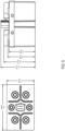
- FIG. 7 shows external views of an exterior view 702 of a contactor's arc envelope according to some embodiments of the present disclosure.
- FIG. 8 shows a flow chart of performance metrics for the force on an actuator plunger based on a plunger position in the coil described herein according to various embodiments.
- FIG. 9 shows the main components of an example yoke 900 according to some embodiments of the present disclosure.
- the yoke 900 includes a ferromagnetic upper yoke 902 and a ferromagnetic lower yoke 904.
- the ferromagnetic upper yoke 902 is an upper u-shaped yoke while the ferromagnetic lower yoke 904 is a flat yoke.
- the ferromagnetic lower yoke 904 includes an opening through which various components can pass. As an example, a plunger shaft of an actuator can pass through the opening.
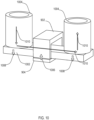
- FIG. 10 shows the yoke 900 mounted around a moveable contact 1002 according to some embodiments of the present disclosure.
- the ferromagnetic upper yoke 902 and ferromagnetic lower yoke 904 wrap around movable contact 1002 to help prevent levitation.
- the moveable contact 1002 is in contact with terminals 1004.
- arrow 1006 shows a direction of magnetic force
- arrows 1008 show a direction of levitation force
- arrows 1010 show a direction of current flow.
- the ferromagnetic upper yoke 902 is drawn to the ferromagnetic lower yoke 904 by magnetic force.
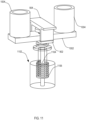
- FIG. 11 shows an example view of a contact actuator assembly with yokes included according to some embodiments of the present disclosure.
- the ferromagnetic lower yoke 904 contacts the actuator 1102.
- the ferromagnetic lower yoke 904 supports the moveable contact 1002 which is framed by the ferromagnetic upper yoke 902.
- the actuator assembly 1102 includes a plunger shaft 1104 applied force by a plunger spring 1106.
- the plunger shaft 1104 passes through an opening in the ferromagnetic lower yoke 902.
- the plunger shaft 1104 passes through an opening in the moveable contact 1002.
- the moveable contact 1002 conductively links the terminals 1004 to allow current to pass through the terminals 1004 via the moveable contact 1002.
- FIG. 12 shows a cross sectional view of a contactor 1200 with yoke design features according to some embodiments of the present disclosure.
- the contactor 1200 includes an actuator assembly including a plunger 1202 and plunger shaft 1104.
- a plunger spring 1106 surrounds the plunger shaft 1104 and is housed in an inner chamber of the plunger 1202.
- a standoff 1208 elevates the plunger shaft 1104.
- the plunger shaft 1104 passes through an opening in a moveable contact 1002.
- the moveable contact 906 passes through a yoke including a ferromagnetic upper yoke 902 and a ferromagnetic lower yoke 904.
- the yoke and actuator components are housed within an arc envelope 1210, such as a ceramic arc envelope.
- a terminal 1004 extends from the top of the contactor 1200.
- a lower portion of the contactor 1200 includes a coil bobbin 1212 housing the plunger 1202.
- Coil wire 1214 surrounds the coil bobbin 1212.
- the lower portion of the contactor 1200 is defined by a top core 1216 separator.
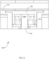
- FIG. 13 shows an example contactor 1300 side cross-sectional view according to some embodiments of the present disclosure.
- the contactor 1300 includes an arc envelope 1210 that supports the ferromagnetic upper yoke 902.
- the ferromagnetic lower yoke 904 is attached to an actuator.
- the moveable contact 906 rests on the ferromagnetic lower yoke 904.
- a plunger shaft 1104 passes through an opening in the moveable contact 1002.
- FIG. 14 shows an example contactor 1400 front cross-sectional view according to some embodiments of the present disclosure.
- a plunger shaft 1104 passes through and is elevated by a standoff 1208.
- the plunger shaft 1104 also passes through an opening in the ferromagnetic lower yoke 904 and the moveable contact 1002.
- the ferromagnetic upper yoke 902 is supported by an arc envelope 1210. Terminals 1004 contact the moveable contact 1002, allowing for current to pass through the terminals 1004 via the moveable contact 1002.
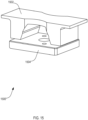
- FIG. 15 shows a chamfered yoke 1500 variation according to some embodiments of the present disclosure.
- the chamfered yoke 1500 includes a chamfered upper yoke 1502 and a lower yoke 1504.
- the lower yoke 1504 includes one or more openings to allow passage of other components, such as a plunger shaft 1104.
- Both the chamfered upper yoke 1502 and the lower yoke 1504 are ferromagnetic as can be appreciated.
- FIG. 16 shows a cross-sectional view of a contactor 1600 with a chamfered yoke 1500.
- the chamfered upper yoke 1502 is supported by an arc envelope 1602.
- a moveable contact 1002 rests on the lower yoke 1504.
- a plunger shaft 1104 passes through the openings in the lower yoke 1504 and the moveable contact 906.
- the chamfered upper yoke 1502 allows additional ferromagnetic mass, increasing the anti-levitation force, without interfering with actuator movement.
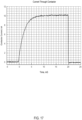
- FIG. 17 shows data from a 10kA, 20ms short-circuit test using a chamfered yoke design according to some embodiments of the present disclosure. Current is successfully passed through contactor using the chamfered yoke design.
- FIG. 18 shows a design variation of a contactor 1800 including an over-molded component 1802 in the actuator that isolates the high-voltage current carry circuit from the low-voltage coil circuit according to some embodiments of the present disclosure.
- the over-molded component 1802 is coupled to a plunger shaft 1104 of an actuator.
- the ferromagnetic lower yoke 904 sits atop the over-molded component 1802, with the moveable contact 1002 sitting on the ferromagnetic lower yoke 904.
- the ferromagnetic upper yoke 902 and the ferromagnetic lower yoke 904 frame or encircle the moveable contact 1002.
- FIG. 19 shows a cage component 1902 used to attach the ferromagnetic upper yoke 902 to the arc envelope 1602 according to some embodiments of the present disclosure.
- the cage component 1902 is coupled to the arc envelope 1602 and holds the ferromagnetic upper yoke 902 in place.
- the arc envelope 1602 includes openings for terminals 1004 that can contact a moveable contact 1002 after assembly.
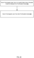
- FIG. 20 shows a flowchart of an example method of manufacture for a contactor having a magnetic yoke for improved switching performance in electromechanical contactors and relays according to some embodiments of the present disclosure.
- the method of FIG. 20 includes mounting 2002 a ferromagnetic upper yoke 902 in an inverted position above a moveable contact 1002 and separate from the moveable contact.
- mounting 2002 the ferromagnetic upper yoke 902 includes supporting the ferromagnetic upper yoke 902 by an arc envelope 1602 such as a ceramic arc envelope 1602.
- mounting 2002 the ferromagnetic upper yoke 902 includes coupling or attaching the ferromagnetic upper yoke 902 to a cage component 1902 that is coupled to the arc envelope 1602.
- the ferromagnetic upper yoke 902 is mounted above and separate from the moveable contact 1002 such that there is no direct physical coupling between the ferromagnetic upper yoke 902 and the moveable contact 1002.
- the method of FIG. 20 also includes mounting 2004 a ferromagnetic lower yoke 904 under the moveable contact 1002.
- the movable contact 1002 sits on or is attached to the ferromagnetic lower yoke 904.
- the ferromagnetic lower yoke 904 is attached or coupled to an actuator.
- the ferromagnetic upper yoke 902 and ferromagnetic upper yoke 904 are mounted inside a chamber that is hermetically sealed.
Landscapes
- Physics & Mathematics (AREA)
- Electromagnetism (AREA)
- Engineering & Computer Science (AREA)
- Manufacturing & Machinery (AREA)
- Arc-Extinguishing Devices That Are Switches (AREA)
- Electromagnets (AREA)
Abstract
Description
- This application claims priority to
U.S. Provisional Application No. 63/276,318, filed November 5, 2021 - The subject disclosure relates to component assemblies and methods of manufacturing component assemblies that include a magnetic yoke assembly for electromechanical contactors and relays.
- Electromechanical switching devices, such as contactors and relays, are designed to carry certain amount of electrical current for certain periods of time. Existing designs struggle to perform during very high current, short duration events commonly called short-circuits, which can cause the internal electrical contacts to separate destructively (commonly called contact levitation). One solution to this problem involves the use of ferromagnetic components, known as yokes or armatures, configured around the electrical contacts such that the short-circuit current induces a magnetic field and an attractive "anti-levitation" force between the ferromagnetic components that prevents the electrical contacts from separating. Existing applications using this approach mount the yoke surrounding the moveable electrical contact onto the moving assembly, increasing the mass of the moving assembly. This reduces operation speed and negatively impacts contactor/relay switching performance.
- Component assemblies and methods of manufacturing component assemblies that include a magnetic yoke assembly for electromechanical contactors and relays are disclosed. In a particular embodiment, a component assembly that includes a magnetic yoke assembly for electromechanical contactors and relays is described. In this embodiment, the magnetic yoke assembly includes a movable contact and a ferromagnetic upper yoke mounted above the moveable contact and separate from the moveable contact. The magnetic yoke assembly also includes a ferromagnetic lower yoke mounted under the moveable contact.
- In another embodiment, a method of manufacturing a component assembly that includes a magnetic yoke assembly for electromechanical contactors and relays is described. In this embodiment, the method includes mounting a ferromagnetic upper yoke above a moveable contact and separate from the moveable contact. The method also includes mounting a ferromagnetic lower yoke under the moveable contact.
- As will be explained in further detail below, by mounting the magnetic yoke separately from a moveable contact in a magnetic yoke assembly, the mass of a moveable contact assembly is reduced, which improves the operational speed and performance of a component assembly over component assemblies that include previously known designs of magnetic yoke assemblies.
-
-
FIG. 1 is a diagram of an example electromechanical contactor with a magnetic yoke assembly according to at least one embodiment of the present disclosure. -
FIG. 2 is a diagram illustrating current flow within an example electromechanical contactor with a magnetic yoke assembly according to at least one embodiment of the present disclosure. -
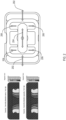
FIG. 3 is a diagram of various views of an example hermetic assembly of an electromechanical contactor with a magnetic yoke assembly according to at least one embodiment of the present disclosure. -
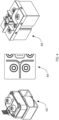
FIG. 4 is a diagram of various views of an example electromechanical contactor with a magnetic yoke assembly according to at least one embodiment of the present disclosure. -
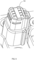
FIG. 5 is a diagram of an example Molex connector of an example electromechanical contactor with a magnetic yoke assembly according to at least one embodiment of the present disclosure. -
FIG. 6 is a diagram illustrating dimensions of an example electromechanical contactor with a magnetic yoke assembly according to at least one embodiment of the present disclosure. -
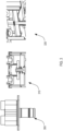
FIG. 7 is a diagram illustrating a view of an example external view of an arc envelope according to at least one embodiment of the present disclosure. -
FIG. 8 is a chart of performance metrics for force on an actuator plunger based on a plunger position in the coil according to at least one embodiment of the present disclosure. -
FIG. 9 is a diagram illustrating a view of a magnetic yoke assembly for electromechanical contactors and relays according to at least one embodiment of the present disclosure. -
FIG. 10 is a diagram illustrating a view of a magnetic yoke assembly for electromechanical contactors and relays according to at least one embodiment of the present disclosure. -
FIG. 11 is a diagram illustrating a view of a contact actuator of an example electromechanical contactor with a magnetic yoke assembly according to at least one embodiment of the present disclosure. -
FIG. 12 is a diagram illustrating a cross-sectional view of an example electromechanical contactor with a magnetic yoke assembly according to at least one embodiment of the present disclosure. -
FIG. 13 is a diagram illustrating a side cross-sectional view of an example electromechanical contactor with a magnetic yoke assembly according to at least one embodiment of the present disclosure. -
FIG. 14 is a diagram illustrating a front side cross-sectional view of an example electromechanical contactor with a magnetic yoke assembly according to at least one embodiment of the present disclosure. -
FIG. 15 is a diagram illustrating a chamfered yoke variation of a magnetic yoke assembly for electromechanical contactors and relays according to at least one embodiment of the present disclosure. -
FIG. 16 is a cross-sectional view of an example electromechanical contactor with a magnetic yoke assembly according to at least one embodiment of the present disclosure. -
FIG. 17 is a graph of data from a short-circuit test using a chamfered yoke variation of a magnetic yoke assembly according to at least one embodiment of the present disclosure. -
FIG. 18 is a diagram illustrating a cross-sectional view of an electromechanical contactor that includes a chamfered yoke variation of a magnetic yoke assembly according to at least one embodiment of the present disclosure. -
FIG. 19 is a diagram of a cage component of an electromechanical contactor that includes a magnetic yoke assembly with a chamfered yoke variation according to at least one embodiment of the present disclosure. -
FIG. 20 is a flowchart of an example method of manufacture for a magnetic yoke assembly for electromechanical contactors and relays according to at least one embodiment of the present disclosure. - The terminology used herein for the purpose of describing particular examples is not intended to be limiting for further examples. Whenever a singular form such as "a", "an" and "the" is used and using only a single element is neither explicitly or implicitly defined as being mandatory, further examples may also use plural elements to implement the same functionality. Likewise, when a functionality is subsequently described as being implemented using multiple elements, further examples may implement the same functionality using a single element or processing entity. It will be further understood that the terms "comprises", "comprising", "includes" and/or "including", when used, specify the presence of the stated features, integers, steps, operations, processes, acts, elements and/or components, but do not preclude the presence or addition of one or more other features, integers, steps, operations, processes, acts, elements, components and/or any group thereof.
- It will be understood that when an element is referred to as being "connected" or "coupled" to another element, the elements may be directly connected or coupled or via one or more intervening elements. If two elements A and B are combined using an "or", this is to be understood to disclose all possible combinations, i.e., only A, only B, as well as A and B. An alternative wording for the same combinations is "at least one of A and B". The same applies for combinations of more than two elements.
- Accordingly, while further examples are capable of various modifications and alternative forms, some particular examples thereof are shown in the figures and will subsequently be described in detail. However, this detailed description does not limit further examples to the particular forms described. Further examples may cover all modifications, equivalents, and alternatives falling within the scope of the disclosure. Like numbers refer to like or similar elements throughout the description of the figures, which may be implemented identically or in modified form when compared to one another while providing for the same or a similar functionality.
- In a particular embodiment, the use of ferromagnetic components to improve short-circuit performance in contactors involves mounting a u-shaped ferromagnetic yoke that surrounds the moveable contact onto the moving assembly.
- In a particular embodiment, the u-shaped yoke can also be chamfered to optimize the anti-levitation force. This allows further reduction of the lower yoke's mass.
- According to embodiments of the present disclosure, a u-shaped ferromagnetic yoke is mounted above a moveable current-carrying contact, under which is a second ferromagnetic component. During a high current event (ex. short-circuits), the inverted yoke magnetically attracts the second ferromagnetic component under the moveable contact, increasing contact force and maintaining continuity. According to one or more embodiments of the present disclosure, the yoke is mounted separately from the moveable contact, thus reducing mass on the moving assembly, and thereby increasing mechanism operating speed in comparison to similar designs. In addition, mounting the yoke separately from the moveable contact allows for short-circuit performance improvement without the negative impact to switching performance.
- In a particular embodiment, a magnetic yoke for improved switching performance in electromechanical contactors and relays includes bidirectional performance, improved corrosion resistance (CR) by removing plastic and coils from a sealed hermetic chamber. The yoke also includes modular performance - these requirements drive models used. Such requirements include make/break performance, levitation performance, isolated moveable, and aux normally open (NO) or normally closed (NC). The modular package includes housing, connectors, and mounting.
- For further explanation,
FIG. 1 illustrates an example embodiment of anelectromechanical contactor 100 according to at least one embodiment of the present disclosure. Thecontactor 100 includes anupper housing 102 andlower housing 106 that encloses the internal components of thecontactor 100, including the magnetic yoke assembly described in further detail below. Thecontactor 100 also includes aconnector 104. In some embodiments, theconnector 104 includes a Molex connector 104 (see, e.g.,FIG. 5 ). In other embodiments, theconnector 104 includes solder pins, flying leads, or other types of connectors as can be appreciated. Thecontactor 100 also includes one ormore terminals 108 for routing current through a moveable contact of a magnetic yoke assembly. - With respect to the bidirectional performance,
FIG. 2 illustrates that magnetic poles are in line with current direction, with non-sensitive installation. In the example ofFIG. 2 ,arrows 202 show a magnetic pole direction.Arrows 204 show a direction of a flow of current.Arrows 206 shows an arc direction pending current flow.FIG. 3 shows an examplehermetic assembly 300. In contrast to solutions for hermetic assemblies shown in thecross-sectional view 310, plastic has been completely removed from the sealed chamber of thehermetic assembly 300 to reduce CR as shown in thecross-sectional view 320. For isolated moveable and NC aux options, minimal plastic is used. In some implementations, the coil is removed from the hermetic chamber. This results in a chamber that is cleaner and has less moisture and contaminates. In this embodiment, changes in size/pin location do not impact the sealed design. - As is illustrated in the
example contactor 402 ofFIG. 4 , no housing is required according to at least one embodiment of the present disclosure. In some embodiments, a one-up (see contactor 404) or two-up design (see contactor 406) is used. In some embodiments, the yoke is mounted with a space efficient, top-down install. In some embodiments, the housing can be modified to fit custom mounting schemes with changes to the dimensional envelope as shown in the example dimensions shown inFIG. 6 .FIG. 7 shows external views of anexterior view 702 of a contactor's arc envelope according to some embodiments of the present disclosure.FIG. 8 shows a flow chart of performance metrics for the force on an actuator plunger based on a plunger position in the coil described herein according to various embodiments. -
FIG. 9 shows the main components of anexample yoke 900 according to some embodiments of the present disclosure. Theyoke 900 includes a ferromagneticupper yoke 902 and a ferromagneticlower yoke 904. The ferromagneticupper yoke 902 is an upper u-shaped yoke while the ferromagneticlower yoke 904 is a flat yoke. In some embodiments, the ferromagneticlower yoke 904 includes an opening through which various components can pass. As an example, a plunger shaft of an actuator can pass through the opening. -
FIG. 10 shows theyoke 900 mounted around amoveable contact 1002 according to some embodiments of the present disclosure. As shown inFIG. 10 , the ferromagneticupper yoke 902 and ferromagneticlower yoke 904 wrap aroundmovable contact 1002 to help prevent levitation. Themoveable contact 1002 is in contact withterminals 1004. In this example embodiment,arrow 1006 shows a direction of magnetic force,arrows 1008 show a direction of levitation force, andarrows 1010 show a direction of current flow. During a high current event, the ferromagneticupper yoke 902 is drawn to the ferromagneticlower yoke 904 by magnetic force. -
FIG. 11 shows an example view of a contact actuator assembly with yokes included according to some embodiments of the present disclosure. As shown inFIG. 11 , the ferromagneticlower yoke 904 contacts theactuator 1102. The ferromagneticlower yoke 904 supports themoveable contact 1002 which is framed by the ferromagneticupper yoke 902. Theactuator assembly 1102 includes aplunger shaft 1104 applied force by aplunger spring 1106. In some embodiments, theplunger shaft 1104 passes through an opening in the ferromagneticlower yoke 902. In some embodiments, theplunger shaft 1104 passes through an opening in themoveable contact 1002. Moreover, in some embodiments, when theplunger shaft 1104 is in an actuated state, themoveable contact 1002 conductively links theterminals 1004 to allow current to pass through theterminals 1004 via themoveable contact 1002. -
FIG. 12 shows a cross sectional view of acontactor 1200 with yoke design features according to some embodiments of the present disclosure. Thecontactor 1200 includes an actuator assembly including aplunger 1202 andplunger shaft 1104. Aplunger spring 1106 surrounds theplunger shaft 1104 and is housed in an inner chamber of theplunger 1202. Astandoff 1208 elevates theplunger shaft 1104. - The
plunger shaft 1104 passes through an opening in amoveable contact 1002. Themoveable contact 906 passes through a yoke including a ferromagneticupper yoke 902 and a ferromagneticlower yoke 904. The yoke and actuator components are housed within anarc envelope 1210, such as a ceramic arc envelope. A terminal 1004 extends from the top of thecontactor 1200. A lower portion of thecontactor 1200 includes acoil bobbin 1212 housing theplunger 1202.Coil wire 1214 surrounds thecoil bobbin 1212. The lower portion of thecontactor 1200 is defined by atop core 1216 separator. -
FIG. 13 shows anexample contactor 1300 side cross-sectional view according to some embodiments of the present disclosure. As shown in the example side cross-sectional view, thecontactor 1300 includes anarc envelope 1210 that supports the ferromagneticupper yoke 902. The ferromagneticlower yoke 904 is attached to an actuator. Themoveable contact 906 rests on the ferromagneticlower yoke 904. Aplunger shaft 1104 passes through an opening in themoveable contact 1002. -
FIG. 14 shows an example contactor 1400 front cross-sectional view according to some embodiments of the present disclosure. As shown inFIG. 14 , aplunger shaft 1104 passes through and is elevated by astandoff 1208. Theplunger shaft 1104 also passes through an opening in the ferromagneticlower yoke 904 and themoveable contact 1002. The ferromagneticupper yoke 902 is supported by anarc envelope 1210.Terminals 1004 contact themoveable contact 1002, allowing for current to pass through theterminals 1004 via themoveable contact 1002. -
FIG. 15 shows achamfered yoke 1500 variation according to some embodiments of the present disclosure. The chamferedyoke 1500 includes a chamferedupper yoke 1502 and alower yoke 1504. As shown, thelower yoke 1504 includes one or more openings to allow passage of other components, such as aplunger shaft 1104. Both the chamferedupper yoke 1502 and thelower yoke 1504 are ferromagnetic as can be appreciated. -
FIG. 16 shows a cross-sectional view of acontactor 1600 with achamfered yoke 1500. In theexample contactor 1600, the chamferedupper yoke 1502 is supported by anarc envelope 1602. Amoveable contact 1002 rests on thelower yoke 1504. Aplunger shaft 1104 passes through the openings in thelower yoke 1504 and themoveable contact 906. The chamferedupper yoke 1502 allows additional ferromagnetic mass, increasing the anti-levitation force, without interfering with actuator movement.FIG. 17 shows data from a 10kA, 20ms short-circuit test using a chamfered yoke design according to some embodiments of the present disclosure. Current is successfully passed through contactor using the chamfered yoke design. -
FIG. 18 shows a design variation of a contactor 1800 including anover-molded component 1802 in the actuator that isolates the high-voltage current carry circuit from the low-voltage coil circuit according to some embodiments of the present disclosure. As shown, theover-molded component 1802 is coupled to aplunger shaft 1104 of an actuator. The ferromagneticlower yoke 904 sits atop theover-molded component 1802, with themoveable contact 1002 sitting on the ferromagneticlower yoke 904. The ferromagneticupper yoke 902 and the ferromagneticlower yoke 904 frame or encircle themoveable contact 1002. -
FIG. 19 shows acage component 1902 used to attach the ferromagneticupper yoke 902 to thearc envelope 1602 according to some embodiments of the present disclosure. Thecage component 1902 is coupled to thearc envelope 1602 and holds the ferromagneticupper yoke 902 in place. As shown, thearc envelope 1602 includes openings forterminals 1004 that can contact amoveable contact 1002 after assembly. -
FIG. 20 shows a flowchart of an example method of manufacture for a contactor having a magnetic yoke for improved switching performance in electromechanical contactors and relays according to some embodiments of the present disclosure. The method ofFIG. 20 includes mounting 2002 a ferromagneticupper yoke 902 in an inverted position above amoveable contact 1002 and separate from the moveable contact. In some embodiments, mounting 2002 the ferromagneticupper yoke 902 includes supporting the ferromagneticupper yoke 902 by anarc envelope 1602 such as aceramic arc envelope 1602. In some embodiments, mounting 2002 the ferromagneticupper yoke 902 includes coupling or attaching the ferromagneticupper yoke 902 to acage component 1902 that is coupled to thearc envelope 1602. The ferromagneticupper yoke 902 is mounted above and separate from themoveable contact 1002 such that there is no direct physical coupling between the ferromagneticupper yoke 902 and themoveable contact 1002. - The method of
FIG. 20 also includes mounting 2004 a ferromagneticlower yoke 904 under themoveable contact 1002. Thus, themovable contact 1002 sits on or is attached to the ferromagneticlower yoke 904. In some embodiments, the ferromagneticlower yoke 904 is attached or coupled to an actuator. In some embodiments, the ferromagneticupper yoke 902 and ferromagneticupper yoke 904 are mounted inside a chamber that is hermetically sealed. - It will be understood from the foregoing description that modifications and changes may be made in various embodiments of the present disclosure without departing from its true spirit. The descriptions in this specification are for purposes of illustration only and are not to be construed in a limiting sense. The scope of the present disclosure is limited only by the language of the following claims.
Claims (15)
- A component assembly including a magnetic yoke assembly for electromechanical contactors and relays, the magnetic yoke assembly including:a moveable contact;a ferromagnetic upper yoke mounted above the moveable contact and separate from the moveable contact; anda ferromagnetic lower yoke mounted under the moveable contact.
- The component assembly of claim 1, further comprising a plurality of terminals.
- The component assembly of claim 2, wherein the movable contact contacts the plurality of terminals when the contactor is in an actuated state.
- The component assembly of any one of claims 1 to 3, further comprising an arc envelope supporting the ferromagnetic upper yoke; and optionally; the arc envelope comprises a ceramic arc envelope.
- The component assembly of claim 4, further comprising a claw component coupled to the arc envelope, wherein the ferromagnetic upper yoke is coupled to the claw component.
- The component assembly of any one of claims 1 to 5, further comprising a housing.
- The component assembly of any one of claims 1 to 6 or the method of claim 14 or 15, wherein the ferromagnetic upper yoke comprises a chamfered yoke.
- The component assembly of any one of claims 1 to 7, further comprising an over-molded component isolating a high-voltage current carry circuit from a low-voltage coil circuit.
- The component assembly of any one of claims 1 to 8, wherein the ferromagnetic lower yoke is coupled to the over-molded component.
- The component assembly of any one of claims 1 to 9, further comprising an actuator, wherein the ferromagnetic lower yoke is attached to the actuator.
- The component contactor of any one of claims 1 to 10, wherein the moveable contact comprises an opening and wherein a plunger shaft of the actuator passes through the opening.
- The component assembly of any one of claims 1 to 11, further comprising a hermetically sealed chamber housing the magnetic yoke assembly.
- The component assembly of any one of claims 1 to 12, wherein the ferromagnetic upper yoke comprises a u-shaped yoke and the ferromagnetic lower yoke comprises a flat yoke.
- A method of manufacturing a component assembly that includes a magnetic yoke assembly for electromechanical for an electromechanical contactor, the method comprising:mounting a ferromagnetic upper yoke above the moveable contact and separate from the moveable contact; andmounting a ferromagnetic lower yoke under the moveable contact.
- The method of claim 15, wherein the ferromagnetic upper yoke and the ferromagnetic upper yoke are mounted in a hermetically sealed chamber; orwherein mounting the ferromagnetic upper yoke comprises supporting the ferromagnetic upper yoke by an arc envelope; orwherein mounting the ferromagnetic upper yoke comprises attaching the ferromagnetic upper yoke to a claw component; orwherein the movable contact contacts a plurality of terminals when the contactor is in an actuated state.
Applications Claiming Priority (1)
| Application Number | Priority Date | Filing Date | Title |
|---|---|---|---|
| US202163276318P | 2021-11-05 | 2021-11-05 |
Publications (1)
| Publication Number | Publication Date |
|---|---|
| EP4177917A1 true EP4177917A1 (en) | 2023-05-10 |
Family
ID=80623520
Family Applications (1)
| Application Number | Title | Priority Date | Filing Date |
|---|---|---|---|
| EP22159299.1A Pending EP4177917A1 (en) | 2021-11-05 | 2022-02-28 | Component assemblies and methods of manufacturing component assemblies that include a magnetic yoke assembly for electromechanical contactors and relays |
Country Status (4)
| Country | Link |
|---|---|
| US (1) | US12531199B2 (en) |
| EP (1) | EP4177917A1 (en) |
| KR (1) | KR20230065862A (en) |
| CN (1) | CN116092883A (en) |
Citations (4)
| Publication number | Priority date | Publication date | Assignee | Title |
|---|---|---|---|---|
| EP3139396A1 (en) * | 2015-09-04 | 2017-03-08 | Omron Corporation | Contact switching device |
| WO2020241969A1 (en) * | 2019-05-29 | 2020-12-03 | 엘에스일렉트릭㈜ | Direct current relay and manufacturing method therefor |
| WO2021022822A1 (en) * | 2019-08-08 | 2021-02-11 | 东莞市中汇瑞德电子股份有限公司 | Anti-short circuit structure of high-capacity relay |
| EP3846194A1 (en) * | 2018-08-31 | 2021-07-07 | LS Electric Co., Ltd. | Direct current relay |
Family Cites Families (10)
| Publication number | Priority date | Publication date | Assignee | Title |
|---|---|---|---|---|
| US3887888A (en) * | 1973-04-04 | 1975-06-03 | Arrow Hart Inc | High current switch |
| FR2517463A1 (en) * | 1981-11-30 | 1983-06-03 | Telemecanique Electrique | CONTACTOR PROVIDED WITH SELF-PROTECTING MEANS AGAINST THE EFFECTS OF REPULSION FORCES BETWEEN THE CONTACTS, AND ITS ASSOCIATION WITH A DEVICE FOR CUTTING AND LIMITING SHORT CIRCUIT CURRENTS |
| FR2559308B1 (en) * | 1984-02-03 | 1986-10-17 | Telemecanique Electrique | CONTACT EQUIPPED WITH A MAGNETIC COMPENSATOR WITH ADJUSTABLE RELEASE THRESHOLD AND CIRCUIT-BREAKER USING SUCH A CONTACT |
| JP5206157B2 (en) * | 2008-06-30 | 2013-06-12 | オムロン株式会社 | Electromagnetic relay |
| US20140002215A1 (en) * | 2012-06-29 | 2014-01-02 | Siemens Industry, Inc. | Electrical contact apparatus, assemblies, and methods of operation |
| CN108417448B (en) | 2013-06-28 | 2021-03-05 | 松下知识产权经营株式会社 | Contact device and electromagnetic relay having the same |
| KR101545893B1 (en) | 2014-01-28 | 2015-08-20 | 엘에스산전 주식회사 | Relay |
| KR102689914B1 (en) | 2019-08-28 | 2024-07-31 | 엘에스일렉트릭(주) | Arc path forming part and direct current relay include the same |
| CN116097384A (en) | 2020-06-16 | 2023-05-09 | 吉加瓦有限责任公司 | Contactor with integrated drive shaft and yoke |
| JP7721688B2 (en) | 2021-06-08 | 2025-08-12 | ティーディーケイ・エレクトロニクス・アクチェンゲゼルシャフト | Switching Device |
-
2022
- 2022-01-31 US US17/588,865 patent/US12531199B2/en active Active
- 2022-02-24 KR KR1020220024062A patent/KR20230065862A/en active Pending
- 2022-02-28 EP EP22159299.1A patent/EP4177917A1/en active Pending
- 2022-02-28 CN CN202210186158.7A patent/CN116092883A/en active Pending
Patent Citations (6)
| Publication number | Priority date | Publication date | Assignee | Title |
|---|---|---|---|---|
| EP3139396A1 (en) * | 2015-09-04 | 2017-03-08 | Omron Corporation | Contact switching device |
| EP3846194A1 (en) * | 2018-08-31 | 2021-07-07 | LS Electric Co., Ltd. | Direct current relay |
| WO2020241969A1 (en) * | 2019-05-29 | 2020-12-03 | 엘에스일렉트릭㈜ | Direct current relay and manufacturing method therefor |
| EP3979289A1 (en) * | 2019-05-29 | 2022-04-06 | LS Electric Co., Ltd. | Direct current relay and manufacturing method therefor |
| WO2021022822A1 (en) * | 2019-08-08 | 2021-02-11 | 东莞市中汇瑞德电子股份有限公司 | Anti-short circuit structure of high-capacity relay |
| EP4012741A1 (en) * | 2019-08-08 | 2022-06-15 | Dongguan Zhonghui Ruide Electronics Co., Ltd | Anti-short circuit structure of high-capacity relay |
Also Published As
| Publication number | Publication date |
|---|---|
| US12531199B2 (en) | 2026-01-20 |
| CN116092883A (en) | 2023-05-09 |
| KR20230065862A (en) | 2023-05-12 |
| US20230145346A1 (en) | 2023-05-11 |
Similar Documents
| Publication | Publication Date | Title |
|---|---|---|
| EP3139396B1 (en) | Contact switching device | |
| CN218385036U (en) | Zxfoom | |
| CN218385019U (en) | Relay device | |
| CN101438364A (en) | Electromagnetic relay | |
| CN101630567A (en) | Electromagnet device | |
| CN103377856A (en) | Electromagnetic relay | |
| CN218385043U (en) | Relay device | |
| CN113646859B (en) | Contactor with arc suppressor | |
| CN218730704U (en) | Relay with a movable contact | |
| CN119626845B (en) | relay | |
| KR102917588B1 (en) | Relay | |
| CN118800622A (en) | Relay | |
| JP7782789B2 (en) | relay | |
| KR20240151649A (en) | Relay | |
| JP4281251B2 (en) | Electromagnetic relay | |
| KR20240151650A (en) | Relay | |
| CN220963163U (en) | Relay device | |
| KR20170092051A (en) | Relay | |
| CN220963168U (en) | Relay device | |
| CN219497660U (en) | Relay device | |
| EP4177917A1 (en) | Component assemblies and methods of manufacturing component assemblies that include a magnetic yoke assembly for electromechanical contactors and relays | |
| CN111295729B (en) | Electromagnetic relay and electromagnetic device | |
| CN117877930A (en) | Relay | |
| KR102888015B1 (en) | Relay | |
| CN220963167U (en) | Relay device |
Legal Events
| Date | Code | Title | Description |
|---|---|---|---|
| PUAI | Public reference made under article 153(3) epc to a published international application that has entered the european phase |
Free format text: ORIGINAL CODE: 0009012 |
|
| STAA | Information on the status of an ep patent application or granted ep patent |
Free format text: STATUS: THE APPLICATION HAS BEEN PUBLISHED |
|
| AK | Designated contracting states |
Kind code of ref document: A1 Designated state(s): AL AT BE BG CH CY CZ DE DK EE ES FI FR GB GR HR HU IE IS IT LI LT LU LV MC MK MT NL NO PL PT RO RS SE SI SK SM TR |
|
| P01 | Opt-out of the competence of the unified patent court (upc) registered |
Effective date: 20230708 |
|
| STAA | Information on the status of an ep patent application or granted ep patent |
Free format text: STATUS: REQUEST FOR EXAMINATION WAS MADE |
|
| 17P | Request for examination filed |
Effective date: 20231109 |
|
| RBV | Designated contracting states (corrected) |
Designated state(s): AL AT BE BG CH CY CZ DE DK EE ES FI FR GB GR HR HU IE IS IT LI LT LU LV MC MK MT NL NO PL PT RO RS SE SI SK SM TR |
|
| STAA | Information on the status of an ep patent application or granted ep patent |
Free format text: STATUS: EXAMINATION IS IN PROGRESS |
|
| 17Q | First examination report despatched |
Effective date: 20250121 |