EP4177698B1 - Sensor system for fluids - Google Patents
Sensor system for fluids Download PDFInfo
- Publication number
- EP4177698B1 EP4177698B1 EP22196366.3A EP22196366A EP4177698B1 EP 4177698 B1 EP4177698 B1 EP 4177698B1 EP 22196366 A EP22196366 A EP 22196366A EP 4177698 B1 EP4177698 B1 EP 4177698B1
- Authority
- EP
- European Patent Office
- Prior art keywords
- sensors
- conductivity
- sensor
- circuit board
- electronic circuit
- Prior art date
- Legal status (The legal status is an assumption and is not a legal conclusion. Google has not performed a legal analysis and makes no representation as to the accuracy of the status listed.)
- Active
Links
Images

Classifications
-
- G—PHYSICS
- G05—CONTROLLING; REGULATING
- G05D—SYSTEMS FOR CONTROLLING OR REGULATING NON-ELECTRIC VARIABLES
- G05D11/00—Control of flow ratio
- G05D11/02—Controlling ratio of two or more flows of fluid or fluent material
- G05D11/13—Controlling ratio of two or more flows of fluid or fluent material characterised by the use of electric means
- G05D11/135—Controlling ratio of two or more flows of fluid or fluent material characterised by the use of electric means by sensing at least one property of the mixture
-
- G—PHYSICS
- G01—MEASURING; TESTING
- G01N—INVESTIGATING OR ANALYSING MATERIALS BY DETERMINING THEIR CHEMICAL OR PHYSICAL PROPERTIES
- G01N27/00—Investigating or analysing materials by the use of electric, electrochemical, or magnetic means
- G01N27/02—Investigating or analysing materials by the use of electric, electrochemical, or magnetic means by investigating impedance
- G01N27/04—Investigating or analysing materials by the use of electric, electrochemical, or magnetic means by investigating impedance by investigating resistance
- G01N27/06—Investigating or analysing materials by the use of electric, electrochemical, or magnetic means by investigating impedance by investigating resistance of a liquid
- G01N27/07—Construction of measuring vessels; Electrodes therefor
-
- G—PHYSICS
- G01—MEASURING; TESTING
- G01N—INVESTIGATING OR ANALYSING MATERIALS BY DETERMINING THEIR CHEMICAL OR PHYSICAL PROPERTIES
- G01N27/00—Investigating or analysing materials by the use of electric, electrochemical, or magnetic means
- G01N27/02—Investigating or analysing materials by the use of electric, electrochemical, or magnetic means by investigating impedance
- G01N27/04—Investigating or analysing materials by the use of electric, electrochemical, or magnetic means by investigating impedance by investigating resistance
- G01N27/045—Circuits
- G01N27/046—Circuits provided with temperature compensation
-
- B—PERFORMING OPERATIONS; TRANSPORTING
- B01—PHYSICAL OR CHEMICAL PROCESSES OR APPARATUS IN GENERAL
- B01F—MIXING, e.g. DISSOLVING, EMULSIFYING OR DISPERSING
- B01F35/00—Accessories for mixers; Auxiliary operations or auxiliary devices; Parts or details of general application
- B01F35/20—Measuring; Control or regulation
- B01F35/21—Measuring
- B01F35/211—Measuring of the operational parameters
- B01F35/2112—Level of material in a container or the position or shape of the upper surface of the material
-
- B—PERFORMING OPERATIONS; TRANSPORTING
- B01—PHYSICAL OR CHEMICAL PROCESSES OR APPARATUS IN GENERAL
- B01F—MIXING, e.g. DISSOLVING, EMULSIFYING OR DISPERSING
- B01F35/00—Accessories for mixers; Auxiliary operations or auxiliary devices; Parts or details of general application
- B01F35/20—Measuring; Control or regulation
- B01F35/21—Measuring
- B01F35/211—Measuring of the operational parameters
- B01F35/2115—Temperature
-
- B—PERFORMING OPERATIONS; TRANSPORTING
- B01—PHYSICAL OR CHEMICAL PROCESSES OR APPARATUS IN GENERAL
- B01F—MIXING, e.g. DISSOLVING, EMULSIFYING OR DISPERSING
- B01F35/00—Accessories for mixers; Auxiliary operations or auxiliary devices; Parts or details of general application
- B01F35/20—Measuring; Control or regulation
- B01F35/21—Measuring
- B01F35/2133—Electrical conductivity or dielectric constant of the mixture
Definitions
- the invention relates to a sensor system, particularly for monitoring the mixing of at least two fluids.
- Automated analyser systems for use in clinical diagnostics and life sciences are produced by a number of companies.
- STRATEC ® SE Birkenfeld, Germany
- solutions mainly sodium chlorite or potassium chlorite solutions with surfactants
- a concentrate and water can either be supplied ready-mixed to the instrument or mixed on the instrument from a concentrate and water.
- a pump e.g. a peristaltic pump.
- a sensor is necessary for monitoring and/or control.
- Solutions for washing purposes in an automated analyser system may be prepared outside the system under controlled conditions, either manually, with very precise pumps, or e.g. by weighing the individual components. This approach requires additional facilities for preparing and providing the required solutions.
- premixed buffer solutions are disadvantageous with respect to their storage because the solutions are water based.
- a mixing ratio of concentrate and water between 1:10 and 1:20 is commonly used.
- the sensors available in the field are either too large or too expensive or both for (serial) use in diagnostic devices.
- the use of metallic electrodes in process liquids of analytical instruments is not desired, since interactions with the liquid may occur and thus influence the results of the analysis.
- WO 2018/237376 A1 relates to a medicament preparation system which includes a disposable cartridge with a flow path.
- Various sensors may be placed on the cartridge to measure qualities of the fluid flowing through the flow path. The sensors are placed in precise locations using various approaches that make manufacturing of the cartridge efficient and repeatable.
- a drain line that is susceptible to fouling may be preattached and various approaches are used to remove or reduce the fouling.
- An elastomeric contact can also be present in the medical preparation system and used in a conductivity measurement subsystem.
- WO 2006/113177 A2 discloses various improvements in the field of surface plasmon resonance (SPR) sensing systems.
- SPR surface plasmon resonance
- One improvement relates to a portable SPR sensing system, e.g., a system contained within a suitcase that can be hand-carried to a monitoring site.
- Another improvement relates to a portable, cartridge based SPR sensing system. In this system, selected portions of the system's electrical and fluidics systems are allocated between a base unit and a removable/disposable cartridge.
- Other improvements relate to methods or protocols for operating an SPR sensing system. Such methods provide for the elimination of false positives and increased sensitivity, e.g., by using secondary antibodies with specificity for different target epitopes and by sensor element redundancy.
- protocols are provided for the detection of small molecules. Such protocols may employ a competition type assay where the presence of the analyte inhibits the binding of antibodies to surface immobilized analyte, or a displacement assay, where antibodies bound to the analyte on the sensor surface are displaced by free analyte.
- the present invention provides a sensor system for fluids, comprising vertically arranged level sensors, characterized in that
- all sensors are made of a conductive plastic.
- the two outer electrodes of the conductivity sensors apply a defined current and the two inner electrodes conductivity sensors measure the current for determining the conductivity of the fluid.
- the at least two level sensors are optical sensors.
- each tip of the at least two level sensors is made of a transparent material
- the tip of a level sensor can be a prism.
- the system according to the invention may further encompass that the temperature sensor is located below the conductivity sensor.
- the temperature sensor is thermally insulated from the injection molded housing.
- Another object of the invention is a method for monitoring the mixture of fluids, comprising the steps of
- the method may further comprise the step of adjusting the ratio of the two fluids according to the determined conductivity if the measured conductivity is outside the pre-defined range.
- a fluid within the meaning of the present disclosure relates to a liquid which may comprise solid or gaseous compounds.
- the term controller shall be understood within the meaning of the present invention as a device that is able to receive and send electronic signals from or to the sensor system.
- a controller can also be an automated analyser system to which the sensor system is connected.
- the connector of a sensor system according to the present disclosure may also be used for connecting several sensor systems.
- the present disclosure provides a low-cost sensor for analytical instruments.
- the sensor uses electrodes made of conductive plastic for measuring the conductivity instead of the commonly used metal electrodes.
- the sensor further comprises level sensors for monitoring the filling level in the container and a temperature sensor.
- the sensors of a device according to the present disclosure are arranged in a very specific manner to obtain a reliable sensing but keep the complexity and costs of the device low.
- the number of sensors is minimized in a device according to the present invention and said prior art document does not guide a skilled person to the chosen arrangement of sensors of a device of the present invention.
- the device of US 2019/056321 A1 provides four connectors for the circuit board. Said place of the PCB is used in a device according to the present invention for the four horizontally arranged conductivity sensors, so that the arrangement of the sensors according to the present invention would not be possible coming from a device according to US 2019/056321 A1 as a starting point.
- the conductivity sensor of a sensor according to the present disclosure is based on the use of four electrodes which are arranged in a horizontal row of all four sensors next to another (four-wire measuring technique).
- the conductivity sensors are arranged below the lower level sensor of the two vertically above another arranged level sensors. Such an arrangement guarantees that the conductivity sensors are only used when they are covered by a liquid, which is the case when the lower level sensor detects a liquid.
- a defined current is applied to the liquid via the two outer electrodes (conductivity sensors), and the voltage generated by the current flow is measured with high resistance using the two inner electrodes (conductivity sensors).
- the level sensors of a sensor according to the present disclosure operate optically according to the total reflection principle.
- Light is emitted into a tip of the sensor.
- the tip of the sensor is made of a transparent material and the inner surfaces of the tip are angled in a manner so that the emitted light is reflected onto a receiver if there is air around the transparent tip of the sensor (total internal reflection). However, if a liquid is surrounding the tip of the sensor, the light exits the sensor, and the receiver will not receive reflected light.
- At least two of such level sensors are provided, one may detect a minimum liquid level at which the conductivity electrodes are guaranteed to still be in the liquid and another level sensor is used to detect a maximum level to prevent a container from overflowing. Further level sensors may be used for determining intermediate fluid levels.
- the conductivity of liquids depends strongly on the temperature of the liquid. Temperature compensation is thus essential for a precise conductivity measurement.
- the temperature sensor is located at the lower end of the conductivity sensor, thermally insulated as far as possible to reduce incorrect measurements due to a self-heating of the sensor.
- the conductivity sensor remains permanently in the liquid so that the protection of the installed electronics is elementary.
- the sensor shall be manufactured cost-effectively in large quantities. Therefore, the sensor comprises a plastic injection molded housing, which is additionally filled with a hot melt potting compound.
- the sensor may be directly molded during injection molding, i.e. inserted into the injection mold, the hotmelt potting compound protects the electronics from temperature and pressure during injection molding and also protects against penetration of the liquid.
- Direct “overmolding” achieves a housing without potentially critical (in terms of water ingress) joints and generates a tight connection to the electrodes and level sensors protruding into the liquid.
- the electrodes for conductivity measurement and the prisms of the optical level sensors have so-called "melting ribs" which melt during injection molding and thus ensure a tight connection.
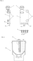
- FIG.1 shows in the middle a vertical arranged sensor system 10 with a view on a front plate 15 of an injection molded housing 16. Sectional planes A-A, B-B and C-C are indicated.
- a connector 4 is arranged on top of the sensor for connecting the sensor system 10 with a cable (not shown) to a controller (not shwn).
- Two level sensors 3 are arranged above each other.
- the four electrodes of the conductivity sensors 20 are arranged in a row at the lower end of the front plate 15.
- the body of the injection molded housing 16 is filled with a hot melt compound 25 for embedding the level sensors 3, conductivity sensors 20 together with an electronic circuit board 5.
- FIG. 2 shows a sectional view through a level sensor 3 which is connected to the electronic circuit board 5.
- a transmitter 31 and a receiver 33 are arranged next to each other on the electronic circuit board 3.
- Transmitter 31 emits light in the direction of tip 35 of the level sensor 3.
- Tip 35 of the level sensor is a prism 37 so that light will be reflected onto receiver 33 if air surrounds tip 35 of level sensor 3. In case that a fluid like a liquid surrounds prism 37 the light will no longer - at least partly - be reflected onto receiver 33.
- Melting ribs 39 are arranged on the outer surface below the tip 35 of level sensor 3. They are used for fixation of level sensor 3 in the injection molded housing 16 during injection molding.
- FIG. 3 shows the electronic circuit board 5 without injection molded housing and hot melt compound in a side view (left), a front view (upper right), and in a view from below without connector 4 (lower part).
- Level sensors 3, conductivity sensors 20, temperature sensor 40 and connector 4 are all arranged onto and connected to the electronic circuit board
- FIG. 4 shows a sensor system 10 which is arranged in a container 50.
- Glassy carbon is an engineering material that does not occur naturally and consists of pure carbon combining the positive properties of vitreous and ceramic materials. The most important properties of said material relate to its good electrical conductivity, high corrosion resistance, high rigidity and strength, extremely good temperature resistance, good biocompatibility and low gas and liquid permeability. The rigidity of glassy carbon is also related to a demanding machining in manufacturing electrodes.
Landscapes
- Chemical & Material Sciences (AREA)
- General Physics & Mathematics (AREA)
- Physics & Mathematics (AREA)
- Analytical Chemistry (AREA)
- Chemical Kinetics & Catalysis (AREA)
- Electrochemistry (AREA)
- Health & Medical Sciences (AREA)
- Life Sciences & Earth Sciences (AREA)
- Biochemistry (AREA)
- General Health & Medical Sciences (AREA)
- Immunology (AREA)
- Pathology (AREA)
- Automation & Control Theory (AREA)
- Engineering & Computer Science (AREA)
- Investigating Or Analyzing Materials By The Use Of Electric Means (AREA)
Description
- The invention relates to a sensor system, particularly for monitoring the mixing of at least two fluids.
- Automated analyser systems for use in clinical diagnostics and life sciences are produced by a number of companies. For example, STRATEC® SE, Birkenfeld, Germany, produces a number of devices for specimen handling and detection for use in automated analyser systems and other laboratory instrumentation.
- STRATEC® designs and manufactures automated analytical systems in the field of in vitro diagnostics (IVD), which use a number of individual instrument components to process diagnostic assays. Wash buffer which are aqueous solutions are required in automated analyser systems for processing samples, among other things.
- These solutions (mainly sodium chlorite or potassium chlorite solutions with surfactants) can either be supplied ready-mixed to the instrument or mixed on the instrument from a concentrate and water. When mixing in the unit, both concentrate and water are each supplied into a container by a pump, e.g. a peristaltic pump. In order to keep the mixing ratio constant within the specified limits and to be able to detect failures or faulty delivery rates of a pump, a sensor is necessary for monitoring and/or control.
- Solutions for washing purposes in an automated analyser system may be prepared outside the system under controlled conditions, either manually, with very precise pumps, or e.g. by weighing the individual components. This approach requires additional facilities for preparing and providing the required solutions.
- Alternatively, very precise conductivity sensors which have been developed for process technology are available in the field. These sensors are also usually mechanically very robust which results in an increased weight and size. Said sensors usually measure the conductivity of the liquid by means of metallic electrodes that are immersed in the liquid, alternatively there are also inductive sensors. With these, an electrical voltage is coupled into the liquid by means of a coil and the resulting current flow in the liquid is measured with a second coil.
- The use of premixed buffer solutions is disadvantageous with respect to their storage because the solutions are water based. When mixing a buffer on the unit from a concentrate and water, a mixing ratio of concentrate and water between 1:10 and 1:20 is commonly used.
- The sensors available in the field are either too large or too expensive or both for (serial) use in diagnostic devices. In addition, the use of metallic electrodes in process liquids of analytical instruments is not desired, since interactions with the liquid may occur and thus influence the results of the analysis.
- Published U.S. patent application
US 2019/056321 A1 discloses an integrated in a sensor device, wherein a plurality of detection arrangements of various types, comprising at least a level-sensing arrangement and an optical arrangement for detection of one or more characteristics of the substance, and possibly also a temperature-sensing arrangement, with these arrangements that are operatively associated to one and the same casing or assembly body. The arrangement and the number of the sensors of a device according toUS 2019/056321 A1 appear to be disadvantageous in terms of making the device complex. - Published International application
WO 2018/237376 A1 relates to a medicament preparation system which includes a disposable cartridge with a flow path. Various sensors may be placed on the cartridge to measure qualities of the fluid flowing through the flow path. The sensors are placed in precise locations using various approaches that make manufacturing of the cartridge efficient and repeatable. A drain line that is susceptible to fouling may be preattached and various approaches are used to remove or reduce the fouling. An elastomeric contact can also be present in the medical preparation system and used in a conductivity measurement subsystem. - Published U.S. patent application
US 2009/012452 A1 teaches an dialysis system instrument which includes a dialysis instrument, a disposable pumping and valving cassette apparatus operable with pumping and valving actuators of the dialysis instrument, the disposable cassette including an electronic cell and electronics associated with the electronic cell, the electronics configured to determine an electrical property of a solution flowing through the electronic cell of the disposable apparatus. - Published International patent application
WO 2006/113177 A2 discloses various improvements in the field of surface plasmon resonance (SPR) sensing systems. One improvement relates to a portable SPR sensing system, e.g., a system contained within a suitcase that can be hand-carried to a monitoring site. Another improvement relates to a portable, cartridge based SPR sensing system. In this system, selected portions of the system's electrical and fluidics systems are allocated between a base unit and a removable/disposable cartridge. Other improvements relate to methods or protocols for operating an SPR sensing system. Such methods provide for the elimination of false positives and increased sensitivity, e.g., by using secondary antibodies with specificity for different target epitopes and by sensor element redundancy. In addition, protocols are provided for the detection of small molecules. Such protocols may employ a competition type assay where the presence of the analyte inhibits the binding of antibodies to surface immobilized analyte, or a displacement assay, where antibodies bound to the analyte on the sensor surface are displaced by free analyte. - There is a need for a sensor for monitoring that a mixture comprises the intended parts of a solution.
- It is therefore the object of this invention to provide a sensor for monitoring the preparation of a solution.
- The present invention provides a sensor system for fluids, comprising vertically arranged level sensors, characterized in that
- two level sensors are arranged vertically one upon the other on and connected to an electronic circuit board,
- four electrodes of four conductivity sensors which are arranged horizontally next to each other at the bottom of and connected to the electronic circuit board, wherein the four conductivity sensors are arranged below the lower level sensor; and
- a temperature sensor which is connected to the electronic circuit board;
- a connector for connecting the electronic circuit board to a controller;
- In a further aspect of the sensor system all sensors are made of a conductive plastic.
- In another embodiment of the sensor system, the two outer electrodes of the conductivity sensors apply a defined current and the two inner electrodes conductivity sensors measure the current for determining the conductivity of the fluid.
- In a another embodiment of the sensor system, the at least two level sensors are optical sensors.
- It may further be envisaged that each tip of the at least two level sensors is made of a transparent material
- The tip of a level sensor can be a prism.
- The system according to the invention may further encompass that the temperature sensor is located below the conductivity sensor.
- It is further envisaged that the temperature sensor is thermally insulated from the injection molded housing.
- Another object of the invention is a method for monitoring the mixture of fluids, comprising the steps of
- Providing at least two fluids in a container;
- Mixing the fluids;
- Measuring conductivity, fluid level and temperature of the mixture with a sensor system for fluids, comprising vertically arranged level sensors characterized in that at least two level sensor are arranged vertically one upon the other on and connected to an electronic circuit board, four electrodes of the conductivity sensors which are arranged horizontally next to each other at the bottom of and connected to the electronic circuit board; and a temperature sensor which is connected to the electronic circuit board; a connector for connecting the electronic circuit board to a controller, wherein the electronic circuit board is embedded in a hot melt compound which is surrounded by an injection molded housing
- Determining whether the conductivity is in a pre-defined range.
- The method may further comprise the step of adjusting the ratio of the two fluids according to the determined conductivity if the measured conductivity is outside the pre-defined range.
- The invention will be described based on figures, in which:
-
FIG. 1 shows a sensor according to the invention in different views. -
FIG. 2 shows a sectional view through a level sensor. -
FIG. 3 shows the electronic circuit board without injection molded housing and hot melt compound in a side view (left) and front view (right). -
FIG. 4 shows a sensor arranged in a container. - The technical problem is solved by the independent claims. The dependent claims cover further specific embodiments of the invention.
- A fluid within the meaning of the present disclosure relates to a liquid which may comprise solid or gaseous compounds. The term controller shall be understood within the meaning of the present invention as a device that is able to receive and send electronic signals from or to the sensor system. Thus, a controller can also be an automated analyser system to which the sensor system is connected. The connector of a sensor system according to the present disclosure may also be used for connecting several sensor systems.
- The present disclosure provides a low-cost sensor for analytical instruments. The sensor uses electrodes made of conductive plastic for measuring the conductivity instead of the commonly used metal electrodes. The sensor further comprises level sensors for monitoring the filling level in the container and a temperature sensor.
- The sensors of a device according to the present disclosure are arranged in a very specific manner to obtain a reliable sensing but keep the complexity and costs of the device low. In comparison to the device which is disclosed in
US 2019/056321 A1 the number of sensors is minimized in a device according to the present invention and said prior art document does not guide a skilled person to the chosen arrangement of sensors of a device of the present invention. In particular, the device ofUS 2019/056321 A1 provides four connectors for the circuit board. Said place of the PCB is used in a device according to the present invention for the four horizontally arranged conductivity sensors, so that the arrangement of the sensors according to the present invention would not be possible coming from a device according toUS 2019/056321 A1 as a starting point. - The conductivity sensor of a sensor according to the present disclosure is based on the use of four electrodes which are arranged in a horizontal row of all four sensors next to another (four-wire measuring technique). The conductivity sensors are arranged below the lower level sensor of the two vertically above another arranged level sensors. Such an arrangement guarantees that the conductivity sensors are only used when they are covered by a liquid, which is the case when the lower level sensor detects a liquid.
- A defined current is applied to the liquid via the two outer electrodes (conductivity sensors), and the voltage generated by the current flow is measured with high resistance using the two inner electrodes (conductivity sensors). An advantage of this arrangement of the electrodes and their use is that the results of measurements are not distorted by the electrical resistance of the electrodes themselves.
- The level sensors of a sensor according to the present disclosure operate optically according to the total reflection principle. Light is emitted into a tip of the sensor. The tip of the sensor is made of a transparent material and the inner surfaces of the tip are angled in a manner so that the emitted light is reflected onto a receiver if there is air around the transparent tip of the sensor (total internal reflection). However, if a liquid is surrounding the tip of the sensor, the light exits the sensor, and the receiver will not receive reflected light.
- At least two of such level sensors are provided, one may detect a minimum liquid level at which the conductivity electrodes are guaranteed to still be in the liquid and another level sensor is used to detect a maximum level to prevent a container from overflowing. Further level sensors may be used for determining intermediate fluid levels.
- The conductivity of liquids depends strongly on the temperature of the liquid. Temperature compensation is thus essential for a precise conductivity measurement. The temperature sensor is located at the lower end of the conductivity sensor, thermally insulated as far as possible to reduce incorrect measurements due to a self-heating of the sensor.
- The conductivity sensor remains permanently in the liquid so that the protection of the installed electronics is elementary. In addition, the sensor shall be manufactured cost-effectively in large quantities. Therefore, the sensor comprises a plastic injection molded housing, which is additionally filled with a hot melt potting compound. The sensor may be directly molded during injection molding, i.e. inserted into the injection mold, the hotmelt potting compound protects the electronics from temperature and pressure during injection molding and also protects against penetration of the liquid.
- Direct "overmolding" achieves a housing without potentially critical (in terms of water ingress) joints and generates a tight connection to the electrodes and level sensors protruding into the liquid.
- The electrodes for conductivity measurement and the prisms of the optical level sensors have so-called "melting ribs" which melt during injection molding and thus ensure a tight connection.
-
FIG.1 shows in the middle a vertical arrangedsensor system 10 with a view on afront plate 15 of an injection moldedhousing 16. Sectional planes A-A, B-B and C-C are indicated. Aconnector 4 is arranged on top of the sensor for connecting thesensor system 10 with a cable (not shown) to a controller (not shwn). Twolevel sensors 3 are arranged above each other. The four electrodes of theconductivity sensors 20 are arranged in a row at the lower end of thefront plate 15. - The body of the injection molded
housing 16 is filled with ahot melt compound 25 for embedding thelevel sensors 3,conductivity sensors 20 together with anelectronic circuit board 5. -
FIG. 2 shows a sectional view through alevel sensor 3 which is connected to theelectronic circuit board 5. Atransmitter 31 and areceiver 33 are arranged next to each other on theelectronic circuit board 3.Transmitter 31 emits light in the direction oftip 35 of thelevel sensor 3.Tip 35 of the level sensor is aprism 37 so that light will be reflected ontoreceiver 33 if air surroundstip 35 oflevel sensor 3. In case that a fluid like a liquid surroundsprism 37 the light will no longer - at least partly - be reflected ontoreceiver 33. Meltingribs 39 are arranged on the outer surface below thetip 35 oflevel sensor 3. They are used for fixation oflevel sensor 3 in the injection moldedhousing 16 during injection molding. -
FIG. 3 shows theelectronic circuit board 5 without injection molded housing and hot melt compound in a side view (left), a front view (upper right), and in a view from below without connector 4 (lower part).Level sensors 3,conductivity sensors 20,temperature sensor 40 andconnector 4 are all arranged onto and connected to the electronic circuit board -
FIG. 4 shows asensor system 10 which is arranged in acontainer 50. - The advantages of the invention can be summarized as follows:
- Cost effective sensor system regarding its manufacture.
- Simultaneous level, conductivity and temperature monitoring
- No interaction of metals with liquid due to the use of plastic electrodes
- Alternative approaches may encompass a design using glassy carbon electrodes instead of the conductive plastic. Glassy carbon is an engineering material that does not occur naturally and consists of pure carbon combining the positive properties of vitreous and ceramic materials. The most important properties of said material relate to its good electrical conductivity, high corrosion resistance, high rigidity and strength, extremely good temperature resistance, good biocompatibility and low gas and liquid permeability. The rigidity of glassy carbon is also related to a demanding machining in manufacturing electrodes.
-
- 3
- level sensor
- 4
- connector
- 5
- electronic circuit board
- 10
- sensor system
- 15
- front plate
- 16
- injection molded housing
- 20
- conductivity sensor
- 25
- hot melt compound
- 31
- transmitter
- 33
- receiver
- 35
- tip
- 37
- prism
- 39
- melting ribs
- 40
- temperature sensor
- 50
- container
Claims (10)
- A sensor system for fluids, comprising vertically arranged level sensors (3), characterized in that- two level sensors (3) are arranged vertically one upon the other on and connected to an electronic circuit board (5),- four electrodes of four conductivity sensors (20) which are arranged horizontally next to each other at the bottom of and connected to the electronic circuit board (5), wherein the four conductivity sensors (20) are arranged below the lower level sensor (3); and- a temperature sensor (40) which is connected to the electronic circuit board (5);- a connector (4) for connecting the electronic circuit board (5) to a controller;wherein the electronic circuit board (5) is embedded in a hot melt compound (25) which is surrounded by an injection molded housing (16).
- The system of claim 1, wherein all sensors (3, 20, 40) are made of a conductive plastic.
- The system of claim 1 or 2, wherein the two outer electrodes of the conductivity sensors (20) apply a defined current and the two inner electrodes of the conductivity sensors (20) measure the current for determining the conductivity of the fluid.
- The system of any one of claims 1 to 3, wherein the at least two level sensors (3) are optical sensors.
- The system of claim 4, wherein each tip (35) of the at least two level sensors (3) is made of a transparent material
- The system of claim 5, wherein the tip (35) of a level sensor (3) is a prism (37).
- The system of any one of claims 1 to 6, wherein the temperature sensor (40) is located below the conductivity sensors.
- The system of any one of claims 1 to 7, wherein the temperature sensor (40) is thermally insulated from the injection molded housing (16).
- A method for monitoring the mixture of fluids, comprising the steps of- Providing at least two fluids in a container (50);- Mixing the fluids;- Measuring conductivity, fluid level and temperature of the mixture with a sensor system for fluids, comprising vertically arranged level sensors characterized in that at least two level sensor (3) are arranged vertically one upon the other on and connected to an electronic circuit board (5), four electrodes of the conductivity sensors (20) which are arranged horizontally next to each other at the bottom of and connected to the electronic circuit board (5); and a temperature sensor (40) which is connected to the electronic circuit board (5); a connector (4) for connecting the electronic circuit board (5) to a controller, wherein the electronic circuit board (5) is embedded in a hot melt compound (25) which is surrounded by an injection molded housing (16);- Determining whether the conductivity is in a pre-defined range.
- The method of claim 9, wherein the ratio of the two fluids is adjusted according to the determined conductivity if the measured conductivity is outside the pre-defined range.
Applications Claiming Priority (1)
| Application Number | Priority Date | Filing Date | Title |
|---|---|---|---|
| LU102872A LU102872B1 (en) | 2021-11-08 | 2021-11-08 | Sensor system for fluids |
Publications (2)
| Publication Number | Publication Date |
|---|---|
| EP4177698A1 EP4177698A1 (en) | 2023-05-10 |
| EP4177698B1 true EP4177698B1 (en) | 2024-11-06 |
Family
ID=79185431
Family Applications (1)
| Application Number | Title | Priority Date | Filing Date |
|---|---|---|---|
| EP22196366.3A Active EP4177698B1 (en) | 2021-11-08 | 2022-09-19 | Sensor system for fluids |
Country Status (3)
| Country | Link |
|---|---|
| US (1) | US11898978B2 (en) |
| EP (1) | EP4177698B1 (en) |
| LU (1) | LU102872B1 (en) |
Families Citing this family (3)
| Publication number | Priority date | Publication date | Assignee | Title |
|---|---|---|---|---|
| DE102021107765A1 (en) * | 2021-03-26 | 2022-09-29 | Endress+Hauser Conducta Gmbh+Co. Kg | Method for measuring the conductivity of a medium |
| LU102872B1 (en) * | 2021-11-08 | 2023-05-11 | Stratec Se | Sensor system for fluids |
| CN118698411B (en) * | 2024-08-29 | 2024-10-29 | 水分子(常州)新材料科技有限公司 | Liquid level sensor for stirring kettle, stirring kettle and detection method |
Family Cites Families (8)
| Publication number | Priority date | Publication date | Assignee | Title |
|---|---|---|---|---|
| US7675624B2 (en) * | 2005-04-15 | 2010-03-09 | University Of Washington | Portable and cartridge-based surface plasmon resonance sensing systems |
| US8287724B2 (en) * | 2007-07-05 | 2012-10-16 | Baxter International Inc. | Dialysis fluid measurement systems using conductive contacts |
| ITUA20161342A1 (en) * | 2016-03-04 | 2017-09-04 | Eltek Spa | SENSOR DEVICE FOR CONTAINERS OF LIQUID SUBSTANCES |
| ITUA20161345A1 (en) * | 2016-03-04 | 2017-09-04 | Eltek Spa | SENSOR DEVICE FOR CONTAINERS OF LIQUID SUBSTANCES |
| MX2019014579A (en) * | 2017-06-24 | 2020-02-07 | Nxstage Medical Inc | Fluid management and measurement systems, devices, and methods. |
| DE102020120921A1 (en) * | 2020-08-07 | 2022-02-10 | AST (Advanced Sensor Technologies) International GmbH | Sensor arrangement for determining a quality of a liquid and method |
| KR20230044932A (en) * | 2021-09-27 | 2023-04-04 | 가부시키가이샤 호리바 에스텍 | Apparatus for sensing water level and electrical conductivity, apparatus for sensing electrical conductivity, apparatus for generating hydrogen, method for sensing water level and electrical conductivity, and method for sensing electrical conductivity |
| LU102872B1 (en) * | 2021-11-08 | 2023-05-11 | Stratec Se | Sensor system for fluids |
-
2021
- 2021-11-08 LU LU102872A patent/LU102872B1/en active
-
2022
- 2022-09-19 EP EP22196366.3A patent/EP4177698B1/en active Active
- 2022-09-23 US US17/951,852 patent/US11898978B2/en active Active
Also Published As
| Publication number | Publication date |
|---|---|
| US20230142205A1 (en) | 2023-05-11 |
| US11898978B2 (en) | 2024-02-13 |
| EP4177698A1 (en) | 2023-05-10 |
| LU102872B1 (en) | 2023-05-11 |
Similar Documents
| Publication | Publication Date | Title |
|---|---|---|
| EP4177698A1 (en) | Sensor system for fluids | |
| US4361539A (en) | Analysis system | |
| JP7009347B2 (en) | Sensor device systems, equipment and methods | |
| US8894932B2 (en) | Reagent preparing device and specimen processing system | |
| CA2509609C (en) | Liquid measurements using capacitive monitoring | |
| US20080192255A1 (en) | Method and apparatus for optical detection of a phase transition | |
| CN113532585B (en) | Method for testing and calibrating the delivery volume of a pump and apparatus for testing and/or calibrating the pump | |
| JPS63286751A (en) | Bubble sensor device and method of detecting bubble | |
| US20100023278A1 (en) | Fluid volume verification system | |
| FI85190B (en) | AVKAENNARE FOER VAETSKENIVAON AVSEDD FOER ANVAENDNING I EN AUTOMATISK ANORDNING FOER FRAMSTAELLNING AV IMMUNOLOGISKA AVOSOS DOSERINGAR. | |
| US6222371B1 (en) | Hand-held fluid tester for process fluids | |
| AU682522B2 (en) | Analysis system and components | |
| EP0101688B1 (en) | Method and apparatus for detecting insufficient liquid sample quantity | |
| CA2476341C (en) | Method for detecting a gas bubble in a liquid | |
| US10086368B2 (en) | Movable measurement cell | |
| EP2136210A1 (en) | Body fluid sample analyzer | |
| EP1979722A1 (en) | Liquid level and density measurement device | |
| CN217277890U (en) | Sample analyzer | |
| JP4901535B2 (en) | Bio-related substance measuring device | |
| US20220280937A1 (en) | Arrangement for analyzing a liquid sample | |
| CN119013557A (en) | Biochemical analyzer | |
| JPH0213741B2 (en) | ||
| CN115855738A (en) | Gas content detection device in two-phase fluid | |
| US20220357355A1 (en) | Sensor device | |
| CN221925845U (en) | Excitation liquid heating module of chemiluminescent instrument |
Legal Events
| Date | Code | Title | Description |
|---|---|---|---|
| PUAI | Public reference made under article 153(3) epc to a published international application that has entered the european phase |
Free format text: ORIGINAL CODE: 0009012 |
|
| STAA | Information on the status of an ep patent application or granted ep patent |
Free format text: STATUS: THE APPLICATION HAS BEEN PUBLISHED |
|
| AK | Designated contracting states |
Kind code of ref document: A1 Designated state(s): AL AT BE BG CH CY CZ DE DK EE ES FI FR GB GR HR HU IE IS IT LI LT LU LV MC MK MT NL NO PL PT RO RS SE SI SK SM TR |
|
| P01 | Opt-out of the competence of the unified patent court (upc) registered |
Effective date: 20230710 |
|
| STAA | Information on the status of an ep patent application or granted ep patent |
Free format text: STATUS: REQUEST FOR EXAMINATION WAS MADE |
|
| 17P | Request for examination filed |
Effective date: 20231110 |
|
| RBV | Designated contracting states (corrected) |
Designated state(s): AL AT BE BG CH CY CZ DE DK EE ES FI FR GB GR HR HU IE IS IT LI LT LU LV MC MK MT NL NO PL PT RO RS SE SI SK SM TR |
|
| STAA | Information on the status of an ep patent application or granted ep patent |
Free format text: STATUS: EXAMINATION IS IN PROGRESS |
|
| 17Q | First examination report despatched |
Effective date: 20240603 |
|
| GRAP | Despatch of communication of intention to grant a patent |
Free format text: ORIGINAL CODE: EPIDOSNIGR1 |
|
| STAA | Information on the status of an ep patent application or granted ep patent |
Free format text: STATUS: GRANT OF PATENT IS INTENDED |
|
| GRAS | Grant fee paid |
Free format text: ORIGINAL CODE: EPIDOSNIGR3 |
|
| GRAA | (expected) grant |
Free format text: ORIGINAL CODE: 0009210 |
|
| STAA | Information on the status of an ep patent application or granted ep patent |
Free format text: STATUS: THE PATENT HAS BEEN GRANTED |
|
| INTG | Intention to grant announced |
Effective date: 20240925 |
|
| AK | Designated contracting states |
Kind code of ref document: B1 Designated state(s): AL AT BE BG CH CY CZ DE DK EE ES FI FR GB GR HR HU IE IS IT LI LT LU LV MC MK MT NL NO PL PT RO RS SE SI SK SM TR |
|
| REG | Reference to a national code |
Ref country code: GB Ref legal event code: FG4D |
|
| REG | Reference to a national code |
Ref country code: CH Ref legal event code: EP |
|
| REG | Reference to a national code |
Ref country code: DE Ref legal event code: R096 Ref document number: 602022007433 Country of ref document: DE |
|
| REG | Reference to a national code |
Ref country code: IE Ref legal event code: FG4D |
|
| REG | Reference to a national code |
Ref country code: LT Ref legal event code: MG9D |
|
| REG | Reference to a national code |
Ref country code: NL Ref legal event code: MP Effective date: 20241106 |
|
| PG25 | Lapsed in a contracting state [announced via postgrant information from national office to epo] |
Ref country code: IS Free format text: LAPSE BECAUSE OF FAILURE TO SUBMIT A TRANSLATION OF THE DESCRIPTION OR TO PAY THE FEE WITHIN THE PRESCRIBED TIME-LIMIT Effective date: 20250306 Ref country code: HR Free format text: LAPSE BECAUSE OF FAILURE TO SUBMIT A TRANSLATION OF THE DESCRIPTION OR TO PAY THE FEE WITHIN THE PRESCRIBED TIME-LIMIT Effective date: 20241106 Ref country code: PT Free format text: LAPSE BECAUSE OF FAILURE TO SUBMIT A TRANSLATION OF THE DESCRIPTION OR TO PAY THE FEE WITHIN THE PRESCRIBED TIME-LIMIT Effective date: 20250306 |
|
| PG25 | Lapsed in a contracting state [announced via postgrant information from national office to epo] |
Ref country code: FI Free format text: LAPSE BECAUSE OF FAILURE TO SUBMIT A TRANSLATION OF THE DESCRIPTION OR TO PAY THE FEE WITHIN THE PRESCRIBED TIME-LIMIT Effective date: 20241106 Ref country code: NL Free format text: LAPSE BECAUSE OF FAILURE TO SUBMIT A TRANSLATION OF THE DESCRIPTION OR TO PAY THE FEE WITHIN THE PRESCRIBED TIME-LIMIT Effective date: 20241106 |
|
| REG | Reference to a national code |
Ref country code: AT Ref legal event code: MK05 Ref document number: 1740052 Country of ref document: AT Kind code of ref document: T Effective date: 20241106 |
|
| PG25 | Lapsed in a contracting state [announced via postgrant information from national office to epo] |
Ref country code: BG Free format text: LAPSE BECAUSE OF FAILURE TO SUBMIT A TRANSLATION OF THE DESCRIPTION OR TO PAY THE FEE WITHIN THE PRESCRIBED TIME-LIMIT Effective date: 20241106 |
|
| PG25 | Lapsed in a contracting state [announced via postgrant information from national office to epo] |
Ref country code: ES Free format text: LAPSE BECAUSE OF FAILURE TO SUBMIT A TRANSLATION OF THE DESCRIPTION OR TO PAY THE FEE WITHIN THE PRESCRIBED TIME-LIMIT Effective date: 20241106 |
|
| PG25 | Lapsed in a contracting state [announced via postgrant information from national office to epo] |
Ref country code: NO Free format text: LAPSE BECAUSE OF FAILURE TO SUBMIT A TRANSLATION OF THE DESCRIPTION OR TO PAY THE FEE WITHIN THE PRESCRIBED TIME-LIMIT Effective date: 20250206 |
|
| PG25 | Lapsed in a contracting state [announced via postgrant information from national office to epo] |
Ref country code: AT Free format text: LAPSE BECAUSE OF FAILURE TO SUBMIT A TRANSLATION OF THE DESCRIPTION OR TO PAY THE FEE WITHIN THE PRESCRIBED TIME-LIMIT Effective date: 20241106 Ref country code: LV Free format text: LAPSE BECAUSE OF FAILURE TO SUBMIT A TRANSLATION OF THE DESCRIPTION OR TO PAY THE FEE WITHIN THE PRESCRIBED TIME-LIMIT Effective date: 20241106 Ref country code: GR Free format text: LAPSE BECAUSE OF FAILURE TO SUBMIT A TRANSLATION OF THE DESCRIPTION OR TO PAY THE FEE WITHIN THE PRESCRIBED TIME-LIMIT Effective date: 20250207 |
|
| PG25 | Lapsed in a contracting state [announced via postgrant information from national office to epo] |
Ref country code: PL Free format text: LAPSE BECAUSE OF FAILURE TO SUBMIT A TRANSLATION OF THE DESCRIPTION OR TO PAY THE FEE WITHIN THE PRESCRIBED TIME-LIMIT Effective date: 20241106 |
|
| PG25 | Lapsed in a contracting state [announced via postgrant information from national office to epo] |
Ref country code: RS Free format text: LAPSE BECAUSE OF FAILURE TO SUBMIT A TRANSLATION OF THE DESCRIPTION OR TO PAY THE FEE WITHIN THE PRESCRIBED TIME-LIMIT Effective date: 20250206 |
|
| PG25 | Lapsed in a contracting state [announced via postgrant information from national office to epo] |
Ref country code: SM Free format text: LAPSE BECAUSE OF FAILURE TO SUBMIT A TRANSLATION OF THE DESCRIPTION OR TO PAY THE FEE WITHIN THE PRESCRIBED TIME-LIMIT Effective date: 20241106 |
|
| PG25 | Lapsed in a contracting state [announced via postgrant information from national office to epo] |
Ref country code: DK Free format text: LAPSE BECAUSE OF FAILURE TO SUBMIT A TRANSLATION OF THE DESCRIPTION OR TO PAY THE FEE WITHIN THE PRESCRIBED TIME-LIMIT Effective date: 20241106 |
|
| PG25 | Lapsed in a contracting state [announced via postgrant information from national office to epo] |
Ref country code: EE Free format text: LAPSE BECAUSE OF FAILURE TO SUBMIT A TRANSLATION OF THE DESCRIPTION OR TO PAY THE FEE WITHIN THE PRESCRIBED TIME-LIMIT Effective date: 20241106 |
|
| PG25 | Lapsed in a contracting state [announced via postgrant information from national office to epo] |
Ref country code: RO Free format text: LAPSE BECAUSE OF FAILURE TO SUBMIT A TRANSLATION OF THE DESCRIPTION OR TO PAY THE FEE WITHIN THE PRESCRIBED TIME-LIMIT Effective date: 20241106 |
|
| PG25 | Lapsed in a contracting state [announced via postgrant information from national office to epo] |
Ref country code: SK Free format text: LAPSE BECAUSE OF FAILURE TO SUBMIT A TRANSLATION OF THE DESCRIPTION OR TO PAY THE FEE WITHIN THE PRESCRIBED TIME-LIMIT Effective date: 20241106 |
|
| PG25 | Lapsed in a contracting state [announced via postgrant information from national office to epo] |
Ref country code: CZ Free format text: LAPSE BECAUSE OF FAILURE TO SUBMIT A TRANSLATION OF THE DESCRIPTION OR TO PAY THE FEE WITHIN THE PRESCRIBED TIME-LIMIT Effective date: 20241106 |
|
| REG | Reference to a national code |
Ref country code: DE Ref legal event code: R097 Ref document number: 602022007433 Country of ref document: DE |
|
| PG25 | Lapsed in a contracting state [announced via postgrant information from national office to epo] |
Ref country code: SE Free format text: LAPSE BECAUSE OF FAILURE TO SUBMIT A TRANSLATION OF THE DESCRIPTION OR TO PAY THE FEE WITHIN THE PRESCRIBED TIME-LIMIT Effective date: 20241106 |
|
| PLBE | No opposition filed within time limit |
Free format text: ORIGINAL CODE: 0009261 |
|
| STAA | Information on the status of an ep patent application or granted ep patent |
Free format text: STATUS: NO OPPOSITION FILED WITHIN TIME LIMIT |
|
| REG | Reference to a national code |
Ref country code: CH Ref legal event code: U11 Free format text: ST27 STATUS EVENT CODE: U-0-0-U10-U11 (AS PROVIDED BY THE NATIONAL OFFICE) Effective date: 20251001 |
|
| PGFP | Annual fee paid to national office [announced via postgrant information from national office to epo] |
Ref country code: DE Payment date: 20250919 Year of fee payment: 4 |
|
| 26N | No opposition filed |
Effective date: 20250807 |
|
| PGFP | Annual fee paid to national office [announced via postgrant information from national office to epo] |
Ref country code: FR Payment date: 20250924 Year of fee payment: 4 |
|
| PGFP | Annual fee paid to national office [announced via postgrant information from national office to epo] |
Ref country code: IT Payment date: 20250930 Year of fee payment: 4 |
|
| PGFP | Annual fee paid to national office [announced via postgrant information from national office to epo] |
Ref country code: CH Payment date: 20251001 Year of fee payment: 4 |