EP4177648A1 - Securing structure, optical device, and laser apparatus - Google Patents
Securing structure, optical device, and laser apparatus Download PDFInfo
- Publication number
- EP4177648A1 EP4177648A1 EP21832252.7A EP21832252A EP4177648A1 EP 4177648 A1 EP4177648 A1 EP 4177648A1 EP 21832252 A EP21832252 A EP 21832252A EP 4177648 A1 EP4177648 A1 EP 4177648A1
- Authority
- EP
- European Patent Office
- Prior art keywords
- groove
- optical fiber
- resin member
- coating
- securing structure
- Prior art date
- Legal status (The legal status is an assumption and is not a legal conclusion. Google has not performed a legal analysis and makes no representation as to the accuracy of the status listed.)
- Pending
Links
- 230000003287 optical effect Effects 0.000 title claims description 37
- 239000013307 optical fiber Substances 0.000 claims abstract description 99
- 239000011347 resin Substances 0.000 claims abstract description 97
- 229920005989 resin Polymers 0.000 claims abstract description 97
- 238000000576 coating method Methods 0.000 claims abstract description 52
- 239000011248 coating agent Substances 0.000 claims abstract description 45
- 238000005253 cladding Methods 0.000 claims description 26
- 230000001105 regulatory effect Effects 0.000 claims description 3
- 239000000835 fiber Substances 0.000 description 15
- 239000007788 liquid Substances 0.000 description 13
- 230000000052 comparative effect Effects 0.000 description 10
- 239000011521 glass Substances 0.000 description 9
- 230000020169 heat generation Effects 0.000 description 7
- 238000009826 distribution Methods 0.000 description 6
- 230000015556 catabolic process Effects 0.000 description 4
- 238000006731 degradation reaction Methods 0.000 description 4
- 230000003247 decreasing effect Effects 0.000 description 3
- 238000010586 diagram Methods 0.000 description 2
- 230000000694 effects Effects 0.000 description 2
- 238000002474 experimental method Methods 0.000 description 2
- 230000001678 irradiating effect Effects 0.000 description 2
- 238000012545 processing Methods 0.000 description 2
- RYGMFSIKBFXOCR-UHFFFAOYSA-N Copper Chemical compound [Cu] RYGMFSIKBFXOCR-UHFFFAOYSA-N 0.000 description 1
- 239000000853 adhesive Substances 0.000 description 1
- 230000001070 adhesive effect Effects 0.000 description 1
- 230000015572 biosynthetic process Effects 0.000 description 1
- 229910052802 copper Inorganic materials 0.000 description 1
- 239000010949 copper Substances 0.000 description 1
- PCHJSUWPFVWCPO-UHFFFAOYSA-N gold Chemical compound [Au] PCHJSUWPFVWCPO-UHFFFAOYSA-N 0.000 description 1
- 229910052737 gold Inorganic materials 0.000 description 1
- 239000010931 gold Substances 0.000 description 1
- 238000005259 measurement Methods 0.000 description 1
- 230000001902 propagating effect Effects 0.000 description 1
- 239000010453 quartz Substances 0.000 description 1
- VYPSYNLAJGMNEJ-UHFFFAOYSA-N silicon dioxide Inorganic materials O=[Si]=O VYPSYNLAJGMNEJ-UHFFFAOYSA-N 0.000 description 1
- 239000007787 solid Substances 0.000 description 1
- 238000013519 translation Methods 0.000 description 1
- 238000012795 verification Methods 0.000 description 1
Images


Classifications
-
- G—PHYSICS
- G02—OPTICS
- G02B—OPTICAL ELEMENTS, SYSTEMS OR APPARATUS
- G02B6/00—Light guides; Structural details of arrangements comprising light guides and other optical elements, e.g. couplings
- G02B6/24—Coupling light guides
- G02B6/36—Mechanical coupling means
- G02B6/3616—Holders, macro size fixtures for mechanically holding or positioning fibres, e.g. on an optical bench
-
- G—PHYSICS
- G02—OPTICS
- G02B—OPTICAL ELEMENTS, SYSTEMS OR APPARATUS
- G02B6/00—Light guides; Structural details of arrangements comprising light guides and other optical elements, e.g. couplings
- G02B6/24—Coupling light guides
- G02B6/36—Mechanical coupling means
- G02B6/3628—Mechanical coupling means for mounting fibres to supporting carriers
- G02B6/3632—Mechanical coupling means for mounting fibres to supporting carriers characterised by the cross-sectional shape of the mechanical coupling means
- G02B6/3636—Mechanical coupling means for mounting fibres to supporting carriers characterised by the cross-sectional shape of the mechanical coupling means the mechanical coupling means being grooves
-
- G—PHYSICS
- G02—OPTICS
- G02B—OPTICAL ELEMENTS, SYSTEMS OR APPARATUS
- G02B6/00—Light guides; Structural details of arrangements comprising light guides and other optical elements, e.g. couplings
- G02B6/24—Coupling light guides
- G02B6/42—Coupling light guides with opto-electronic elements
- G02B6/4296—Coupling light guides with opto-electronic elements coupling with sources of high radiant energy, e.g. high power lasers, high temperature light sources
Definitions
- the present invention relates to a securing structure for securing an optical fiber to a support body with use of a resin member.
- the present invention also relates to an optical device including such a securing structure and relates to a laser apparatus including such an optical device.
- Patent Literature 1 discloses a securing structure for securing an optical fiber to an end portion (equivalent to the above-described support body) with use of a guiding adhesive (equivalent to the above-described resin member) that covers a boundary between a coating-removed section of an optical fiber and a coating section of the optical fiber.
- the coating section refers to a section where a cladding of the optical fiber is covered with a coating
- the coating-removed section refers to a section where the coating of the cladding is removed and the cladding is uncovered.
- Patent Literature 1 Published Japanese Translation of PCT International Application Tokuhyo No. 2016-533543
- the light that has leaked, in the coating-removed section, from the cladding of the optical fiber to the resin member may enter the coating in the coating section and cause the coating to generate heat. This may cause a decrease in reliability of the securing structure.
- An aspect of the present invention has been made in view of the foregoing problems. It is an object of the aspect of the present invention to achieve a reliable securing structure that reduces heat generation which may be caused in a coating in a case where light that has leaked, in the coating-removed section, from the cladding of the optical fiber to the resin member enters the coating in the coating section. It is an object of another aspect of the present invention to achieve a reliable optical device with use of such a securing structure. It is an object of still another aspect of the present invention to achieve a reliable laser apparatus with use of such an optical device.
- a securing structure in accordance with an aspect of the present invention includes: an optical fiber; a support body in which a groove for accommodating the optical fiber is formed; and a resin member for covering, inside the groove, a boundary between a coating section of the optical fiber and a coating-removed section of the optical fiber and securing the optical fiber to the support body, the resin member being spread out of the groove partway along the groove.
- An optical device in accordance with an aspect of the present invention includes a securing structure in accordance with an aspect of the present invention.
- a laser apparatus in accordance with an aspect of the present invention includes an optical device in accordance with an aspect of the present invention.
- An aspect of the present invention makes it possible to achieve a reliable securing structure that reduces heat generation which may be caused in a coating in a case where light that has leaked, in the coating-removed section, from the cladding of the optical fiber to the resin member enters the coating in the coating section.
- Another aspect of the present invention makes it possible to achieve a reliable optical device with use of such a securing structure.
- Still another aspect of the present invention makes it possible to achieve a reliable laser apparatus with use of such an optical device.
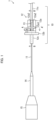
- Fig. 1 is a side view illustrating a configuration of the optical device 1.
- Fig. 2 is a cross-sectional view illustrating a section A-A' of the securing structure 10 (see Fig. 1 ).
- Fig. 3 is a cross-sectional view illustrating a section B-B' of the securing structure 10 (see Fig. 1 ).
- the optical device 1 is a device for irradiating a workpiece with laser light. As illustrated in Fig. 1 , the optical device 1 includes an optical fiber 11, a support body 12, a resin member 13, a large-diameter fiber 14, and a glass block 15. In the optical device 1, the securing structure 10 is constituted by the optical fiber 11, the support body 12, and the resin member 13. Further, the optical device 1 may include a housing (not illustrated). In this case, the housing accommodates the support body 12, the resin member 13, the large-diameter fiber 14, and the glass block 15, and the optical fiber 11 is drawn into the housing.
- the optical fiber 11 is a component for guiding laser light.
- an optical fiber including a core 11a having a circularly columnar shape, a cladding 11b having a cylindrical shape and surrounding the core 11a, and a coating 11c having a cylindrical shape and surrounding the cladding 11b is used as the optical fiber 11.
- the core 11a and the cladding 11b are made mainly of quartz.
- the coating 11c is made mainly of resin. The coating 11c is removed in a section including one end of the optical fiber 11.
- a "coating section” refers to a section where the cladding 11b is covered with the coating 11c
- a “coating-removed section” refers to a section where the coating 11c is removed and the cladding 11b is uncovered.
- the support body 12 is a component for supporting the optical fiber 11 in a linear manner.
- a support body including a flange portion 12b, a base portion 12a which is provided on one side of the flange portion 12b, and a ferrule portion 12c which is provided on the other side of the flange portion 12b is used as the support body 12.
- the support body 12 is formed in one piece of copper, and a surface of the support body 12 is plated with gold.
- the base portion 12a is a plate-like portion having a rectangular main surface. On one surface of the base portion 12a, a groove 12a1 crossing this surface lengthwise and ribs 12a2 disposed on both sides of the groove 12a1 and crossing this surface lengthwise are formed.
- the optical fiber 11 is accommodated inside the groove 12a1, and is inserted into the ferrule portion 12c via a through hole provided in a center of the flange portion 12b.
- the optical fiber 11 is disposed such that a boundary between the coating section of the optical fiber 11 and the coating-removed section of the optical fiber 11 is located inside the groove 12a1.
- the resin member 13 is a component for securing the optical fiber 11 accommodated in the groove 12a1 to the support body 12.
- a resin member obtained by curing a liquid resin that has been injected into the groove 12a1 is used as the resin member 13.
- the liquid resin may be a photo-curable resin or a heat-curable resin.
- the liquid resin is cured by the irradiation of the liquid resin with light falling within a specific wavelength band (for example, ultraviolet light).
- a specific wavelength band for example, ultraviolet light
- the liquid resin is a heat-curable resin
- the liquid resin is cured by the application of heat to the liquid resin.
- Laser light emitted from the optical fiber 11 passes through the large-diameter fiber 14 and the glass block 15 and falls on a workpiece.
- an optical fiber that has a circularly columnar shape and that is tapered down to have a decreased diameter at one end thereof is used as the large-diameter fiber 14, and a glass block that has a circularly columnar shape and that is tapered down to have a decreased diameter at one end thereof is used as the glass block 15.
- An emission end surface of the optical fiber 11 is fusion-spliced to a smaller diameter-side end surface of the large-diameter fiber 14, and a larger diameter-side end surface of the large-diameter fiber 14 is fused with a smaller diameter-side end surface of the glass block 15.
- the securing structure 10 includes the optical fiber 11, the support body 12, and the resin member 13.
- the groove 12a1 for accommodating the optical fiber 11 is formed in the support body 12.
- the resin member 13 covers a boundary between a coating section of the optical fiber 11 and a coating-removed section of the optical fiber 11 and secures the optical fiber 11 to the support body 12.
- the feature of the securing structure 10 is that the resin member 13 is spread out of the groove 12a1 partway along the groove 12a1.
- a groove 12a3 intersecting (in the present embodiment, orthogonal to) the groove 12a1 partway along the groove 12a1 is formed in the support body 12, as illustrated in Figs. 1 and 2 .
- the ribs 12a2 provided on the both sides of the groove 12a1 partly have respective missing parts partway along the groove 12a1, as illustrated in Figs. 1 and 3 .
- This allows a liquid resin injected into the groove 12a1 to go into the groove 12a3 partway along the groove 12a1 when the resin member 13 is formed.
- the resin member 13 formed by curing the liquid resin is shaped such that the resin member 13 is spread out of the groove 12a1 partway along the groove 12a1, as illustrated Figs. 1 and 2 .
- laser light with which a workpiece is to be irradiated propagates in a forward direction from an optical fiber 11 side to a glass block 15 side, and the light that has been reflected on the workpiece and the like light may propagate in a backward direction from the glass block 15 side to the optical fiber 11 side.
- part of the light propagating in the backward direction leaks, in the coating-removed section, from the cladding 11b of the optical fiber 11 into the resin member 13.
- the light that has leaked, in the coating-removed section, from the cladding 11b of the optical fiber 11 into the resin member 13 may propagate in the resin member 13 formed inside the groove 12a1 and then enter the coating 11c of the optical fiber 11 to cause the coating 11c of the optical fiber 11 to generate heat.
- the resin member 13 is spread out of the groove 12a1 partway along the groove 12a1. This causes part of the light that has leaked, in the coating-removed section, from the cladding 11b of the optical fiber 11 to the resin member 13 to be guided, before entering the coating 11c of the optical fiber 11, to the resin member 13 spread to the outside of the groove 12a1 (specifically, to the groove 12a3).
- the resin member 13 preferably has a refractive index lower than the refractive index of the cladding 11b of the optical fiber 11. This makes it possible to reduce the light that leaks, in the coating-removed section, from the cladding 11b of the optical fiber 11 to the resin member 13. Thus, it is possible to further reduce the intensity of the light entering the coating 11c of the optical fiber 11. As a result, it is possible to further reduce heat generation which may be caused in the coating 11c of the optical fiber 11 in a case where the light that has leaked, in the coating-removed section, from the cladding 11b of the optical fiber 11 to the resin member 13 enters the coating 11c of the optical fiber 11.
- the groove 12a1 is preferably a U-shaped groove as illustrated in Fig. 2 . This makes stress that the optical fiber 11 receives from the resin member 13 formed inside the groove 12a1 close to uniform (axially symmetric). As a result, it is possible to prevent degradation in beam quality which may be caused in a case where the optical fiber 11 receives nonuniform (axially asymmetric) stress.
- the groove 12a3 is preferably formed so as to be, as seen in a plan view of the support body 12, linearly symmetric with respect to the groove 12a1, as illustrated in Fig. 1 .
- a recess 12a4 for regulating the range in which the resin member 13 is spread be formed at a bottom of the groove 12a1, as illustrated in Fig. 3 . This makes it possible to prevent the resin member 13 obtained by curing the liquid resin which has been injected into the groove 12a1 at the formation of the resin member 13, overflowed from the recess 12a4, and entered the vicinity of the flange portion 12b from having an unintended shape (that results in the application of unintended stress to the optical fiber 11).
- the groove 12a1 defines a manner in which the resin member 13 spreads.
- forming the groove 12a3 intersecting the groove 12a1 allows the resin member 13 to be spread out of the groove 12a1.
- the present invention is not limited to this.
- the ribs 12a2 may define the manner in which the resin member 13 spreads. In this case, only providing the ribs 12a2 partly having missing parts partway along the groove 12a1, without forming the groove 12a3 intersecting the groove 12a1, allows the resin member 13 to be spread out of the groove 12a1.
- Fig. 4 shows the result of determination, by numerical experiment, of power of the light that, in the securing structure 10, propagates in a backward direction in the resin member 13 formed inside the groove 12a1.
- Fig. 4 is a graph, along a z-axis illustrated in Fig. 3 , showing plots of the power of the light that propagates in a backward direction in the resin member 13 formed inside the groove 12a1.
- the z-axis is parallel to a light axis of the optical fiber 11.
- the original point of the z-axis is set at a starting point of the groove 12a3. Note that, in the numerical experiment, it was assumed that the groove 12a3 had a width of 2 mm in a z-axis direction.
- the power of the light that, in the third section, propagates in a backward direction in the resin member 13 formed inside the groove 12a1 is approximately one eighth of that of the light that, in the first section, propagates in a backward direction in the resin member 13 formed inside the groove 12a1. This means that the power of light that reaches the coating 11c of the optical fiber 11 is sufficiently low.
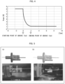
- FIG. 5 is a perspective view of a securing structure 10 (Example) and a view illustrating temperature distribution of the securing structure 10 (Example).
- (b) of Fig. 5 is a perspective view of a securing structure 10 (Comparative Example) that does not include the groove 12a3 so that the resin member 13 is not spread out of the groove 12a1 and a view illustrating temperature distribution of the securing structure 10 (Comparative Example). Both of the temperature distributions are obtained when light propagates in a backward direction in the cladding 11b of the optical fiber 11. As can be seen from the view illustrating the temperature distributions in Fig.
- Fig. 6 is a graph showing a correlation between increases in temperatures of the coatings 11c of the optical fibers 11 and deviations of the increases, with respect to the above-described Example of 5 samples and the above-described Comparative Example of 7 samples. Note that in the graph shown in Fig. 6 , the horizontal axis indicates differences between the increases in temperatures of the coatings 11c of the optical fibers 11 and the increases in temperatures of the support bodies 12, and the vertical axis indicates multiples of the standard deviations. As can be seen from the graph shown in Fig.
- the mean value of the increases in temperatures of the coatings 11c is higher by approximately 30°C than the increase in temperature of the support body 12, whereas in the Example, the mean value of the increases in temperatures of the coatings 11c is approximately equal to the increase in temperature of the support body 12. Further, as can be seen from the graph shown in Fig. 6 , in the Comparative Example, variations of the increases in temperatures of the coatings 11c are so large that an extreme increase in temperature which can cause a serious problem in the coating 11c is highly likely to occur, whereas in the Example, variations in the increases in temperatures of the coatings 11c are so small that such an extreme increase in temperature is less likely to occur. That is, it can be seen that the Example are more reliable than the Comparative Example.
- Fig. 7 is a block diagram illustrating a configuration of such a laser apparatus 20.
- the laser apparatus 20 includes a laser light source 21, a delivery fiber 22, and an optical device 23.
- the laser light source 21 is a component for generating laser light.
- the laser light source 21 may be a solid laser, a liquid laser, a gas laser, or a fiber laser.
- the delivery fiber 22 is a component for guiding the laser light generated by the laser light source 21.
- the delivery fiber 22 may be a single-mode fiber or a multimode fiber.
- the optical device 23 is a component for irradiating a workpiece W with the light guided by the delivery fiber 22.
- the above-described optical device 1 can be used as the optical device 23 to achieve a reliable laser apparatus 20.
- a securing structure in accordance with Aspect 1 of the present invention includes: an optical fiber; a support body in which a groove for accommodating the optical fiber is formed; and a resin member for covering, inside the groove, a boundary between a coating section of the optical fiber and a coating-removed section of the optical fiber and securing the optical fiber to the support body, the resin member being spread out of the groove partway along the groove.
- the above-described configuration makes light that has leaked, in the coating-removed section, from a cladding of the optical fiber to the resin member less likely to enter a coating of the optical fiber in the coating section.
- a securing structure in accordance with Aspect 2 of the present invention employs, in addition to the configuration in accordance with Aspect 1, a configuration such that another groove intersecting the groove is formed in the support body, and the resin member is spread inside the another groove.
- the above-described configuration facilitates spreading the resin member out of the groove partway along the groove in a case where the resin member is formed by curing a liquid resin that has been injected into the groove.
- a securing structure in accordance with Aspect 3 of the present invention employs, in addition to the configuration in accordance with Aspect 2, a configuration such that the another groove is formed so as to be, in a plan view of the support body, linearly symmetric with respect to the groove.
- the above-described configuration makes it possible to prevent degradation in beam quality which may be caused by nonuniform stress applied from the resin member to the optical fiber.
- a securing structure in accordance with Aspect 4 of the present invention employs, in addition to the configuration in accordance with any one of Aspects 1 to 3, a configuration such that the resin member has a refractive index lower than a refractive index of a cladding of the optical fiber.
- the above-described configuration makes it possible to further reduce heat generation caused in the coating of the optical fiber.
- a securing structure in accordance with Aspect 5 of the present invention employs, in addition to the configuration in accordance with any one of Aspects 1 to 4, a configuration such that the groove is a U-shaped groove.
- the above-described configuration makes it possible to prevent degradation in beam quality which may be caused by nonuniform stress applied from the resin member to the optical fiber.
- a securing structure in accordance with Aspect 6 of the present invention employs, in addition to the configuration in accordance with any one of Aspects 1 to 5, a configuration such that a recess for regulating a range in which the resin member is spread is formed at a bottom of the groove.
- An optical device in accordance with Aspect 7 of the present invention includes the securing structure in accordance with any one of Aspects 1 to 6.
- a laser apparatus in accordance with Aspect 8 of the present invention includes the optical device in accordance with Aspect 7.
- the above-described configuration makes it possible to achieve a more reliable laser apparatus than a laser apparatus including the conventional optical device.
- the present invention is not limited to the embodiments, but can be altered by a skilled person in the art within the scope of the claims.
- the present invention also encompasses, in its technical scope, any embodiment derived by combining technical means disclosed in differing embodiments.
Landscapes
- Physics & Mathematics (AREA)
- General Physics & Mathematics (AREA)
- Optics & Photonics (AREA)
- Mechanical Coupling Of Light Guides (AREA)
- Optical Couplings Of Light Guides (AREA)
- Light Guides In General And Applications Therefor (AREA)
- Lasers (AREA)
Abstract
Description
- The present invention relates to a securing structure for securing an optical fiber to a support body with use of a resin member. The present invention also relates to an optical device including such a securing structure and relates to a laser apparatus including such an optical device.
- A securing structure for securing an optical fiber to a support body with use of a resin member that covers a boundary between a coating-removed section of an optical fiber and a coating section of the optical fiber is widely used. For example,
Patent Literature 1 discloses a securing structure for securing an optical fiber to an end portion (equivalent to the above-described support body) with use of a guiding adhesive (equivalent to the above-described resin member) that covers a boundary between a coating-removed section of an optical fiber and a coating section of the optical fiber. Note that the coating section refers to a section where a cladding of the optical fiber is covered with a coating, and the coating-removed section refers to a section where the coating of the cladding is removed and the cladding is uncovered. - [Patent Literature 1]
Published Japanese Translation ofPCT International Application Tokuhyo No. 2016-533543 - However, in the conventional securing structure, the light that has leaked, in the coating-removed section, from the cladding of the optical fiber to the resin member may enter the coating in the coating section and cause the coating to generate heat. This may cause a decrease in reliability of the securing structure.
- An aspect of the present invention has been made in view of the foregoing problems. It is an object of the aspect of the present invention to achieve a reliable securing structure that reduces heat generation which may be caused in a coating in a case where light that has leaked, in the coating-removed section, from the cladding of the optical fiber to the resin member enters the coating in the coating section. It is an object of another aspect of the present invention to achieve a reliable optical device with use of such a securing structure. It is an object of still another aspect of the present invention to achieve a reliable laser apparatus with use of such an optical device.
- A securing structure in accordance with an aspect of the present invention includes: an optical fiber; a support body in which a groove for accommodating the optical fiber is formed; and a resin member for covering, inside the groove, a boundary between a coating section of the optical fiber and a coating-removed section of the optical fiber and securing the optical fiber to the support body, the resin member being spread out of the groove partway along the groove.
- An optical device in accordance with an aspect of the present invention includes a securing structure in accordance with an aspect of the present invention.
- A laser apparatus in accordance with an aspect of the present invention includes an optical device in accordance with an aspect of the present invention.
- An aspect of the present invention makes it possible to achieve a reliable securing structure that reduces heat generation which may be caused in a coating in a case where light that has leaked, in the coating-removed section, from the cladding of the optical fiber to the resin member enters the coating in the coating section. Another aspect of the present invention makes it possible to achieve a reliable optical device with use of such a securing structure. Still another aspect of the present invention makes it possible to achieve a reliable laser apparatus with use of such an optical device.
-
-
Fig. 1 is a side view illustrating a configuration of an optical device including a securing structure in accordance with an embodiment of the present invention. -
Fig. 2 is a cross-sectional view illustrating a section A-A' of the optical device illustrated inFig. 1 . -
Fig. 3 is a cross-sectional view illustrating a section B-B' of the optical device illustrated inFig. 1 . -
Fig. 4 is a graph showing a measurement result of power of light that propagates in a backward direction inside a groove in the securing structure illustrated inFigs. 1 to 3 .
(a) ofFig. 5 is a perspective view of a securing structure in accordance with Example and a view illustrating temperature distribution of the securing structure in accordance with the Example. (b) ofFig. 5 is a perspective view of a securing structure in accordance with Comparative Example and a view illustrating temperature distribution of the securing structure in accordance with the Comparative Example. -
Fig. 6 is a graph showing a correlation between increases in temperatures of coatings of optical fibers and deviations of the increases, with respect to Example of 5 samples and Comparative Example of 7 samples. -
Fig. 7 is a block diagram of a laser apparatus including the optical device illustrated inFig. 1 . - The following will describe an
optical device 1 including asecuring structure 10 in accordance with an embodiment of the present invention with reference toFigs. 1 to 3 .Fig. 1 is a side view illustrating a configuration of theoptical device 1.Fig. 2 is a cross-sectional view illustrating a section A-A' of the securing structure 10 (seeFig. 1 ).Fig. 3 is a cross-sectional view illustrating a section B-B' of the securing structure 10 (seeFig. 1 ). - The
optical device 1 is a device for irradiating a workpiece with laser light. As illustrated inFig. 1 , theoptical device 1 includes anoptical fiber 11, asupport body 12, aresin member 13, a large-diameter fiber 14, and aglass block 15. In theoptical device 1, thesecuring structure 10 is constituted by theoptical fiber 11, thesupport body 12, and theresin member 13. Further, theoptical device 1 may include a housing (not illustrated). In this case, the housing accommodates thesupport body 12, theresin member 13, the large-diameter fiber 14, and theglass block 15, and theoptical fiber 11 is drawn into the housing. - The
optical fiber 11 is a component for guiding laser light. In the present embodiment, an optical fiber including acore 11a having a circularly columnar shape, a cladding 11b having a cylindrical shape and surrounding thecore 11a, and acoating 11c having a cylindrical shape and surrounding thecladding 11b is used as theoptical fiber 11. Thecore 11a and the cladding 11b are made mainly of quartz. Thecoating 11c is made mainly of resin. Thecoating 11c is removed in a section including one end of theoptical fiber 11. In theoptical fiber 11, a "coating section" refers to a section where thecladding 11b is covered with thecoating 11c, and a "coating-removed section" refers to a section where thecoating 11c is removed and thecladding 11b is uncovered. - The
support body 12 is a component for supporting theoptical fiber 11 in a linear manner. In the present embodiment, a support body including aflange portion 12b, abase portion 12a which is provided on one side of theflange portion 12b, and aferrule portion 12c which is provided on the other side of theflange portion 12b is used as thesupport body 12. Thesupport body 12 is formed in one piece of copper, and a surface of thesupport body 12 is plated with gold. Thebase portion 12a is a plate-like portion having a rectangular main surface. On one surface of thebase portion 12a, a groove 12a1 crossing this surface lengthwise and ribs 12a2 disposed on both sides of the groove 12a1 and crossing this surface lengthwise are formed. Theoptical fiber 11 is accommodated inside the groove 12a1, and is inserted into theferrule portion 12c via a through hole provided in a center of theflange portion 12b. In this case, theoptical fiber 11 is disposed such that a boundary between the coating section of theoptical fiber 11 and the coating-removed section of theoptical fiber 11 is located inside the groove 12a1. - The
resin member 13 is a component for securing theoptical fiber 11 accommodated in the groove 12a1 to thesupport body 12. In the present embodiment, a resin member obtained by curing a liquid resin that has been injected into the groove 12a1 is used as theresin member 13. The liquid resin may be a photo-curable resin or a heat-curable resin. In a case where the liquid resin is a photo-curable resin, the liquid resin is cured by the irradiation of the liquid resin with light falling within a specific wavelength band (for example, ultraviolet light). In a case where the liquid resin is a heat-curable resin, the liquid resin is cured by the application of heat to the liquid resin. - Laser light emitted from the
optical fiber 11 passes through the large-diameter fiber 14 and theglass block 15 and falls on a workpiece. In the present embodiment, an optical fiber that has a circularly columnar shape and that is tapered down to have a decreased diameter at one end thereof is used as the large-diameter fiber 14, and a glass block that has a circularly columnar shape and that is tapered down to have a decreased diameter at one end thereof is used as theglass block 15. An emission end surface of theoptical fiber 11 is fusion-spliced to a smaller diameter-side end surface of the large-diameter fiber 14, and a larger diameter-side end surface of the large-diameter fiber 14 is fused with a smaller diameter-side end surface of theglass block 15. - In the
optical device 1, the securingstructure 10 includes theoptical fiber 11, thesupport body 12, and theresin member 13. As illustrated inFigs. 1 and3 , the groove 12a1 for accommodating theoptical fiber 11 is formed in thesupport body 12. As illustrated inFigs. 1 and3 , inside the groove 12a1, theresin member 13 covers a boundary between a coating section of theoptical fiber 11 and a coating-removed section of theoptical fiber 11 and secures theoptical fiber 11 to thesupport body 12. - The feature of the securing
structure 10 is that theresin member 13 is spread out of the groove 12a1 partway along the groove 12a1. In order to achieve the feature, in the securingstructure 10 in accordance with the present embodiment, a groove 12a3 intersecting (in the present embodiment, orthogonal to) the groove 12a1 partway along the groove 12a1 is formed in thesupport body 12, as illustrated inFigs. 1 and2 . The ribs 12a2 provided on the both sides of the groove 12a1 partly have respective missing parts partway along the groove 12a1, as illustrated inFigs. 1 and3 . This allows a liquid resin injected into the groove 12a1 to go into the groove 12a3 partway along the groove 12a1 when theresin member 13 is formed. Thus, theresin member 13 formed by curing the liquid resin is shaped such that theresin member 13 is spread out of the groove 12a1 partway along the groove 12a1, as illustratedFigs. 1 and2 . - When processing is performed with use of the
optical device 1, laser light with which a workpiece is to be irradiated propagates in a forward direction from anoptical fiber 11 side to aglass block 15 side, and the light that has been reflected on the workpiece and the like light may propagate in a backward direction from theglass block 15 side to theoptical fiber 11 side. In this case, part of the light propagating in the backward direction leaks, in the coating-removed section, from thecladding 11b of theoptical fiber 11 into theresin member 13. The light that has leaked, in the coating-removed section, from thecladding 11b of theoptical fiber 11 into theresin member 13 may propagate in theresin member 13 formed inside the groove 12a1 and then enter thecoating 11c of theoptical fiber 11 to cause thecoating 11c of theoptical fiber 11 to generate heat. In contrast, in the securingstructure 10, theresin member 13 is spread out of the groove 12a1 partway along the groove 12a1. This causes part of the light that has leaked, in the coating-removed section, from thecladding 11b of theoptical fiber 11 to theresin member 13 to be guided, before entering thecoating 11c of theoptical fiber 11, to theresin member 13 spread to the outside of the groove 12a1 (specifically, to the groove 12a3). Thus, it is possible to minimize the ratio of the light that enters thecoating 11c of theoptical fiber 11 in the light that has leaked, in the coating-removed section, from thecladding 11b of theoptical fiber 11 to theresin member 13. As a result, it is possible to reduce heat generation which may be caused in thecoating 11c of theoptical fiber 11 in a case where the light that has leaked, in the coating-removed section, from thecladding 11b of theoptical fiber 11 to theresin member 13 enters thecoating 11c of theoptical fiber 11. Therefore, it is possible to achieve thereliable securing structure 10. As a result, it is possible to achieve the reliableoptical device 1. - The
resin member 13 preferably has a refractive index lower than the refractive index of thecladding 11b of theoptical fiber 11. This makes it possible to reduce the light that leaks, in the coating-removed section, from thecladding 11b of theoptical fiber 11 to theresin member 13. Thus, it is possible to further reduce the intensity of the light entering thecoating 11c of theoptical fiber 11. As a result, it is possible to further reduce heat generation which may be caused in thecoating 11c of theoptical fiber 11 in a case where the light that has leaked, in the coating-removed section, from thecladding 11b of theoptical fiber 11 to theresin member 13 enters thecoating 11c of theoptical fiber 11. - Further, the groove 12a1 is preferably a U-shaped groove as illustrated in
Fig. 2 . This makes stress that theoptical fiber 11 receives from theresin member 13 formed inside the groove 12a1 close to uniform (axially symmetric). As a result, it is possible to prevent degradation in beam quality which may be caused in a case where theoptical fiber 11 receives nonuniform (axially asymmetric) stress. - Further, the groove 12a3 is preferably formed so as to be, as seen in a plan view of the
support body 12, linearly symmetric with respect to the groove 12a1, as illustrated inFig. 1 . This makes the stress that theoptical fiber 11 receives from theresin member 13 formed inside the grooves 12a1 and 12a3 close to uniform (linearly symmetric). As a result, it is possible to prevent degradation in beam quality which may be caused in a case where theoptical fiber 11 receives nonuniform (linearly asymmetric) stress. - Further, it is preferable that a recess 12a4 for regulating the range in which the
resin member 13 is spread be formed at a bottom of the groove 12a1, as illustrated inFig. 3 . This makes it possible to prevent theresin member 13 obtained by curing the liquid resin which has been injected into the groove 12a1 at the formation of theresin member 13, overflowed from the recess 12a4, and entered the vicinity of theflange portion 12b from having an unintended shape (that results in the application of unintended stress to the optical fiber 11). - In the present embodiment, the groove 12a1 defines a manner in which the
resin member 13 spreads. Thus, forming the groove 12a3 intersecting the groove 12a1 allows theresin member 13 to be spread out of the groove 12a1. However, the present invention is not limited to this. For example, the ribs 12a2 may define the manner in which theresin member 13 spreads. In this case, only providing the ribs 12a2 partly having missing parts partway along the groove 12a1, without forming the groove 12a3 intersecting the groove 12a1, allows theresin member 13 to be spread out of the groove 12a1. -
Fig. 4 shows the result of determination, by numerical experiment, of power of the light that, in the securingstructure 10, propagates in a backward direction in theresin member 13 formed inside the groove 12a1.Fig. 4 is a graph, along a z-axis illustrated inFig. 3 , showing plots of the power of the light that propagates in a backward direction in theresin member 13 formed inside the groove 12a1. Here, the z-axis is parallel to a light axis of theoptical fiber 11. The original point of the z-axis is set at a starting point of the groove 12a3. Note that, in the numerical experiment, it was assumed that the groove 12a3 had a width of 2 mm in a z-axis direction. Note that it was assumed that a refractive index of thecladding 11b of theoptical fiber 11 was 1.45, a refractive index of the air was 1, and a refractive index of theresin member 13 was 1.41. In addition, it was assumed that in the section from z=-2 to z=0, theresin member 13 filled in the groove 12a1 with no gap, and in the section from z=0 to z=2, theresin member 13 filled in the grooves 12a1 and 12a3 with no gap. - The graph shown in
Fig. 4 reveals the following: in a first section from z=-2 to z=0 in which theresin member 13 is formed only inside the groove 12a1, the power of the light that propagates in a backward direction in theresin member 13 formed inside the groove 12a1 keeps substantially constant; in a second section from z=0 to z=2 in which theresin member 13 is spread out of the groove 12a1, the power of the light that propagates in a backward direction in theresin member 13 formed inside the groove 12a1 is decreased rapidly; and in a third section of z= a value of not less than 2 in which theresin member 13 is formed only inside the groove 12a1, the power of the light that propagates in a backward direction in theresin member 13 formed inside the groove 12a1 keeps substantially constant. The power of the light that, in the third section, propagates in a backward direction in theresin member 13 formed inside the groove 12a1 is approximately one eighth of that of the light that, in the first section, propagates in a backward direction in theresin member 13 formed inside the groove 12a1. This means that the power of light that reaches thecoating 11c of theoptical fiber 11 is sufficiently low. - (a) of
Fig. 5 is a perspective view of a securing structure 10 (Example) and a view illustrating temperature distribution of the securing structure 10 (Example). (b) ofFig. 5 is a perspective view of a securing structure 10 (Comparative Example) that does not include the groove 12a3 so that theresin member 13 is not spread out of the groove 12a1 and a view illustrating temperature distribution of the securing structure 10 (Comparative Example). Both of the temperature distributions are obtained when light propagates in a backward direction in thecladding 11b of theoptical fiber 11. As can be seen from the view illustrating the temperature distributions inFig. 5 , in the Comparative Example in which theresin member 13 is not spread out of the groove 12a1, the temperature of thecoating 11c of theoptical fiber 11 reaches approximately 100°C, whereas in the Example in which theresin member 13 is spread out of the groove 12a1, the temperature of thecoating 11c of theoptical fiber 11 is suppressed to approximately 40°C. That is, it was confirmed that providing the groove 12a3 and spreading theresin member 13 out of the groove 12a1 could reduce heat generation which was caused in thecoating 11c of theoptical fiber 11 by the light that had leaked, in the coating-removed section, from thecladding 11b of theoptical fiber 11 to theresin member 13. -
Fig. 6 is a graph showing a correlation between increases in temperatures of thecoatings 11c of theoptical fibers 11 and deviations of the increases, with respect to the above-described Example of 5 samples and the above-described Comparative Example of 7 samples. Note that in the graph shown inFig. 6 , the horizontal axis indicates differences between the increases in temperatures of thecoatings 11c of theoptical fibers 11 and the increases in temperatures of thesupport bodies 12, and the vertical axis indicates multiples of the standard deviations. As can be seen from the graph shown inFig. 6 , in the Comparative Example, the mean value of the increases in temperatures of thecoatings 11c is higher by approximately 30°C than the increase in temperature of thesupport body 12, whereas in the Example, the mean value of the increases in temperatures of thecoatings 11c is approximately equal to the increase in temperature of thesupport body 12. Further, as can be seen from the graph shown inFig. 6 , in the Comparative Example, variations of the increases in temperatures of thecoatings 11c are so large that an extreme increase in temperature which can cause a serious problem in thecoating 11c is highly likely to occur, whereas in the Example, variations in the increases in temperatures of thecoatings 11c are so small that such an extreme increase in temperature is less likely to occur. That is, it can be seen that the Example are more reliable than the Comparative Example. - The above-described
optical device 1 can be used in a laser apparatus for processing.Fig. 7 is a block diagram illustrating a configuration of such alaser apparatus 20. - The
laser apparatus 20 includes alaser light source 21, adelivery fiber 22, and anoptical device 23. Thelaser light source 21 is a component for generating laser light. Thelaser light source 21 may be a solid laser, a liquid laser, a gas laser, or a fiber laser. Thedelivery fiber 22 is a component for guiding the laser light generated by thelaser light source 21. Thedelivery fiber 22 may be a single-mode fiber or a multimode fiber. Theoptical device 23 is a component for irradiating a workpiece W with the light guided by thedelivery fiber 22. The above-describedoptical device 1 can be used as theoptical device 23 to achieve areliable laser apparatus 20. - Aspects of the present invention can also be expressed as follows:
As described above, a securing structure in accordance withAspect 1 of the present invention includes: an optical fiber; a support body in which a groove for accommodating the optical fiber is formed; and a resin member for covering, inside the groove, a boundary between a coating section of the optical fiber and a coating-removed section of the optical fiber and securing the optical fiber to the support body, the resin member being spread out of the groove partway along the groove. - The above-described configuration makes light that has leaked, in the coating-removed section, from a cladding of the optical fiber to the resin member less likely to enter a coating of the optical fiber in the coating section. Thus, it is possible to reduce heat generation caused in the coating of the optical fiber as compared with a case where the resin member is formed only inside the groove. As a result, it is possible to achieve a reliable securing structure as compared with the case where the resin member is formed only inside the groove.
- A securing structure in accordance with
Aspect 2 of the present invention employs, in addition to the configuration in accordance withAspect 1, a configuration such that another groove intersecting the groove is formed in the support body, and the resin member is spread inside the another groove. - The above-described configuration facilitates spreading the resin member out of the groove partway along the groove in a case where the resin member is formed by curing a liquid resin that has been injected into the groove.
- A securing structure in accordance with
Aspect 3 of the present invention employs, in addition to the configuration in accordance withAspect 2, a configuration such that the another groove is formed so as to be, in a plan view of the support body, linearly symmetric with respect to the groove. - The above-described configuration makes it possible to prevent degradation in beam quality which may be caused by nonuniform stress applied from the resin member to the optical fiber.
- A securing structure in accordance with
Aspect 4 of the present invention employs, in addition to the configuration in accordance with any one ofAspects 1 to 3, a configuration such that the resin member has a refractive index lower than a refractive index of a cladding of the optical fiber. - The above-described configuration makes it possible to further reduce heat generation caused in the coating of the optical fiber.
- A securing structure in accordance with Aspect 5 of the present invention employs, in addition to the configuration in accordance with any one of
Aspects 1 to 4, a configuration such that the groove is a U-shaped groove. - The above-described configuration makes it possible to prevent degradation in beam quality which may be caused by nonuniform stress applied from the resin member to the optical fiber.
- A securing structure in accordance with
Aspect 6 of the present invention employs, in addition to the configuration in accordance with any one ofAspects 1 to 5, a configuration such that a recess for regulating a range in which the resin member is spread is formed at a bottom of the groove. - The above-described configuration makes less likely to occur a situation where a resin member having an unintended shape is formed, and, as a result, unintended stress acts on the optical fiber.
- An optical device in accordance with
Aspect 7 of the present invention includes the securing structure in accordance with any one ofAspects 1 to 6. - The above-described configuration makes it possible to achieve a more reliable optical device than an optical device including the conventional securing structure.
- A laser apparatus in accordance with
Aspect 8 of the present invention includes the optical device in accordance withAspect 7. - The above-described configuration makes it possible to achieve a more reliable laser apparatus than a laser apparatus including the conventional optical device.
- The present invention is not limited to the embodiments, but can be altered by a skilled person in the art within the scope of the claims. The present invention also encompasses, in its technical scope, any embodiment derived by combining technical means disclosed in differing embodiments.
-
- 1
- Optical device
- 10
- Securing structure
- 11
- Optical fiber
- 11a
- Core
- 11b
- Cladding
- 11c
- Coating
- 12
- Support body
- 12a
- Base portion
- 12a1
- Groove
- 12a2
- Rib
- 12a3
- groove
- 12a4
- Recess
- 13
- Resin member
- 14
- Large-diameter fiber
- 15
- Glass block
- 20
- Laser apparatus
- 21
- Laser light source
- 22
- Delivery fiber
- 23
- Optical device
Claims (8)
- A securing structure comprising:an optical fiber;a support body in which a groove for accommodating the optical fiber is formed; anda resin member for covering, inside the groove, a boundary between a coating section of the optical fiber and a coating-removed section of the optical fiber and securing the optical fiber to the support body,the resin member being spread out of the groove partway along the groove.
- The securing structure according to claim 1, whereinanother groove intersecting the groove is formed in the support body; andthe resin member is spread inside the another groove.
- The securing structure according to claim 2, wherein
the another groove is formed so as to be, in a plan view of the support body, linearly symmetric with respect to the groove. - The securing structure according to any one of claims 1 to 3, wherein
the resin member has a refractive index lower than a refractive index of a cladding of the optical fiber. - The securing structure according to any one of claims 1 to 4, wherein
the groove is a U-shaped groove. - The securing structure according to any one of claims 1 to 5, wherein
a recess for regulating a range in which the resin member is spread is formed at a bottom of the groove. - An optical device comprising the securing structure according to any one of claims 1 to 6.
- A laser apparatus comprising the optical device according to claim 7.
Applications Claiming Priority (2)
| Application Number | Priority Date | Filing Date | Title |
|---|---|---|---|
| JP2020114282 | 2020-07-01 | ||
| PCT/JP2021/018038 WO2022004141A1 (en) | 2020-07-01 | 2021-05-12 | Securing structure, optical device, and laser apparatus |
Publications (2)
| Publication Number | Publication Date |
|---|---|
| EP4177648A1 true EP4177648A1 (en) | 2023-05-10 |
| EP4177648A4 EP4177648A4 (en) | 2024-08-14 |
Family
ID=79315211
Family Applications (1)
| Application Number | Title | Priority Date | Filing Date |
|---|---|---|---|
| EP21832252.7A Pending EP4177648A4 (en) | 2020-07-01 | 2021-05-12 | MOUNTING STRUCTURE, OPTICAL DEVICE AND LASER DEVICE |
Country Status (5)
| Country | Link |
|---|---|
| US (1) | US20230204864A1 (en) |
| EP (1) | EP4177648A4 (en) |
| JP (1) | JP7489464B2 (en) |
| CN (1) | CN115668024A (en) |
| WO (1) | WO2022004141A1 (en) |
Family Cites Families (19)
| Publication number | Priority date | Publication date | Assignee | Title |
|---|---|---|---|---|
| JP2888441B2 (en) * | 1989-09-30 | 1999-05-10 | 株式会社フジクラ | Optical device manufacturing method |
| US5076654A (en) * | 1990-10-29 | 1991-12-31 | At&T Bell Laboratories | Packaging of silicon optical components |
| JP2787122B2 (en) * | 1991-07-05 | 1998-08-13 | 日本航空電子工業株式会社 | Fixing structure of optical fiber to carrier |
| US5151964A (en) * | 1991-09-06 | 1992-09-29 | Minnesota Mining And Manufacturing Company | Wedge-actuated multiple optical fiber splice |
| JP3136741B2 (en) * | 1992-02-07 | 2001-02-19 | 住友電気工業株式会社 | Optical fiber reinforcement method |
| JPH08286073A (en) * | 1995-04-18 | 1996-11-01 | Sumitomo Electric Ind Ltd | Package structure for mounting optical waveguide |
| JPH1020146A (en) * | 1996-07-03 | 1998-01-23 | Takaoka Electric Mfg Co Ltd | Coupling structure and coupling method between optical waveguide and optical fiber |
| JPH11109188A (en) * | 1997-10-03 | 1999-04-23 | Hitachi Ltd | Substrate for mounting semiconductor elements and optical fibers |
| FR2797058A1 (en) * | 1999-07-29 | 2001-02-02 | Kyocera Corp | Fiber-hob system used in optic communication system includes end piece, through which optic fibers are inserted, groove, and optocoupler, placed in groove |
| JP2005202164A (en) * | 2004-01-15 | 2005-07-28 | Omron Corp | Optical fiber holding member and manufacturing method thereof |
| US7349596B2 (en) * | 2006-03-16 | 2008-03-25 | Northrop Grumman Corporation | System and method to remove light from cladding |
| JP4776420B2 (en) * | 2006-03-30 | 2011-09-21 | 古河電気工業株式会社 | Optical fiber protector |
| DE102008011525A1 (en) * | 2008-02-27 | 2009-09-10 | Jenoptik Laserdiode Gmbh | Method for producing a light transmission arrangement and light transmission arrangement |
| WO2009155707A1 (en) * | 2008-06-25 | 2009-12-30 | Coractive High-Tech Inc. | Energy dissipating packages for high power operation of optical fiber components |
| WO2014110037A1 (en) * | 2013-01-08 | 2014-07-17 | Commscope, Inc. Of North Carolina | Selective uv curing of epoxy adjacent to optical fibers by transmitting uv energy through the fiber cladding |
| JP2016513874A (en) * | 2013-03-06 | 2016-05-16 | アイピージー フォトニクス コーポレーション | Ultra-high power single mode fiber laser system with non-uniformly configured fiber-fiber rod multimode amplifier |
| US9285542B2 (en) * | 2014-07-09 | 2016-03-15 | International Business Machines Corporation | Fiber optic interface with adhesive fill system |
| JP6623240B2 (en) * | 2018-02-20 | 2019-12-18 | 株式会社フジクラ | Clad mode stripper and laser apparatus |
| JP7521458B2 (en) * | 2021-03-04 | 2024-07-24 | 住友電気工業株式会社 | Optical Connector Cable |
-
2021
- 2021-05-12 CN CN202180037392.7A patent/CN115668024A/en active Pending
- 2021-05-12 WO PCT/JP2021/018038 patent/WO2022004141A1/en not_active Ceased
- 2021-05-12 JP JP2022533711A patent/JP7489464B2/en active Active
- 2021-05-12 EP EP21832252.7A patent/EP4177648A4/en active Pending
- 2021-05-12 US US18/008,242 patent/US20230204864A1/en active Pending
Also Published As
| Publication number | Publication date |
|---|---|
| CN115668024A (en) | 2023-01-31 |
| WO2022004141A1 (en) | 2022-01-06 |
| EP4177648A4 (en) | 2024-08-14 |
| JPWO2022004141A1 (en) | 2022-01-06 |
| JP7489464B2 (en) | 2024-05-23 |
| US20230204864A1 (en) | 2023-06-29 |
Similar Documents
| Publication | Publication Date | Title |
|---|---|---|
| JP5147834B2 (en) | Laser processing apparatus and laser processing method | |
| US7474822B2 (en) | Optical fiber collimator | |
| US20210373348A1 (en) | Splice with cladding mode light stripping | |
| US20200132943A1 (en) | Methods for processing ferrules and/or optical fibers | |
| US6069988A (en) | Optical fiber and its manufacturing method | |
| JP6122785B2 (en) | Manufacturing method of optical fiber side input / output device | |
| JP6170527B2 (en) | Optical receptacle and optical transceiver | |
| US20110135260A1 (en) | Optical fiber | |
| CN102257416A (en) | Spliced connection between two optical fibres and method for producing a spliced connection of this type | |
| CN104521077A (en) | High power spatial filter | |
| JP6656076B2 (en) | Fiber structure and light source device | |
| EP4177648A1 (en) | Securing structure, optical device, and laser apparatus | |
| JPH11284255A (en) | Fiber laser device and laser machining device | |
| US10833470B2 (en) | Optical fiber and fiber laser | |
| US9690055B2 (en) | Laser-based systems and methods for fiber-to-ferrule bonding for optical fiber connectors | |
| EP3525018B1 (en) | Optical fiber and fiber laser | |
| JP5342343B2 (en) | Method for assembling ferrule for optical connector, assembly jig, and ferrule structure for optical connector | |
| JP2004177937A (en) | Ferrule and optical coupling structure | |
| US20130230282A1 (en) | Light guiding device and light guiding method | |
| CN101661139A (en) | Optical sub-assembly with glass member physically contact with external fiber | |
| JP4302373B2 (en) | Light guide device | |
| US8348520B2 (en) | Optical connector structure | |
| US10466426B2 (en) | Optical fiber drawer structure and optical module | |
| CN113169508B (en) | Laser device and method for manufacturing laser device | |
| EP2824491B1 (en) | Optical connector |
Legal Events
| Date | Code | Title | Description |
|---|---|---|---|
| STAA | Information on the status of an ep patent application or granted ep patent |
Free format text: STATUS: THE INTERNATIONAL PUBLICATION HAS BEEN MADE |
|
| PUAI | Public reference made under article 153(3) epc to a published international application that has entered the european phase |
Free format text: ORIGINAL CODE: 0009012 |
|
| STAA | Information on the status of an ep patent application or granted ep patent |
Free format text: STATUS: REQUEST FOR EXAMINATION WAS MADE |
|
| 17P | Request for examination filed |
Effective date: 20221122 |
|
| AK | Designated contracting states |
Kind code of ref document: A1 Designated state(s): AL AT BE BG CH CY CZ DE DK EE ES FI FR GB GR HR HU IE IS IT LI LT LU LV MC MK MT NL NO PL PT RO RS SE SI SK SM TR |
|
| DAV | Request for validation of the european patent (deleted) | ||
| DAX | Request for extension of the european patent (deleted) | ||
| A4 | Supplementary search report drawn up and despatched |
Effective date: 20240715 |
|
| RIC1 | Information provided on ipc code assigned before grant |
Ipc: G02B 6/36 20060101ALI20240710BHEP Ipc: H01S 3/10 20060101ALI20240710BHEP Ipc: G02B 6/46 20060101ALI20240710BHEP Ipc: G02B 6/02 20060101AFI20240710BHEP |