EP4177554A1 - A cooling device - Google Patents
A cooling device Download PDFInfo
- Publication number
- EP4177554A1 EP4177554A1 EP22198935.3A EP22198935A EP4177554A1 EP 4177554 A1 EP4177554 A1 EP 4177554A1 EP 22198935 A EP22198935 A EP 22198935A EP 4177554 A1 EP4177554 A1 EP 4177554A1
- Authority
- EP
- European Patent Office
- Prior art keywords
- protrusion
- board casing
- cooling device
- board
- casing
- Prior art date
- Legal status (The legal status is an assumption and is not a legal conclusion. Google has not performed a legal analysis and makes no representation as to the accuracy of the status listed.)
- Granted
Links
Images
Classifications
-
- F—MECHANICAL ENGINEERING; LIGHTING; HEATING; WEAPONS; BLASTING
- F25—REFRIGERATION OR COOLING; COMBINED HEATING AND REFRIGERATION SYSTEMS; HEAT PUMP SYSTEMS; MANUFACTURE OR STORAGE OF ICE; LIQUEFACTION SOLIDIFICATION OF GASES
- F25D—REFRIGERATORS; COLD ROOMS; ICE-BOXES; COOLING OR FREEZING APPARATUS NOT OTHERWISE PROVIDED FOR
- F25D23/00—General constructional features
- F25D23/06—Walls
- F25D23/062—Walls defining a cabinet
- F25D23/064—Walls defining a cabinet formed by moulding, e.g. moulding in situ
-
- F—MECHANICAL ENGINEERING; LIGHTING; HEATING; WEAPONS; BLASTING
- F25—REFRIGERATION OR COOLING; COMBINED HEATING AND REFRIGERATION SYSTEMS; HEAT PUMP SYSTEMS; MANUFACTURE OR STORAGE OF ICE; LIQUEFACTION SOLIDIFICATION OF GASES
- F25D—REFRIGERATORS; COLD ROOMS; ICE-BOXES; COOLING OR FREEZING APPARATUS NOT OTHERWISE PROVIDED FOR
- F25D2201/00—Insulation
- F25D2201/10—Insulation with respect to heat
- F25D2201/12—Insulation with respect to heat using an insulating packing material
- F25D2201/126—Insulation with respect to heat using an insulating packing material of cellular type
Definitions
- the present invention relates to a cooling device wherein the board casing is prevented from being deformed.
- cooling devices especially in refrigerators and freezers, polyurethane-based insulation material is usually filled between the inner wall and the outer wall of the body in order to provide thermal insulation between the inner volume of the body and the external environment.
- the cooling device also comprises a door to close and seal the body which is the storage volume.
- the cooling device may be formed as a growth chamber, an ice box, a refrigerator, a freezer, a refrigerator-freezer combination and/or a wine cooler.
- the inner wall and the outer wall of the body are placed in a mold and an insulation material such as polyurethane is injected between the inner wall and the outer wall in liquid form while inside the mold, and then the polyurethane expands after a while due to its properties, filling the insulation volume between the inner wall and the outer wall. Due to the method used to fill the insulation volume with insulation material, the insulation material does not spread homogeneously inside the insulation volume. In particular, if the body is removed from the mold without waiting for the curing and cooling of the insulation material, the insulation material continues to cool down.
- an insulation material such as polyurethane
- the board casing which is located in the cooling device as embedded in the insulation volume and which protects the circuit board, is also deformed during the polyurethane injection process due to the reasons mentioned above.
- said structural defects which occur in the board casing due to the polyurethane injection process are solved by placing various support members between the board casing walls. This process both increases the cost and requires additional labor.
- a cooling device wherein the deformation of the casing during the polyurethane process is prevented by means of a protrusion provided on the board casing.
- the protrusion is a protrusion which passes through the circuit board placed into the casing.
- a household appliance especially a cooling device, comprising additional support members manufactured from various materials in various forms so as to increase the strength of the board casing during the injection of the insulation material.
- the aim of the present invention is the realization of a cooling device comprising a board casing of which the strength is increased against the pressure exerted by the insulation material during the application of the insulation material.
- the cooling device realized in order to attain the aim of the present invention, explicated in the first claim and the respective claims thereof, comprises a body having an inner wall and an outer wall and an insulation volume remaining therebetween; a board casing which is disposed in the insulation volume; and at least one protrusion which increases the strength of the board casing during the application of the insulation material into the insulation volume and which is broken afterwards to be removed from inside the board casing.
- This temporary arrangement of the protrusions eliminates the need to make any design changes to the board casing or the boards to be placed into the board casing.
- the board casing is preferably a casing which receives circuit boards, or can be a casing which receives other physical components.
- the protrusion extends from the base of the board casing to the ceiling of the board casing in the vertical axis.
- the protrusion comprises at least one recess which is arranged thereon, which allows the protrusion to be broken and removed from inside the board casing after the application of the insulation material is completed, which extends parallel to the base along the protrusion, which weakens the protrusion and which causes the notch effect.
- the recess extends continuously parallel to the base.
- the recess extends along the protrusion, parallel to the base, intermittently, at intervals.
- the recess is arranged on the protrusion, at the bottom of the protrusion, that is, closest to the base of the board casing.
- the cross-section of the recess is triangular or circular. Thus, it is ensured that the protrusion is broken smoothly along a certain cross-section. In addition, it is ensured that the remaining part does not harm the operator.
- the protrusions extending from the base of the board casing thanks to the protrusions extending from the base of the board casing, during the application of the insulation material, the strength of the board casing is increased and it has been ensured that the walls of the board casing are prevented from being deformed, and moreover, after the application of the insulation material is completed, the protrusions are broken and removed from inside the board casing such that the desired circuit board is easily placed into the board casing, regardless of the dimensions of the circuit board to be placed in the board casing.
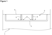
- Figure 1 - is the sideways cross-sectional view of a body and the board casing therein.
- the cooling device comprises a body (1) having an inner wall and an outer wall and an insulation volume remaining therebetween; a board casing (2) which is disposed in the insulation volume; and at least one protrusion (5) which increases the strength of the board casing (2) during the filling of the insulation material into the insulation volume and which is broken afterwards to be removed from inside the board casing (2).
- the deformation of the walls of the board casing (2) is prevented during the production of the cooling device and the filling of the insulation material, and after the application of the insulation material is completed, the protrusion (5) is broken by the operator and removed from inside the board casing (2) such that the circuit board can be easily mounted into the board casing (2) without any limitations arising due to the protrusion (5).
- the protrusion (5) extends from the base (3) of the board casing (2) to the ceiling (4) of the board casing (2) in the vertical axis.
- the protrusion (5) comprises at least one recess (6) which is arranged thereon, which allows the protrusion (5) to be broken and removed from inside the board casing (2) after the filling of the insulation material is completed, which extends parallel to the base (3) along the protrusion (5) and which weakens the protrusion (5).
- a break line (F) is formed, thus enabling the operator to break the protrusion (5) easily and quickly.
- the recess (6) extends on the protrusion (5) continuously parallel to the base (3).
- the recess (6) extends on the protrusion (5), parallel to the base (3), intermittently, at intervals.
- the recess (6) is arranged on the protrusion (5), at the bottom of the protrusion (5), that is, closest to the base (3) of the board casing (2).
- the cross-section of the recess (6) is triangular.
- the cross-section of the recess (6) is curved, preferably semicircular.
- the protrusions (5) extend from the base of the board casing (2) towards the ceiling (4) thereof. During the application of the insulation material, said protrusions (5) support the walls of the board casing (2) and increase the strength of the board casing (2) during the application of the insulation material. After the insulation material is filled, the protrusions (5) are preferably broken from the bottom, that is, closest to the base (3) of the board casing (2), and removed from inside the board casing (2) as the operator applies a force to the opposite direction of the side where the recesses (6) are arranged. In this case, only the part of the protrusion (5) up to the recess (6) remains at the base (3) of the board casing (2), which does not prevent the placement of the circuit board to be placed in the board casing (2). Afterwards, the circuit board is placed in the board casing (2) by the operator and the assembly process is completed.
- the protrusions (5) extending from the base (3) of the board casing(2), during the filling of the insulation material, the strength of the board casing (2) is increased and it has been ensured that the walls of the board casing (2) are prevented from being deformed, and moreover, after the filling of the insulation material is completed, the protrusions (5) are broken and removed from inside the board casing (2) such that the desired circuit board is easily placed into the board casing (2), regardless of the dimensions of the circuit board to be placed in the board casing (2).
Landscapes
- Engineering & Computer Science (AREA)
- Chemical & Material Sciences (AREA)
- Combustion & Propulsion (AREA)
- Physics & Mathematics (AREA)
- Mechanical Engineering (AREA)
- Thermal Sciences (AREA)
- General Engineering & Computer Science (AREA)
- Casings For Electric Apparatus (AREA)
Abstract
Description
- The present invention relates to a cooling device wherein the board casing is prevented from being deformed.
- In cooling devices, especially in refrigerators and freezers, polyurethane-based insulation material is usually filled between the inner wall and the outer wall of the body in order to provide thermal insulation between the inner volume of the body and the external environment. The cooling device also comprises a door to close and seal the body which is the storage volume. In particular, the cooling device may be formed as a growth chamber, an ice box, a refrigerator, a freezer, a refrigerator-freezer combination and/or a wine cooler.
- During the production of the cooling device, the inner wall and the outer wall of the body are placed in a mold and an insulation material such as polyurethane is injected between the inner wall and the outer wall in liquid form while inside the mold, and then the polyurethane expands after a while due to its properties, filling the insulation volume between the inner wall and the outer wall. Due to the method used to fill the insulation volume with insulation material, the insulation material does not spread homogeneously inside the insulation volume. In particular, if the body is removed from the mold without waiting for the curing and cooling of the insulation material, the insulation material continues to cool down. Due to the nonhomogeneous spreading of the insulation material in the insulation volume, different forces act on the inner wall and outer wall of the body, and structural defects occur in the inner and outer walls due to the irregular shrinkage of the insulation material and local collapses in the cellular structure of the insulation material.
- Moreover, the board casing, which is located in the cooling device as embedded in the insulation volume and which protects the circuit board, is also deformed during the polyurethane injection process due to the reasons mentioned above. In the state of the art, said structural defects which occur in the board casing due to the polyurethane injection process are solved by placing various support members between the board casing walls. This process both increases the cost and requires additional labor.
- In the state of the art Korean Patent Application No.
KR20070043073 - In the state of the art European Patent Application No.
EP3327384 , a household appliance, especially a cooling device, is disclosed, comprising additional support members manufactured from various materials in various forms so as to increase the strength of the board casing during the injection of the insulation material. - The aim of the present invention is the realization of a cooling device comprising a board casing of which the strength is increased against the pressure exerted by the insulation material during the application of the insulation material.
- The cooling device realized in order to attain the aim of the present invention, explicated in the first claim and the respective claims thereof, comprises a body having an inner wall and an outer wall and an insulation volume remaining therebetween; a board casing which is disposed in the insulation volume; and at least one protrusion which increases the strength of the board casing during the application of the insulation material into the insulation volume and which is broken afterwards to be removed from inside the board casing. This temporary arrangement of the protrusions eliminates the need to make any design changes to the board casing or the boards to be placed into the board casing.
- The board casing is preferably a casing which receives circuit boards, or can be a casing which receives other physical components.
- The protrusion extends from the base of the board casing to the ceiling of the board casing in the vertical axis. The protrusion comprises at least one recess which is arranged thereon, which allows the protrusion to be broken and removed from inside the board casing after the application of the insulation material is completed, which extends parallel to the base along the protrusion, which weakens the protrusion and which causes the notch effect. In the embodiment of the present invention, the recess extends continuously parallel to the base.
- In another embodiment of the present invention, the recess extends along the protrusion, parallel to the base, intermittently, at intervals.
- The recess is arranged on the protrusion, at the bottom of the protrusion, that is, closest to the base of the board casing. Thus, after the protrusion is broken, it is ensured that the remaining part of the protrusion inside the board casing is minimal.
- The cross-section of the recess is triangular or circular. Thus, it is ensured that the protrusion is broken smoothly along a certain cross-section. In addition, it is ensured that the remaining part does not harm the operator.
- It is ensured that the protrusions extending from the base of the board casing are broken by the operator who installs the board by applying force to the opposite direction of the side where the recesses are arranged.
- By means of the present invention, thanks to the protrusions extending from the base of the board casing, during the application of the insulation material, the strength of the board casing is increased and it has been ensured that the walls of the board casing are prevented from being deformed, and moreover, after the application of the insulation material is completed, the protrusions are broken and removed from inside the board casing such that the desired circuit board is easily placed into the board casing, regardless of the dimensions of the circuit board to be placed in the board casing.
- A cooling device realized in order to attain the aim of the present invention is illustrated in the attached figure, where:
Figure 1 - is the sideways cross-sectional view of a body and the board casing therein. - The elements illustrated in the figures are numbered as follows:
- 1.
- Body
- 2.
- Board casing
- 3.
- Base
- 4.
- Ceiling
- 5.
- Protrusion
- 6.
- Recess
- F -
- Break line
- The cooling device comprises a body (1) having an inner wall and an outer wall and an insulation volume remaining therebetween; a board casing (2) which is disposed in the insulation volume; and at least one protrusion (5) which increases the strength of the board casing (2) during the filling of the insulation material into the insulation volume and which is broken afterwards to be removed from inside the board casing (2).
- Thus, the deformation of the walls of the board casing (2) is prevented during the production of the cooling device and the filling of the insulation material, and after the application of the insulation material is completed, the protrusion (5) is broken by the operator and removed from inside the board casing (2) such that the circuit board can be easily mounted into the board casing (2) without any limitations arising due to the protrusion (5).
- The protrusion (5) extends from the base (3) of the board casing (2) to the ceiling (4) of the board casing (2) in the vertical axis. The protrusion (5) comprises at least one recess (6) which is arranged thereon, which allows the protrusion (5) to be broken and removed from inside the board casing (2) after the filling of the insulation material is completed, which extends parallel to the base (3) along the protrusion (5) and which weakens the protrusion (5). By means of the recess (6), a break line (F) is formed, thus enabling the operator to break the protrusion (5) easily and quickly. Moreover, by means of the recess (6), an insignificant part of the protrusion (5) remains under the break line (F) in the board casing (2) while the protrusion (5) is prevented from breaking, fragmenting outside the break line (F) in a manner to hurt the operator.
- In the embodiment of the present invention, the recess (6) extends on the protrusion (5) continuously parallel to the base (3).
- In another embodiment of the present invention, the recess (6) extends on the protrusion (5), parallel to the base (3), intermittently, at intervals.
- In the preferred embodiment of the present invention, the recess (6) is arranged on the protrusion (5), at the bottom of the protrusion (5), that is, closest to the base (3) of the board casing (2). Thus, it is ensured that after the protrusion (5) is broken, the remaining part of the protrusion (5) in the board casing (2) is minimal and the remaining part of the protrusion (5) is shortest.
- In an embodiment of the present invention, the cross-section of the recess (6) is triangular.
- In another embodiment of the present invention, the cross-section of the recess (6) is curved, preferably semicircular.
- The protrusions (5) extend from the base of the board casing (2) towards the ceiling (4) thereof. During the application of the insulation material, said protrusions (5) support the walls of the board casing (2) and increase the strength of the board casing (2) during the application of the insulation material. After the insulation material is filled, the protrusions (5) are preferably broken from the bottom, that is, closest to the base (3) of the board casing (2), and removed from inside the board casing (2) as the operator applies a force to the opposite direction of the side where the recesses (6) are arranged. In this case, only the part of the protrusion (5) up to the recess (6) remains at the base (3) of the board casing (2), which does not prevent the placement of the circuit board to be placed in the board casing (2). Afterwards, the circuit board is placed in the board casing (2) by the operator and the assembly process is completed.
- By means of the present invention, thanks to the protrusions (5) extending from the base (3) of the board casing(2), during the filling of the insulation material, the strength of the board casing (2) is increased and it has been ensured that the walls of the board casing (2) are prevented from being deformed, and moreover, after the filling of the insulation material is completed, the protrusions (5) are broken and removed from inside the board casing (2) such that the desired circuit board is easily placed into the board casing (2), regardless of the dimensions of the circuit board to be placed in the board casing (2).
Claims (8)
- A cooling device comprising a body (1) having an inner wall and an outer wall and an insulation volume remaining therebetween; and a board casing (2) which is disposed in the insulation volume, characterized by at least one protrusion (5) which increases the strength of the board casing (2) during the filling of the insulation material into the insulation volume and which is broken afterwards to be removed from inside the board casing (2).
- A cooling device as in Claim 1, characterized by the protrusion (5) which extends from the base (3) of the board casing (2) to the ceiling (4) of the board casing (2) in the vertical axis.
- A cooling device as in Claim 2, characterized by the protrusion (5) comprising at least one recess (6) which allows the protrusion (5) to be broken and removed from inside the board casing (2) after the filling of the insulation material is completed, which extends parallel to the base (3) along the protrusion (5) and which weakens the protrusion (5).
- A cooling device as in Claim 3, characterized by the recess (6) which extends on the protrusion (5) continuously parallel to the base (3).
- A cooling device as in Claim 3, characterized by the recess (6) which extends on the protrusion (5), parallel to the base (3), intermittently.
- A cooling device as in any one of the Claims 3 to 5, characterized by the recess (6) which is arranged on the protrusion (5), at the bottom of the protrusion (5), closest to the base (3) of the board casing (2).
- A cooling device as in any one of the Claims 3 to 6, characterized by the recess (6) the cross-section of which is triangular.
- A cooling device as in any one of the Claims 3 to 6, characterized by the recess (6) the cross-section of which is semicircular.
Applications Claiming Priority (1)
| Application Number | Priority Date | Filing Date | Title |
|---|---|---|---|
| TR202117226 | 2021-11-05 |
Publications (2)
| Publication Number | Publication Date |
|---|---|
| EP4177554A1 true EP4177554A1 (en) | 2023-05-10 |
| EP4177554B1 EP4177554B1 (en) | 2024-06-26 |
Family
ID=83508363
Family Applications (1)
| Application Number | Title | Priority Date | Filing Date |
|---|---|---|---|
| EP22198935.3A Active EP4177554B1 (en) | 2021-11-05 | 2022-09-30 | A cooling device |
Country Status (2)
| Country | Link |
|---|---|
| EP (1) | EP4177554B1 (en) |
| PL (1) | PL4177554T3 (en) |
Citations (4)
| Publication number | Priority date | Publication date | Assignee | Title |
|---|---|---|---|---|
| KR20070043073A (en) | 2005-10-20 | 2007-04-25 | 삼성전자주식회사 | Refrigerator |
| EP3327384A1 (en) | 2016-11-28 | 2018-05-30 | BSH Hausgeräte GmbH | Home appliance device |
| JP2019027723A (en) * | 2017-08-02 | 2019-02-21 | 日立アプライアンス株式会社 | refrigerator |
| JP2019027734A (en) * | 2017-08-02 | 2019-02-21 | 日立アプライアンス株式会社 | refrigerator |
-
2022
- 2022-09-30 PL PL22198935.3T patent/PL4177554T3/en unknown
- 2022-09-30 EP EP22198935.3A patent/EP4177554B1/en active Active
Patent Citations (4)
| Publication number | Priority date | Publication date | Assignee | Title |
|---|---|---|---|---|
| KR20070043073A (en) | 2005-10-20 | 2007-04-25 | 삼성전자주식회사 | Refrigerator |
| EP3327384A1 (en) | 2016-11-28 | 2018-05-30 | BSH Hausgeräte GmbH | Home appliance device |
| JP2019027723A (en) * | 2017-08-02 | 2019-02-21 | 日立アプライアンス株式会社 | refrigerator |
| JP2019027734A (en) * | 2017-08-02 | 2019-02-21 | 日立アプライアンス株式会社 | refrigerator |
Also Published As
| Publication number | Publication date |
|---|---|
| EP4177554B1 (en) | 2024-06-26 |
| PL4177554T3 (en) | 2024-11-04 |
Similar Documents
| Publication | Publication Date | Title |
|---|---|---|
| JP4111096B2 (en) | refrigerator | |
| KR100819085B1 (en) | Refrigerator | |
| CN1898513B (en) | Refrigerator housing | |
| KR20120046621A (en) | Refrigerator with vacuum insulation | |
| JP2007530900A (en) | Mounting member and mounting method for mounting the element to the refrigerator and / or freezer lining, and method for manufacturing the mounting member | |
| EP4177554B1 (en) | A cooling device | |
| JP5506733B2 (en) | refrigerator | |
| KR200371852Y1 (en) | apparatus of molding ice vessel | |
| KR100390785B1 (en) | Manufacturing method of case in a refrigerator | |
| TR2021017226A2 (en) | A COOLING DEVICE | |
| KR20160002481U (en) | Ice Stick Machine | |
| KR101203997B1 (en) | Refrigerator | |
| KR100415822B1 (en) | Refrigerator | |
| KR0120639Y1 (en) | Inner plate structure for refrigerator | |
| CN218511285U (en) | Main control board box for refrigeration equipment, prefabricated body of refrigeration equipment and refrigeration equipment | |
| RU2143653C1 (en) | Double-walled vessel | |
| KR100575832B1 (en) | Core device of foam molding machine for refrigerator cabinet | |
| KR100389396B1 (en) | The sealing structure for refrigerators | |
| JP2011237120A (en) | Refrigerator | |
| KR0133703Y1 (en) | A refrigerator | |
| JP3432115B2 (en) | Thermal insulation box structure and manufacturing method | |
| KR200380944Y1 (en) | Body structure | |
| KR19990007073U (en) | Insulation Structure of Refrigerator | |
| KR19990027614U (en) | Refrigerator door reinforcement | |
| JPH0395383A (en) | Heat-insulated box structure |
Legal Events
| Date | Code | Title | Description |
|---|---|---|---|
| PUAI | Public reference made under article 153(3) epc to a published international application that has entered the european phase |
Free format text: ORIGINAL CODE: 0009012 |
|
| STAA | Information on the status of an ep patent application or granted ep patent |
Free format text: STATUS: REQUEST FOR EXAMINATION WAS MADE |
|
| 17P | Request for examination filed |
Effective date: 20220930 |
|
| AK | Designated contracting states |
Kind code of ref document: A1 Designated state(s): AL AT BE BG CH CY CZ DE DK EE ES FI FR GB GR HR HU IE IS IT LI LT LU LV MC MK MT NL NO PL PT RO RS SE SI SK SM TR |
|
| GRAP | Despatch of communication of intention to grant a patent |
Free format text: ORIGINAL CODE: EPIDOSNIGR1 |
|
| STAA | Information on the status of an ep patent application or granted ep patent |
Free format text: STATUS: GRANT OF PATENT IS INTENDED |
|
| RIC1 | Information provided on ipc code assigned before grant |
Ipc: F25D 23/06 20060101AFI20240304BHEP |
|
| INTG | Intention to grant announced |
Effective date: 20240325 |
|
| GRAS | Grant fee paid |
Free format text: ORIGINAL CODE: EPIDOSNIGR3 |
|
| GRAA | (expected) grant |
Free format text: ORIGINAL CODE: 0009210 |
|
| STAA | Information on the status of an ep patent application or granted ep patent |
Free format text: STATUS: THE PATENT HAS BEEN GRANTED |
|
| AK | Designated contracting states |
Kind code of ref document: B1 Designated state(s): AL AT BE BG CH CY CZ DE DK EE ES FI FR GB GR HR HU IE IS IT LI LT LU LV MC MK MT NL NO PL PT RO RS SE SI SK SM TR |
|
| REG | Reference to a national code |
Ref country code: GB Ref legal event code: FG4D |
|
| REG | Reference to a national code |
Ref country code: CH Ref legal event code: EP |
|
| REG | Reference to a national code |
Ref country code: DE Ref legal event code: R096 Ref document number: 602022004146 Country of ref document: DE |
|
| PG25 | Lapsed in a contracting state [announced via postgrant information from national office to epo] |
Ref country code: BG Free format text: LAPSE BECAUSE OF FAILURE TO SUBMIT A TRANSLATION OF THE DESCRIPTION OR TO PAY THE FEE WITHIN THE PRESCRIBED TIME-LIMIT Effective date: 20240626 |
|
| PG25 | Lapsed in a contracting state [announced via postgrant information from national office to epo] |
Ref country code: FI Free format text: LAPSE BECAUSE OF FAILURE TO SUBMIT A TRANSLATION OF THE DESCRIPTION OR TO PAY THE FEE WITHIN THE PRESCRIBED TIME-LIMIT Effective date: 20240626 Ref country code: HR Free format text: LAPSE BECAUSE OF FAILURE TO SUBMIT A TRANSLATION OF THE DESCRIPTION OR TO PAY THE FEE WITHIN THE PRESCRIBED TIME-LIMIT Effective date: 20240626 |
|
| REG | Reference to a national code |
Ref country code: LT Ref legal event code: MG9D |
|
| PG25 | Lapsed in a contracting state [announced via postgrant information from national office to epo] |
Ref country code: GR Free format text: LAPSE BECAUSE OF FAILURE TO SUBMIT A TRANSLATION OF THE DESCRIPTION OR TO PAY THE FEE WITHIN THE PRESCRIBED TIME-LIMIT Effective date: 20240927 |
|
| PG25 | Lapsed in a contracting state [announced via postgrant information from national office to epo] |
Ref country code: LV Free format text: LAPSE BECAUSE OF FAILURE TO SUBMIT A TRANSLATION OF THE DESCRIPTION OR TO PAY THE FEE WITHIN THE PRESCRIBED TIME-LIMIT Effective date: 20240626 |
|
| REG | Reference to a national code |
Ref country code: NL Ref legal event code: MP Effective date: 20240626 |
|
| PG25 | Lapsed in a contracting state [announced via postgrant information from national office to epo] |
Ref country code: NO Free format text: LAPSE BECAUSE OF FAILURE TO SUBMIT A TRANSLATION OF THE DESCRIPTION OR TO PAY THE FEE WITHIN THE PRESCRIBED TIME-LIMIT Effective date: 20240926 Ref country code: LV Free format text: LAPSE BECAUSE OF FAILURE TO SUBMIT A TRANSLATION OF THE DESCRIPTION OR TO PAY THE FEE WITHIN THE PRESCRIBED TIME-LIMIT Effective date: 20240626 Ref country code: HR Free format text: LAPSE BECAUSE OF FAILURE TO SUBMIT A TRANSLATION OF THE DESCRIPTION OR TO PAY THE FEE WITHIN THE PRESCRIBED TIME-LIMIT Effective date: 20240626 Ref country code: GR Free format text: LAPSE BECAUSE OF FAILURE TO SUBMIT A TRANSLATION OF THE DESCRIPTION OR TO PAY THE FEE WITHIN THE PRESCRIBED TIME-LIMIT Effective date: 20240927 Ref country code: FI Free format text: LAPSE BECAUSE OF FAILURE TO SUBMIT A TRANSLATION OF THE DESCRIPTION OR TO PAY THE FEE WITHIN THE PRESCRIBED TIME-LIMIT Effective date: 20240626 Ref country code: BG Free format text: LAPSE BECAUSE OF FAILURE TO SUBMIT A TRANSLATION OF THE DESCRIPTION OR TO PAY THE FEE WITHIN THE PRESCRIBED TIME-LIMIT Effective date: 20240626 Ref country code: RS Free format text: LAPSE BECAUSE OF FAILURE TO SUBMIT A TRANSLATION OF THE DESCRIPTION OR TO PAY THE FEE WITHIN THE PRESCRIBED TIME-LIMIT Effective date: 20240926 |
|
| PG25 | Lapsed in a contracting state [announced via postgrant information from national office to epo] |
Ref country code: NL Free format text: LAPSE BECAUSE OF FAILURE TO SUBMIT A TRANSLATION OF THE DESCRIPTION OR TO PAY THE FEE WITHIN THE PRESCRIBED TIME-LIMIT Effective date: 20240626 |
|
| REG | Reference to a national code |
Ref country code: AT Ref legal event code: MK05 Ref document number: 1698024 Country of ref document: AT Kind code of ref document: T Effective date: 20240626 |
|
| PG25 | Lapsed in a contracting state [announced via postgrant information from national office to epo] |
Ref country code: NL Free format text: LAPSE BECAUSE OF FAILURE TO SUBMIT A TRANSLATION OF THE DESCRIPTION OR TO PAY THE FEE WITHIN THE PRESCRIBED TIME-LIMIT Effective date: 20240626 |
|
| PG25 | Lapsed in a contracting state [announced via postgrant information from national office to epo] |
Ref country code: PT Free format text: LAPSE BECAUSE OF FAILURE TO SUBMIT A TRANSLATION OF THE DESCRIPTION OR TO PAY THE FEE WITHIN THE PRESCRIBED TIME-LIMIT Effective date: 20241028 |
|
| PG25 | Lapsed in a contracting state [announced via postgrant information from national office to epo] |
Ref country code: PT Free format text: LAPSE BECAUSE OF FAILURE TO SUBMIT A TRANSLATION OF THE DESCRIPTION OR TO PAY THE FEE WITHIN THE PRESCRIBED TIME-LIMIT Effective date: 20241028 |
|
| PG25 | Lapsed in a contracting state [announced via postgrant information from national office to epo] |
Ref country code: EE Free format text: LAPSE BECAUSE OF FAILURE TO SUBMIT A TRANSLATION OF THE DESCRIPTION OR TO PAY THE FEE WITHIN THE PRESCRIBED TIME-LIMIT Effective date: 20240626 |
|
| PG25 | Lapsed in a contracting state [announced via postgrant information from national office to epo] |
Ref country code: AT Free format text: LAPSE BECAUSE OF FAILURE TO SUBMIT A TRANSLATION OF THE DESCRIPTION OR TO PAY THE FEE WITHIN THE PRESCRIBED TIME-LIMIT Effective date: 20240626 Ref country code: IS Free format text: LAPSE BECAUSE OF FAILURE TO SUBMIT A TRANSLATION OF THE DESCRIPTION OR TO PAY THE FEE WITHIN THE PRESCRIBED TIME-LIMIT Effective date: 20241026 |
|
| PG25 | Lapsed in a contracting state [announced via postgrant information from national office to epo] |
Ref country code: CZ Free format text: LAPSE BECAUSE OF FAILURE TO SUBMIT A TRANSLATION OF THE DESCRIPTION OR TO PAY THE FEE WITHIN THE PRESCRIBED TIME-LIMIT Effective date: 20240626 |
|
| PG25 | Lapsed in a contracting state [announced via postgrant information from national office to epo] |
Ref country code: RO Free format text: LAPSE BECAUSE OF FAILURE TO SUBMIT A TRANSLATION OF THE DESCRIPTION OR TO PAY THE FEE WITHIN THE PRESCRIBED TIME-LIMIT Effective date: 20240626 Ref country code: SK Free format text: LAPSE BECAUSE OF FAILURE TO SUBMIT A TRANSLATION OF THE DESCRIPTION OR TO PAY THE FEE WITHIN THE PRESCRIBED TIME-LIMIT Effective date: 20240626 |
|
| PG25 | Lapsed in a contracting state [announced via postgrant information from national office to epo] |
Ref country code: SM Free format text: LAPSE BECAUSE OF FAILURE TO SUBMIT A TRANSLATION OF THE DESCRIPTION OR TO PAY THE FEE WITHIN THE PRESCRIBED TIME-LIMIT Effective date: 20240626 Ref country code: ES Free format text: LAPSE BECAUSE OF FAILURE TO SUBMIT A TRANSLATION OF THE DESCRIPTION OR TO PAY THE FEE WITHIN THE PRESCRIBED TIME-LIMIT Effective date: 20240626 |
|
| PG25 | Lapsed in a contracting state [announced via postgrant information from national office to epo] |
Ref country code: SM Free format text: LAPSE BECAUSE OF FAILURE TO SUBMIT A TRANSLATION OF THE DESCRIPTION OR TO PAY THE FEE WITHIN THE PRESCRIBED TIME-LIMIT Effective date: 20240626 Ref country code: SK Free format text: LAPSE BECAUSE OF FAILURE TO SUBMIT A TRANSLATION OF THE DESCRIPTION OR TO PAY THE FEE WITHIN THE PRESCRIBED TIME-LIMIT Effective date: 20240626 Ref country code: RO Free format text: LAPSE BECAUSE OF FAILURE TO SUBMIT A TRANSLATION OF THE DESCRIPTION OR TO PAY THE FEE WITHIN THE PRESCRIBED TIME-LIMIT Effective date: 20240626 Ref country code: IS Free format text: LAPSE BECAUSE OF FAILURE TO SUBMIT A TRANSLATION OF THE DESCRIPTION OR TO PAY THE FEE WITHIN THE PRESCRIBED TIME-LIMIT Effective date: 20241026 Ref country code: ES Free format text: LAPSE BECAUSE OF FAILURE TO SUBMIT A TRANSLATION OF THE DESCRIPTION OR TO PAY THE FEE WITHIN THE PRESCRIBED TIME-LIMIT Effective date: 20240626 Ref country code: EE Free format text: LAPSE BECAUSE OF FAILURE TO SUBMIT A TRANSLATION OF THE DESCRIPTION OR TO PAY THE FEE WITHIN THE PRESCRIBED TIME-LIMIT Effective date: 20240626 Ref country code: CZ Free format text: LAPSE BECAUSE OF FAILURE TO SUBMIT A TRANSLATION OF THE DESCRIPTION OR TO PAY THE FEE WITHIN THE PRESCRIBED TIME-LIMIT Effective date: 20240626 Ref country code: AT Free format text: LAPSE BECAUSE OF FAILURE TO SUBMIT A TRANSLATION OF THE DESCRIPTION OR TO PAY THE FEE WITHIN THE PRESCRIBED TIME-LIMIT Effective date: 20240626 |
|
| PG25 | Lapsed in a contracting state [announced via postgrant information from national office to epo] |
Ref country code: IT Free format text: LAPSE BECAUSE OF FAILURE TO SUBMIT A TRANSLATION OF THE DESCRIPTION OR TO PAY THE FEE WITHIN THE PRESCRIBED TIME-LIMIT Effective date: 20240626 |
|
| REG | Reference to a national code |
Ref country code: DE Ref legal event code: R097 Ref document number: 602022004146 Country of ref document: DE |
|
| PG25 | Lapsed in a contracting state [announced via postgrant information from national office to epo] |
Ref country code: DK Free format text: LAPSE BECAUSE OF FAILURE TO SUBMIT A TRANSLATION OF THE DESCRIPTION OR TO PAY THE FEE WITHIN THE PRESCRIBED TIME-LIMIT Effective date: 20240626 |
|
| PG25 | Lapsed in a contracting state [announced via postgrant information from national office to epo] |
Ref country code: MC Free format text: LAPSE BECAUSE OF FAILURE TO SUBMIT A TRANSLATION OF THE DESCRIPTION OR TO PAY THE FEE WITHIN THE PRESCRIBED TIME-LIMIT Effective date: 20240626 |
|
| PLBE | No opposition filed within time limit |
Free format text: ORIGINAL CODE: 0009261 |
|
| STAA | Information on the status of an ep patent application or granted ep patent |
Free format text: STATUS: NO OPPOSITION FILED WITHIN TIME LIMIT |
|
| PG25 | Lapsed in a contracting state [announced via postgrant information from national office to epo] |
Ref country code: LU Free format text: LAPSE BECAUSE OF NON-PAYMENT OF DUE FEES Effective date: 20240930 |
|
| 26N | No opposition filed |
Effective date: 20250327 |
|
| REG | Reference to a national code |
Ref country code: BE Ref legal event code: MM Effective date: 20240930 |
|
| PG25 | Lapsed in a contracting state [announced via postgrant information from national office to epo] |
Ref country code: BE Free format text: LAPSE BECAUSE OF NON-PAYMENT OF DUE FEES Effective date: 20240930 |
|
| PG25 | Lapsed in a contracting state [announced via postgrant information from national office to epo] |
Ref country code: IE Free format text: LAPSE BECAUSE OF NON-PAYMENT OF DUE FEES Effective date: 20240930 |
|
| PG25 | Lapsed in a contracting state [announced via postgrant information from national office to epo] |
Ref country code: SE Free format text: LAPSE BECAUSE OF FAILURE TO SUBMIT A TRANSLATION OF THE DESCRIPTION OR TO PAY THE FEE WITHIN THE PRESCRIBED TIME-LIMIT Effective date: 20240626 |
|
| PGFP | Annual fee paid to national office [announced via postgrant information from national office to epo] |
Ref country code: DE Payment date: 20250919 Year of fee payment: 4 |
|
| PGFP | Annual fee paid to national office [announced via postgrant information from national office to epo] |
Ref country code: PL Payment date: 20250923 Year of fee payment: 4 Ref country code: TR Payment date: 20250919 Year of fee payment: 4 |
|
| PGFP | Annual fee paid to national office [announced via postgrant information from national office to epo] |
Ref country code: FR Payment date: 20250922 Year of fee payment: 4 |
|
| PG25 | Lapsed in a contracting state [announced via postgrant information from national office to epo] |
Ref country code: CY Free format text: LAPSE BECAUSE OF FAILURE TO SUBMIT A TRANSLATION OF THE DESCRIPTION OR TO PAY THE FEE WITHIN THE PRESCRIBED TIME-LIMIT; INVALID AB INITIO Effective date: 20220930 |
|
| PG25 | Lapsed in a contracting state [announced via postgrant information from national office to epo] |
Ref country code: HU Free format text: LAPSE BECAUSE OF FAILURE TO SUBMIT A TRANSLATION OF THE DESCRIPTION OR TO PAY THE FEE WITHIN THE PRESCRIBED TIME-LIMIT; INVALID AB INITIO Effective date: 20220930 |
|
| REG | Reference to a national code |
Ref country code: CH Ref legal event code: H13 Free format text: ST27 STATUS EVENT CODE: U-0-0-H10-H13 (AS PROVIDED BY THE NATIONAL OFFICE) Effective date: 20260425 |
|
| PG25 | Lapsed in a contracting state [announced via postgrant information from national office to epo] |
Ref country code: SI Free format text: LAPSE BECAUSE OF FAILURE TO SUBMIT A TRANSLATION OF THE DESCRIPTION OR TO PAY THE FEE WITHIN THE PRESCRIBED TIME-LIMIT Effective date: 20240626 |
|
| PG25 | Lapsed in a contracting state [announced via postgrant information from national office to epo] |
Ref country code: LT Free format text: LAPSE BECAUSE OF FAILURE TO SUBMIT A TRANSLATION OF THE DESCRIPTION OR TO PAY THE FEE WITHIN THE PRESCRIBED TIME-LIMIT Effective date: 20240626 |
|
| PG25 | Lapsed in a contracting state [announced via postgrant information from national office to epo] |
Ref country code: CH Free format text: LAPSE BECAUSE OF NON-PAYMENT OF DUE FEES Effective date: 20250930 |