EP4177553A1 - Drawer-shelf system for a refrigerator appliance - Google Patents
Drawer-shelf system for a refrigerator appliance Download PDFInfo
- Publication number
- EP4177553A1 EP4177553A1 EP22196002.4A EP22196002A EP4177553A1 EP 4177553 A1 EP4177553 A1 EP 4177553A1 EP 22196002 A EP22196002 A EP 22196002A EP 4177553 A1 EP4177553 A1 EP 4177553A1
- Authority
- EP
- European Patent Office
- Prior art keywords
- shelf
- drawer
- support rail
- support
- refrigerator
- Prior art date
- Legal status (The legal status is an assumption and is not a legal conclusion. Google has not performed a legal analysis and makes no representation as to the accuracy of the status listed.)
- Withdrawn
Links
- 238000005057 refrigeration Methods 0.000 description 13
- 239000003507 refrigerant Substances 0.000 description 8
- 235000013305 food Nutrition 0.000 description 4
- 238000001704 evaporation Methods 0.000 description 3
- 238000000034 method Methods 0.000 description 3
- 230000008569 process Effects 0.000 description 3
- 238000004891 communication Methods 0.000 description 2
- 230000008020 evaporation Effects 0.000 description 2
- 230000008014 freezing Effects 0.000 description 2
- 238000007710 freezing Methods 0.000 description 2
- 230000006870 function Effects 0.000 description 2
- 239000007788 liquid Substances 0.000 description 2
- 230000004044 response Effects 0.000 description 2
- 239000012780 transparent material Substances 0.000 description 2
- XLYOFNOQVPJJNP-UHFFFAOYSA-N water Substances O XLYOFNOQVPJJNP-UHFFFAOYSA-N 0.000 description 2
- 241000894006 Bacteria Species 0.000 description 1
- 230000008859 change Effects 0.000 description 1
- 235000012055 fruits and vegetables Nutrition 0.000 description 1
- 239000011521 glass Substances 0.000 description 1
- 238000012986 modification Methods 0.000 description 1
- 230000004048 modification Effects 0.000 description 1
- 230000003287 optical effect Effects 0.000 description 1
- 230000002085 persistent effect Effects 0.000 description 1
- 238000012545 processing Methods 0.000 description 1
Images



Classifications
-
- F—MECHANICAL ENGINEERING; LIGHTING; HEATING; WEAPONS; BLASTING
- F25—REFRIGERATION OR COOLING; COMBINED HEATING AND REFRIGERATION SYSTEMS; HEAT PUMP SYSTEMS; MANUFACTURE OR STORAGE OF ICE; LIQUEFACTION SOLIDIFICATION OF GASES
- F25D—REFRIGERATORS; COLD ROOMS; ICE-BOXES; COOLING OR FREEZING APPARATUS NOT OTHERWISE PROVIDED FOR
- F25D25/00—Charging, supporting, and discharging the articles to be cooled
- F25D25/02—Charging, supporting, and discharging the articles to be cooled by shelves
- F25D25/024—Slidable shelves
- F25D25/025—Drawers
-
- F—MECHANICAL ENGINEERING; LIGHTING; HEATING; WEAPONS; BLASTING
- F25—REFRIGERATION OR COOLING; COMBINED HEATING AND REFRIGERATION SYSTEMS; HEAT PUMP SYSTEMS; MANUFACTURE OR STORAGE OF ICE; LIQUEFACTION SOLIDIFICATION OF GASES
- F25D—REFRIGERATORS; COLD ROOMS; ICE-BOXES; COOLING OR FREEZING APPARATUS NOT OTHERWISE PROVIDED FOR
- F25D25/00—Charging, supporting, and discharging the articles to be cooled
- F25D25/02—Charging, supporting, and discharging the articles to be cooled by shelves
-
- F—MECHANICAL ENGINEERING; LIGHTING; HEATING; WEAPONS; BLASTING
- F25—REFRIGERATION OR COOLING; COMBINED HEATING AND REFRIGERATION SYSTEMS; HEAT PUMP SYSTEMS; MANUFACTURE OR STORAGE OF ICE; LIQUEFACTION SOLIDIFICATION OF GASES
- F25D—REFRIGERATORS; COLD ROOMS; ICE-BOXES; COOLING OR FREEZING APPARATUS NOT OTHERWISE PROVIDED FOR
- F25D23/00—General constructional features
- F25D23/06—Walls
- F25D23/065—Details
- F25D23/067—Supporting elements
-
- F—MECHANICAL ENGINEERING; LIGHTING; HEATING; WEAPONS; BLASTING
- F25—REFRIGERATION OR COOLING; COMBINED HEATING AND REFRIGERATION SYSTEMS; HEAT PUMP SYSTEMS; MANUFACTURE OR STORAGE OF ICE; LIQUEFACTION SOLIDIFICATION OF GASES
- F25D—REFRIGERATORS; COLD ROOMS; ICE-BOXES; COOLING OR FREEZING APPARATUS NOT OTHERWISE PROVIDED FOR
- F25D2325/00—Charging, supporting or discharging the articles to be cooled, not provided for in other groups of this subclass
- F25D2325/022—Shelves made of glass or ceramic
Definitions
- the present disclosure relates to an appliance such as a refrigerator.
- Refrigerators In order to keep food fresh, a low temperature must be maintained within a refrigerator to reduce the reproduction rate of harmful bacteria.
- Refrigerators circulate refrigerant and change the refrigerant from a liquid state to a gas state by an evaporation process in order cool the air within the refrigerator. During the evaporation process, heat is transferred to the refrigerant. After evaporating, a compressor increases the pressure, and in turn, the temperature of the refrigerant. The gas refrigerant is then condensed into a liquid and the excess heat is rejected to the ambient surroundings. The process then repeats.
- a refrigerator drawer-shelf system includes a refrigerator, a support rail, a crisper drawer, and a planar shelf.
- the refrigerator defines an internal cavity and has at least one shelf support protruding into the internal cavity.
- the support rail defines a crisper drawer support channel on an internal side of the support rail.
- the support rail defines a shelf mounting recess along a top of the support rail, along a back end of the support rail, and above the crisper drawer support channel.
- the crisper drawer has a support lip configured to slidably engage the crisper drawer support channel.
- the planar shelf has an outer edge extending about an outer periphery of the shelf. A portion of the outer edge is configured to slidably engage the shelf mounting recess to secure the shelf to the support rail such that the support rail supports at least a portion of a weight of the shelf.
- the support rail is configured to slidably engage the at least one shelf support to secure the support rail to the refrigerator within the internal cavity.
- the drawer-shelf system further comprises a second support rail defining (i) a second crisper drawer support channel on an internal side of the second support rail and (ii) a second shelf mounting recess along a top of the second support rail, along a back end of the second support rail, and above the second crisper drawer support channel.
- At least a second portion of the outer edge is configured to slidably engage the second shelf mounting recess to secure the shelf to the second support rail such that the second support rail supports at least a second portion of the weight of the shelf.
- the portion of the outer edge and the second portion of the outer edge are each portions of a back edge of the planar shelf.
- the drawer-shelf system 5 further comprises a support bar (i) defining a third shelf mounting recess configured to receive a third portion of the outer edge of the planar shelf and (ii) configured to secure the third portion to front ends of the support rail and second support rail opposite to the back ends of the rails.
- the third portion of the outer edge is a front edge of the planar shelf.
- the support bar engages horizontally extending posts disposed on the front ends of the support rail and second support rail to secure the third portion of the outer edge of the planar shelf to the front ends of the support rail and second support rail.
- the second support rail is configured to slidably engage the at least one shelf support to secure the second support rail to the refrigerator within the internal cavity.
- a drawer-shelf system for a refrigerator includes a crisper drawer, first and second opposing spaced-apart support rails, and a planar shelf.
- the crisper drawer has first and second ridges extending outward from opposing first and second sides of crisper drawer.
- the first and second support rails define first and second channels along first and second internal sides of the first and second support rails, respectively.
- the first and second channels receive the first and second ridges, respectively, (i) to support the crisper drawer and (ii) such that the crisper drawer is slidable relative to the first and second support rails.
- the first and second support rails have first and second protrusions extending upward from first and second back ends of the first and second support rails, respectively.
- the first and second protrusions define first and second C-channels, respectively.
- the first and second C-channels have first and second forward facing open ends, respectively.
- the planar shelf has an outer edge extending about an outer periphery of the shelf. A back portion of the outer edge is disposed within the first and second C-channels such that the planar shelf is supported by the first and second back ends.
- first and second support rails are configured to slidably engage first and second shelf supports disposed within an internal cavity defined by the refrigerator, respectively, to secure the first and second support rails to the refrigerator.
- first and second shelf supports define first and second notches, respectively, and wherein the first and second protrusions are configured to be received within the first and second notches, respectively, when the first and second support rails engage the first and second shelf supports, respectively.
- the drawer-shelf system further comprises a support bar securing a front portion of the outer edge to first and second front ends of the first and second support rails, wherein the support bar defines a third C-channel having a rearward facing open end, and wherein the front portion is disposed within the third C-channel.
- the drawer-shelf system further comprises first and second horizontally extending posts disposed on and extending upward from the first and second front ends of the first and second rails, respectively, wherein the support bar engages the first and second horizontally extending posts to secure the front portion to the first and second front ends.
- the support bar defines a fourth C-channel having a second rearward facing open end, and wherein the first and second horizontally extending posts are disposed within the fourth C-channel.
- a drawer-shelf system for a refrigerator includes a drawer, a support rail, and a shelf plate.
- the drawer has a ridge protruding therefrom.
- the support rail defines a first channel along a side of the support rail. The first channel is configured to receive the ridge such that the drawer is slidable relative to and supported by the support rail.
- the support rail has a protrusion extending upward from a first end of the support rail.
- the protrusion defines a second channel.
- the shelf plate has an outer edge extending about an outer periphery of the shelf. A first portion of the outer edge is configured to be disposed within the second channel such that the shelf plate is supported by the first end.
- the drawer-shelf system further comprises a support bar configured to secure a second portion of the outer edge to a second end of the support rail, wherein (i) the support bar defines a third channel, (ii) the second portion is configured to be disposed within the third channel, (iii) the second end is opposite to the first end, (iv) and the second portion is opposite to the first portion.
- the second channel and third channel are C-channels having open ends facing each other.
- the drawer-shelf system further comprises a horizontally extending post disposed on and extending upward from the second end of the support rail, wherein the support bar engages the horizontally extending post to secure the second portion to the second front end.
- the support bar defines a fourth channel, and wherein the horizontally extending post is disposed within the fourth channel.
- the solution described herein replaces a full frame with separate spaced apart tracks. These tracks provide easy assembly to the cover/shelf increasing customer satisfaction. The force required to place tracks in a final position is small compared with the tracks that are attached with snaps.
- the solution described allows a drawer-shelf system 28 to slide into shelf supports (e.g., shelf supports 22) more easily.
- a refrigerator 10 of the side-by-side type is illustrated.
- the refrigerator 10 defines internal cavities. More specifically, the refrigerator 10 defines a fresh food or refrigeration compartment 12 and a freezer compartment 14 that are separated by a dividing wall 15. It is generally known that the freezer compartment 14 is typically kept at a temperature below the freezing point of water, and the refrigeration compartment 12 is typically kept at a temperature above the freezing point of water and generally below a temperature of from about 1.5° C. to about 10° C., more typically below about 3.5° C.
- the interior of refrigerator 10, including the refrigeration compartment 12 and the freezer compartment 14, is cooled by an evaporator (not shown) that is part of a refrigerant circuit.
- the evaporator may be located in the freezer compartment.
- the refrigerant circuit also includes a compressor (not shown) and a condenser (not shown), which may be located in a machinery compartment 19.
- the condenser is configured to reject heat from the refrigerant circuit to the ambient surroundings.
- Fans may be utilized to direct air across the evaporator and the condenser to facilitate exchanging heat.
- the compressor and the fans may be connected to a controller. Sensors that measure the air temperature within the refrigeration compartment 12 and the freezer compartment 14 may be in communication with the controller.
- the controller may be configured to operate the compressor, fans, etc. in response to the air temperature within the refrigeration compartment 12 and the freezer compartment 14 being less than a threshold.
- Such a controller may be part of a larger control system and may be controlled by various other controllers throughout the refrigerator 10, and one or more other controllers can collectively be referred to as a "controller” that controls various functions of the refrigerator 10 in response to inputs or signals to control functions of the refrigerator 10.
- the controller may include a microprocessor or central processing unit (CPU) in communication with various types of computer readable storage devices or media.
- Computer readable storage devices or media may include volatile and nonvolatile storage in read-only memory (ROM), random-access memory (RAM), and keep-alive memory (KAM), for example.
- KAM is a persistent or non-volatile memory that may be used to store various operating variables while the CPU is powered down.
- Computer-readable storage devices or media may be implemented using any of a number of known memory devices such as PROMs (programmable read-only memory), EPROMs (electrically PROM), EEPROMs (electrically erasable PROM), flash memory, or any other electric, magnetic, optical, or combination memory devices capable of storing data, some of which represent executable instructions, used by the controller in controlling the refrigerator 10.
- PROMs programmable read-only memory
- EPROMs electrically PROM
- EEPROMs electrically erasable PROM
- flash memory or any other electric, magnetic, optical, or combination memory devices capable of storing data, some of which represent executable instructions, used by the controller in controlling the refrigerator 10.
- the refrigerator has openable doors 16 and 17 providing access to the interior of the refrigeration compartment 14 and the freezer compartment 14, respectively.
- the refrigeration compartment 12 is provided with one or more drawers 18 for storing food and one or more shelves 20 for storing food.
- the drawers 18 may more specifically be crisper drawers that are slidably secured to the internal walls or liner walls 24 within the refrigeration compartment 12.
- Crisper drawers define storage spaces that are kept at a desired humidity that may be different from the remainder of the refrigeration compartment 12, but that is optimal for maintaining freshness of fruits and vegetables.
- the drawers 18 and shelves 20 are supported by shelf supports 22, that are secured to the liner walls 24 of the refrigeration compartment 12 and protrude into the refrigeration compartment 12.
- the freezer compartment 14 may also include shelves 20 that are supported by shelf supports 22.
- Door shelves 26 are secured to the interior sides of doors 16, 17.
- the door shelves 26 may be secured to the interior sides of doors 16, 17 via shelf supports or may be permanently affixed to the interior sides of doors 16, 17.
- the drawer-shelf system 28 may more specifically, be a combination of a drawer 30 (e.g., drawer 18) and a shelf 32 (e.g., shelf 20).
- the drawer 30 and the shelf 32 are illustrated as being constructed from a transparent material (e.g., a transparent glass or plastic). However, it should be understood that the drawer 30 and shelf 32 may be made from non-transparent materials.
- the drawer 30 may more specifically be a crisper drawer.
- the drawer 30 has at least one support lip or ridge 34 protruding therefrom. More specifically, the drawer 30 may have first and second ridges 34 extending outward from opposing first and second sides 36 of the drawer 30.
- the drawer-shelf system 28 includes at least one support rail 38 defining a drawer support channel 40 on an internal side 42 of at least one support rail 38. More specifically, the drawer-shelf system 28 may include first and second opposing spaced-apart support rails 38 defining first and second drawer support channels 40 along first and second internal sides 42 of the first and second support rails 38, respectively.
- the first and second crisper drawer support channels 40 are configured to receive the first and second ridges 34, respectively, to support the drawer 30 and such that the drawer 30 is slidable relative to the first and second support rails 38.
- first and second ridges 34 are configured to slidably engage the first and second drawer support channels 40, respectively, such the drawer 30 is slidable in a direction 44 from front to back ends of the first and second support rails 38, between an open position and a closed position.
- Each support rail 38 defines a shelf mounting recess, channel, or C-channel 46 along a top 48 of the respective support rail 38, along a first or back end 50 of the respective support rail 38, and above the respective drawer support channel 40.
- Each support rail 38 may include a protrusion 52 extending upward from back end 50 of the support rail 38.
- Each protrusion 52 may define one of the shelf mounting recesses, channels, or C-channels 46.
- the first and second support rails 38 may have first and second protrusions 52 extending upward from first and second back ends 50 of the first and second support rails 38, respectively, wherein the first and second protrusions 52 define first and second shelf mounting recesses, channels, or C-channels 46, respectively.
- Each shelf mounting recess, channel, or C-channel 46 may have forward facing open ends 54 (e.g., open ends that face toward a front side 56 of the drawer 30.
- the shelf 32 may be a planar shelf or a plate forming a shelf.
- the shelf 32 has an outer edge 58 extending about an outer periphery 60 of the shelf 32. Portions of the outer edge 58 are configured to slidably engage the shelf mounting recesses, channels, or C-channels 46 to secure the shelf 32 to the support rails 38 such that each support rail 38 supports at least a portion of a weight of the shelf 32. Stated in other terms, portions of the outer edge 58 are configured to be disposed within the shelf mounting recesses, channels, or C-channels 46 of each support rail 38 such that the shelf 32 is supported by the back ends 50 of each support rail 38. More specifically, the portions of the outer edge 58 that are disposed within the shelf mounting recesses, channels, or C-channels 46 of each support rail 38 may be portions of a back edge or back portion 62 of the outer edge 58.
- the drawer-shelf system 28 may further include a support bar 64 configured to secure a portion of the outer edge 58 to second or front ends 66 of the support rails 38.
- the portion the outer edge 58 that is secured to front ends 66 of the support rails 38 may be a front edge or front portion 68 of the outer edge 58.
- the support bar 64 defines a shelf mounting recess, channel, or C-channel 70.
- the front portion 68 of the outer edge 58 is configured to be or is disposed within the shelf mounting recess, channel, or C-channel 70.
- the front ends 66 of the support rails 38 are opposite to the back ends 50 of the support rails 38 (e.g., the front ends 66 of the support rails 38 are on opposite ends of the support rails 38 relative to the back ends 50).
- the front portion 68 of the outer edge 58 is opposite to the back portion 62 of the outer edge 58 (e.g., the front portion 68 of the outer edge 58 is on an opposite end of the shelf 32 relative to the back portion 62 of the outer edge 58).
- the shelf mounting recess, channel, or C-channel 70 has a rearward facing open end 72 that faces the open ends 54 of the shelf mounting recesses, channels, or C-channels 46.
- the drawer-shelf system 28 may further include horizontally extending posts 74 disposed on and extending upward from the front ends 66 of each support rail 38.
- the support bar 64 may engage the horizontally extending posts 74 to secure the front portion 68 of the outer edge 58 to the front ends 66 of the support rails 38. More specifically, the support bar 64 may engage the horizontally extending posts 74 to secure the shelf 32 to the front ends 66 of the support rails 38 such that each front end 66 of each support rail 38 supports at least a portion of a weight of the shelf 32.
- the support bar 64 may further define a channel or C-channel 76 that is disposed below the shelf mounting recess, channel, or C-channel 70.
- the channel or C-channel 76 may also have a rearward facing open end 78 that faces the open ends 54 of the shelf mounting recesses, channels, or C-channels 46.
- the horizontally extending posts 74 may be disposed within the channel or C-channel 76 in order to secure the support bar 64 and shelf 32 to the front ends 66 of the support rails 38.
- FIG 4 a perspective front view illustrating an engagement between the drawer-shelf system 28 and shelf supports 22 within the refrigerator 10 is illustrated.
- the image of Figure 4 only illustrates an engagement along one side of the drawer-shelf system 28 (e.g., the left side). It should be understood, however, that each side of the drawer-shelf system 28 may be secured to a separate shelf support 22 (e.g., the left side and the right side of the drawer-shelf system 28 may each be secured to a separate shelf support 22).
- each side of the drawer-shelf system 28 may be mirror images of each other and the shelf supports engaging each side of the drawer-shelf system 28 may also be mirror image versions of each other.
- the shelf supports 22 may comprise protrusions that extend from the liner walls 24 and into the internal cavities defined by the refrigerator 10 (e.g., refrigeration compartment 12 or freezer compartment 14).
- Sets 80 of shelf supports 22 may be configured to support a drawer 18, a shelf 20, or a drawer-shelf system 28.
- the shelf support 22 toward the back wall 82 of each set 80 of shelf supports 22 may define a notch 84. More specifically, the shelf support 22 toward the back wall 82 of each set 80 of shelf supports 22 may be C-shaped. It is noted that only a left side set 80 of shelf supports 22 (e.g., shelf supports 22 extending from a left side wall) is illustrated in Figure 4 .
- each set 80 of shelf supports 22 will have a corresponding mirror image set of shelf supports (e.g., shelf supports 22 extending from a right side wall) so that each drawer 18, shelf 20, and drawer-shelf system 28 are supported on both left and right sides.
- each support rail 38 is configured to slidably engage the at least one shelf support 22 to secure the support rail 38 to the refrigerator 38 within an internal cavity (e.g., refrigeration compartment 12). More specifically, each protrusion 52 that extends upward from a back end 50 of each support rail 38 is configured to be received within one of the notches 84 when the support rails 38 engage the shelf supports 22.
- first, second, third, fourth, etc. for any component, state, or condition described herein may be rearranged in the claims so that they are in chronological order with respect to the claims. Furthermore, it should be understood that any component, state, or condition described herein that does not have a numerical designation may be given a designation of first, second, third, fourth, etc. in the claims if one or more of the specific component, state, or condition are claimed.
Landscapes
- Engineering & Computer Science (AREA)
- Chemical & Material Sciences (AREA)
- Combustion & Propulsion (AREA)
- Physics & Mathematics (AREA)
- Mechanical Engineering (AREA)
- Thermal Sciences (AREA)
- General Engineering & Computer Science (AREA)
- Drawers Of Furniture (AREA)
Abstract
Description
- The present disclosure relates to an appliance such as a refrigerator.
- In order to keep food fresh, a low temperature must be maintained within a refrigerator to reduce the reproduction rate of harmful bacteria. Refrigerators circulate refrigerant and change the refrigerant from a liquid state to a gas state by an evaporation process in order cool the air within the refrigerator. During the evaporation process, heat is transferred to the refrigerant. After evaporating, a compressor increases the pressure, and in turn, the temperature of the refrigerant. The gas refrigerant is then condensed into a liquid and the excess heat is rejected to the ambient surroundings. The process then repeats.
- A refrigerator drawer-shelf system includes a refrigerator, a support rail, a crisper drawer, and a planar shelf. The refrigerator defines an internal cavity and has at least one shelf support protruding into the internal cavity. The support rail defines a crisper drawer support channel on an internal side of the support rail. The support rail defines a shelf mounting recess along a top of the support rail, along a back end of the support rail, and above the crisper drawer support channel. The crisper drawer has a support lip configured to slidably engage the crisper drawer support channel. The planar shelf has an outer edge extending about an outer periphery of the shelf. A portion of the outer edge is configured to slidably engage the shelf mounting recess to secure the shelf to the support rail such that the support rail supports at least a portion of a weight of the shelf.
- In one or more embodiments, the support rail is configured to slidably engage the at least one shelf support to secure the support rail to the refrigerator within the internal cavity.
- In at least one embodiment, the drawer-shelf system further comprises a second support rail defining (i) a second crisper drawer support channel on an internal side of the second support rail and (ii) a second shelf mounting recess along a top of the second support rail, along a back end of the second support rail, and above the second crisper drawer support channel.
- In one or more embodiments, at least a second portion of the outer edge is configured to slidably engage the second shelf mounting recess to secure the shelf to the second support rail such that the second support rail supports at least a second portion of the weight of the shelf.
- According to at least one embodiment, the portion of the outer edge and the second portion of the outer edge are each portions of a back edge of the planar shelf.
- According to some embodiments, the drawer-shelf system 5 further comprises a support bar (i) defining a third shelf mounting recess configured to receive a third portion of the outer edge of the planar shelf and (ii) configured to secure the third portion to front ends of the support rail and second support rail opposite to the back ends of the rails.
- In one or more embodiments, the third portion of the outer edge is a front edge of the planar shelf.
- In at least one embodiment, the support bar engages horizontally extending posts disposed on the front ends of the support rail and second support rail to secure the third portion of the outer edge of the planar shelf to the front ends of the support rail and second support rail.
- In one or more embodiments, the second support rail is configured to slidably engage the at least one shelf support to secure the second support rail to the refrigerator within the internal cavity.
- A drawer-shelf system for a refrigerator includes a crisper drawer, first and second opposing spaced-apart support rails, and a planar shelf. The crisper drawer has first and second ridges extending outward from opposing first and second sides of crisper drawer. The first and second support rails define first and second channels along first and second internal sides of the first and second support rails, respectively. The first and second channels receive the first and second ridges, respectively, (i) to support the crisper drawer and (ii) such that the crisper drawer is slidable relative to the first and second support rails. The first and second support rails have first and second protrusions extending upward from first and second back ends of the first and second support rails, respectively. The first and second protrusions define first and second C-channels, respectively. The first and second C-channels have first and second forward facing open ends, respectively. The planar shelf has an outer edge extending about an outer periphery of the shelf. A back portion of the outer edge is disposed within the first and second C-channels such that the planar shelf is supported by the first and second back ends.
- In one or more embodiments, the first and second support rails are configured to slidably engage first and second shelf supports disposed within an internal cavity defined by the refrigerator, respectively, to secure the first and second support rails to the refrigerator.
- According to at least one embodiment, first and second shelf supports define first and second notches, respectively, and wherein the first and second protrusions are configured to be received within the first and second notches, respectively, when the first and second support rails engage the first and second shelf supports, respectively.
- According to some embodiments, the drawer-shelf system further comprises a support bar securing a front portion of the outer edge to first and second front ends of the first and second support rails, wherein the support bar defines a third C-channel having a rearward facing open end, and wherein the front portion is disposed within the third C-channel.
- In one or more embodiments, the drawer-shelf system further comprises first and second horizontally extending posts disposed on and extending upward from the first and second front ends of the first and second rails, respectively, wherein the support bar engages the first and second horizontally extending posts to secure the front portion to the first and second front ends.
- According to at least one embodiment, the support bar defines a fourth C-channel having a second rearward facing open end, and wherein the first and second horizontally extending posts are disposed within the fourth C-channel.
- A drawer-shelf system for a refrigerator includes a drawer, a support rail, and a shelf plate. The drawer has a ridge protruding therefrom. The support rail defines a first channel along a side of the support rail. The first channel is configured to receive the ridge such that the drawer is slidable relative to and supported by the support rail. The support rail has a protrusion extending upward from a first end of the support rail. The protrusion defines a second channel. The shelf plate has an outer edge extending about an outer periphery of the shelf. A first portion of the outer edge is configured to be disposed within the second channel such that the shelf plate is supported by the first end.
- In one or more embodiments, the drawer-shelf system further comprises a support bar configured to secure a second portion of the outer edge to a second end of the support rail, wherein (i) the support bar defines a third channel, (ii) the second portion is configured to be disposed within the third channel, (iii) the second end is opposite to the first end, (iv) and the second portion is opposite to the first portion.
- In at least one embodiment, the second channel and third channel are C-channels having open ends facing each other.
- In one or more embodiments, the drawer-shelf system further comprises a horizontally extending post disposed on and extending upward from the second end of the support rail, wherein the support bar engages the horizontally extending post to secure the second portion to the second front end.
- According to at least one embodiment, the support bar defines a fourth channel, and wherein the horizontally extending post is disposed within the fourth channel.
- Current designs of drawer-shelf systems include a single frame that defines the crisper drawer support channels and a cover/shelf that is disposed on the top of the single frame. This single frame, however, is not attached to the cover/shelf. The single frame, and hence the entire crisper drawer, may fall down if the customer removes the cover/shelf from the refrigerator compartment. The current application directly secures the tracks (e.g., support rails 38) to the cover/shelf (e.g., shelf 32). This helps to ensure that the tracks and the entire crisper drawer do not fall down as a result of a customer removing the cover/shelf.
- The solution described herein replaces a full frame with separate spaced apart tracks. These tracks provide easy assembly to the cover/shelf increasing customer satisfaction. The force required to place tracks in a final position is small compared with the tracks that are attached with snaps. The solution described allows a drawer-
shelf system 28 to slide into shelf supports (e.g., shelf supports 22) more easily. -
-
Figure 1 is a front perspective front view of a side-by-side type refrigerator; -
Figure 2 is a perspective front view of a drawer-shelf system that is utilized in the refrigerator; -
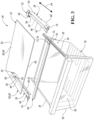
Figure 3 is a perspective exploded view of the drawer-shelf system that is utilized in the refrigerator; and -
Figure 4 is a perspective front view illustrating an engagement between the drawer-shelf system and shelf supports within the refrigerator. - Embodiments of the present disclosure are described herein. It is to be understood, however, that the disclosed embodiments are merely examples and other embodiments may take various and alternative forms. The figures are not necessarily to scale; some features could be exaggerated or minimized to show details of particular components. Therefore, specific structural and functional details disclosed herein are not to be interpreted as limiting, but merely as a representative basis for teaching one skilled in the art to variously employ the embodiments. As those of ordinary skill in the art will understand, various features illustrated and described with reference to any one of the figures may be combined with features illustrated in one or more other figures to produce embodiments that are not explicitly illustrated or described. The combinations of features illustrated provide representative embodiments for typical applications. Various combinations and modifications of the features consistent with the teachings of this disclosure, however, could be desired for particular applications or implementations.
- Referring to
Figure 1 , generally arefrigerator 10 of the side-by-side type is illustrated. However, it should be understood that this disclosure could apply to any type of refrigerator, such as a side-by-side, French-Door Bottom Mount, or a top-mount type. Therefrigerator 10 defines internal cavities. More specifically, therefrigerator 10 defines a fresh food orrefrigeration compartment 12 and afreezer compartment 14 that are separated by a dividingwall 15. It is generally known that thefreezer compartment 14 is typically kept at a temperature below the freezing point of water, and therefrigeration compartment 12 is typically kept at a temperature above the freezing point of water and generally below a temperature of from about 1.5° C. to about 10° C., more typically below about 3.5° C. - The interior of
refrigerator 10, including therefrigeration compartment 12 and thefreezer compartment 14, is cooled by an evaporator (not shown) that is part of a refrigerant circuit. The evaporator may be located in the freezer compartment. The refrigerant circuit also includes a compressor (not shown) and a condenser (not shown), which may be located in amachinery compartment 19. The condenser is configured to reject heat from the refrigerant circuit to the ambient surroundings. Fans may be utilized to direct air across the evaporator and the condenser to facilitate exchanging heat. The compressor and the fans may be connected to a controller. Sensors that measure the air temperature within therefrigeration compartment 12 and thefreezer compartment 14 may be in communication with the controller. The controller may be configured to operate the compressor, fans, etc. in response to the air temperature within therefrigeration compartment 12 and thefreezer compartment 14 being less than a threshold. - Such a controller may be part of a larger control system and may be controlled by various other controllers throughout the
refrigerator 10, and one or more other controllers can collectively be referred to as a "controller" that controls various functions of therefrigerator 10 in response to inputs or signals to control functions of therefrigerator 10. The controller may include a microprocessor or central processing unit (CPU) in communication with various types of computer readable storage devices or media. Computer readable storage devices or media may include volatile and nonvolatile storage in read-only memory (ROM), random-access memory (RAM), and keep-alive memory (KAM), for example. KAM is a persistent or non-volatile memory that may be used to store various operating variables while the CPU is powered down. Computer-readable storage devices or media may be implemented using any of a number of known memory devices such as PROMs (programmable read-only memory), EPROMs (electrically PROM), EEPROMs (electrically erasable PROM), flash memory, or any other electric, magnetic, optical, or combination memory devices capable of storing data, some of which represent executable instructions, used by the controller in controlling therefrigerator 10. - The refrigerator has
openable doors refrigeration compartment 14 and thefreezer compartment 14, respectively. Therefrigeration compartment 12 is provided with one ormore drawers 18 for storing food and one ormore shelves 20 for storing food. Thedrawers 18 may more specifically be crisper drawers that are slidably secured to the internal walls orliner walls 24 within therefrigeration compartment 12. Crisper drawers define storage spaces that are kept at a desired humidity that may be different from the remainder of therefrigeration compartment 12, but that is optimal for maintaining freshness of fruits and vegetables. Thedrawers 18 andshelves 20 are supported by shelf supports 22, that are secured to theliner walls 24 of therefrigeration compartment 12 and protrude into therefrigeration compartment 12. Thefreezer compartment 14 may also includeshelves 20 that are supported by shelf supports 22.Door shelves 26 are secured to the interior sides ofdoors door shelves 26 may be secured to the interior sides ofdoors doors - Referring to
Figures 2 and3 , a drawer-shelf system 28 for therefrigerator 10 is illustrated. The drawer-shelf system 28 may more specifically, be a combination of a drawer 30 (e.g., drawer 18) and a shelf 32 (e.g., shelf 20). Thedrawer 30 and theshelf 32 are illustrated as being constructed from a transparent material (e.g., a transparent glass or plastic). However, it should be understood that thedrawer 30 andshelf 32 may be made from non-transparent materials. Thedrawer 30 may more specifically be a crisper drawer. Thedrawer 30 has at least one support lip orridge 34 protruding therefrom. More specifically, thedrawer 30 may have first andsecond ridges 34 extending outward from opposing first andsecond sides 36 of thedrawer 30. - The drawer-
shelf system 28 includes at least onesupport rail 38 defining adrawer support channel 40 on aninternal side 42 of at least onesupport rail 38. More specifically, the drawer-shelf system 28 may include first and second opposing spaced-apart support rails 38 defining first and seconddrawer support channels 40 along first and secondinternal sides 42 of the first and second support rails 38, respectively. The first and second crisperdrawer support channels 40 are configured to receive the first andsecond ridges 34, respectively, to support thedrawer 30 and such that thedrawer 30 is slidable relative to the first and second support rails 38. More specifically, the first andsecond ridges 34 are configured to slidably engage the first and seconddrawer support channels 40, respectively, such thedrawer 30 is slidable in adirection 44 from front to back ends of the first and second support rails 38, between an open position and a closed position. - Each
support rail 38 defines a shelf mounting recess, channel, or C-channel 46 along a top 48 of therespective support rail 38, along a first orback end 50 of therespective support rail 38, and above the respectivedrawer support channel 40. Eachsupport rail 38 may include aprotrusion 52 extending upward fromback end 50 of thesupport rail 38. Eachprotrusion 52 may define one of the shelf mounting recesses, channels, or C-channels 46. More specifically, the first and second support rails 38 may have first andsecond protrusions 52 extending upward from first and second back ends 50 of the first and second support rails 38, respectively, wherein the first andsecond protrusions 52 define first and second shelf mounting recesses, channels, or C-channels 46, respectively. Each shelf mounting recess, channel, or C-channel 46 may have forward facing open ends 54 (e.g., open ends that face toward afront side 56 of thedrawer 30. - The
shelf 32 may be a planar shelf or a plate forming a shelf. Theshelf 32 has an outer edge 58 extending about an outer periphery 60 of theshelf 32. Portions of the outer edge 58 are configured to slidably engage the shelf mounting recesses, channels, or C-channels 46 to secure theshelf 32 to the support rails 38 such that eachsupport rail 38 supports at least a portion of a weight of theshelf 32. Stated in other terms, portions of the outer edge 58 are configured to be disposed within the shelf mounting recesses, channels, or C-channels 46 of eachsupport rail 38 such that theshelf 32 is supported by the back ends 50 of eachsupport rail 38. More specifically, the portions of the outer edge 58 that are disposed within the shelf mounting recesses, channels, or C-channels 46 of eachsupport rail 38 may be portions of a back edge or backportion 62 of the outer edge 58. - The drawer-
shelf system 28 may further include asupport bar 64 configured to secure a portion of the outer edge 58 to second or front ends 66 of the support rails 38. The portion the outer edge 58 that is secured to front ends 66 of the support rails 38 may be a front edge orfront portion 68 of the outer edge 58. Thesupport bar 64 defines a shelf mounting recess, channel, or C-channel 70. Thefront portion 68 of the outer edge 58 is configured to be or is disposed within the shelf mounting recess, channel, or C-channel 70. - The front ends 66 of the support rails 38 are opposite to the back ends 50 of the support rails 38 (e.g., the front ends 66 of the support rails 38 are on opposite ends of the support rails 38 relative to the back ends 50). The
front portion 68 of the outer edge 58 is opposite to theback portion 62 of the outer edge 58 (e.g., thefront portion 68 of the outer edge 58 is on an opposite end of theshelf 32 relative to theback portion 62 of the outer edge 58). The shelf mounting recess, channel, or C-channel 70 has a rearward facing open end 72 that faces the open ends 54 of the shelf mounting recesses, channels, or C-channels 46. - The drawer-
shelf system 28 may further include horizontally extendingposts 74 disposed on and extending upward from the front ends 66 of eachsupport rail 38. Thesupport bar 64 may engage the horizontally extendingposts 74 to secure thefront portion 68 of the outer edge 58 to the front ends 66 of the support rails 38. More specifically, thesupport bar 64 may engage the horizontally extendingposts 74 to secure theshelf 32 to the front ends 66 of the support rails 38 such that eachfront end 66 of eachsupport rail 38 supports at least a portion of a weight of theshelf 32. Thesupport bar 64 may further define a channel or C-channel 76 that is disposed below the shelf mounting recess, channel, or C-channel 70. The channel or C-channel 76 may also have a rearward facing open end 78 that faces the open ends 54 of the shelf mounting recesses, channels, or C-channels 46. The horizontally extendingposts 74 may be disposed within the channel or C-channel 76 in order to secure thesupport bar 64 andshelf 32 to the front ends 66 of the support rails 38. - Referring now to
Figure 4 , a perspective front view illustrating an engagement between the drawer-shelf system 28 and shelf supports 22 within therefrigerator 10 is illustrated. The image ofFigure 4 only illustrates an engagement along one side of the drawer-shelf system 28 (e.g., the left side). It should be understood, however, that each side of the drawer-shelf system 28 may be secured to a separate shelf support 22 (e.g., the left side and the right side of the drawer-shelf system 28 may each be secured to a separate shelf support 22). Furthermore, it should be understood that each side of the drawer-shelf system 28 (e.g., the left side and the right side of the drawer-shelf system 28) may be mirror images of each other and the shelf supports engaging each side of the drawer-shelf system 28 may also be mirror image versions of each other. - The shelf supports 22 may comprise protrusions that extend from the
liner walls 24 and into the internal cavities defined by the refrigerator 10 (e.g.,refrigeration compartment 12 or freezer compartment 14).Sets 80 of shelf supports 22 may be configured to support adrawer 18, ashelf 20, or a drawer-shelf system 28. Theshelf support 22 toward theback wall 82 of each set 80 of shelf supports 22 may define anotch 84. More specifically, theshelf support 22 toward theback wall 82 of each set 80 of shelf supports 22 may be C-shaped. It is noted that only a left side set 80 of shelf supports 22 (e.g., shelf supports 22 extending from a left side wall) is illustrated inFigure 4 . However, it should be understood each set 80 of shelf supports 22 will have a corresponding mirror image set of shelf supports (e.g., shelf supports 22 extending from a right side wall) so that eachdrawer 18,shelf 20, and drawer-shelf system 28 are supported on both left and right sides. - Referring more specifically to the drawer-
shelf system 28 depicted inFigure 4 , eachsupport rail 38 is configured to slidably engage the at least oneshelf support 22 to secure thesupport rail 38 to therefrigerator 38 within an internal cavity (e.g., refrigeration compartment 12). More specifically, eachprotrusion 52 that extends upward from aback end 50 of eachsupport rail 38 is configured to be received within one of thenotches 84 when the support rails 38 engage the shelf supports 22. - It should be understood that the designations of first, second, third, fourth, etc. for any component, state, or condition described herein may be rearranged in the claims so that they are in chronological order with respect to the claims. Furthermore, it should be understood that any component, state, or condition described herein that does not have a numerical designation may be given a designation of first, second, third, fourth, etc. in the claims if one or more of the specific component, state, or condition are claimed.
Claims (15)
- A refrigerator defining an internal cavity (12,14) and having at least one shelf support (22) protruding into the internal cavity (12,14), the refrigerator comprising a drawer-shelf system (28) havinga support rail (38) defining (i) a crisper drawer support channel (40) on an internal side (42) of the support rail (38) and (ii) a shelf mounting recess (46) along a top (48) of the support rail (38), along a back end (50) of the support rail (38), and above the crisper drawer support channel (40);a crisper drawer (30) having a support lip (34) configured to slidably engage the crisper drawer support channel (40); anda planar shelf (32) having an outer edge (58) extending about an outer periphery (60) of the planar shelf (32), wherein a portion of the outer edge (58) is configured to slidably engage the shelf mounting recess (46) to secure the planar shelf (32) to the support rail (38) such that the support rail (38) supports at least a portion of a weight of the planar shelf (32).
- The refrigerator of claim 1, wherein the shelf mounting recess (46) of the drawer-shelf system (28) is a C-channel.
- The refrigerator of claim 1, wherein (i) the support rail (38) of the drawer-shelf system (28) includes a protrusion (52) extending upward from the back end (50) of the support rail (38) and (ii) the protrusion (52) defines the shelf mounting recess (46).
- The refrigerator of claim 1, wherein the support rail (38) of the drawer-shelf system (28) is configured to slidably engage the at least one shelf support (22) to secure the support rail (38) to the refrigerator (10) within the internal cavity (12,14).
- The refrigerator of claim 1, wherein the drawer-shelf system (28) further comprises a defining (i) a second crisper drawer support channel (40) on an internal side (42) of the second support rail (38) and (ii) a second shelf mounting recess (46) along a top (48) of the second support rail (38), along a back end (50) of the second support rail (38), and above the second crisper drawer support channel (40).
- The refrigerator of claim 5, wherein the second support rail (38) of the drawer-shelf system (28) is configured to slidably engage the at least one shelf support (22) to secure the second support rail (38) to the refrigerator (10) within the internal cavity (12,14).
- The refrigerator of claim 5, wherein the second shelf mounting recess (46) of the second support rail (38) of the drawer-shelf system (28) is a C-channel.
- The refrigerator of claim 5, wherein (i) the second support rail (38) of the drawer-shelf system (28) includes a protrusion (52) extending upward from the back end (50) of the second support rail (38) and (ii) the protrusion (52) defines the second shelf mounting recess (46).
- The refrigerator of claim 1, wherein at least a second portion of the outer edge (58) of the planar shelf (32) of the drawer-shelf system (28) is configured to slidably engage the second shelf mounting recess (46) to secure the planar shelf (32) to the second support rail (38) such that the second support rail (38) supports at least a second portion of the weight of the planar shelf (32).
- The refrigerator of claim 9, wherein the portion of the outer edge (58) and the second portion of the outer edge (58) are each portions of a back edge (62) of the planar shelf (32).
- The refrigerator of claim 10, wherein the drawer-shelf system (28) further comprises a support bar (64) (i) defining a third shelf mounting recess (70) configured to receive a third portion of the outer edge (58) of the planar shelf (32) and (ii) configured to secure the third portion to front ends (66) of the support rail (38) and second support rail (38) opposite to the back ends (50) of the rails (38).
- The refrigerator of claim 11, wherein the third portion of the outer edge (58) is a front edge (68) of the planar shelf (32).
- The refrigerator of claim 11, wherein the support bar (64) of the drawer-shelf system (28) engages horizontally extending posts (74) disposed on the front ends (66) of the support rail (38) and second support rail (38) to secure the third portion of the outer edge (58) of the planar shelf (32) to the front ends (66) of the support rail (38) and second support rail (38).
- The refrigerator of claim 13, wherein the support bar (64) defines a fourth recess (76) below the third shelf mounting recess (70), and wherein the horizontally extending posts (74) are disposed within the fourth recess (76).
- The refrigerator of claim 14, wherein the third shelf mounting recess (70) and fourth recess (76) are C-channels.
Applications Claiming Priority (1)
| Application Number | Priority Date | Filing Date | Title |
|---|---|---|---|
| US17/522,500 US11703272B2 (en) | 2021-11-09 | 2021-11-09 | Drawer-shelf system for a refrigerator appliance |
Publications (1)
| Publication Number | Publication Date |
|---|---|
| EP4177553A1 true EP4177553A1 (en) | 2023-05-10 |
Family
ID=83361234
Family Applications (1)
| Application Number | Title | Priority Date | Filing Date |
|---|---|---|---|
| EP22196002.4A Withdrawn EP4177553A1 (en) | 2021-11-09 | 2022-09-15 | Drawer-shelf system for a refrigerator appliance |
Country Status (2)
| Country | Link |
|---|---|
| US (1) | US11703272B2 (en) |
| EP (1) | EP4177553A1 (en) |
Families Citing this family (1)
| Publication number | Priority date | Publication date | Assignee | Title |
|---|---|---|---|---|
| US20250067504A1 (en) * | 2023-08-24 | 2025-02-27 | Whirlpool Corporation | Refrigerator and corresponding shelving system |
Citations (3)
| Publication number | Priority date | Publication date | Assignee | Title |
|---|---|---|---|---|
| US4870836A (en) * | 1989-03-06 | 1989-10-03 | Amana Refrigeration, Inc. | Air flow control for glass top refrigerator container |
| US20080202146A1 (en) * | 2007-02-26 | 2008-08-28 | Samsung Electronics Co., Ltd. | Drawer type receiving device of a refrigerator |
| CN103673489B (en) * | 2012-09-11 | 2019-01-18 | 海尔集团公司 | A kind of rack, drawer integral type plug-in type drawer runner |
Family Cites Families (9)
| Publication number | Priority date | Publication date | Assignee | Title |
|---|---|---|---|---|
| US4729613A (en) * | 1986-11-13 | 1988-03-08 | General Electric Company | Household refrigerator pan assembly |
| US4960308A (en) * | 1989-10-03 | 1990-10-02 | White Consolidated Industries, Inc. | Support shelf for crisper drawers in refrigerators |
| US5044704A (en) * | 1990-05-17 | 1991-09-03 | Whirlpool Corporation | Adjustable refrigerator crisper drawer structure |
| US5641217A (en) * | 1995-08-02 | 1997-06-24 | Sub-Zero Freezer Company, Inc. | Slide shelf system for a deli/crisper drawer |
| US7497533B2 (en) * | 2003-04-28 | 2009-03-03 | Clairson, Inc. | Shelves, resilient drawer stops, and drawer brackets for supporting shelves and drawers |
| US8403437B2 (en) * | 2004-01-16 | 2013-03-26 | Whirlpool Corporation | Versatile refrigerator crisper system |
| US10485250B2 (en) * | 2017-05-15 | 2019-11-26 | Haier Us Appliance Solutions, Inc. | Produce drawer |
| CN207674812U (en) | 2017-12-26 | 2018-07-31 | 李伟 | Refrigerator drawer hanger component and refrigerator |
| CN211926283U (en) | 2019-12-10 | 2020-11-13 | 惠而浦(中国)股份有限公司 | Refrigerator drawer and refrigerator |
-
2021
- 2021-11-09 US US17/522,500 patent/US11703272B2/en active Active
-
2022
- 2022-09-15 EP EP22196002.4A patent/EP4177553A1/en not_active Withdrawn
Patent Citations (3)
| Publication number | Priority date | Publication date | Assignee | Title |
|---|---|---|---|---|
| US4870836A (en) * | 1989-03-06 | 1989-10-03 | Amana Refrigeration, Inc. | Air flow control for glass top refrigerator container |
| US20080202146A1 (en) * | 2007-02-26 | 2008-08-28 | Samsung Electronics Co., Ltd. | Drawer type receiving device of a refrigerator |
| CN103673489B (en) * | 2012-09-11 | 2019-01-18 | 海尔集团公司 | A kind of rack, drawer integral type plug-in type drawer runner |
Also Published As
| Publication number | Publication date |
|---|---|
| US20230145594A1 (en) | 2023-05-11 |
| US11703272B2 (en) | 2023-07-18 |
Similar Documents
| Publication | Publication Date | Title |
|---|---|---|
| EP3343156A1 (en) | Refrigerator | |
| KR20160090066A (en) | A refrigerator and a method controlling the same | |
| US11703272B2 (en) | Drawer-shelf system for a refrigerator appliance | |
| US12146704B2 (en) | Refrigerator appliance and corresponding shelving system | |
| US11549743B1 (en) | Refrigerator appliance | |
| EP4343242A1 (en) | Refrigerator with a water storage tank | |
| EP4242564A1 (en) | Refrigerator and storage system for a refrigerator | |
| US11920851B2 (en) | Refrigerator appliance | |
| US11713917B2 (en) | Refrigerator appliance with self-adjusting mullion | |
| US20230375254A1 (en) | Refrigerator appliance subcomponent mounting system | |
| US5992166A (en) | Motorized damper for refrigerator | |
| US12320578B2 (en) | Refrigerator and corresponding shelving system | |
| EP4119869A1 (en) | Refrigerator appliance | |
| US12281838B2 (en) | Refrigerator appliance | |
| US12492859B2 (en) | Refrigerator appliance subcomponent mounting system | |
| US20240102721A1 (en) | Refrigerator appliance | |
| US20240410644A1 (en) | Refrigerator appliance subcomponent mounting system | |
| US7260957B2 (en) | Damper for refrigeration apparatus | |
| US20260029188A1 (en) | Refrigerator appliance | |
| US20250362074A1 (en) | Bin storage system for a refrigerator appliance | |
| US11988439B2 (en) | Refrigerator appliance subcomponent mounting system | |
| US12146703B2 (en) | Refrigerator appliance | |
| US20260049756A1 (en) | Refrigerator and storage system for a refrigerator | |
| US20260043604A1 (en) | Refrigerator and storage system for a refrigerator | |
| EP4209741A1 (en) | Refrigerated drawer assembly for a kitchen cabinet |
Legal Events
| Date | Code | Title | Description |
|---|---|---|---|
| PUAI | Public reference made under article 153(3) epc to a published international application that has entered the european phase |
Free format text: ORIGINAL CODE: 0009012 |
|
| STAA | Information on the status of an ep patent application or granted ep patent |
Free format text: STATUS: THE APPLICATION HAS BEEN PUBLISHED |
|
| AK | Designated contracting states |
Kind code of ref document: A1 Designated state(s): AL AT BE BG CH CY CZ DE DK EE ES FI FR GB GR HR HU IE IS IT LI LT LU LV MC MK MT NL NO PL PT RO RS SE SI SK SM TR |
|
| STAA | Information on the status of an ep patent application or granted ep patent |
Free format text: STATUS: REQUEST FOR EXAMINATION WAS MADE |
|
| 17P | Request for examination filed |
Effective date: 20231110 |
|
| P01 | Opt-out of the competence of the unified patent court (upc) registered |
Effective date: 20231110 |
|
| RBV | Designated contracting states (corrected) |
Designated state(s): AL AT BE BG CH CY CZ DE DK EE ES FI FR GB GR HR HU IE IS IT LI LT LU LV MC MK MT NL NO PL PT RO RS SE SI SK SM TR |
|
| STAA | Information on the status of an ep patent application or granted ep patent |
Free format text: STATUS: THE APPLICATION HAS BEEN WITHDRAWN |
|
| 18W | Application withdrawn |
Effective date: 20240625 |