EP4177509A1 - Automatic machine for manufacturing or packing consumer products, in particular of the tobacco industry, and related control method - Google Patents
Automatic machine for manufacturing or packing consumer products, in particular of the tobacco industry, and related control method Download PDFInfo
- Publication number
- EP4177509A1 EP4177509A1 EP22205490.0A EP22205490A EP4177509A1 EP 4177509 A1 EP4177509 A1 EP 4177509A1 EP 22205490 A EP22205490 A EP 22205490A EP 4177509 A1 EP4177509 A1 EP 4177509A1
- Authority
- EP
- European Patent Office
- Prior art keywords
- door
- safety sensor
- closed position
- automatic machine
- processing line
- Prior art date
- Legal status (The legal status is an assumption and is not a legal conclusion. Google has not performed a legal analysis and makes no representation as to the accuracy of the status listed.)
- Granted
Links
Images


Classifications
-
- F—MECHANICAL ENGINEERING; LIGHTING; HEATING; WEAPONS; BLASTING
- F16—ENGINEERING ELEMENTS AND UNITS; GENERAL MEASURES FOR PRODUCING AND MAINTAINING EFFECTIVE FUNCTIONING OF MACHINES OR INSTALLATIONS; THERMAL INSULATION IN GENERAL
- F16P—SAFETY DEVICES IN GENERAL; SAFETY DEVICES FOR PRESSES
- F16P3/00—Safety devices acting in conjunction with the control or operation of a machine; Control arrangements requiring the simultaneous use of two or more parts of the body
- F16P3/08—Safety devices acting in conjunction with the control or operation of a machine; Control arrangements requiring the simultaneous use of two or more parts of the body in connection with the locking of doors, covers, guards, or like members giving access to moving machine parts
-
- A—HUMAN NECESSITIES
- A24—TOBACCO; CIGARS; CIGARETTES; SIMULATED SMOKING DEVICES; SMOKERS' REQUISITES
- A24D—CIGARS; CIGARETTES; TOBACCO SMOKE FILTERS; MOUTHPIECES OF CIGARS OR CIGARETTES; MANUFACTURE OF TOBACCO SMOKE FILTERS OR MOUTHPIECES
- A24D3/00—Tobacco smoke filters, e.g. filter tips or filtering inserts; Filters specially adapted for simulated smoking devices; Mouthpieces of cigars or cigarettes
- A24D3/02—Manufacture of tobacco smoke filters
-
- B—PERFORMING OPERATIONS; TRANSPORTING
- B65—CONVEYING; PACKING; STORING; HANDLING THIN OR FILAMENTARY MATERIAL
- B65B—MACHINES, APPARATUS OR DEVICES FOR, OR METHODS OF, PACKAGING ARTICLES OR MATERIALS; UNPACKING
- B65B19/00—Packaging rod-shaped or tubular articles susceptible to damage by abrasion or pressure, e.g. cigarettes, cigars, macaroni, spaghetti, drinking straws or welding electrodes
- B65B19/02—Packaging cigarettes
- B65B19/22—Wrapping the cigarettes; Packaging the cigarettes in containers formed by folding wrapping material around formers
-
- B—PERFORMING OPERATIONS; TRANSPORTING
- B65—CONVEYING; PACKING; STORING; HANDLING THIN OR FILAMENTARY MATERIAL
- B65B—MACHINES, APPARATUS OR DEVICES FOR, OR METHODS OF, PACKAGING ARTICLES OR MATERIALS; UNPACKING
- B65B57/00—Automatic control, checking, warning, or safety devices
-
- B—PERFORMING OPERATIONS; TRANSPORTING
- B65—CONVEYING; PACKING; STORING; HANDLING THIN OR FILAMENTARY MATERIAL
- B65B—MACHINES, APPARATUS OR DEVICES FOR, OR METHODS OF, PACKAGING ARTICLES OR MATERIALS; UNPACKING
- B65B57/00—Automatic control, checking, warning, or safety devices
- B65B57/005—Safety-devices
-
- A—HUMAN NECESSITIES
- A24—TOBACCO; CIGARS; CIGARETTES; SIMULATED SMOKING DEVICES; SMOKERS' REQUISITES
- A24C—MACHINES FOR MAKING CIGARS OR CIGARETTES
- A24C5/00—Making cigarettes; Making tipping materials for, or attaching filters or mouthpieces to, cigars or cigarettes
Definitions
- the present invention relates to an automatic machine for manufacturing or packing consumer products, in particular of the tobacco industry, and to a related control method.
- the present invention finds advantageous application in the tobacco industry, to which the following disclosure will refer without losing generality.
- An automatic machine for manufacturing or packing products of the tobacco industry comprises at least one processing line which is formed by a plurality of operating members and feeds and combines with one another at least two different materials with which the consumer products (for example, cigarettes, packets, cartons, etc.) are made.
- An automatic machine also comprises a protection barrier that surrounds the processing line and has the function of preventing an operator from approaching the processing line while the processing line is in operation.
- the protection barrier comprises a plurality of doors that can assume a closed position or an open position: while the processing line is in operation, the doors must be strictly closed to ensure the integrity of the protection barrier and therefore the doors can be opened (for example to perform cleaning, maintenance, replacement interventions) only when the processing line is stopped.
- the safety regulations prescribe that each door must be coupled to a corresponding safety sensor which is designed to detect whether the door is in the closed position; a control unit of the automatic machine is configured to allow the operation of the processing line only when each safety sensor detects that the corresponding door is in the closed position.
- the control unit which is notified of the opening by the corresponding safety sensor, immediately stops the processing line in the shortest possible time.
- This manoeuvre (namely, opening a door while the processing line is in operation) should never be done as the correct procedure involves firstly stopping the processing line and, only after the processing line has been stopped, opening a door; however, the safety regulations rightly impose to also provide for the case in which an operator opens a door when the processing line is in operation (namely, at the wrong time).
- the processing line can normally reach a particularly high operating speed (for example, of the order of 400-800 products per minute) and therefore due to the inevitable mechanical inertia, the stopping of the processing line can take several seconds; consequently, it would be possible for an operator who opens a door while the processing line is in operation (namely, at the wrong time) to touch part of the processing line while the processing line is still in motion (even if in a rapid-stop step).
- a particularly high operating speed for example, of the order of 400-800 products per minute
- the stopping of the processing line can take several seconds; consequently, it would be possible for an operator who opens a door while the processing line is in operation (namely, at the wrong time) to touch part of the processing line while the processing line is still in motion (even if in a rapid-stop step).
- the regulations enforce, when the automatic machine is fast and therefore requires a certain time to stop, using a safety sensor provided with a mechanical interlock which, when it is activated, physically prevents the door from opening by holding the door in the closed position; in this way, the risk of an operator opening a door while the processing line is in operation (namely, at the wrong time) is avoided.
- Activation and deactivation of the mechanical interlock are relatively long and laborious (also because the mechanical interlock is designed to be safe, not to be fast) and therefore when the automatic machine is in the assembly or maintenance step the continuous need to perform manual interventions on the processing line interspersed with short actuations of the processing line (or of part of the processing line) to test each time the results of the manual interventions significantly increases the time required to perform the assembly or maintenance interventions.
- the patent EP2352948B1 represents the closest state of the art and describes a safety switch for generating a system enable signal based on the position of a movable guard door that is used to safeguard a hazardous area of a machine installation; namely, at least part of the machine system can only be actuated when the system enable signal is present.
- the purpose of the present invention is to provide an automatic machine for manufacturing or packing consumer products, in particular of the tobacco industry, and a related control method, which allow to reduce the time required to perform assembly or maintenance and are, at the same time, easy and inexpensive to implement.
- an automatic machine for manufacturing or packing consumer products in particular of the tobacco industry, and a related control method are provided, according to what is claimed in the attached claims.
- number 1 denotes, as a whole, an automatic packing machine for manufacturing a rigid packet 2 of cigarettes, which comprises an outer container that is made of cardboard or rigid paperboard, is cup-shaped, houses an inner wrap containing a group 3 of cigarettes, and is provided with a hinged lid.
- the automatic packing machine 1 comprises a frame 4 which rests on the floor and supports a processing line 5 along which the processing (namely, the packing) of the cigarettes is performed.
- the following are arranged along the processing line 5: a forming unit 6 in which the groups 3 of cigarettes are formed in succession, a wrapping unit 7 in which a wrapping sheet (typically made of metallized paper) is folded around each group 3 of cigarettes) to form the corresponding inner wrap, and a wrapping unit 8 in which a blank (typically made of cardboard and already provided with pre-weakened folding lines) is folded around each inner wrap to form the corresponding outer container provided with the hinged lid.
- a feeding unit 9 is coupled to the wrapping unit 7 which feeds the wrapping sheets in succession to form the inner wraps, while a feeding unit 10 is coupled to the wrapping unit 8 which feeds the blanks in succession to form the outer containers 2.
- the automatic packing machine 1 comprises a plurality of operating members (for example linear conveyors, rotating conveyors, gluing units, fixed folders, mobile folders, control members, support heads, pulleys, belts, pushers, pockets for groups 3 of cigarettes, electronic boards, electric motors, electric actuators, pneumatic valves Certainly, the processing line 5 is provided with a plurality of operating members and feeds and combines with one another the materials (cigarettes, wrapping sheets, blanks of paper or paperboard, glues) used by the automatic packing machine 1 with which the consumer products are manufactured, namely, to form the packets 2 of cigarettes.
- operating members for example linear conveyors, rotating conveyors, gluing units, fixed folders, mobile folders, control members, support heads, pulleys, belts, pushers, pockets for groups 3 of cigarettes, electronic boards, electric motors, electric actuators, pneumatic valves .
- the processing line 5 is provided with a plurality of operating members and feeds and combines with one another the materials (cigarettes, wrapping sheets, blanks of
- the automatic packing machine 1 comprises a control unit 11, which supervises the operation of the automatic packing machine 1 and therefore of the processing line 5.
- the automatic packing machine 1 comprises a protection barrier 12 which surrounds the processing line 5 and comprises at least one door 13 which can assume a closed position or an open position (in fact the protection barrier 12 generally comprises a plurality of doors 13 to ensure wide accessibility to the production line 5 when the production line 5 is stopped).
- the automatic packing machine 1 comprises a safety sensor 14 which is designed to detect whether the door 13 is in the closed position and is provided with a mechanical interlock 15 (schematically illustrated in Figure 3 ) which, when it is activated, physically prevents the door 13 from opening by holding the door 13 in the closed position.
- a safety sensor 14 which is designed to detect whether the door 13 is in the closed position and is provided with a mechanical interlock 15 (schematically illustrated in Figure 3 ) which, when it is activated, physically prevents the door 13 from opening by holding the door 13 in the closed position.
- the automatic packing machine 1 comprises another safety sensor 16 which is different and separate from the safety sensor 14, is designed to detect whether the door 13 is in the closed position and is not provided with a mechanical interlock.
- the control unit 11 is configured to allow the processing line 5 to operate (typically for the normal production of consumer products) until reaching a nominal operating speed (namely, a maximum operating speed) only when the safety sensor 14 detects that the door 13 is in the closed position and the mechanical interlock 15 is active.
- a nominal operating speed namely, a maximum operating speed
- control unit 11 is configured to allow the processing line 5 to operate in a test mode and at a limited operating speed and (substantially) lower than the nominal operating speed when the safety sensor 16 detects that the door 13 is in the closed position regardless of what is detected by the safety sensor 14.
- a test mode namely, without actually producing any product unless for testing purposes
- a limited operating speed that is, substantially lower than the nominal operating speed
- the nominal operating speed (namely, the maximum operating speed) of the automatic packing machine 1 can be of the order of 400-800 products per minute, while the limited operating speed is lower than 20%, and preferably 10%. (or even 5%), of the nominal operating speed (namely, the limited operating speed is lower than 40-80 products per minute).
- the assembly or maintenance step is faster as it is possible to perform manual interventions on the processing line 5 interspersed with short actuations of the processing line 5 (or part of the processing line 5) to test each time the result of the manual interventions without having to activate and deactivate the mechanical interlock 15 every time.
- a reference search operation also known as a "homing" operation
- the control circuit moves the axis so as to read a reference signal which identifies the position to be considered as the "zero" of the axis and on this point the counters are reset, and, from that moment, the position of the rotor will be known for the constant updating of the movement relative to this "zero".
- this reference is lost and the system must rotate until it finds its end-stroke in order to establish the exact point where it was set.
- control unit 11 can, therefore, promptly stop (namely, in a fraction of a second) the processing line 5 (due to the fact that the processing line 5 operates at a limited operating speed and the mechanical inertias are very low).
- the safety sensor 16 has a higher coding level than a coding level of the safety sensor 14; that is, the safety sensor 16 has a high coding level (that is, it has the possibility of having more than 1000 different encodings) while the safety sensor 14 has a low coding level (that is, it has the possibility of having from 1 to 9 different encodings).
- control unit 11 is configured to allow the processing line 5 to operate (for the production of the consumer products) until reaching a nominal operating speed only when the safety sensor 14 detects that the door 13 is in the closed position and the mechanical interlock 15 is active and, simultaneously, the safety sensor 16 detects that the door 13 is in the closed position; namely, the safety sensor 16 is used in combination with the safety sensor 14 to simultaneously have both the guarantee (provided only by the safety sensor 14) of the activation of the mechanical interlock 15, and the guarantee (provided only by the safety sensor 16) of a high level of coding. In this way, the safety sensor 14 can be less expensive as it has a low level of coding.
- Each safety sensor 14 or 16 always has two parts that must be coupled: one part integral with the frame 4 and the other part integral with the door 13; the coding level of the safety sensor 14 or 16 denotes the number of possible combinations between the two parts of the safety sensor 14 or 16 and therefore the higher the coding level the more difficult it is to find a part that combines with the other part of the safety sensor 14 or 16.
- the safety sensor 14, being provided with the mechanical interlock 15, must necessarily provide for physical contact between the part integral with the frame 4 and the other part integral with the door 13.
- the safety sensor 16 is a contactless sensor and comprises a reader device 17, which is mounted on the frame 4 (or alternatively on the door 13) and a signalling body 18, which is mounted on the door 13 (or alternatively on the frame 4) so as to face the reader device 17 only when the door 13 is in the closed position.
- the reader device 17 is active (and therefore is powered by electrical energy) and is connected to the control unit 11, while the signalling body 18 is passive (namely, it is completely devoid of electric power).
- the automatic packing machine 1 in addition to the door 13, the automatic packing machine 1 comprises a further door 19 which is different from the door 13 (namely, it has a different shape and/or dimensions than the door 13) and it can be installed alternatively to the door 13 in a different configuration of the automatic packing machine 1. Namely, in a different configuration of the automatic packing machine 1 where it is necessary to install other additional components, the door 13 must be disassembled and replaced by the door 19.
- the door 19 is designed to cooperate with the safety sensor 14 (which has, as previously stated, a low coding) but not with the safety sensor 16 (which has, as previously stated, a high coding); consequently, a further safety sensor 20 is provided which is different and separate from the safety sensor 14 and from the safety sensor 16, is designed to detect whether the door 19 is in the closed position, is not provided with a mechanical interlock and is read by the control unit 11 alternatively to the safety sensor 16 only when the door 19 is installed instead of the door 13.
- the control unit 11 uses the safety sensor 20 alternatively to the safety sensor 16 when the door 19 is installed instead of the door 13.
- the safety sensor 20 (although being different and separate from the safety sensor 16) is structurally completely similar to the safety sensor 16.
- the safety sensor 16 is a contactless sensor and comprises a reader device 17, which is mounted on the frame 4 (or alternatively on the door 13) and a signalling body 18, which is mounted on the door 13 (or alternatively on the frame 4) so as to face the reader device 17 only when the door 13 is in the closed position; similarly, the safety sensor 16 is a contactless sensor and comprises a reader device 21, which is mounted on the frame 4 (or alternatively on the door 19) and a signalling body 22, which is mounted on the door 19 (or alternatively on the frame 4) to be facing the reader device 21 only when the door 19 is in the closed position.
- the signalling body 22 of the safety sensor 20 is completely identical to the signalling body 18 of the safety sensor 16 and, hence, has the exact same coding as the signalling body 18; namely, the two signalling bodies 18 and 22 of the safety sensors 16 and 20 are perfectly identical and therefore interchangeable with one another.
- a reader device 17 and one single signalling body 22 are mounted on the frame 4; consequently, the door 13 supports the signalling body 18 while the door 19 supports the reader device 21.
- an additional control unit 23 is also mounted on the door 19 which communicates with the reader device 21 and communicates with the main control unit 11 (for example, in wireless mode).
- the reader device 17 is mounted on the frame 4, the signalling body 18 is mounted on the door 13, the reader device 21 is mounted on the door 19, and the signalling body 22 is mounted on the frame 4.
- the reader device 17 is mounted on the door 13
- the signalling body 18 is mounted on the frame 4
- the reader device 21 is mounted on the frame 4
- the signalling body 22 is mounted on the door 19.
- number 24 denotes, as a whole, an automatic double packaging machine for manufacturing cigarette filters provided with a double processing line 5 along which the processing (production) of the filters is performed.
- the processing line 5 is formed by a plurality of operating members and feeds and combines with one another the materials (filtering material, paper strips, glue, etc.) forming the filters made by the automatic packaging machine 24.
- the automatic packaging machine 24 could be provided with the protection barrier 12 described above alternatively to the automatic packaging machine 1.
- Figure 6 number 25 denotes, as a whole, an automatic packaging machine for manufacturing disposable cartridges 26 for electronic cigarettes provided with a multiple processing line 5 along which the processing (production) of the disposable cartridges 26 is performed.
- the processing line 5 is formed by a plurality of operating members and feeds and combines with one another the materials (casings, tobacco, filtering material, locking rings ...) forming the disposable cartridges 26 made by the automatic packaging machine 25.
- the automatic packaging machine 25 could be provided with the protection barrier 12 described above alternatively to the automatic packaging machine 1.
- the automatic machine 1 described above has numerous advantages.
- the automatic machine 1 described above allows an assembly or maintenance step to be performed more rapidly in which manual interventions are required on the processing line 5 interspersed with short actuations of the processing line 5 (or part of the processing line 5) to test each time the result of the manual interventions.
- the automatic machine 1 described above is simple and inexpensive to produce, as compared to a similar known automatic machine, it requires only a few hardware modifications that require the addition of commercial components of relatively modest cost.
Landscapes
- Engineering & Computer Science (AREA)
- Mechanical Engineering (AREA)
- General Engineering & Computer Science (AREA)
- Wrapping Of Specific Fragile Articles (AREA)
Abstract
Description
- This Patent Application claims priority from
Italian Patent Application No. 102021000028166 filed on November 5, 2021 - The present invention relates to an automatic machine for manufacturing or packing consumer products, in particular of the tobacco industry, and to a related control method.
- The present invention finds advantageous application in the tobacco industry, to which the following disclosure will refer without losing generality.
- An automatic machine for manufacturing or packing products of the tobacco industry comprises at least one processing line which is formed by a plurality of operating members and feeds and combines with one another at least two different materials with which the consumer products (for example, cigarettes, packets, cartons, etc.) are made. An automatic machine also comprises a protection barrier that surrounds the processing line and has the function of preventing an operator from approaching the processing line while the processing line is in operation. The protection barrier comprises a plurality of doors that can assume a closed position or an open position: while the processing line is in operation, the doors must be strictly closed to ensure the integrity of the protection barrier and therefore the doors can be opened (for example to perform cleaning, maintenance, replacement interventions) only when the processing line is stopped.
- The safety regulations prescribe that each door must be coupled to a corresponding safety sensor which is designed to detect whether the door is in the closed position; a control unit of the automatic machine is configured to allow the operation of the processing line only when each safety sensor detects that the corresponding door is in the closed position. When a door is opened while the processing line is in operation the control unit, which is notified of the opening by the corresponding safety sensor, immediately stops the processing line in the shortest possible time. This manoeuvre (namely, opening a door while the processing line is in operation) should never be done as the correct procedure involves firstly stopping the processing line and, only after the processing line has been stopped, opening a door; however, the safety regulations rightly impose to also provide for the case in which an operator opens a door when the processing line is in operation (namely, at the wrong time).
- The processing line can normally reach a particularly high operating speed (for example, of the order of 400-800 products per minute) and therefore due to the inevitable mechanical inertia, the stopping of the processing line can take several seconds; consequently, it would be possible for an operator who opens a door while the processing line is in operation (namely, at the wrong time) to touch part of the processing line while the processing line is still in motion (even if in a rapid-stop step). For this reason, the regulations enforce, when the automatic machine is fast and therefore requires a certain time to stop, using a safety sensor provided with a mechanical interlock which, when it is activated, physically prevents the door from opening by holding the door in the closed position; in this way, the risk of an operator opening a door while the processing line is in operation (namely, at the wrong time) is avoided.
- Activation and deactivation of the mechanical interlock are relatively long and laborious (also because the mechanical interlock is designed to be safe, not to be fast) and therefore when the automatic machine is in the assembly or maintenance step the continuous need to perform manual interventions on the processing line interspersed with short actuations of the processing line (or of part of the processing line) to test each time the results of the manual interventions significantly increases the time required to perform the assembly or maintenance interventions.
- The patent
EP2352948B1 represents the closest state of the art and describes a safety switch for generating a system enable signal based on the position of a movable guard door that is used to safeguard a hazardous area of a machine installation; namely, at least part of the machine system can only be actuated when the system enable signal is present. - The purpose of the present invention is to provide an automatic machine for manufacturing or packing consumer products, in particular of the tobacco industry, and a related control method, which allow to reduce the time required to perform assembly or maintenance and are, at the same time, easy and inexpensive to implement.
- According to the present invention, an automatic machine for manufacturing or packing consumer products, in particular of the tobacco industry, and a related control method are provided, according to what is claimed in the attached claims.
- The claims describe preferred embodiments of the present invention forming an integral part of the present description.
- The present invention will now be described with reference to the attached drawings, which illustrate a non-limiting embodiment thereof, wherein:
-
Figure 1 is a schematic and front view of a packing machine which manufactures rigid packets of cigarettes and is made according to the present invention; -
Figure 2 is a schematic view of a protection barrier of the packing machine ofFigure 1 ; -
Figure 3 is a schematic view of a first door of the packing machine ofFigure 1 ; -
Figure 4 is a schematic view of a second door of the packing machine ofFigure 1 , which is mounted alternatively to the first door ofFigure 3 ; -
Figure 5 is a schematic and front view of a double machine for manufacturing filters made according to the present invention; and -
Figure 6 is a perspective view of a packaging machine which manufactures single-dose cartridges for electronic cigarettes and is made according to the present invention. - In
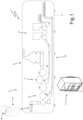
Figure 1 ,number 1 denotes, as a whole, an automatic packing machine for manufacturing arigid packet 2 of cigarettes, which comprises an outer container that is made of cardboard or rigid paperboard, is cup-shaped, houses an inner wrap containing agroup 3 of cigarettes, and is provided with a hinged lid. - The
automatic packing machine 1 comprises aframe 4 which rests on the floor and supports aprocessing line 5 along which the processing (namely, the packing) of the cigarettes is performed. The following are arranged along the processing line 5: a forming unit 6 in which thegroups 3 of cigarettes are formed in succession, awrapping unit 7 in which a wrapping sheet (typically made of metallized paper) is folded around eachgroup 3 of cigarettes) to form the corresponding inner wrap, and a wrapping unit 8 in which a blank (typically made of cardboard and already provided with pre-weakened folding lines) is folded around each inner wrap to form the corresponding outer container provided with the hinged lid. Afeeding unit 9 is coupled to thewrapping unit 7 which feeds the wrapping sheets in succession to form the inner wraps, while afeeding unit 10 is coupled to the wrapping unit 8 which feeds the blanks in succession to form theouter containers 2. - The
automatic packing machine 1 comprises a plurality of operating members (for example linear conveyors, rotating conveyors, gluing units, fixed folders, mobile folders, control members, support heads, pulleys, belts, pushers, pockets forgroups 3 of cigarettes, electronic boards, electric motors, electric actuators, pneumatic valves ...), which are distributed along theprocessing line 5 to form the processing line 5 (namely to form the various units 6-10 of which theprocessing line 5 is composed). In other words, theprocessing line 5 is provided with a plurality of operating members and feeds and combines with one another the materials (cigarettes, wrapping sheets, blanks of paper or paperboard, glues) used by theautomatic packing machine 1 with which the consumer products are manufactured, namely, to form thepackets 2 of cigarettes. - Furthermore, the
automatic packing machine 1 comprises acontrol unit 11, which supervises the operation of theautomatic packing machine 1 and therefore of theprocessing line 5. - According to what is illustrated in
Figure 2 , theautomatic packing machine 1 comprises aprotection barrier 12 which surrounds theprocessing line 5 and comprises at least onedoor 13 which can assume a closed position or an open position (in fact theprotection barrier 12 generally comprises a plurality ofdoors 13 to ensure wide accessibility to theproduction line 5 when theproduction line 5 is stopped). - The
automatic packing machine 1 comprises asafety sensor 14 which is designed to detect whether thedoor 13 is in the closed position and is provided with a mechanical interlock 15 (schematically illustrated inFigure 3 ) which, when it is activated, physically prevents thedoor 13 from opening by holding thedoor 13 in the closed position. - The
automatic packing machine 1 comprises anothersafety sensor 16 which is different and separate from thesafety sensor 14, is designed to detect whether thedoor 13 is in the closed position and is not provided with a mechanical interlock. - The
control unit 11 is configured to allow theprocessing line 5 to operate (typically for the normal production of consumer products) until reaching a nominal operating speed (namely, a maximum operating speed) only when thesafety sensor 14 detects that thedoor 13 is in the closed position and themechanical interlock 15 is active. In other words, it is possible to operate the processing line 5 (typically for the normal production of consumer products) even at high operating speeds (therefore until reaching a nominal operating speed) only when thesafety sensor 14 signals that thedoor 13 is in the closed position and, at the same time, themechanical interlock 15 is active. - Furthermore, the
control unit 11 is configured to allow theprocessing line 5 to operate in a test mode and at a limited operating speed and (substantially) lower than the nominal operating speed when thesafety sensor 16 detects that thedoor 13 is in the closed position regardless of what is detected by thesafety sensor 14. In other words, it is possible to operate theprocessing line 5 in a test mode (namely, without actually producing any product unless for testing purposes) and at a limited operating speed (that is, substantially lower than the nominal operating speed) when thesafety sensor 16 detects that thedoor 13 is in the closed position and without taking into account what is detected by the safety sensor 14 (namely, without themechanical interlock 15 necessarily being active). - By way of example, the nominal operating speed (namely, the maximum operating speed) of the
automatic packing machine 1 can be of the order of 400-800 products per minute, while the limited operating speed is lower than 20%, and preferably 10%. (or even 5%), of the nominal operating speed (namely, the limited operating speed is lower than 40-80 products per minute). - In this way, in the normal operation of the automatic packing machine 1 (namely, when the
automatic packing machine 1 is used for the normal production of consumer products) it is always necessary that thedoor 13 is in the closed position and, at the same time, themechanical interlock 15 is active. Whereas, during an assembly or maintenance step it is possible to operate theprocessing line 5 in a test mode and at a limited operating speed and (significantly) lower than the nominal operating speed even without activating the mechanical interlock 15 (namely, only by placing thedoor 13 in the closed position); in this way, the assembly or maintenance step is faster as it is possible to perform manual interventions on theprocessing line 5 interspersed with short actuations of the processing line 5 (or part of the processing line 5) to test each time the result of the manual interventions without having to activate and deactivate themechanical interlock 15 every time. - For example, during the assembly or maintenance step it is possible to quickly perform a reference search operation (also known as a "homing" operation) of the electric motors; during a reference search operation the control circuit moves the axis so as to read a reference signal which identifies the position to be considered as the "zero" of the axis and on this point the counters are reset, and, from that moment, the position of the rotor will be known for the constant updating of the movement relative to this "zero". For example, in the case of absence of an electrical signal, this reference is lost and the system must rotate until it finds its end-stroke in order to establish the exact point where it was set.
- It is important to underline that, without activating the
mechanical interlock 15, it is possible to operate theprocessing line 5 in a test mode and at a limited operating speed and (substantially) lower than the nominal operating speed; therefore in the event of sudden and unexpected opening of thedoor 13 with theprocessing line 5 in operation, thecontrol unit 11 can, therefore, promptly stop (namely, in a fraction of a second) the processing line 5 (due to the fact that theprocessing line 5 operates at a limited operating speed and the mechanical inertias are very low). Consequently, the safety of the operators is always guaranteed because from the opening of thedoor 13 to the complete stop of theprocessing line 5, very little time passes (a fraction of a second) that, in any case, an operator who opens the door 13 (at the wrong time) does not have the physical time to touch moving parts. - According to a possible embodiment, the
safety sensor 16 has a higher coding level than a coding level of thesafety sensor 14; that is, thesafety sensor 16 has a high coding level (that is, it has the possibility of having more than 1000 different encodings) while thesafety sensor 14 has a low coding level (that is, it has the possibility of having from 1 to 9 different encodings). In this embodiment, thecontrol unit 11 is configured to allow theprocessing line 5 to operate (for the production of the consumer products) until reaching a nominal operating speed only when thesafety sensor 14 detects that thedoor 13 is in the closed position and themechanical interlock 15 is active and, simultaneously, thesafety sensor 16 detects that thedoor 13 is in the closed position; namely, thesafety sensor 16 is used in combination with thesafety sensor 14 to simultaneously have both the guarantee (provided only by the safety sensor 14) of the activation of themechanical interlock 15, and the guarantee (provided only by the safety sensor 16) of a high level of coding. In this way, thesafety sensor 14 can be less expensive as it has a low level of coding. - Each
safety sensor frame 4 and the other part integral with thedoor 13; the coding level of thesafety sensor safety sensor safety sensor - The
safety sensor 14, being provided with themechanical interlock 15, must necessarily provide for physical contact between the part integral with theframe 4 and the other part integral with thedoor 13. - According to a preferred embodiment illustrated in
Figure 3 , thesafety sensor 16 is a contactless sensor and comprises areader device 17, which is mounted on the frame 4 (or alternatively on the door 13) and asignalling body 18, which is mounted on the door 13 (or alternatively on the frame 4) so as to face thereader device 17 only when thedoor 13 is in the closed position. Thereader device 17 is active (and therefore is powered by electrical energy) and is connected to thecontrol unit 11, while thesignalling body 18 is passive (namely, it is completely devoid of electric power). - According to a possible embodiment illustrated in
Figures 3 and4 , in addition to thedoor 13, theautomatic packing machine 1 comprises afurther door 19 which is different from the door 13 (namely, it has a different shape and/or dimensions than the door 13) and it can be installed alternatively to thedoor 13 in a different configuration of theautomatic packing machine 1. Namely, in a different configuration of theautomatic packing machine 1 where it is necessary to install other additional components, thedoor 13 must be disassembled and replaced by thedoor 19. - The
door 19 is designed to cooperate with the safety sensor 14 (which has, as previously stated, a low coding) but not with the safety sensor 16 (which has, as previously stated, a high coding); consequently, afurther safety sensor 20 is provided which is different and separate from thesafety sensor 14 and from thesafety sensor 16, is designed to detect whether thedoor 19 is in the closed position, is not provided with a mechanical interlock and is read by thecontrol unit 11 alternatively to thesafety sensor 16 only when thedoor 19 is installed instead of thedoor 13. Namely, thecontrol unit 11 uses thesafety sensor 20 alternatively to thesafety sensor 16 when thedoor 19 is installed instead of thedoor 13. Preferably, the safety sensor 20 (although being different and separate from the safety sensor 16) is structurally completely similar to thesafety sensor 16. - According to a preferred embodiment, the
safety sensor 16 is a contactless sensor and comprises areader device 17, which is mounted on the frame 4 (or alternatively on the door 13) and asignalling body 18, which is mounted on the door 13 (or alternatively on the frame 4) so as to face thereader device 17 only when thedoor 13 is in the closed position; similarly, thesafety sensor 16 is a contactless sensor and comprises areader device 21, which is mounted on the frame 4 (or alternatively on the door 19) and asignalling body 22, which is mounted on the door 19 (or alternatively on the frame 4) to be facing thereader device 21 only when thedoor 19 is in the closed position. - According to a preferred embodiment, the
signalling body 22 of thesafety sensor 20 is completely identical to thesignalling body 18 of thesafety sensor 16 and, hence, has the exact same coding as thesignalling body 18; namely, the twosignalling bodies safety sensors - According to a preferred embodiment illustrated in
Figures 3 and4 , areader device 17 and onesingle signalling body 22 are mounted on theframe 4; consequently, thedoor 13 supports the signallingbody 18 while thedoor 19 supports thereader device 21. In this embodiment, anadditional control unit 23 is also mounted on thedoor 19 which communicates with thereader device 21 and communicates with the main control unit 11 (for example, in wireless mode). - In particular, in the embodiment illustrated in
Figures 3 and4 , thereader device 17 is mounted on theframe 4, the signallingbody 18 is mounted on thedoor 13, thereader device 21 is mounted on thedoor 19, and the signallingbody 22 is mounted on theframe 4. Instead, according to an alternative embodiment not illustrated, thereader device 17 is mounted on thedoor 13, the signallingbody 18 is mounted on theframe 4, thereader device 21 is mounted on theframe 4, and the signallingbody 22 is mounted on thedoor 19. - In
Figure 5 ,number 24 denotes, as a whole, an automatic double packaging machine for manufacturing cigarette filters provided with adouble processing line 5 along which the processing (production) of the filters is performed. In other words, theprocessing line 5 is formed by a plurality of operating members and feeds and combines with one another the materials (filtering material, paper strips, glue, etc.) forming the filters made by theautomatic packaging machine 24. Theautomatic packaging machine 24 could be provided with theprotection barrier 12 described above alternatively to theautomatic packaging machine 1. - In
Figure 6 number 25 denotes, as a whole, an automatic packaging machine for manufacturingdisposable cartridges 26 for electronic cigarettes provided with amultiple processing line 5 along which the processing (production) of thedisposable cartridges 26 is performed. In other words, theprocessing line 5 is formed by a plurality of operating members and feeds and combines with one another the materials (casings, tobacco, filtering material, locking rings ...) forming thedisposable cartridges 26 made by theautomatic packaging machine 25. Theautomatic packaging machine 25 could be provided with theprotection barrier 12 described above alternatively to theautomatic packaging machine 1. - The embodiments described herein can be combined with one another without departing from the scope of the present invention.
- The
automatic machine 1 described above has numerous advantages. - In the first place, the
automatic machine 1 described above allows an assembly or maintenance step to be performed more rapidly in which manual interventions are required on theprocessing line 5 interspersed with short actuations of the processing line 5 (or part of the processing line 5) to test each time the result of the manual interventions. - Furthermore, the
automatic machine 1 described above is simple and inexpensive to produce, as compared to a similar known automatic machine, it requires only a few hardware modifications that require the addition of commercial components of relatively modest cost. -
- 1
- automatic machine
- 2
- packet of cigarettes
- 3
- group of cigarettes
- 4
- frame
- 5
- processing line
- 6
- forming unit
- 7
- wrapping unit
- 8
- wrapping unit
- 9
- feeding unit
- 10
- feeding unit
- 11
- control unit
- 12
- protection barrier
- 13
- door
- 14
- safety sensor
- 15
- mechanical interlock
- 16
- safety sensor
- 17
- reader device
- 18
- signalling body
- 19
- door
- 20
- safety sensor
- 21
- reader device
- 22
- signalling body
- 23
- control unit
- 24
- automatic machine
- 25
- automatic machine
- 26
- disposable cartridges
Claims (12)
- An automatic machine (1, 24, 25) for manufacturing or packing consumer products, in particular of the tobacco industry; the automatic machine (1, 24, 25) comprises:at least one processing line (5), which is provided with a plurality of operating members and feeds at least one material with which the consumer products are manufactured;a protection barrier (12), which surrounds the processing line (5) and comprises at least one first door (13), which can assume a closed position or an open position;a first safety sensor (14), which is designed to detect whether the first door (13) is in the closed position and is provided with a mechanical interlock (15), which, when it is activated, physically prevents the first door (13) from opening by holding the first door (13) in the closed position;a control unit (11), which is configured to allow the processing line (5) to operate until reaching a nominal operating speed, only when the first safety sensor (14) detects that the first door (13) is in the closed position and the mechanical interlock (15) is active; anda second safety sensor (16), which is different and separate from the first safety sensor (14), is designed to detect whether the first door (13) is in the closed position and is not provided with a mechanical interlock;the automatic machine (1, 24, 25) is characterized in that the control unit (11) is configured to allow the processing line (5) to operate in a test mode and only at a limited operating speed, which is lower than the nominal operating speed, when the second safety sensor (16) detects that the first door (13) is in the closed position, regardless of what is detected by the first safety sensor (14).
- The automatic machine (1, 24, 25) according to claim 1, wherein the control unit (11) is configured to allow the processing line (5) to operate until reaching the nominal operating speed, only when the first safety sensor (14) detects that the first door (13) is in the closed position and the mechanical interlock (15) is active and, simultaneously, the second safety sensor (16) detects that the first door (13) is in the closed position.
- The automatic machine (1, 24, 25) according to claim 2, wherein the second safety sensor (16) has a higher coding level than a coding level of the first safety sensor (14).
- The automatic machine (1, 24, 25) according to claim 1, 2 or 3, wherein the second safety sensor (16) is a contactless sensor and comprises a reader device (17), which is mounted on a frame (4) or on the first door (13), and a signalling body (18), which is mounted on the first door (13) or on the frame (4) so as to face the reader device (17) only when the first door (13) is in the closed position.
- The automatic machine (1, 24, 25) according to one of the claims from 1 to 4 and comprising:a second door (19), which can be installed alternatively to the first door (13) in a different configuration of the automatic machine (1, 24, 25) and is designed to cooperate with the first safety sensor (14), but not with the second safety sensor (16); anda third safety sensor (20), which is different and separate from the first safety sensor (14), is designed to detect whether the second door (19) is in the closed position, is not provided with a mechanical interlock and is read by the control unit (11) alternatively to the second safety sensor (16) only when the second door (19) is installed instead of the first door (13).
- The automatic machine (1, 24, 25) according to claim 5, wherein:the second safety sensor (16) is a contactless sensor and comprises a first reader device (17), which is mounted on a frame (4) or on the first door (13), and a first signalling body (18), which is mounted on the first door (13) or on the frame (4) so as to face the first reader device (17) only when the first door (13) is in the closed position; andthe second safety sensor (16) is a contactless sensor and comprises a second reader device (21), which is mounted on the frame (4) or on the second door (19), and a second signalling body (22), which is mounted on the second door (19) or on the frame (4) so as to face the second reader device (21) only when the second door (19) is in the closed position.
- The automatic machine (1, 24, 25) according to claim 6, wherein the second signalling body (22) is completely identical to the first signalling body (18) and, hence, has the exact same coding as the first signalling body (18).
- The automatic machine (1, 24, 25) according to claim 6 or 7, wherein one single reader device (17) and one single signalling body (22) are mounted on the frame (4).
- The automatic machine (1, 24, 25) according to claim 8, wherein:the first reader device (17) is mounted on the frame (4);the first signalling body (18) is mounted on the first door (13) ;the second reader device (21) is mounted on the second door (19) ;the second signalling body (22) is mounted on the frame (4).
- The automatic machine (1, 24, 25) according to claim 8, wherein:the first reader device (17) is mounted on the first door (13);the first signalling body (18) is mounted on the frame (4);the second reader device (21) is mounted on the frame (4);the second signalling body (22) is mounted on the second door (19) .
- The automatic machine (1, 24, 25) according to one of the claims from 1 to 10, wherein the limited operating speed is lower than 20%, and preferably 10% of the nominal operating speed.
- A method to control an automatic machine (1, 24, 25) for manufacturing or packing consumer products, in particular of the tobacco industry; the automatic machine (1, 24, 25) comprises:
at least one processing line (5), which is provided with a plurality of operating members and feeds at least one material with which the consumer products are manufactured; and a protection barrier (12), which surrounds the processing line (5) and comprises at least one door (13), which can assume a closed position or an open position; the control method comprises the steps of:detecting whether the door (13) is in the closed position by means of a first safety sensor (14), which is provided with a mechanical interlock (15), which, when it is activated, physically prevents the first door (13) from opening by holding the door (13) in the closed position;allowing the processing line (5) to operate until reaching a nominal operating speed, only when the first safety sensor (14) detects that the door (13) is in the closed position and the mechanical interlock (15) is active; anddetecting whether the door (13) is in the closed position by means of a second safety sensor (16), which is different and separate from the first safety sensor (14) and is not provided with a mechanical interlock;the automatic machine (1, 24, 25) is characterized in that it comprises the further step of allowing the processing line (5) to operate in a test mode and only at a limited operating speed, which is lower than the nominal operating speed, when the second safety sensor (16) detects that the door (13) is in the closed position, regardless of what is detected by the first safety sensor (14).
Applications Claiming Priority (1)
| Application Number | Priority Date | Filing Date | Title |
|---|---|---|---|
| IT102021000028166A IT202100028166A1 (en) | 2021-11-05 | 2021-11-05 | AUTOMATIC MACHINE FOR THE PRODUCTION OR PACKAGING OF CONSUMER PRODUCTS, PARTICULARLY FROM THE TOBACCO INDUSTRY, AND RELATED CONTROL METHOD |
Publications (2)
| Publication Number | Publication Date |
|---|---|
| EP4177509A1 true EP4177509A1 (en) | 2023-05-10 |
| EP4177509B1 EP4177509B1 (en) | 2024-05-22 |
Family
ID=79270316
Family Applications (1)
| Application Number | Title | Priority Date | Filing Date |
|---|---|---|---|
| EP22205490.0A Active EP4177509B1 (en) | 2021-11-05 | 2022-11-04 | Automatic machine for manufacturing or packing consumer products, in particular of the tobacco industry, and related control method |
Country Status (3)
| Country | Link |
|---|---|
| EP (1) | EP4177509B1 (en) |
| IT (1) | IT202100028166A1 (en) |
| PL (1) | PL4177509T3 (en) |
Citations (5)
| Publication number | Priority date | Publication date | Assignee | Title |
|---|---|---|---|---|
| DE102012111342A1 (en) * | 2012-11-23 | 2014-05-28 | Pilz Gmbh & Co. Kg | Protective door monitoring system |
| EP2871402A1 (en) * | 2013-11-08 | 2015-05-13 | Sick Ag | Modular safety switch |
| EP2352948B1 (en) | 2008-11-25 | 2016-05-04 | Pilz GmbH & Co. KG | Safety switch for creating a system release signal in dependence on the position of a movable guard door |
| DE102016221359A1 (en) * | 2016-10-28 | 2018-05-03 | Siemens Aktiengesellschaft | Arrangement and method for protecting a device |
| EP3474305A1 (en) * | 2017-10-18 | 2019-04-24 | EUCHNER GmbH + Co. KG | Safety switch |
-
2021
- 2021-11-05 IT IT102021000028166A patent/IT202100028166A1/en unknown
-
2022
- 2022-11-04 PL PL22205490.0T patent/PL4177509T3/en unknown
- 2022-11-04 EP EP22205490.0A patent/EP4177509B1/en active Active
Patent Citations (5)
| Publication number | Priority date | Publication date | Assignee | Title |
|---|---|---|---|---|
| EP2352948B1 (en) | 2008-11-25 | 2016-05-04 | Pilz GmbH & Co. KG | Safety switch for creating a system release signal in dependence on the position of a movable guard door |
| DE102012111342A1 (en) * | 2012-11-23 | 2014-05-28 | Pilz Gmbh & Co. Kg | Protective door monitoring system |
| EP2871402A1 (en) * | 2013-11-08 | 2015-05-13 | Sick Ag | Modular safety switch |
| DE102016221359A1 (en) * | 2016-10-28 | 2018-05-03 | Siemens Aktiengesellschaft | Arrangement and method for protecting a device |
| EP3474305A1 (en) * | 2017-10-18 | 2019-04-24 | EUCHNER GmbH + Co. KG | Safety switch |
Also Published As
| Publication number | Publication date |
|---|---|
| IT202100028166A1 (en) | 2023-05-05 |
| PL4177509T3 (en) | 2024-08-05 |
| EP4177509B1 (en) | 2024-05-22 |
Similar Documents
| Publication | Publication Date | Title |
|---|---|---|
| CA1318335C (en) | Stack stripper for a stacking machine | |
| WO2008114191A2 (en) | Method and apparatus for selective folding or redirecting | |
| US20130209215A1 (en) | Apparatus and method for feeding stacks of tissues or similar folded products to an automatic packaging system | |
| EP2668104B1 (en) | Command and control apparatus to control and command operating units of a packing machine and corresponding method | |
| EP4177509B1 (en) | Automatic machine for manufacturing or packing consumer products, in particular of the tobacco industry, and related control method | |
| US20040083690A1 (en) | Sleeve type packaging machine system, particularly useful for changing reels | |
| US4738073A (en) | Device for forming and controlling the outer wrapping of packs in a cigarette packaging machine | |
| EP3487767B1 (en) | Machine for producing filter-bags with infusion products and with an overwrap envelope | |
| EP3864334B1 (en) | Control system for controlling the access to tissue paper converting lines and the like, and related method | |
| WO2018229806A1 (en) | Packaging machine with tray detection system and operating method thereof | |
| US8196501B2 (en) | Apparatus for slabbing a roll of material | |
| US7298111B2 (en) | Method and device for controlling a production unit | |
| WO1992010405A3 (en) | Servo motor operated indexing motion packaging machine and method | |
| EP4371894A1 (en) | Process for the management of waste with semifinished product recirculation for an automatic machine for manufacturing or packing consumer articles | |
| EP2426071B1 (en) | Conveying system with a braking unit | |
| IT202000003482A1 (en) | Process for the selective management of alarms of an automatic machine for the production or packaging of consumables. | |
| EP2495626A1 (en) | Method of controlling the electric drive of an automatic manufacturing machine, and automatic manufacturing machine with electric drive control | |
| KR20240050329A (en) | Servo-controlled machine line | |
| EP0863078B1 (en) | Machine for cellophaning packets of cigarettes | |
| US20260028146A1 (en) | Method for controlling the movement of an operating assembly of an apparatus for the automatic processing of articles | |
| EP4046924B1 (en) | Packer machine and wrapping method to produce a pack using at least one wrapping material | |
| CN214931018U (en) | Material arranging system and packaging machine thereof | |
| WO2004085261A2 (en) | Unit for applying opening devices to packages of pourable food products | |
| EP4647379A1 (en) | Magazine apparatus for a packaging machine, packaging machine having a magazine apparatus and a packaging plant | |
| US20260077896A1 (en) | Machine for forming filter bags for infusion products |
Legal Events
| Date | Code | Title | Description |
|---|---|---|---|
| PUAI | Public reference made under article 153(3) epc to a published international application that has entered the european phase |
Free format text: ORIGINAL CODE: 0009012 |
|
| STAA | Information on the status of an ep patent application or granted ep patent |
Free format text: STATUS: THE APPLICATION HAS BEEN PUBLISHED |
|
| AK | Designated contracting states |
Kind code of ref document: A1 Designated state(s): AL AT BE BG CH CY CZ DE DK EE ES FI FR GB GR HR HU IE IS IT LI LT LU LV MC ME MK MT NL NO PL PT RO RS SE SI SK SM TR |
|
| STAA | Information on the status of an ep patent application or granted ep patent |
Free format text: STATUS: REQUEST FOR EXAMINATION WAS MADE |
|
| 17P | Request for examination filed |
Effective date: 20231010 |
|
| RBV | Designated contracting states (corrected) |
Designated state(s): AL AT BE BG CH CY CZ DE DK EE ES FI FR GB GR HR HU IE IS IT LI LT LU LV MC ME MK MT NL NO PL PT RO RS SE SI SK SM TR |
|
| GRAP | Despatch of communication of intention to grant a patent |
Free format text: ORIGINAL CODE: EPIDOSNIGR1 |
|
| STAA | Information on the status of an ep patent application or granted ep patent |
Free format text: STATUS: GRANT OF PATENT IS INTENDED |
|
| INTG | Intention to grant announced |
Effective date: 20231212 |
|
| GRAS | Grant fee paid |
Free format text: ORIGINAL CODE: EPIDOSNIGR3 |
|
| P01 | Opt-out of the competence of the unified patent court (upc) registered |
Effective date: 20240229 |
|
| GRAA | (expected) grant |
Free format text: ORIGINAL CODE: 0009210 |
|
| STAA | Information on the status of an ep patent application or granted ep patent |
Free format text: STATUS: THE PATENT HAS BEEN GRANTED |
|
| AK | Designated contracting states |
Kind code of ref document: B1 Designated state(s): AL AT BE BG CH CY CZ DE DK EE ES FI FR GB GR HR HU IE IS IT LI LT LU LV MC ME MK MT NL NO PL PT RO RS SE SI SK SM TR |
|
| REG | Reference to a national code |
Ref country code: GB Ref legal event code: FG4D |
|
| REG | Reference to a national code |
Ref country code: CH Ref legal event code: EP |
|
| REG | Reference to a national code |
Ref country code: DE Ref legal event code: R096 Ref document number: 602022003588 Country of ref document: DE |
|
| REG | Reference to a national code |
Ref country code: IE Ref legal event code: FG4D |
|
| REG | Reference to a national code |
Ref country code: NL Ref legal event code: FP |
|
| REG | Reference to a national code |
Ref country code: LT Ref legal event code: MG9D |
|
| PG25 | Lapsed in a contracting state [announced via postgrant information from national office to epo] |
Ref country code: IS Free format text: LAPSE BECAUSE OF FAILURE TO SUBMIT A TRANSLATION OF THE DESCRIPTION OR TO PAY THE FEE WITHIN THE PRESCRIBED TIME-LIMIT Effective date: 20240922 |
|
| PG25 | Lapsed in a contracting state [announced via postgrant information from national office to epo] |
Ref country code: BG Free format text: LAPSE BECAUSE OF FAILURE TO SUBMIT A TRANSLATION OF THE DESCRIPTION OR TO PAY THE FEE WITHIN THE PRESCRIBED TIME-LIMIT Effective date: 20240522 |
|
| PG25 | Lapsed in a contracting state [announced via postgrant information from national office to epo] |
Ref country code: HR Free format text: LAPSE BECAUSE OF FAILURE TO SUBMIT A TRANSLATION OF THE DESCRIPTION OR TO PAY THE FEE WITHIN THE PRESCRIBED TIME-LIMIT Effective date: 20240522 Ref country code: FI Free format text: LAPSE BECAUSE OF FAILURE TO SUBMIT A TRANSLATION OF THE DESCRIPTION OR TO PAY THE FEE WITHIN THE PRESCRIBED TIME-LIMIT Effective date: 20240522 |
|
| PG25 | Lapsed in a contracting state [announced via postgrant information from national office to epo] |
Ref country code: GR Free format text: LAPSE BECAUSE OF FAILURE TO SUBMIT A TRANSLATION OF THE DESCRIPTION OR TO PAY THE FEE WITHIN THE PRESCRIBED TIME-LIMIT Effective date: 20240823 |
|
| PG25 | Lapsed in a contracting state [announced via postgrant information from national office to epo] |
Ref country code: PT Free format text: LAPSE BECAUSE OF FAILURE TO SUBMIT A TRANSLATION OF THE DESCRIPTION OR TO PAY THE FEE WITHIN THE PRESCRIBED TIME-LIMIT Effective date: 20240923 |
|
| REG | Reference to a national code |
Ref country code: AT Ref legal event code: MK05 Ref document number: 1689038 Country of ref document: AT Kind code of ref document: T Effective date: 20240522 |
|
| PG25 | Lapsed in a contracting state [announced via postgrant information from national office to epo] |
Ref country code: ES Free format text: LAPSE BECAUSE OF FAILURE TO SUBMIT A TRANSLATION OF THE DESCRIPTION OR TO PAY THE FEE WITHIN THE PRESCRIBED TIME-LIMIT Effective date: 20240522 |
|
| PG25 | Lapsed in a contracting state [announced via postgrant information from national office to epo] |
Ref country code: AT Free format text: LAPSE BECAUSE OF FAILURE TO SUBMIT A TRANSLATION OF THE DESCRIPTION OR TO PAY THE FEE WITHIN THE PRESCRIBED TIME-LIMIT Effective date: 20240522 |
|
| PG25 | Lapsed in a contracting state [announced via postgrant information from national office to epo] |
Ref country code: LV Free format text: LAPSE BECAUSE OF FAILURE TO SUBMIT A TRANSLATION OF THE DESCRIPTION OR TO PAY THE FEE WITHIN THE PRESCRIBED TIME-LIMIT Effective date: 20240522 |
|
| PG25 | Lapsed in a contracting state [announced via postgrant information from national office to epo] |
Ref country code: PT Free format text: LAPSE BECAUSE OF FAILURE TO SUBMIT A TRANSLATION OF THE DESCRIPTION OR TO PAY THE FEE WITHIN THE PRESCRIBED TIME-LIMIT Effective date: 20240923 Ref country code: NO Free format text: LAPSE BECAUSE OF FAILURE TO SUBMIT A TRANSLATION OF THE DESCRIPTION OR TO PAY THE FEE WITHIN THE PRESCRIBED TIME-LIMIT Effective date: 20240822 Ref country code: LV Free format text: LAPSE BECAUSE OF FAILURE TO SUBMIT A TRANSLATION OF THE DESCRIPTION OR TO PAY THE FEE WITHIN THE PRESCRIBED TIME-LIMIT Effective date: 20240522 Ref country code: IS Free format text: LAPSE BECAUSE OF FAILURE TO SUBMIT A TRANSLATION OF THE DESCRIPTION OR TO PAY THE FEE WITHIN THE PRESCRIBED TIME-LIMIT Effective date: 20240922 Ref country code: HR Free format text: LAPSE BECAUSE OF FAILURE TO SUBMIT A TRANSLATION OF THE DESCRIPTION OR TO PAY THE FEE WITHIN THE PRESCRIBED TIME-LIMIT Effective date: 20240522 Ref country code: GR Free format text: LAPSE BECAUSE OF FAILURE TO SUBMIT A TRANSLATION OF THE DESCRIPTION OR TO PAY THE FEE WITHIN THE PRESCRIBED TIME-LIMIT Effective date: 20240823 Ref country code: FI Free format text: LAPSE BECAUSE OF FAILURE TO SUBMIT A TRANSLATION OF THE DESCRIPTION OR TO PAY THE FEE WITHIN THE PRESCRIBED TIME-LIMIT Effective date: 20240522 Ref country code: ES Free format text: LAPSE BECAUSE OF FAILURE TO SUBMIT A TRANSLATION OF THE DESCRIPTION OR TO PAY THE FEE WITHIN THE PRESCRIBED TIME-LIMIT Effective date: 20240522 Ref country code: BG Free format text: LAPSE BECAUSE OF FAILURE TO SUBMIT A TRANSLATION OF THE DESCRIPTION OR TO PAY THE FEE WITHIN THE PRESCRIBED TIME-LIMIT Effective date: 20240522 Ref country code: AT Free format text: LAPSE BECAUSE OF FAILURE TO SUBMIT A TRANSLATION OF THE DESCRIPTION OR TO PAY THE FEE WITHIN THE PRESCRIBED TIME-LIMIT Effective date: 20240522 Ref country code: RS Free format text: LAPSE BECAUSE OF FAILURE TO SUBMIT A TRANSLATION OF THE DESCRIPTION OR TO PAY THE FEE WITHIN THE PRESCRIBED TIME-LIMIT Effective date: 20240822 |
|
| PG25 | Lapsed in a contracting state [announced via postgrant information from national office to epo] |
Ref country code: DK Free format text: LAPSE BECAUSE OF FAILURE TO SUBMIT A TRANSLATION OF THE DESCRIPTION OR TO PAY THE FEE WITHIN THE PRESCRIBED TIME-LIMIT Effective date: 20240522 |
|
| PG25 | Lapsed in a contracting state [announced via postgrant information from national office to epo] |
Ref country code: EE Free format text: LAPSE BECAUSE OF FAILURE TO SUBMIT A TRANSLATION OF THE DESCRIPTION OR TO PAY THE FEE WITHIN THE PRESCRIBED TIME-LIMIT Effective date: 20240522 |
|
| PG25 | Lapsed in a contracting state [announced via postgrant information from national office to epo] |
Ref country code: CZ Free format text: LAPSE BECAUSE OF FAILURE TO SUBMIT A TRANSLATION OF THE DESCRIPTION OR TO PAY THE FEE WITHIN THE PRESCRIBED TIME-LIMIT Effective date: 20240522 |
|
| PG25 | Lapsed in a contracting state [announced via postgrant information from national office to epo] |
Ref country code: RO Free format text: LAPSE BECAUSE OF FAILURE TO SUBMIT A TRANSLATION OF THE DESCRIPTION OR TO PAY THE FEE WITHIN THE PRESCRIBED TIME-LIMIT Effective date: 20240522 Ref country code: SK Free format text: LAPSE BECAUSE OF FAILURE TO SUBMIT A TRANSLATION OF THE DESCRIPTION OR TO PAY THE FEE WITHIN THE PRESCRIBED TIME-LIMIT Effective date: 20240522 |
|
| PG25 | Lapsed in a contracting state [announced via postgrant information from national office to epo] |
Ref country code: SK Free format text: LAPSE BECAUSE OF FAILURE TO SUBMIT A TRANSLATION OF THE DESCRIPTION OR TO PAY THE FEE WITHIN THE PRESCRIBED TIME-LIMIT Effective date: 20240522 Ref country code: RO Free format text: LAPSE BECAUSE OF FAILURE TO SUBMIT A TRANSLATION OF THE DESCRIPTION OR TO PAY THE FEE WITHIN THE PRESCRIBED TIME-LIMIT Effective date: 20240522 Ref country code: EE Free format text: LAPSE BECAUSE OF FAILURE TO SUBMIT A TRANSLATION OF THE DESCRIPTION OR TO PAY THE FEE WITHIN THE PRESCRIBED TIME-LIMIT Effective date: 20240522 Ref country code: DK Free format text: LAPSE BECAUSE OF FAILURE TO SUBMIT A TRANSLATION OF THE DESCRIPTION OR TO PAY THE FEE WITHIN THE PRESCRIBED TIME-LIMIT Effective date: 20240522 Ref country code: CZ Free format text: LAPSE BECAUSE OF FAILURE TO SUBMIT A TRANSLATION OF THE DESCRIPTION OR TO PAY THE FEE WITHIN THE PRESCRIBED TIME-LIMIT Effective date: 20240522 |
|
| PG25 | Lapsed in a contracting state [announced via postgrant information from national office to epo] |
Ref country code: IT Free format text: LAPSE BECAUSE OF FAILURE TO SUBMIT A TRANSLATION OF THE DESCRIPTION OR TO PAY THE FEE WITHIN THE PRESCRIBED TIME-LIMIT Effective date: 20240522 |
|
| REG | Reference to a national code |
Ref country code: DE Ref legal event code: R097 Ref document number: 602022003588 Country of ref document: DE |
|
| PLBE | No opposition filed within time limit |
Free format text: ORIGINAL CODE: 0009261 |
|
| STAA | Information on the status of an ep patent application or granted ep patent |
Free format text: STATUS: NO OPPOSITION FILED WITHIN TIME LIMIT |
|
| PG25 | Lapsed in a contracting state [announced via postgrant information from national office to epo] |
Ref country code: SI Free format text: LAPSE BECAUSE OF FAILURE TO SUBMIT A TRANSLATION OF THE DESCRIPTION OR TO PAY THE FEE WITHIN THE PRESCRIBED TIME-LIMIT Effective date: 20240522 |
|
| 26N | No opposition filed |
Effective date: 20250225 |
|
| PG25 | Lapsed in a contracting state [announced via postgrant information from national office to epo] |
Ref country code: MC Free format text: LAPSE BECAUSE OF FAILURE TO SUBMIT A TRANSLATION OF THE DESCRIPTION OR TO PAY THE FEE WITHIN THE PRESCRIBED TIME-LIMIT Effective date: 20240522 |
|
| PG25 | Lapsed in a contracting state [announced via postgrant information from national office to epo] |
Ref country code: LU Free format text: LAPSE BECAUSE OF NON-PAYMENT OF DUE FEES Effective date: 20241104 |
|
| REG | Reference to a national code |
Ref country code: BE Ref legal event code: MM Effective date: 20241130 |
|
| PG25 | Lapsed in a contracting state [announced via postgrant information from national office to epo] |
Ref country code: SE Free format text: LAPSE BECAUSE OF FAILURE TO SUBMIT A TRANSLATION OF THE DESCRIPTION OR TO PAY THE FEE WITHIN THE PRESCRIBED TIME-LIMIT Effective date: 20240522 |
|
| PG25 | Lapsed in a contracting state [announced via postgrant information from national office to epo] |
Ref country code: BE Free format text: LAPSE BECAUSE OF NON-PAYMENT OF DUE FEES Effective date: 20241130 |
|
| PG25 | Lapsed in a contracting state [announced via postgrant information from national office to epo] |
Ref country code: FR Free format text: LAPSE BECAUSE OF NON-PAYMENT OF DUE FEES Effective date: 20241130 |
|
| PG25 | Lapsed in a contracting state [announced via postgrant information from national office to epo] |
Ref country code: IE Free format text: LAPSE BECAUSE OF NON-PAYMENT OF DUE FEES Effective date: 20241104 |
|
| PGFP | Annual fee paid to national office [announced via postgrant information from national office to epo] |
Ref country code: NL Payment date: 20251126 Year of fee payment: 4 |
|
| PGFP | Annual fee paid to national office [announced via postgrant information from national office to epo] |
Ref country code: DE Payment date: 20251128 Year of fee payment: 4 |
|
| PGFP | Annual fee paid to national office [announced via postgrant information from national office to epo] |
Ref country code: PL Payment date: 20251021 Year of fee payment: 4 |
|
| PG25 | Lapsed in a contracting state [announced via postgrant information from national office to epo] |
Ref country code: HU Free format text: LAPSE BECAUSE OF FAILURE TO SUBMIT A TRANSLATION OF THE DESCRIPTION OR TO PAY THE FEE WITHIN THE PRESCRIBED TIME-LIMIT; INVALID AB INITIO Effective date: 20221104 |
|
| PG25 | Lapsed in a contracting state [announced via postgrant information from national office to epo] |
Ref country code: CY Free format text: LAPSE BECAUSE OF FAILURE TO SUBMIT A TRANSLATION OF THE DESCRIPTION OR TO PAY THE FEE WITHIN THE PRESCRIBED TIME-LIMIT; INVALID AB INITIO Effective date: 20221104 |
|
| PG25 | Lapsed in a contracting state [announced via postgrant information from national office to epo] |
Ref country code: SM Free format text: LAPSE BECAUSE OF FAILURE TO SUBMIT A TRANSLATION OF THE DESCRIPTION OR TO PAY THE FEE WITHIN THE PRESCRIBED TIME-LIMIT; INVALID AB INITIO Effective date: 20221104 |