EP4177406A1 - Working machine and method of changing the driving direction of such working machine - Google Patents
Working machine and method of changing the driving direction of such working machine Download PDFInfo
- Publication number
- EP4177406A1 EP4177406A1 EP22205172.4A EP22205172A EP4177406A1 EP 4177406 A1 EP4177406 A1 EP 4177406A1 EP 22205172 A EP22205172 A EP 22205172A EP 4177406 A1 EP4177406 A1 EP 4177406A1
- Authority
- EP
- European Patent Office
- Prior art keywords
- working machine
- control system
- braking
- braking force
- speed
- Prior art date
- Legal status (The legal status is an assumption and is not a legal conclusion. Google has not performed a legal analysis and makes no representation as to the accuracy of the status listed.)
- Granted
Links
Images


Classifications
-
- B—PERFORMING OPERATIONS; TRANSPORTING
- B60—VEHICLES IN GENERAL
- B60W—CONJOINT CONTROL OF VEHICLE SUB-UNITS OF DIFFERENT TYPE OR DIFFERENT FUNCTION; CONTROL SYSTEMS SPECIALLY ADAPTED FOR HYBRID VEHICLES; ROAD VEHICLE DRIVE CONTROL SYSTEMS FOR PURPOSES NOT RELATED TO THE CONTROL OF A PARTICULAR SUB-UNIT
- B60W30/00—Purposes of road vehicle drive control systems not related to the control of a particular sub-unit, e.g. of systems using conjoint control of vehicle sub-units
- B60W30/18—Propelling the vehicle
- B60W30/18009—Propelling the vehicle related to particular drive situations
- B60W30/18036—Reversing
- B60W30/18045—Rocking, i.e. fast change between forward and reverse
-
- B—PERFORMING OPERATIONS; TRANSPORTING
- B60—VEHICLES IN GENERAL
- B60W—CONJOINT CONTROL OF VEHICLE SUB-UNITS OF DIFFERENT TYPE OR DIFFERENT FUNCTION; CONTROL SYSTEMS SPECIALLY ADAPTED FOR HYBRID VEHICLES; ROAD VEHICLE DRIVE CONTROL SYSTEMS FOR PURPOSES NOT RELATED TO THE CONTROL OF A PARTICULAR SUB-UNIT
- B60W10/00—Conjoint control of vehicle sub-units of different type or different function
- B60W10/18—Conjoint control of vehicle sub-units of different type or different function including control of braking systems
-
- E—FIXED CONSTRUCTIONS
- E02—HYDRAULIC ENGINEERING; FOUNDATIONS; SOIL SHIFTING
- E02F—DREDGING; SOIL-SHIFTING
- E02F9/00—Component parts of dredgers or soil-shifting machines, not restricted to one of the kinds covered by groups E02F3/00 - E02F7/00
- E02F9/20—Drives; Control devices
- E02F9/2058—Electric or electro-mechanical or mechanical control devices of vehicle sub-units
- E02F9/2083—Control of vehicle braking systems
-
- B—PERFORMING OPERATIONS; TRANSPORTING
- B60—VEHICLES IN GENERAL
- B60T—VEHICLE BRAKE CONTROL SYSTEMS OR PARTS THEREOF; BRAKE CONTROL SYSTEMS OR PARTS THEREOF, IN GENERAL; ARRANGEMENT OF BRAKING ELEMENTS ON VEHICLES IN GENERAL; PORTABLE DEVICES FOR PREVENTING UNWANTED MOVEMENT OF VEHICLES; VEHICLE MODIFICATIONS TO FACILITATE COOLING OF BRAKES
- B60T7/00—Brake-action initiating means
- B60T7/02—Brake-action initiating means for personal initiation
- B60T7/04—Brake-action initiating means for personal initiation foot actuated
- B60T7/042—Brake-action initiating means for personal initiation foot actuated by electrical means, e.g. using travel or force sensors
-
- B—PERFORMING OPERATIONS; TRANSPORTING
- B60—VEHICLES IN GENERAL
- B60T—VEHICLE BRAKE CONTROL SYSTEMS OR PARTS THEREOF; BRAKE CONTROL SYSTEMS OR PARTS THEREOF, IN GENERAL; ARRANGEMENT OF BRAKING ELEMENTS ON VEHICLES IN GENERAL; PORTABLE DEVICES FOR PREVENTING UNWANTED MOVEMENT OF VEHICLES; VEHICLE MODIFICATIONS TO FACILITATE COOLING OF BRAKES
- B60T7/00—Brake-action initiating means
- B60T7/12—Brake-action initiating means for automatic initiation; for initiation not subject to will of driver or passenger
-
- B—PERFORMING OPERATIONS; TRANSPORTING
- B60—VEHICLES IN GENERAL
- B60W—CONJOINT CONTROL OF VEHICLE SUB-UNITS OF DIFFERENT TYPE OR DIFFERENT FUNCTION; CONTROL SYSTEMS SPECIALLY ADAPTED FOR HYBRID VEHICLES; ROAD VEHICLE DRIVE CONTROL SYSTEMS FOR PURPOSES NOT RELATED TO THE CONTROL OF A PARTICULAR SUB-UNIT
- B60W10/00—Conjoint control of vehicle sub-units of different type or different function
- B60W10/04—Conjoint control of vehicle sub-units of different type or different function including control of propulsion units
-
- B—PERFORMING OPERATIONS; TRANSPORTING
- B60—VEHICLES IN GENERAL
- B60W—CONJOINT CONTROL OF VEHICLE SUB-UNITS OF DIFFERENT TYPE OR DIFFERENT FUNCTION; CONTROL SYSTEMS SPECIALLY ADAPTED FOR HYBRID VEHICLES; ROAD VEHICLE DRIVE CONTROL SYSTEMS FOR PURPOSES NOT RELATED TO THE CONTROL OF A PARTICULAR SUB-UNIT
- B60W10/00—Conjoint control of vehicle sub-units of different type or different function
- B60W10/04—Conjoint control of vehicle sub-units of different type or different function including control of propulsion units
- B60W10/08—Conjoint control of vehicle sub-units of different type or different function including control of propulsion units including control of electric propulsion units, e.g. motors or generators
-
- B—PERFORMING OPERATIONS; TRANSPORTING
- B60—VEHICLES IN GENERAL
- B60W—CONJOINT CONTROL OF VEHICLE SUB-UNITS OF DIFFERENT TYPE OR DIFFERENT FUNCTION; CONTROL SYSTEMS SPECIALLY ADAPTED FOR HYBRID VEHICLES; ROAD VEHICLE DRIVE CONTROL SYSTEMS FOR PURPOSES NOT RELATED TO THE CONTROL OF A PARTICULAR SUB-UNIT
- B60W10/00—Conjoint control of vehicle sub-units of different type or different function
- B60W10/10—Conjoint control of vehicle sub-units of different type or different function including control of change-speed gearings
-
- B—PERFORMING OPERATIONS; TRANSPORTING
- B60—VEHICLES IN GENERAL
- B60W—CONJOINT CONTROL OF VEHICLE SUB-UNITS OF DIFFERENT TYPE OR DIFFERENT FUNCTION; CONTROL SYSTEMS SPECIALLY ADAPTED FOR HYBRID VEHICLES; ROAD VEHICLE DRIVE CONTROL SYSTEMS FOR PURPOSES NOT RELATED TO THE CONTROL OF A PARTICULAR SUB-UNIT
- B60W10/00—Conjoint control of vehicle sub-units of different type or different function
- B60W10/18—Conjoint control of vehicle sub-units of different type or different function including control of braking systems
- B60W10/184—Conjoint control of vehicle sub-units of different type or different function including control of braking systems with wheel brakes
- B60W10/188—Conjoint control of vehicle sub-units of different type or different function including control of braking systems with wheel brakes hydraulic brakes
-
- B—PERFORMING OPERATIONS; TRANSPORTING
- B60—VEHICLES IN GENERAL
- B60W—CONJOINT CONTROL OF VEHICLE SUB-UNITS OF DIFFERENT TYPE OR DIFFERENT FUNCTION; CONTROL SYSTEMS SPECIALLY ADAPTED FOR HYBRID VEHICLES; ROAD VEHICLE DRIVE CONTROL SYSTEMS FOR PURPOSES NOT RELATED TO THE CONTROL OF A PARTICULAR SUB-UNIT
- B60W10/00—Conjoint control of vehicle sub-units of different type or different function
- B60W10/18—Conjoint control of vehicle sub-units of different type or different function including control of braking systems
- B60W10/196—Conjoint control of vehicle sub-units of different type or different function including control of braking systems acting within the driveline, e.g. retarders
-
- E—FIXED CONSTRUCTIONS
- E02—HYDRAULIC ENGINEERING; FOUNDATIONS; SOIL SHIFTING
- E02F—DREDGING; SOIL-SHIFTING
- E02F9/00—Component parts of dredgers or soil-shifting machines, not restricted to one of the kinds covered by groups E02F3/00 - E02F7/00
- E02F9/20—Drives; Control devices
- E02F9/2058—Electric or electro-mechanical or mechanical control devices of vehicle sub-units
- E02F9/2062—Control of propulsion units
- E02F9/2066—Control of propulsion units of the type combustion engines
-
- E—FIXED CONSTRUCTIONS
- E02—HYDRAULIC ENGINEERING; FOUNDATIONS; SOIL SHIFTING
- E02F—DREDGING; SOIL-SHIFTING
- E02F9/00—Component parts of dredgers or soil-shifting machines, not restricted to one of the kinds covered by groups E02F3/00 - E02F7/00
- E02F9/20—Drives; Control devices
- E02F9/2058—Electric or electro-mechanical or mechanical control devices of vehicle sub-units
- E02F9/2062—Control of propulsion units
- E02F9/207—Control of propulsion units of the type electric propulsion units, e.g. electric motors or generators
-
- B—PERFORMING OPERATIONS; TRANSPORTING
- B60—VEHICLES IN GENERAL
- B60T—VEHICLE BRAKE CONTROL SYSTEMS OR PARTS THEREOF; BRAKE CONTROL SYSTEMS OR PARTS THEREOF, IN GENERAL; ARRANGEMENT OF BRAKING ELEMENTS ON VEHICLES IN GENERAL; PORTABLE DEVICES FOR PREVENTING UNWANTED MOVEMENT OF VEHICLES; VEHICLE MODIFICATIONS TO FACILITATE COOLING OF BRAKES
- B60T2220/00—Monitoring, detecting driver behaviour; Signalling thereof; Counteracting thereof
- B60T2220/04—Pedal travel sensor, stroke sensor; Sensing brake request
-
- B—PERFORMING OPERATIONS; TRANSPORTING
- B60—VEHICLES IN GENERAL
- B60W—CONJOINT CONTROL OF VEHICLE SUB-UNITS OF DIFFERENT TYPE OR DIFFERENT FUNCTION; CONTROL SYSTEMS SPECIALLY ADAPTED FOR HYBRID VEHICLES; ROAD VEHICLE DRIVE CONTROL SYSTEMS FOR PURPOSES NOT RELATED TO THE CONTROL OF A PARTICULAR SUB-UNIT
- B60W2300/00—Indexing codes relating to the type of vehicle
- B60W2300/17—Construction vehicles, e.g. graders, excavators
-
- B—PERFORMING OPERATIONS; TRANSPORTING
- B60—VEHICLES IN GENERAL
- B60W—CONJOINT CONTROL OF VEHICLE SUB-UNITS OF DIFFERENT TYPE OR DIFFERENT FUNCTION; CONTROL SYSTEMS SPECIALLY ADAPTED FOR HYBRID VEHICLES; ROAD VEHICLE DRIVE CONTROL SYSTEMS FOR PURPOSES NOT RELATED TO THE CONTROL OF A PARTICULAR SUB-UNIT
- B60W2520/00—Input parameters relating to overall vehicle dynamics
- B60W2520/06—Direction of travel
-
- B—PERFORMING OPERATIONS; TRANSPORTING
- B60—VEHICLES IN GENERAL
- B60W—CONJOINT CONTROL OF VEHICLE SUB-UNITS OF DIFFERENT TYPE OR DIFFERENT FUNCTION; CONTROL SYSTEMS SPECIALLY ADAPTED FOR HYBRID VEHICLES; ROAD VEHICLE DRIVE CONTROL SYSTEMS FOR PURPOSES NOT RELATED TO THE CONTROL OF A PARTICULAR SUB-UNIT
- B60W2520/00—Input parameters relating to overall vehicle dynamics
- B60W2520/10—Longitudinal speed
-
- B—PERFORMING OPERATIONS; TRANSPORTING
- B60—VEHICLES IN GENERAL
- B60W—CONJOINT CONTROL OF VEHICLE SUB-UNITS OF DIFFERENT TYPE OR DIFFERENT FUNCTION; CONTROL SYSTEMS SPECIALLY ADAPTED FOR HYBRID VEHICLES; ROAD VEHICLE DRIVE CONTROL SYSTEMS FOR PURPOSES NOT RELATED TO THE CONTROL OF A PARTICULAR SUB-UNIT
- B60W2710/00—Output or target parameters relating to a particular sub-units
- B60W2710/18—Braking system
- B60W2710/182—Brake pressure, e.g. of fluid or between pad and disc
Definitions
- the present teachings relate to a working machine and a method for operating a working machine.
- Off-highway vehicles or working machines are for example those used in construction industries configured to transport loads over a surface (e.g. backhoe loaders, slew excavators, telescopic handlers, forklifts, skid-steer loaders etc.). These working machines typically have a body supported by a ground-engaging propulsion structure such as front and rear wheels, or a pair of endless tracks.
- a drive arrangement including for example a transmission and a prime mover such as an internal combustion engine or electric motor, provides motive power to the ground-engaging propulsion structure.
- Working machines typically have a working arm pivotally mounted to the body of the machine, and a working implement, such as a bucket or a grabber, attached to the end of the arm via a coupling device. Attachment of the working implement enables the working machine to perform a variety of tasks on a work site.
- Some of these tasks involve changing the driving direction of the machine (i.e. from forward to reverse, or from reverse to forward) many times; for example when the machine is used for loading or unloading.
- changing the driving direction of a working machine it is common for the operator to brake the working machine and to select an intended driving direction of the working machine via a gear selector.
- the drive arrangement applies a torque to the ground-engaging propulsion structure, which acts to decelerate the working machine until stationary, before moving the working machine in the new intended driving direction.
- a problem with such a direction changing process is that it causes significant stresses to act on the drive arrangement, which can reduce the lifetime of the drive arrangement. Moreover, it has been found that using the drive arrangement primarily to decelerate a working machine during a change in driving direction can cause the machine to jolt on initiation of the direction changing process.
- US2004/0180753 describes a running control device for an industrial vehicle which generates no speed change shock when the traveling direction is switched to the opposite direction by the forward-reverse selection member during the running of the vehicle.
- the running control device comprises a forward-reverse selected direction detection sensor which detects the selected traveling direction, a transmission which has a forward clutch and a reverse clutch that switch the traveling direction between the forward direction and reverse direction, and which transmits the driving torque of the engine to the driving wheels via the clutches, a brake which applies braking to the vehicle, a vehicle speed sensor which detects the vehicle speed, and a controller which gradually decelerates the vehicle by means of the brake when the selected traveling direction that has been detected is switched, and controls the engaging force of the forward or reverse clutch corresponding to the selected traveling direction and the braking force of the brake before the detected vehicle speed reaches zero, thus controlling the deceleration torque and acceleration torque so that the fluctuation in the acceleration around the point of time at which the traveling direction is reversed is weakened.
- the present teachings seek to overcome or at least mitigate one or more problems associated with the prior art.
- the present invention provides a working machine and a method for changing the driving direction of a working machine according to the appended claims.
- a first aspect of the teachings provides a working machine comprising: a body; a ground-engaging propulsion structure supporting the body; a drive arrangement configured to provide motive power to the ground engaging propulsion structure; a braking system actuatable to apply a braking force to the ground engaging propulsion structure; a control system; and a sensor assembly configured to determine an output of the drive arrangement and to provide an output to the control system, wherein the control system is configured to apply a first braking force to the ground engaging propulsion structure that is based on the determined output of the drive arrangement.
- the configuration of the braking system, control system and sensor assembly enables automated braking of the working machine based on a determined output of the drive arrangement, which may simplify control of the working machine.
- the working machine may comprise a forward-neutral- reverse drive selector to select an intended driving direction of the working machine.
- the control system may be configured to actuate the braking system in response to an input from the drive selector selecting a new intended driving direction of the working machine.
- actuating the braking system when a new intended driving direction is indicated via the drive director i.e. via the forward/neutral/reverse (FNR) selector
- the working machine can be decelerated automatically via the braking system instead of using the transmission to effect deceleration of the working machine.
- the braking system instead of the transmission, the working machine can be decelerated in a smooth manner, which may improve the driving experience of the operator of the working machine.
- less stress may be imparted onto the transmission during a direction change, which may help to increase the lifespan of the components of the transmission
- the control system may be configured to control or restrict a rotational speed of the drive arrangement in response to an input from the drive selector selecting a new intended driving direction of the working machine.
- restricting a rotational speed of the drive arrangement when a new driving direction is indicated may help to reduce the travel speed of the working machine and enable smoother gear changes during a direction change.
- the control system may be configured such that the first braking force applied to the ground engaging propulsion structure is proportional to the determined speed of travel of the working machine or rotational speed of the drive arrangement.
- applying a braking force which is proportional (i.e. directly proportional or inversely proportional) to the speed of travel or rotational speed of the drive arrangement may help to ensure the working machine is decelerated smoothly by inhibiting jolting of the working machine.
- the control system may be configured such that the first braking force applied to the ground engaging propulsion structure is substantially constant.
- the output of the drive arrangement may be determined through one or more of: a speed of travel of the working machine; a rotational speed of the drive arrangement; a torque output of the drive arrangement; and/or torque within a transmission of the drive arrangement.
- the control system may be configured to apply the first braking force to the ground engaging propulsion structure when a rotational speed of the drive arrangement is below a pre-determined threshold.
- Applying a braking force when the rotational speed of the drive arrangement is below a pre-determined threshold may help to decelerate the working machine automatically when the operator has released a drive pedal of the working machine.
- the working machine may comprise a forward-neutral-reverse drive selector to select an intended driving direction of the working machine.
- the control system may be configured to apply the first braking force to the ground engaging propulsion structure in response to a rotational speed of the drive arrangement being below a pre-determined threshold only when the working machine is in neutral.
- the control system may be configured to apply the first braking force to the ground engaging propulsion structure when a speed of travel of the working machine is below a pre-determined threshold.
- Applying a braking force when the speed of travel of the working machine is below a first pre-determined speed threshold may help to automatically decelerate the working machine to stationary when initially travelling at low speed, and subsequently keep the working machine stationary, without the operator needing to actuate the braking system manually.
- the working machine may comprise a forward-neutral-reverse drive selector to select an intended driving direction of the working machine.
- the control system may be configured to apply the first braking force to the ground engaging propulsion structure in response to a speed of travel of the working machine being below a pre-determined threshold only when the working machine is in neutral.
- the braking system may be a hydraulic braking system actuated by hydraulic fluid pressure, and wherein the hydraulic fluid pressure applied to provide the first braking force is proportional to the determined speed of travel or rotational speed of the drive arrangement.
- the hydraulic braking system may use pressurised hydraulic fluid from a hydraulic fluid system of the working machine to enable the control system to automatically actuate the brakes. Applying a hydraulic fluid pressure that is proportional to the determined speed of travel and/or rotational speed of the drive arrangement, may help to ensure that the working machine decelerates smoothly.
- the control system may be configured to adjust the hydraulic fluid pressure by controlling a position of a valve, e.g. a solenoid valve, of the braking system.
- a valve e.g. a solenoid valve
- Controlling a valve to adjust the hydraulic fluid pressure enables accurate and robust control of brake actuation by the control system.
- the braking system may be a hydraulic braking system that is actuated by hydraulic fluid pressure and comprises at least one hydraulic power brake to apply a braking force to the ground engaging propulsion structure.
- the control system may be configured to actuate the braking system such that the working machine is decelerated at a predetermined rate.
- Decelerating the working machine at a predetermined rate may help to ensure that the working machine is decelerated in a smooth fashion.
- the magnitude of the first braking force may be based on one or more of: the speed of travel of the working machine; a rotational speed of the drive arrangement; the mass of the machine; a load carried by the working machine; and/or the position of the arm relative to the body.
- the control system may be configured to actuate the braking system such that the first braking force applied increases as the speed of travel of the working machine decreases.
- Increasing the applied first braking force as the speed of travel decreases may help to ensure that the working machine is decelerated in a smooth fashion, for example, by inhibiting jolting of the working machine.
- the control system may be configured to actuate the braking system such that the first braking force applied is inversely proportional to the speed of travel of the working machine.
- the control system may be configured to actuate the braking system such that the first braking force applied decreases as the speed of travel of the working machine decreases.
- Decreasing the applied first braking force as the speed of travel decreases may help to ensure that the working machine is decelerated in a smooth fashion, for example, by inhibiting jolting of the working machine.
- the control system may be configured to actuate the braking system such that the first braking force applied is proportional to the speed of travel of the working machine.
- the working machine may comprise a brake pedal for operation by an operator, wherein the brake pedal may be configured to actuate the braking system to apply a second braking force based on a position of the brake pedal relative to a rest position of the brake pedal.
- the brake pedal may enable the operator of the working machine to actuate the braking system manually, for example, during routine operation and/or in an emergency.
- the braking system may be configured such that, when first and second braking forces are being applied simultaneously, the greater of the first and second braking forces is applied to the ground engaging propulsion structure.
- Applying the greater of the first and second braking forces may enable the brake control input device to override the control system when the operator of the working machine wishes to apply a greater braking force than that implemented by the control system. This may improve the safe operation of the working machine since it may enable the operator to rapidly decelerate the working machine in an emergency for example.
- the braking system may be a hydraulic braking system actuated by hydraulic fluid pressure, and wherein the braking system comprises a shuttle valve comprising first and second inlets arranged to receive hydraulic fluid associated with the first and second braking forces and comprises an outlet to transmit hydraulic fluid to actuate the braking system.
- the arrangement of the shuttle valve provides a robust and effective means to enable the brake pedal to override the control system when desired, with minimal moving parts and requiring no electrical power.
- the working machine may comprise an inclination sensor configured to determine an inclination of the working machine.
- the control system may be configured to actuate the braking system to apply the first braking force when an inclination of the working machine is above a pre-determined inclination threshold and the speed of travel of the working machine is less than or equal to a pre-determined travel speed threshold.
- Applying a braking force when an inclination of the working machine is above a pre-determined inclination threshold and the speed of travel of the working machine is below a second pre-determined speed threshold may help to keep a working machine stationary when on an incline, such as a hill, without the operator needing to actuate the braking system manually.
- a second aspect of the teachings provides for a method for changing the driving direction of the working machine of the first aspect, the method comprising the steps of: selecting a new intended driving direction via a drive selector; and applying the first braking force to the ground engaging propulsion structure via the braking system based on an output of the drive arrangement.
- a third aspect of the teachings provides for a method for operating the working machine of the first aspect, the method comprising the steps of: determining whether the speed of travel of the working machine is below a pre-determined threshold and/or whether a rotational speed of the drive arrangement is less than pre-determined threshold; and applying the first braking force to the ground engaging propulsion structure via the braking system when the determined speed of travel of the working machine is less than the pre-determined threshold or when the determined rotational speed of the drive arrangement is less than the pre-determined threshold.
- the working machine 10 may be considered to be a load handling machine.
- the working machine 10 is a telescopic handler.
- the working machine 10 may be a rotating telescopic handler, a forklift, an excavator, a skid-steer loader, a compact track loader, a wheel loader, a telescopic wheel loader, or a tractor, for example.
- Such working machines may be denoted as off-highway vehicles or as non-road mobile machinery.
- the working machine 10 includes a body 12.
- the body 12 may include, for example, an operator's cab 14 from which an operator can operate the machine 10.
- the operator cab 14 may be mounted on the body 12 so as to be offset from a centre of the body. Although in alternative arrangements, the cab 14 may be substantially central.
- the body 12 includes an undercarriage 13 or chassis, and a superstructure 15.
- the superstructure 15 is rotatable (e.g. about a substantially vertical axis) relative to the undercarriage 13. Put another way, the superstructure may be rotatable relative to the ground engaging propulsion structure.
- the operator cab 14 is mounted onto the superstructure 15.
- the working machine 10 has a ground engaging propulsion arrangement.
- the ground engaging propulsion arrangement or structure supports the body 12.
- the ground engaging propulsion structure includes a first, or front, axle A1 and a second, or rear, axle A2, each axle being coupled to a pair of wheels 16, 18.
- the ground engaging propulsion structure includes front and rear wheels.
- the ground engaging propulsion structure may include a pair of endless tracks.
- the working machine 10 includes a drive arrangement 36 configured to provide motive power to the ground engaging propulsion structure 16, 18, so as to move/drive the working machine 10 over a surface.
- the drive arrangement 36 includes a primer mover 38 and a transmission 40.
- the prime mover 38 may be an internal combustion engine, an electric motor, or may be a hybrid comprising both an internal combustion engine, an electric motor.
- the drive arrangement 36 is configured to provide motive power to the ground-engaging propulsion structure 16, 18 from the prime mover 38 via the transmission 40.
- a working arm 20 is pivotally connected to the body 12.
- the working arm 20 is pivotally mounted to the superstructure 15.
- the working arm 20 is connected to the body 12 by a mount 22 proximate a first end, or proximal end, of the working arm 20.
- the working arm 20 can be moved with respect to the body 12 and the movement is preferably, at least in part, rotational movement about the mount 22.
- the rotational movement is about a substantially transverse axis of the machine 10. Rotational movement of the working arm 20 with respect to the body 12 is, in an embodiment, achieved by use of at least one lifting actuator (not shown) coupled between the arm 20 and the body 12.
- the working arm 20 may be a telescopic arm, having a first section 26 connected to the mount 22 and a second section 28 which is telescopically fitted to the first section 26.
- the second section 28 of the working arm 20 is telescopically moveable with respect to the first section 26 such that the working arm 20 can be extended and retracted. Movement of the second section 28 with respect to the first section 26 of the working arm 20 may be achieved by use of an extension actuator (not shown), for example a double acting hydraulic linear actuator, an electric linear actuator, a telescopic extension ram, multiple extension rams, and/or a chain and pulley system.
- the working arm 20 may include a plurality of sections, for example two, three, four or more sections.
- Each arm section may be telescopically fitted to at least one other section, and an actuator may be provided therebetween.
- the working arm 20 may not be telescopic and may include a first arm pivotally mounted to the mount 22. In such arrangements, the working arm 20 may also include a second arm pivotally mounted to the first arm.
- a working implement is mounted to a second, or distal, end 21 of the working arm 20.
- the working implement includes a carriage 24 including a pair of spaced apart forks 30 mounted thereto.
- any suitable working implement may be mounted to the working arm 20 to suit the application.
- the working implement may be a bucket, a shovel, or a basket, for example.
- the working machine 10 includes a braking system 32 actuatable to apply a first braking force to the propulsion structure 16, 18.
- the working machine 10 includes a sensor assembly 34 configured to determine an output of the drive arrangement 36.
- the sensor assembly 34 is configured to determine an output of the drive arrangement 36 in the form of a speed of travel of the working machine 10 and/or a rotational speed of the drive arrangement 36 and to provide an output to a control system 42.
- the output of the drive arrangement 36 may be based upon a torque output of the prime mover 38, torque within the transmission 40 or any other suitable output from the prime mover 38.
- the control system 42 is configured such that the first braking force applied to the propulsion structure 16, 18 is based on the determined output of the prime mover 38.
- the sensor assembly 34 includes a rotational speed sensor 44 configured to determine a rotational speed of the drive arrangement 36.
- the rotational speed determined by the rotational speed sensor 44 may correspond to a rotational speed of the engine's crankshaft.
- the rotational speed determined by the rotational speed sensor 44 may correspond to a rotational speed of the rotor and/or output shaft of the motor.
- the rotational speed determined by the rotational speed sensor 44 may correspond to a rotational speed of the transmission 40; e.g. a rotational speed of an input shaft to a gearbox of the transmission 40.
- the sensor assembly 34 includes a travel speed sensor 46 configured to determine a speed of travel of the working machine 10.
- the travel speed sensor 46 may determine the travel speed of the working machine 10 via any suitable means such as via sensing of the rotational speed of the wheels 16, 18 or the axles A1, A2, or via GPS.
- the control system 42 is configured such that the first braking force applied to the propulsion structure 16, 18 is based on the determined speed of travel of the working machine or rotational speed of the drive arrangement.
- the working machine 10 includes control inputs to control operation of the working machine 10.
- the working machine 10 includes a drive selector 50.
- the drive selector is a forward/neutral/reverse (FNR) selector 50.
- the drive selector 50 engages drive in a selected direction, or selects a neutral gear.
- the drive selector 50 is configured to be operated by an operator of the working machine 10 to indicate an intended driving direction of the working machine 10, i.e. forward or reverse.
- the drive selector 50 may be located within the cab 14.
- control system 42 is configured to control/actuate the braking system 32 to apply a braking force F1 to the ground-engaging propulsion structure 16, 18 when the input from the drive selector 50 indicates a new intended driving direction of the working machine 10.
- control system 42 is configured to control/actuate the braking system 32 to apply a braking force F1 to the ground-engaging propulsion structure 16, 18 when the drive selector 50 has been operated to indicate an intended change in driving direction, for example, from forward to reverse, or from reverse to forward.
- the control system 42 may be configured to actuate the braking system 32 such that the braking force F1 is proportional (i.e. directly proportional or inversely proportional) to the determined output of the drive arrangement 36.
- the control system 42 is configured to actuate the braking system 32 such that the braking force F1 is proportional (i.e. directly proportional or inversely proportional) to the determined speed of travel or the determined rotational speed of the drive arrangement 36.
- the braking force F1 may be substantially constant, and the control system 42 is configured to apply and remove the braking force F1.
- the control system 42 may be configured such that the braking force F1 applied to the ground-engaging propulsion structure 16, 18 is based on the determined output of the drive arrangement 36 by the sensor assembly 34, as has been discussed above. Put another way, in the first mode of operation, the control system 42 may be configured such that the braking force F1 applied to the ground-engaging propulsion structure 16, 18 is based on one or more of: a speed of travel of the working machine 10; a rotational speed of the drive arrangement 36; a torque output of the prime mover 38; a torque within the transmission 40; or any other suitable output from the prime mover 38.
- the control system 42 may be configured to control the drive arrangement 36 when the input from the drive selector 50 indicates a new intended driving direction of the working machine 10.
- the control system 42 may be configured to control, limit or restrict a rotational speed of the drive arrangement 36 (i.e. the prime mover 38) when the input from the drive selector 50 indicates a new intended driving direction of the working machine 10.
- the control system 42 monitors the rotational speed of the drive arrangement 36 via the input from the rotational speed sensor 44.
- the control system 42 may send a signal (e.g.
- the control system 42 may be configured to control the drive arrangement 36 such that the torque supplied from the drive arrangement 36 to the ground-engaging propulsion structure corresponds to the intended driving direction.
- the control system 42 may send a signal to a controller of a gearbox of the transmission 40 to change gear in response to an operation of the drive selector 50 indicating a new intended driving direction of the working machine 10.
- the control system 42 may send a signal to a controller of the prime mover 38 to provide a torque to the ground-engaging propulsion structure which corresponds to the intended driving direction.
- the working machine 10 includes a brake pedal 52.
- the braking system 32 is configured to apply a braking force to the wheels 16, 18.
- the braking system 32 is configured such that it is actuated by the brake pedal 52 to apply the braking force to the ground engaging propulsion structure 16, 18.
- the braking system 32 is a hydraulic braking system that is actuated by hydraulic fluid pressure.
- the brake pedal 52 supplies fluid to brakes 56 at one or more of the wheels 16, 18.
- the brake pedal 52 is configured to be operated by an operator of the working machine 10, and may be located in the cab 14.
- the control system 42 is configured to actuate the braking system 32 to apply a first braking force to the ground-engaging propulsion structure 16, 18.
- the brake pedal 52 is configured to actuate the braking system 32 to apply a second braking force to the ground-engaging propulsion structure, where the second braking force applied is based on a position of the brake pedal 52 relative to a rest position of the brake pedal 52.
- the braking system 32 is configured such that when the control system 42 actuates the braking system 32 to apply the first braking force to the ground-engaging propulsion structure, and the brake pedal 52 is operated to actuate the braking system 32 to apply the second braking force to the ground-engaging propulsion structure simultaneously, the greater of the first and second braking forces is applied to the ground engaging propulsion structure 16, 18.
- the braking system 32 includes a hydraulic brake 56. It will be appreciated that each wheel 16, 18 may include an associated brake 56 to apply a braking force thereto.
- the braking system 32 includes a control valve 60.
- the control system 42 is configured to adjust a hydraulic pressure by controlling a position of the control valve 60. As such, the pressure of the hydraulic fluid supplied to the braking system 32 can be controlled by the control system 42.
- the control valve 60 is a solenoid-controlled valve, and the signal sent from the control system 42 to the control valve 60 corresponds to an electrical current to be supplied to the solenoid.
- the braking system 32 includes a shuttle valve 58.
- the hydraulic brake 56 is in fluid communication with an outlet 58a of the shuttle valve 58. In this way, the hydraulic brake 56 is actuated via hydraulic fluid transmitted from the outlet 58a of the shuttle valve 58 to the hydraulic brake 56.
- the shuttle valve 58 includes a first inlet 58b configured to receive hydraulic fluid in response to an output from the control system 42 (i.e. via the control valve 60).
- the control system 42 actuates the braking system 32 to apply the first braking force to the ground-engaging propulsion structure 16, 18 via control of the control valve 60
- the first inlet 58b of the shuttle valve 58 receives hydraulic fluid at a first pressure corresponding to the first braking force.
- the shuttle valve 58 includes a second inlet 58c configured to receive hydraulic fluid in response to depression of the brake pedal 52.
- the brake pedal 52 is operated to actuate the braking system 32 to apply the second braking force to the braking system 32
- the second inlet 58v of the shuttle valve 58 receives hydraulic fluid at a second pressure corresponding to the second braking force.
- the shuttle valve 58 is configured such that hydraulic fluid exiting the outlet 58a is a pressure equal to the greater of the two hydraulic fluid flows.
- hydraulic fluid is transmitted from the outlet 58a of the shuttle valve 58 to the hydraulic brake 56 at a pressure corresponding to the greater of the first braking force and the second braking force.
- the hydraulic brake 56 is actuated to apply the greater of the first and second braking forces to the ground-engaging propulsion structure 16, 18. This enables the operator of the working machine 10 to override the control system 42 in order to apply a large braking force to the ground-engaging propulsion structure than that implemented by the control system 42.
- the working machine 10 may include two or more hydraulic brakes 56, for example, three or more, or four or more hydraulic brakes 56, where each hydraulic brake 56 is in fluid communication with the outlet 58a of the shuttle valve 58.
- the braking system 32 may be a pneumatic, an electronic, or a hybrid braking system.
- the braking system 32 may be an electronic braking system including an electronically actuated brake, which may be actuated by both the control system and the brake pedal to apply a braking force to the ground-engaging propulsion structure.
- control system 42 is configured to apply a braking force F2 to the ground engaging propulsion structure 16, 18 when a rotational speed of the drive arrangement 36 is below a pre-determined threshold and/or when a speed of travel of the working machine 10 is below a pre-determined threshold.
- the braking force applied may be a substantially constant braking force.
- the control system 42 may be configured such that the braking force applied to the ground-engaging propulsion structure16, 18 is based on an output of the drive arrangement 36.
- control system 42 may be configured such that the braking force F2 applied to the ground-engaging propulsion structure 16, 18 is based on the determined output of the drive arrangement 36 by the sensor assembly 34, such as one or more of: a speed of travel of the working machine 10; a rotational speed of the drive arrangement 36; a torque output of the prime mover 38; a torque within the transmission 40; or any other suitable output from the prime mover 38.
- the control system 42 may be configured such that the braking force F2 applied to the ground-engaging propulsion structure 16, 18 is also and/or alternatively based on; a position of the throttle; a requested drive arrangement rotational speed; and/or a requested drive arrangement torque. one or more of: a speed of travel of the working machine 10; a rotational speed of the drive arrangement 36; a torque output of the prime mover 38; a torque within the transmission 40; or any other suitable output from the prime mover 38.
- the control system 42 may only apply the braking force to the ground engaging propulsion structure 16, 18 when it is determined that an operator of the working machine 10 is requesting to stop the working machine 10. It may be determined that an operator of the working machine 10 is requesting to stop the working machine 10 when the drive selector is placed in neutral and/or when the operator has released a drive/accelerator pedal of the working machine 10. Applying a braking force when the speed of travel of the working machine 10 is below a pre-determined speed threshold and/or when a rotational speed of the drive arrangement 36 is below a pre-determined threshold helps to automatically bring the working machine 10 to a stop when initially travelling at low speed and requesting to stop, without the operator needing to actuate the braking system 32 manually. It will be appreciated that the braking force applied may differ between when an operator lifts off the throttle, but remains with forward or reverse drive selected, and when the drive selector is placed in neutral.
- the sensor assembly 34 may include an inclination sensor 48.
- the inclination sensor 48 is configured to determine an angle of inclination of the working machine 10.
- the inclination sensor 48 provides an output of the determined inclination angle to the control system 42.
- the control system 42 is configured, in a third mode of operation, to actuate the braking system 32 to apply a braking force when an inclination of the working machine 10 is above a pre-determined inclination threshold.
- the control system 42 may be configured such that it only applies a braking force to the ground engaging propulsion structure 16, 18 when the speed of travel of the working machine 10 is less than or equal to a pre-determined travel speed threshold.
- control system 42 may be configured such that it only applies a braking force to the ground engaging propulsion structure 16, 18 when it is determined that an operator of the working machine 10 is requesting to stop the working machine 10. It may be determined that an operator of the working machine 10 is requesting to stop the working machine 10 when the drive selector is placed in neutral and/or when the operator has released a drive/accelerator pedal of the working machine 10.
- the braking force applied may be a substantially constant braking force.
- the control system 42 may be configured such that the braking force applied to the ground-engaging propulsion structure 16, 18 is based on an output of the drive arrangement 36 (e.g. based on the speed of travel of the working machine, a rotational speed of the drive arrangement 36, a torque of the drive arrangement 36, etc.), in a similar manner as has been described above, and/or may be based on the angle of inclination detected by the inclination sensor 48.
- control system 42 is configured to actuate the braking system 32 such that the braking force F1 increases as the determined speed of travel decreases.
- control system 42 may be configured to actuate the braking system 32 such that the braking force F1 is inversely proportional to the determined speed of travel. Controlling the braking force F1 such that it increases as the determined speed of travel reduces helps to ensure that the working machine 10 is decelerated smoothly such that jolting of the working machine 10 at the point when the brakes are applied is reduced.
- control system 42 is configured to actuate the braking system 32 such that the braking force F1 decreases as the determined speed of travel decreases.
- control system 42 may be configured to actuate the braking system 32 such that the braking force F1 is proportional to the determined speed of travel. Controlling the braking force F1 such that it decreases as the determined speed of travel reduces helps to ensure that the working machine 10 is decelerated smoothly to a stop such that jolting of the working machine 10 when the machine comes to a standstill is reduced.
- the control system 42 may be configured to actuate the braking system 32 such that the braking force F1 applied to the ground-engaging propulsion structure decelerates the working machine 10 at a predetermined rate, i.e. at a predetermined rate of deceleration or at a predetermined jerk.
- Actuation of the braking system 32 i.e. the magnitude of the first braking force
- the working machine 10 may be provided with an operator input so as to enable the operator to manually enable and disable the control system 42, or to manually enable and disable one or more of the features of the control system 42 discussed above.
- the sensor assembly 34 may be provided with a terrain sensor configured to determine characteristic of the ground over which the working machine 10 is travelling.
- the braking force applied in each of the described modes of operation may be based on the characteristics of the ground determined by the terrain sensor.
- the working machine 10 may be configured to indicate to an operator that the control system 42 is actuating the braking system 32.
- the working machine may be provided with an indicator, such as an audio and/or visual indicator, and the control system 42 may be configured to activate the indicator when it actuates the braking system 32.
- the working machine 10 may be configured to provide a tactile indicator to an operator that the control system 42 is actuating the braking system 32, for example this may be done by changing the resistance in the brake pedal 52.
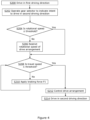
- step S200 the working machine 10 is driven in a first driving direction (i.e. forward or reverse).
- step S202 the operator of the working machine 10 operates the drive selector 50 to select a new, or second, driving direction.
- step S204 the control system 42 determines whether the determined rotational speed of the drive arrangement 36 is less than a predetermined rotational speed threshold.
- step S206 the control system 42 sends a signal to the drive arrangement 36 to control or restrict the rotational speed of the drive arrangement 36. This can be used to reduce the rotational speed of the drive arrangement 36 so as to be less than the predetermined rotational speed threshold.
- step S208 the control system 42 determined whether the determined speed of travel of the working machine 10 is less than a predetermined travel speed threshold.
- step 210 the control system 42 actuates the braking system 32 to apply the braking force F1 to the ground-engaging propulsion structure 16, 18.
- the braking force F1 may be based on the determined speed of travel and/or the rotational speed of the drive arrangement, as previously discussed. The braking force F1 may be applied until the speed of travel is less than or equal to the predetermined travel speed threshold, at which point the control system 42 ceases actuating the braking system 32.
- step S212 the control system 42 sends a signal to the drive arrangement 36 to provide motive power to the ground-engaging propulsion structure 16, 18 to move the working machine 10 in the new, or second, travel direction.
- step 214 the working machine 10 is driven in the second driving direction.
- steps S204, S206, S208, S210 and S212 may be performed in parallel, i.e. simultaneously.
- steps S208 and S210 may be performed before steps S204 and S206.
- the method may not include steps S204 and S206.
Landscapes
- Engineering & Computer Science (AREA)
- Transportation (AREA)
- Mechanical Engineering (AREA)
- Chemical & Material Sciences (AREA)
- Combustion & Propulsion (AREA)
- Automation & Control Theory (AREA)
- Mining & Mineral Resources (AREA)
- Civil Engineering (AREA)
- General Engineering & Computer Science (AREA)
- Structural Engineering (AREA)
- Regulating Braking Force (AREA)
- Operation Control Of Excavators (AREA)
Abstract
Description
- The present teachings relate to a working machine and a method for operating a working machine.
- Off-highway vehicles or working machines are for example those used in construction industries configured to transport loads over a surface (e.g. backhoe loaders, slew excavators, telescopic handlers, forklifts, skid-steer loaders etc.). These working machines typically have a body supported by a ground-engaging propulsion structure such as front and rear wheels, or a pair of endless tracks. To propel the working machine, a drive arrangement, including for example a transmission and a prime mover such as an internal combustion engine or electric motor, provides motive power to the ground-engaging propulsion structure. Working machines typically have a working arm pivotally mounted to the body of the machine, and a working implement, such as a bucket or a grabber, attached to the end of the arm via a coupling device. Attachment of the working implement enables the working machine to perform a variety of tasks on a work site.
- Some of these tasks involve changing the driving direction of the machine (i.e. from forward to reverse, or from reverse to forward) many times; for example when the machine is used for loading or unloading. To change the driving direction of a working machine, it is common for the operator to brake the working machine and to select an intended driving direction of the working machine via a gear selector. When a new intended driving direction is selected whilst the working machine is still in motion, the drive arrangement applies a torque to the ground-engaging propulsion structure, which acts to decelerate the working machine until stationary, before moving the working machine in the new intended driving direction.
- A problem with such a direction changing process is that it causes significant stresses to act on the drive arrangement, which can reduce the lifetime of the drive arrangement. Moreover, it has been found that using the drive arrangement primarily to decelerate a working machine during a change in driving direction can cause the machine to jolt on initiation of the direction changing process.
-
US2004/0180753 describes a running control device for an industrial vehicle which generates no speed change shock when the traveling direction is switched to the opposite direction by the forward-reverse selection member during the running of the vehicle. The running control device comprises a forward-reverse selected direction detection sensor which detects the selected traveling direction, a transmission which has a forward clutch and a reverse clutch that switch the traveling direction between the forward direction and reverse direction, and which transmits the driving torque of the engine to the driving wheels via the clutches, a brake which applies braking to the vehicle, a vehicle speed sensor which detects the vehicle speed, and a controller which gradually decelerates the vehicle by means of the brake when the selected traveling direction that has been detected is switched, and controls the engaging force of the forward or reverse clutch corresponding to the selected traveling direction and the braking force of the brake before the detected vehicle speed reaches zero, thus controlling the deceleration torque and acceleration torque so that the fluctuation in the acceleration around the point of time at which the traveling direction is reversed is weakened. - The present teachings seek to overcome or at least mitigate one or more problems associated with the prior art.
- The present invention provides a working machine and a method for changing the driving direction of a working machine according to the appended claims.
- A first aspect of the teachings provides a working machine comprising: a body; a ground-engaging propulsion structure supporting the body; a drive arrangement configured to provide motive power to the ground engaging propulsion structure; a braking system actuatable to apply a braking force to the ground engaging propulsion structure; a control system; and a sensor assembly configured to determine an output of the drive arrangement and to provide an output to the control system, wherein the control system is configured to apply a first braking force to the ground engaging propulsion structure that is based on the determined output of the drive arrangement.
- Advantageously, the configuration of the braking system, control system and sensor assembly enables automated braking of the working machine based on a determined output of the drive arrangement, which may simplify control of the working machine.
- The working machine may comprise a forward-neutral- reverse drive selector to select an intended driving direction of the working machine. The control system may be configured to actuate the braking system in response to an input from the drive selector selecting a new intended driving direction of the working machine.
- Advantageously, actuating the braking system when a new intended driving direction is indicated via the drive director (i.e. via the forward/neutral/reverse (FNR) selector) enables the working machine to be decelerated automatically via the braking system instead of using the transmission to effect deceleration of the working machine. By using the braking system instead of the transmission, the working machine can be decelerated in a smooth manner, which may improve the driving experience of the operator of the working machine. Moreover, by using the braking system, less stress may be imparted onto the transmission during a direction change, which may help to increase the lifespan of the components of the transmission
- The control system may be configured to control or restrict a rotational speed of the drive arrangement in response to an input from the drive selector selecting a new intended driving direction of the working machine.
- Advantageously, restricting a rotational speed of the drive arrangement when a new driving direction is indicated may help to reduce the travel speed of the working machine and enable smoother gear changes during a direction change.
- The control system may be configured such that the first braking force applied to the ground engaging propulsion structure is proportional to the determined speed of travel of the working machine or rotational speed of the drive arrangement.
- Advantageously, applying a braking force which is proportional (i.e. directly proportional or inversely proportional) to the speed of travel or rotational speed of the drive arrangement may help to ensure the working machine is decelerated smoothly by inhibiting jolting of the working machine.
- The control system may be configured such that the first braking force applied to the ground engaging propulsion structure is substantially constant.
- The output of the drive arrangement may be determined through one or more of: a speed of travel of the working machine; a rotational speed of the drive arrangement; a torque output of the drive arrangement; and/or torque within a transmission of the drive arrangement.
- The control system may be configured to apply the first braking force to the ground engaging propulsion structure when a rotational speed of the drive arrangement is below a pre-determined threshold.
- Applying a braking force when the rotational speed of the drive arrangement is below a pre-determined threshold may help to decelerate the working machine automatically when the operator has released a drive pedal of the working machine.
- The working machine may comprise a forward-neutral-reverse drive selector to select an intended driving direction of the working machine. The control system may be configured to apply the first braking force to the ground engaging propulsion structure in response to a rotational speed of the drive arrangement being below a pre-determined threshold only when the working machine is in neutral.
- The control system may be configured to apply the first braking force to the ground engaging propulsion structure when a speed of travel of the working machine is below a pre-determined threshold.
- Applying a braking force when the speed of travel of the working machine is below a first pre-determined speed threshold may help to automatically decelerate the working machine to stationary when initially travelling at low speed, and subsequently keep the working machine stationary, without the operator needing to actuate the braking system manually.
- The working machine may comprise a forward-neutral-reverse drive selector to select an intended driving direction of the working machine. The control system may be configured to apply the first braking force to the ground engaging propulsion structure in response to a speed of travel of the working machine being below a pre-determined threshold only when the working machine is in neutral.
- The braking system may be a hydraulic braking system actuated by hydraulic fluid pressure, and wherein the hydraulic fluid pressure applied to provide the first braking force is proportional to the determined speed of travel or rotational speed of the drive arrangement.
- Advantageously, the hydraulic braking system may use pressurised hydraulic fluid from a hydraulic fluid system of the working machine to enable the control system to automatically actuate the brakes. Applying a hydraulic fluid pressure that is proportional to the determined speed of travel and/or rotational speed of the drive arrangement, may help to ensure that the working machine decelerates smoothly.
- The control system may be configured to adjust the hydraulic fluid pressure by controlling a position of a valve, e.g. a solenoid valve, of the braking system.
- Controlling a valve to adjust the hydraulic fluid pressure enables accurate and robust control of brake actuation by the control system.
- The braking system may be a hydraulic braking system that is actuated by hydraulic fluid pressure and comprises at least one hydraulic power brake to apply a braking force to the ground engaging propulsion structure.
- The control system may be configured to actuate the braking system such that the working machine is decelerated at a predetermined rate.
- Decelerating the working machine at a predetermined rate may help to ensure that the working machine is decelerated in a smooth fashion.
- The magnitude of the first braking force may be based on one or more of: the speed of travel of the working machine; a rotational speed of the drive arrangement; the mass of the machine; a load carried by the working machine; and/or the position of the arm relative to the body.
- The control system may be configured to actuate the braking system such that the first braking force applied increases as the speed of travel of the working machine decreases.
- Increasing the applied first braking force as the speed of travel decreases may help to ensure that the working machine is decelerated in a smooth fashion, for example, by inhibiting jolting of the working machine.
- The control system may be configured to actuate the braking system such that the first braking force applied is inversely proportional to the speed of travel of the working machine.
- The control system may be configured to actuate the braking system such that the first braking force applied decreases as the speed of travel of the working machine decreases.
- Decreasing the applied first braking force as the speed of travel decreases may help to ensure that the working machine is decelerated in a smooth fashion, for example, by inhibiting jolting of the working machine.
- The control system may be configured to actuate the braking system such that the first braking force applied is proportional to the speed of travel of the working machine.
- The working machine may comprise a brake pedal for operation by an operator, wherein the brake pedal may be configured to actuate the braking system to apply a second braking force based on a position of the brake pedal relative to a rest position of the brake pedal.
- The brake pedal may enable the operator of the working machine to actuate the braking system manually, for example, during routine operation and/or in an emergency.
- The braking system may be configured such that, when first and second braking forces are being applied simultaneously, the greater of the first and second braking forces is applied to the ground engaging propulsion structure.
- Applying the greater of the first and second braking forces may enable the brake control input device to override the control system when the operator of the working machine wishes to apply a greater braking force than that implemented by the control system. This may improve the safe operation of the working machine since it may enable the operator to rapidly decelerate the working machine in an emergency for example.
- The braking system may be a hydraulic braking system actuated by hydraulic fluid pressure, and wherein the braking system comprises a shuttle valve comprising first and second inlets arranged to receive hydraulic fluid associated with the first and second braking forces and comprises an outlet to transmit hydraulic fluid to actuate the braking system.
- The arrangement of the shuttle valve provides a robust and effective means to enable the brake pedal to override the control system when desired, with minimal moving parts and requiring no electrical power.
- The working machine may comprise an inclination sensor configured to determine an inclination of the working machine. The control system may be configured to actuate the braking system to apply the first braking force when an inclination of the working machine is above a pre-determined inclination threshold and the speed of travel of the working machine is less than or equal to a pre-determined travel speed threshold.
- Applying a braking force when an inclination of the working machine is above a pre-determined inclination threshold and the speed of travel of the working machine is below a second pre-determined speed threshold may help to keep a working machine stationary when on an incline, such as a hill, without the operator needing to actuate the braking system manually.
- A second aspect of the teachings provides for a method for changing the driving direction of the working machine of the first aspect, the method comprising the steps of: selecting a new intended driving direction via a drive selector; and applying the first braking force to the ground engaging propulsion structure via the braking system based on an output of the drive arrangement.
- A third aspect of the teachings provides for a method for operating the working machine of the first aspect, the method comprising the steps of: determining whether the speed of travel of the working machine is below a pre-determined threshold and/or whether a rotational speed of the drive arrangement is less than pre-determined threshold; and applying the first braking force to the ground engaging propulsion structure via the braking system when the determined speed of travel of the working machine is less than the pre-determined threshold or when the determined rotational speed of the drive arrangement is less than the pre-determined threshold.
- Embodiments are now disclosed by way of example only with reference to the drawings, in which:
-
Figure 1 is a side view of a working machine according to an embodiment; -
Figure 2 is a block diagram of components of the working machine ofFigure 1 ; -
Figure 3 is a block diagram of a braking system of the working machine ofFigure 1 ; and -
Figure 4 is a flowchart of a method for changing the driving direction of the working machine ofFigure 1 . - Referring to
Figures 1 to 3 , a workingmachine 10 is illustrated. The workingmachine 10 may be considered to be a load handling machine. In this embodiment, the workingmachine 10 is a telescopic handler. In other embodiments the workingmachine 10 may be a rotating telescopic handler, a forklift, an excavator, a skid-steer loader, a compact track loader, a wheel loader, a telescopic wheel loader, or a tractor, for example. Such working machines may be denoted as off-highway vehicles or as non-road mobile machinery. - The working
machine 10 includes abody 12. Thebody 12 may include, for example, an operator'scab 14 from which an operator can operate themachine 10. Theoperator cab 14 may be mounted on thebody 12 so as to be offset from a centre of the body. Although in alternative arrangements, thecab 14 may be substantially central. Thebody 12 includes anundercarriage 13 or chassis, and asuperstructure 15. Thesuperstructure 15 is rotatable (e.g. about a substantially vertical axis) relative to theundercarriage 13. Put another way, the superstructure may be rotatable relative to the ground engaging propulsion structure. In the illustrated arrangement, theoperator cab 14 is mounted onto thesuperstructure 15. - The working
machine 10 has a ground engaging propulsion arrangement. The ground engaging propulsion arrangement or structure supports thebody 12. The ground engaging propulsion structure includes a first, or front, axle A1 and a second, or rear, axle A2, each axle being coupled to a pair ofwheels - The working
machine 10 includes adrive arrangement 36 configured to provide motive power to the ground engagingpropulsion structure machine 10 over a surface. Thedrive arrangement 36 includes aprimer mover 38 and atransmission 40. Theprime mover 38 may be an internal combustion engine, an electric motor, or may be a hybrid comprising both an internal combustion engine, an electric motor. Thedrive arrangement 36 is configured to provide motive power to the ground-engagingpropulsion structure prime mover 38 via thetransmission 40. - A working
arm 20 is pivotally connected to thebody 12. In the arrangement shown, the workingarm 20 is pivotally mounted to thesuperstructure 15. The workingarm 20 is connected to thebody 12 by amount 22 proximate a first end, or proximal end, of the workingarm 20. The workingarm 20 can be moved with respect to thebody 12 and the movement is preferably, at least in part, rotational movement about themount 22. The rotational movement is about a substantially transverse axis of themachine 10. Rotational movement of the workingarm 20 with respect to thebody 12 is, in an embodiment, achieved by use of at least one lifting actuator (not shown) coupled between thearm 20 and thebody 12. - The working
arm 20 may be a telescopic arm, having afirst section 26 connected to themount 22 and asecond section 28 which is telescopically fitted to thefirst section 26. In this embodiment, thesecond section 28 of the workingarm 20 is telescopically moveable with respect to thefirst section 26 such that the workingarm 20 can be extended and retracted. Movement of thesecond section 28 with respect to thefirst section 26 of the workingarm 20 may be achieved by use of an extension actuator (not shown), for example a double acting hydraulic linear actuator, an electric linear actuator, a telescopic extension ram, multiple extension rams, and/or a chain and pulley system. As will be appreciated, the workingarm 20 may include a plurality of sections, for example two, three, four or more sections. Each arm section may be telescopically fitted to at least one other section, and an actuator may be provided therebetween. In alternative arrangements, the workingarm 20 may not be telescopic and may include a first arm pivotally mounted to themount 22. In such arrangements, the workingarm 20 may also include a second arm pivotally mounted to the first arm. - A working implement is mounted to a second, or distal, end 21 of the working
arm 20. In the illustrated arrangement, the working implement includes acarriage 24 including a pair of spaced apartforks 30 mounted thereto. In alternative arrangements, it will be appreciated that any suitable working implement may be mounted to the workingarm 20 to suit the application. In such alternative arrangements, the working implement may be a bucket, a shovel, or a basket, for example. - The working
machine 10 includes abraking system 32 actuatable to apply a first braking force to thepropulsion structure - The working
machine 10 includes asensor assembly 34 configured to determine an output of thedrive arrangement 36. In the arrangement shown, thesensor assembly 34 is configured to determine an output of thedrive arrangement 36 in the form of a speed of travel of the workingmachine 10 and/or a rotational speed of thedrive arrangement 36 and to provide an output to acontrol system 42. It will be appreciated that the output of thedrive arrangement 36 may be based upon a torque output of theprime mover 38, torque within thetransmission 40 or any other suitable output from theprime mover 38. Thecontrol system 42 is configured such that the first braking force applied to thepropulsion structure prime mover 38. - The
sensor assembly 34 includes arotational speed sensor 44 configured to determine a rotational speed of thedrive arrangement 36. In embodiments in which theprime mover 38 is an internal combustion engine, the rotational speed determined by therotational speed sensor 44 may correspond to a rotational speed of the engine's crankshaft. In embodiments in which theprime mover 38 is an electric motor, the rotational speed determined by therotational speed sensor 44 may correspond to a rotational speed of the rotor and/or output shaft of the motor. Alternatively, the rotational speed determined by therotational speed sensor 44 may correspond to a rotational speed of thetransmission 40; e.g. a rotational speed of an input shaft to a gearbox of thetransmission 40. Thesensor assembly 34 includes atravel speed sensor 46 configured to determine a speed of travel of the workingmachine 10. Thetravel speed sensor 46 may determine the travel speed of the workingmachine 10 via any suitable means such as via sensing of the rotational speed of thewheels control system 42 is configured such that the first braking force applied to thepropulsion structure - The working
machine 10 includes control inputs to control operation of the workingmachine 10. The workingmachine 10 includes adrive selector 50. The drive selector is a forward/neutral/reverse (FNR)selector 50. Thedrive selector 50 engages drive in a selected direction, or selects a neutral gear. Thedrive selector 50 is configured to be operated by an operator of the workingmachine 10 to indicate an intended driving direction of the workingmachine 10, i.e. forward or reverse. Thedrive selector 50 may be located within thecab 14. - In a first mode of operation, the
control system 42 is configured to control/actuate thebraking system 32 to apply a braking force F1 to the ground-engagingpropulsion structure drive selector 50 indicates a new intended driving direction of the workingmachine 10. Put another way, thecontrol system 42 is configured to control/actuate thebraking system 32 to apply a braking force F1 to the ground-engagingpropulsion structure drive selector 50 has been operated to indicate an intended change in driving direction, for example, from forward to reverse, or from reverse to forward. - In the first mode of operation, the
control system 42 may be configured to actuate thebraking system 32 such that the braking force F1 is proportional (i.e. directly proportional or inversely proportional) to the determined output of thedrive arrangement 36. Put another way, thecontrol system 42 is configured to actuate thebraking system 32 such that the braking force F1 is proportional (i.e. directly proportional or inversely proportional) to the determined speed of travel or the determined rotational speed of thedrive arrangement 36. Alternatively, in the first mode of operation, the braking force F1 may be substantially constant, and thecontrol system 42 is configured to apply and remove the braking force F1. - In the first mode of operation, the
control system 42 may be configured such that the braking force F1 applied to the ground-engagingpropulsion structure drive arrangement 36 by thesensor assembly 34, as has been discussed above. Put another way, in the first mode of operation, thecontrol system 42 may be configured such that the braking force F1 applied to the ground-engagingpropulsion structure machine 10; a rotational speed of thedrive arrangement 36; a torque output of theprime mover 38; a torque within thetransmission 40; or any other suitable output from theprime mover 38. - In the first mode of operation, the
control system 42 may be configured to control thedrive arrangement 36 when the input from thedrive selector 50 indicates a new intended driving direction of the workingmachine 10. Put another way, thecontrol system 42 may be configured to control, limit or restrict a rotational speed of the drive arrangement 36 (i.e. the prime mover 38) when the input from thedrive selector 50 indicates a new intended driving direction of the workingmachine 10. Thecontrol system 42 monitors the rotational speed of thedrive arrangement 36 via the input from therotational speed sensor 44. Thecontrol system 42 may send a signal (e.g. a TSC1 signal) to a controller of theprime mover 38 to reduce the rotational speed of theprime mover 38 such that the rotational speed is less than or equal to a first predetermined rotational speed threshold in response to the input from thedrive selector 50 indicating a new intended driving direction. Thecontrol system 42 may be configured to control thedrive arrangement 36 such that the torque supplied from thedrive arrangement 36 to the ground-engaging propulsion structure corresponds to the intended driving direction. Thecontrol system 42 may send a signal to a controller of a gearbox of thetransmission 40 to change gear in response to an operation of thedrive selector 50 indicating a new intended driving direction of the workingmachine 10. In embodiments where theprime mover 38 is in the form of an electric motor, thecontrol system 42 may send a signal to a controller of theprime mover 38 to provide a torque to the ground-engaging propulsion structure which corresponds to the intended driving direction. - The working
machine 10 includes abrake pedal 52. Thebraking system 32 is configured to apply a braking force to thewheels braking system 32 is configured such that it is actuated by thebrake pedal 52 to apply the braking force to the ground engagingpropulsion structure braking system 32 is a hydraulic braking system that is actuated by hydraulic fluid pressure. Thebrake pedal 52 supplies fluid tobrakes 56 at one or more of thewheels brake pedal 52 is configured to be operated by an operator of the workingmachine 10, and may be located in thecab 14. - The
control system 42 is configured to actuate thebraking system 32 to apply a first braking force to the ground-engagingpropulsion structure brake pedal 52 is configured to actuate thebraking system 32 to apply a second braking force to the ground-engaging propulsion structure, where the second braking force applied is based on a position of thebrake pedal 52 relative to a rest position of thebrake pedal 52. Thebraking system 32 is configured such that when thecontrol system 42 actuates thebraking system 32 to apply the first braking force to the ground-engaging propulsion structure, and thebrake pedal 52 is operated to actuate thebraking system 32 to apply the second braking force to the ground-engaging propulsion structure simultaneously, the greater of the first and second braking forces is applied to the ground engagingpropulsion structure - The
braking system 32 includes ahydraulic brake 56. It will be appreciated that eachwheel brake 56 to apply a braking force thereto. Thebraking system 32 includes acontrol valve 60. Thecontrol system 42 is configured to adjust a hydraulic pressure by controlling a position of thecontrol valve 60. As such, the pressure of the hydraulic fluid supplied to thebraking system 32 can be controlled by thecontrol system 42. In the illustrated, thecontrol valve 60 is a solenoid-controlled valve, and the signal sent from thecontrol system 42 to thecontrol valve 60 corresponds to an electrical current to be supplied to the solenoid. - The
braking system 32 includes ashuttle valve 58. Thehydraulic brake 56 is in fluid communication with anoutlet 58a of theshuttle valve 58. In this way, thehydraulic brake 56 is actuated via hydraulic fluid transmitted from theoutlet 58a of theshuttle valve 58 to thehydraulic brake 56. - The
shuttle valve 58 includes afirst inlet 58b configured to receive hydraulic fluid in response to an output from the control system 42 (i.e. via the control valve 60). When thecontrol system 42 actuates thebraking system 32 to apply the first braking force to the ground-engagingpropulsion structure control valve 60, thefirst inlet 58b of theshuttle valve 58 receives hydraulic fluid at a first pressure corresponding to the first braking force. Theshuttle valve 58 includes asecond inlet 58c configured to receive hydraulic fluid in response to depression of thebrake pedal 52. When thebrake pedal 52 is operated to actuate thebraking system 32 to apply the second braking force to thebraking system 32, the second inlet 58v of theshuttle valve 58 receives hydraulic fluid at a second pressure corresponding to the second braking force. - The
shuttle valve 58 is configured such that hydraulic fluid exiting theoutlet 58a is a pressure equal to the greater of the two hydraulic fluid flows. Thus, when thecontrol system 42 actuates thebraking system 32 to apply the first braking force and thebrake pedal 52 actuates thebraking system 32 to apply the second braking force simultaneously, hydraulic fluid is transmitted from theoutlet 58a of theshuttle valve 58 to thehydraulic brake 56 at a pressure corresponding to the greater of the first braking force and the second braking force. Put another way, thehydraulic brake 56 is actuated to apply the greater of the first and second braking forces to the ground-engagingpropulsion structure machine 10 to override thecontrol system 42 in order to apply a large braking force to the ground-engaging propulsion structure than that implemented by thecontrol system 42. - In
Figure 3 , only onehydraulic brake 56 is shown. However, the workingmachine 10 may include two or morehydraulic brakes 56, for example, three or more, or four or morehydraulic brakes 56, where eachhydraulic brake 56 is in fluid communication with theoutlet 58a of theshuttle valve 58. In alternative embodiments, thebraking system 32 may be a pneumatic, an electronic, or a hybrid braking system. For example, thebraking system 32 may be an electronic braking system including an electronically actuated brake, which may be actuated by both the control system and the brake pedal to apply a braking force to the ground-engaging propulsion structure. - In a second mode of operation, the
control system 42 is configured to apply a braking force F2 to the ground engagingpropulsion structure drive arrangement 36 is below a pre-determined threshold and/or when a speed of travel of the workingmachine 10 is below a pre-determined threshold. - In the second mode of operation, it will be appreciated that the braking force applied may be a substantially constant braking force. Alternatively, the
control system 42 may be configured such that the braking force applied to the ground-engaging propulsion structure16, 18 is based on an output of thedrive arrangement 36. - In such arrangements, the
control system 42 may be configured such that the braking force F2 applied to the ground-engagingpropulsion structure drive arrangement 36 by thesensor assembly 34, such as one or more of: a speed of travel of the workingmachine 10; a rotational speed of thedrive arrangement 36; a torque output of theprime mover 38; a torque within thetransmission 40; or any other suitable output from theprime mover 38. In the second mode of operation, thecontrol system 42 may be configured such that the braking force F2 applied to the ground-engagingpropulsion structure machine 10; a rotational speed of thedrive arrangement 36; a torque output of theprime mover 38; a torque within thetransmission 40; or any other suitable output from theprime mover 38. - In the second mode of operation, the
control system 42 may only apply the braking force to the ground engagingpropulsion structure machine 10 is requesting to stop the workingmachine 10. It may be determined that an operator of the workingmachine 10 is requesting to stop the workingmachine 10 when the drive selector is placed in neutral and/or when the operator has released a drive/accelerator pedal of the workingmachine 10. Applying a braking force when the speed of travel of the workingmachine 10 is below a pre-determined speed threshold and/or when a rotational speed of thedrive arrangement 36 is below a pre-determined threshold helps to automatically bring the workingmachine 10 to a stop when initially travelling at low speed and requesting to stop, without the operator needing to actuate thebraking system 32 manually. It will be appreciated that the braking force applied may differ between when an operator lifts off the throttle, but remains with forward or reverse drive selected, and when the drive selector is placed in neutral. - The
sensor assembly 34 may include aninclination sensor 48. Theinclination sensor 48 is configured to determine an angle of inclination of the workingmachine 10. Theinclination sensor 48 provides an output of the determined inclination angle to thecontrol system 42. In arrangements where the workingmachine 10 includes theinclination sensor 48, thecontrol system 42 is configured, in a third mode of operation, to actuate thebraking system 32 to apply a braking force when an inclination of the workingmachine 10 is above a pre-determined inclination threshold. In the third mode of operation, thecontrol system 42 may be configured such that it only applies a braking force to the ground engagingpropulsion structure machine 10 is less than or equal to a pre-determined travel speed threshold. In the third mode of operation, thecontrol system 42 may be configured such that it only applies a braking force to the ground engagingpropulsion structure machine 10 is requesting to stop the workingmachine 10. It may be determined that an operator of the workingmachine 10 is requesting to stop the workingmachine 10 when the drive selector is placed in neutral and/or when the operator has released a drive/accelerator pedal of the workingmachine 10. - In the third mode of operation, the braking force applied may be a substantially constant braking force. Alternatively, the
control system 42 may be configured such that the braking force applied to the ground-engagingpropulsion structure drive arrangement 36, a torque of thedrive arrangement 36, etc.), in a similar manner as has been described above, and/or may be based on the angle of inclination detected by theinclination sensor 48. - In one arrangement, the
control system 42 is configured to actuate thebraking system 32 such that the braking force F1 increases as the determined speed of travel decreases. For example, thecontrol system 42 may be configured to actuate thebraking system 32 such that the braking force F1 is inversely proportional to the determined speed of travel. Controlling the braking force F1 such that it increases as the determined speed of travel reduces helps to ensure that the workingmachine 10 is decelerated smoothly such that jolting of the workingmachine 10 at the point when the brakes are applied is reduced. - In another arrangement, the
control system 42 is configured to actuate thebraking system 32 such that the braking force F1 decreases as the determined speed of travel decreases. For example, thecontrol system 42 may be configured to actuate thebraking system 32 such that the braking force F1 is proportional to the determined speed of travel. Controlling the braking force F1 such that it decreases as the determined speed of travel reduces helps to ensure that the workingmachine 10 is decelerated smoothly to a stop such that jolting of the workingmachine 10 when the machine comes to a standstill is reduced. - The
control system 42 may be configured to actuate thebraking system 32 such that the braking force F1 applied to the ground-engaging propulsion structure decelerates the workingmachine 10 at a predetermined rate, i.e. at a predetermined rate of deceleration or at a predetermined jerk. Actuation of the braking system 32 (i.e. the magnitude of the first braking force) may be based on one or more of: the determined speed of travel of the workingmachine 10; a rotational speed of thedrive arrangement 36; the mass of the machine; a load carried by the workingmachine 10; or the position (i.e. inclination and extension) of thearm 20 relative to thebody 12. - Although not illustrated, it will be appreciated that the working
machine 10 may be provided with an operator input so as to enable the operator to manually enable and disable thecontrol system 42, or to manually enable and disable one or more of the features of thecontrol system 42 discussed above. - Although not illustrated, it will be appreciated that the
sensor assembly 34 may be provided with a terrain sensor configured to determine characteristic of the ground over which the workingmachine 10 is travelling. In such arrangements, it will be understood that the braking force applied in each of the described modes of operation may be based on the characteristics of the ground determined by the terrain sensor. - The working
machine 10 may be configured to indicate to an operator that thecontrol system 42 is actuating thebraking system 32. The working machine may be provided with an indicator, such as an audio and/or visual indicator, and thecontrol system 42 may be configured to activate the indicator when it actuates thebraking system 32. The workingmachine 10 may be configured to provide a tactile indicator to an operator that thecontrol system 42 is actuating thebraking system 32, for example this may be done by changing the resistance in thebrake pedal 52. - With reference to
Figure 4 , a method for changing the driving direction of the workingmachine 10 will be described in the following. - In step S200, the working
machine 10 is driven in a first driving direction (i.e. forward or reverse). In step S202, the operator of the workingmachine 10 operates thedrive selector 50 to select a new, or second, driving direction. In step S204, thecontrol system 42 determines whether the determined rotational speed of thedrive arrangement 36 is less than a predetermined rotational speed threshold. - If the determined rotational speed is greater than the predetermined rotational speed threshold ('No'), the method moves to step 206. In step S206, the
control system 42 sends a signal to thedrive arrangement 36 to control or restrict the rotational speed of thedrive arrangement 36. This can be used to reduce the rotational speed of thedrive arrangement 36 so as to be less than the predetermined rotational speed threshold. - If the determined rotational speed is less than the predetermined rotational speed threshold ('Yes'), then the method moves to step S208. In step 208, the
control system 42 determined whether the determined speed of travel of the workingmachine 10 is less than a predetermined travel speed threshold. - If the determined speed of travel is greater than the predetermined travel speed threshold, the method moves to step 210. In step 210, the
control system 42 actuates thebraking system 32 to apply the braking force F1 to the ground-engagingpropulsion structure control system 42 ceases actuating thebraking system 32. - If the
control system 42 determines that the determined speed of travel is less than or equal to the first predetermined travel speed threshold, the method moves to step S212. In step 212, thecontrol system 42 sends a signal to thedrive arrangement 36 to provide motive power to the ground-engagingpropulsion structure machine 10 in the new, or second, travel direction. In step 214, the workingmachine 10 is driven in the second driving direction. - In alternative embodiments, two or more of steps S204, S206, S208, S210 and S212 may be performed in parallel, i.e. simultaneously. In yet further alternative embodiments, steps S208 and S210 may be performed before steps S204 and S206. In yet further alternative embodiments, the method may not include steps S204 and S206.
Claims (15)
- A working machine (10) comprising:a body (12);a ground-engaging propulsion structure supporting the body;a drive arrangement (36) configured to provide motive power to the ground engaging propulsion structure;a braking system (32) actuatable to apply a braking force to the ground engaging propulsion structure;a control system (42); anda sensor assembly (34) configured to determine an output of the drive arrangement and to provide an output to the control system,wherein the control system is configured to apply a first braking force to the ground engaging propulsion structure that is based on the determined output of the drive arrangement.
- The working machine according to claim 1, comprising a forward-neutral-reverse drive selector (50) to select an intended driving direction of the working machine, wherein the control system is configured to actuate the braking system in response to an input from the drive selector selecting a new intended driving direction of the working machine and, optionally, the control system is configured to control or restrict a rotational speed of the drive arrangement in response to an input from the drive selector selecting a new intended driving direction of the working machine.
- A working machine according to any preceding claim, wherein the control system is configured such that the first braking force applied to the ground engaging propulsion structure is proportional to the determined speed of travel of the working machine or rotational speed of the drive arrangement.
- A working machine according to any one of claims 1 or 2, wherein the control system is configured such that the first braking force applied to the ground engaging propulsion structure is substantially constant.
- A working machine according to any preceding claim, wherein the output of the drive arrangement is determined through one or more of: a speed of travel of the working machine; a rotational speed of the drive arrangement; a torque output of the drive arrangement; and/or torque within a transmission of the drive arrangement.
- A working machine according to any preceding claim, wherein the control system is configured to apply the first braking force to the ground engaging propulsion structure when a rotational speed of the drive arrangement is below a pre-determined threshold, and, optionally, the working machine further comprises a forward-neutral-reverse drive selector to select an intended driving direction of the working machine and the control system is configured to apply the first braking force to the ground engaging propulsion structure in response to a rotational speed of the drive arrangement being below a pre-determined threshold only when the working machine is in neutral.
- A working machine according to any preceding claim, wherein the control system is configured to apply the first braking force to the ground engaging propulsion structure when a speed of travel of the working machine is below a pre-determined threshold, and optionally, the working machine comprises a forward-neutral-reverse drive selector to select an intended driving direction of the working machine, and the control system is configured to apply the first braking force to the ground engaging propulsion structure in response to a speed of travel of the working machine being below a pre-determined threshold only when the working machine is in neutral.
- A working machine according to any preceding claim, wherein the braking system is a hydraulic braking system actuated by hydraulic fluid pressure, and wherein the hydraulic fluid pressure applied to provide the first braking force is proportional to the determined speed of travel or rotational speed of the drive arrangement and, optionally, the control system is configured to adjust the hydraulic fluid pressure by controlling a position of a valve, e.g. a solenoid valve, of the braking system.
- A working machine according to any preceding claim, wherein the braking system is a hydraulic braking system that is actuated by hydraulic fluid pressure and comprises at least one hydraulic power brake to apply a braking force to the ground engaging propulsion structure.
- A working machine according to any preceding claim, wherein the control system is configured to actuate the braking system such that the working machine is decelerated at a predetermined rate and/or the magnitude of the first braking force is based on one or more of: the speed of travel of the working machine; a rotational speed of the drive arrangement; the mass of the machine; a load carried by the working machine; and/or the position of the arm relative to the body.
- The working machine of any preceding claim, wherein the control system is configured to actuate the braking system such that the first braking force applied increases as the speed of travel of the working machine decreases and, optionally, the control system is configured to actuate the braking system such that the first braking force applied is inversely proportional to the speed of travel of the working machine.
- The working machine of any one of claims 1 to 10, wherein the control system is configured to actuate the braking system such that the first braking force applied decreases as the speed of travel of the working machine decreases and, optionally, the control system is configured to actuate the braking system such that the first braking force applied is proportional to the speed of travel of the working machine.
- The working machine according to any preceding claim, comprising a brake pedal for operation by an operator, wherein the brake pedal is configured to actuate the braking system to apply a second braking force based on a position of the brake pedal relative to a rest position of the brake pedal and, optionally, the braking system is configured such that, when first and second braking forces are being applied simultaneously, the greater of the first and second braking forces is applied to the ground engaging propulsion structure, and optionally, wherein the braking system is a hydraulic braking system actuated by hydraulic fluid pressure and comprises a shuttle valve comprising first and second inlets arranged to receive hydraulic fluid associated with the first and second braking forces and an outlet to transmit hydraulic fluid to actuate the braking system.
- The working machine according to any preceding claim, comprising an inclination sensor configured to determine an inclination of the working machine, wherein the control system is configured to actuate the braking system to apply the first braking force when an inclination of the working machine is above a pre-determined inclination threshold and the speed of travel of the working machine is less than or equal to a pre-determined travel speed threshold.
- A method for changing the driving direction of the working machine of any preceding claim, the method comprising the steps of:determining whether the speed of travel of the working machine is below a pre-determined threshold and/or whether a rotational speed of the drive arrangement is less than pre-determined threshold; andapplying the first braking force to the ground engaging propulsion structure via the braking system when the determined speed of travel of the working machine is less than the pre-determined threshold or when the determined rotational speed of the drive arrangement is less than the pre-determined threshold.
Applications Claiming Priority (1)
| Application Number | Priority Date | Filing Date | Title |
|---|---|---|---|
| GB2115798.7A GB2612590B (en) | 2021-11-03 | 2021-11-03 | A Working Machine |
Publications (2)
| Publication Number | Publication Date |
|---|---|
| EP4177406A1 true EP4177406A1 (en) | 2023-05-10 |
| EP4177406B1 EP4177406B1 (en) | 2024-12-25 |
Family
ID=78828463
Family Applications (1)
| Application Number | Title | Priority Date | Filing Date |
|---|---|---|---|
| EP22205172.4A Active EP4177406B1 (en) | 2021-11-03 | 2022-11-02 | Working machine and method of changing the driving direction of such working machine |
Country Status (3)
| Country | Link |
|---|---|
| US (1) | US20230054611A1 (en) |
| EP (1) | EP4177406B1 (en) |
| GB (1) | GB2612590B (en) |
Citations (4)
| Publication number | Priority date | Publication date | Assignee | Title |
|---|---|---|---|---|
| EP0231393A1 (en) * | 1985-07-26 | 1987-08-12 | Kabushiki Kaisha Toyoda Jidoshokki Seisakusho | Operation controller for quickly controlling change of forward or backward direction of vehicle equipped with automatic transmission |
| US20040180753A1 (en) | 2003-03-10 | 2004-09-16 | Masayuki Takamura | Running control device for industrial vehicle |
| JP2017177984A (en) * | 2016-03-29 | 2017-10-05 | 株式会社Kcm | Working vehicle |
| KR20210119034A (en) * | 2020-03-24 | 2021-10-05 | 두산인프라코어 주식회사 | Auto parking brake system of wheel excavator by angle sensing |
Family Cites Families (10)
| Publication number | Priority date | Publication date | Assignee | Title |
|---|---|---|---|---|
| JPH09202221A (en) * | 1996-01-29 | 1997-08-05 | Komatsu Ltd | Vehicle brake control device |
| GB2315826B (en) * | 1996-07-26 | 2000-05-10 | Massey Ferguson Sa | Forward/reverse gear change system |
| JP3804358B2 (en) * | 1999-10-18 | 2006-08-02 | 株式会社豊田自動織機 | Industrial vehicle switchback control device |
| EP2466018B1 (en) * | 2010-12-17 | 2019-11-13 | Caterpillar Inc. | Closed loop drive circuit with external brake assist |
| JP5092059B1 (en) * | 2012-03-29 | 2012-12-05 | 株式会社小松製作所 | Work vehicle and control method of work vehicle |
| JP5848726B2 (en) * | 2013-05-22 | 2016-01-27 | 本田技研工業株式会社 | Brake system for vehicles |
| CN105083287B (en) * | 2015-09-28 | 2017-08-11 | 浙江吉利汽车研究院有限公司 | A kind of vehicle start householder method and device |
| JP7236917B2 (en) * | 2019-04-04 | 2023-03-10 | 株式会社小松製作所 | WORK VEHICLE, CONTROL DEVICE AND CONTROL METHOD FOR WORK VEHICLE |
| US11285948B2 (en) * | 2019-05-20 | 2022-03-29 | Caterpillar Inc. | Work machine speed control braking |
| CN112879168B (en) * | 2021-01-26 | 2022-08-30 | 三一汽车起重机械有限公司 | Engine overspeed protection control method, control device and vehicle |
-
2021
- 2021-11-03 GB GB2115798.7A patent/GB2612590B/en active Active
-
2022
- 2022-11-02 EP EP22205172.4A patent/EP4177406B1/en active Active
- 2022-11-03 US US17/980,548 patent/US20230054611A1/en not_active Abandoned
Patent Citations (4)
| Publication number | Priority date | Publication date | Assignee | Title |
|---|---|---|---|---|
| EP0231393A1 (en) * | 1985-07-26 | 1987-08-12 | Kabushiki Kaisha Toyoda Jidoshokki Seisakusho | Operation controller for quickly controlling change of forward or backward direction of vehicle equipped with automatic transmission |
| US20040180753A1 (en) | 2003-03-10 | 2004-09-16 | Masayuki Takamura | Running control device for industrial vehicle |
| JP2017177984A (en) * | 2016-03-29 | 2017-10-05 | 株式会社Kcm | Working vehicle |
| KR20210119034A (en) * | 2020-03-24 | 2021-10-05 | 두산인프라코어 주식회사 | Auto parking brake system of wheel excavator by angle sensing |
Also Published As
| Publication number | Publication date |
|---|---|
| GB202115798D0 (en) | 2021-12-15 |
| GB2612590B (en) | 2024-07-03 |
| US20230054611A1 (en) | 2023-02-23 |
| EP4177406B1 (en) | 2024-12-25 |
| GB2612590A (en) | 2023-05-10 |
Similar Documents
| Publication | Publication Date | Title |
|---|---|---|
| CN102666233B (en) | Automatic downhill speed control system | |
| EP2466018B1 (en) | Closed loop drive circuit with external brake assist | |
| JP5092059B1 (en) | Work vehicle and control method of work vehicle | |
| US7959538B2 (en) | Device and method for controlling engine and hydraulic pump of working vehicle | |
| JP5059969B2 (en) | Construction vehicle | |
| JP5503954B2 (en) | Clutch control device for work vehicle | |
| US8775034B2 (en) | Shift control system for industrial vehicle | |
| CN102365227B (en) | Fuel-saving control device for working vehicle and fuel-saving control method for working vehicle | |
| EP2244920B2 (en) | A method and system for braking a vehicle | |
| WO2013115399A1 (en) | Engine control device for work vehicle | |
| EP4212675B1 (en) | Working machine comprising a stability system | |
| JP2006521238A (en) | Power transmission system for automobile and method for controlling the power transmission system | |
| JP2023085259A (en) | Work vehicle and control method of work vehicle | |
| CN101341321A (en) | Engine control device for construction work vehicle | |
| EP3879137B1 (en) | Hydrostatic transmission for a work vehicle provided with a hill-holder system | |
| EP4177406B1 (en) | Working machine and method of changing the driving direction of such working machine | |
| EP2862834B1 (en) | Industrial vehicle | |
| US8290672B2 (en) | Method and a system for controlling a vehicle | |
| US12460385B2 (en) | Power transmission device for vehicle | |
| KR102831494B1 (en) | Brake system and control method thereof | |
| JP7523394B2 (en) | Wheel Loader | |
| JP2003341496A (en) | Travel control device for industrial vehicles | |
| JP2025154479A (en) | Work vehicles |
Legal Events
| Date | Code | Title | Description |
|---|---|---|---|
| PUAI | Public reference made under article 153(3) epc to a published international application that has entered the european phase |
Free format text: ORIGINAL CODE: 0009012 |
|
| STAA | Information on the status of an ep patent application or granted ep patent |
Free format text: STATUS: REQUEST FOR EXAMINATION WAS MADE |
|
| 17P | Request for examination filed |
Effective date: 20221102 |
|
| AK | Designated contracting states |
Kind code of ref document: A1 Designated state(s): AL AT BE BG CH CY CZ DE DK EE ES FI FR GB GR HR HU IE IS IT LI LT LU LV MC ME MK MT NL NO PL PT RO RS SE SI SK SM TR |
|
| STAA | Information on the status of an ep patent application or granted ep patent |
Free format text: STATUS: EXAMINATION IS IN PROGRESS |
|
| 17Q | First examination report despatched |
Effective date: 20240220 |
|
| GRAP | Despatch of communication of intention to grant a patent |
Free format text: ORIGINAL CODE: EPIDOSNIGR1 |
|
| STAA | Information on the status of an ep patent application or granted ep patent |
Free format text: STATUS: GRANT OF PATENT IS INTENDED |
|
| INTG | Intention to grant announced |
Effective date: 20240912 |
|
| GRAS | Grant fee paid |
Free format text: ORIGINAL CODE: EPIDOSNIGR3 |
|
| P01 | Opt-out of the competence of the unified patent court (upc) registered |
Free format text: CASE NUMBER: APP_54417/2024 Effective date: 20241002 |
|
| GRAA | (expected) grant |
Free format text: ORIGINAL CODE: 0009210 |
|
| STAA | Information on the status of an ep patent application or granted ep patent |
Free format text: STATUS: THE PATENT HAS BEEN GRANTED |
|
| AK | Designated contracting states |
Kind code of ref document: B1 Designated state(s): AL AT BE BG CH CY CZ DE DK EE ES FI FR GB GR HR HU IE IS IT LI LT LU LV MC ME MK MT NL NO PL PT RO RS SE SI SK SM TR |
|
| REG | Reference to a national code |
Ref country code: GB Ref legal event code: FG4D |
|
| REG | Reference to a national code |
Ref country code: CH Ref legal event code: EP |
|
| REG | Reference to a national code |
Ref country code: DE Ref legal event code: R096 Ref document number: 602022009072 Country of ref document: DE |
|
| REG | Reference to a national code |
Ref country code: IE Ref legal event code: FG4D |
|
| REG | Reference to a national code |
Ref country code: LT Ref legal event code: MG9D |
|
| PG25 | Lapsed in a contracting state [announced via postgrant information from national office to epo] |
Ref country code: FI Free format text: LAPSE BECAUSE OF FAILURE TO SUBMIT A TRANSLATION OF THE DESCRIPTION OR TO PAY THE FEE WITHIN THE PRESCRIBED TIME-LIMIT Effective date: 20241225 |
|
| PG25 | Lapsed in a contracting state [announced via postgrant information from national office to epo] |
Ref country code: BG Free format text: LAPSE BECAUSE OF FAILURE TO SUBMIT A TRANSLATION OF THE DESCRIPTION OR TO PAY THE FEE WITHIN THE PRESCRIBED TIME-LIMIT Effective date: 20241225 |
|
| PG25 | Lapsed in a contracting state [announced via postgrant information from national office to epo] |
Ref country code: NO Free format text: LAPSE BECAUSE OF FAILURE TO SUBMIT A TRANSLATION OF THE DESCRIPTION OR TO PAY THE FEE WITHIN THE PRESCRIBED TIME-LIMIT Effective date: 20250325 |
|
| PG25 | Lapsed in a contracting state [announced via postgrant information from national office to epo] |
Ref country code: LV Free format text: LAPSE BECAUSE OF FAILURE TO SUBMIT A TRANSLATION OF THE DESCRIPTION OR TO PAY THE FEE WITHIN THE PRESCRIBED TIME-LIMIT Effective date: 20241225 Ref country code: GR Free format text: LAPSE BECAUSE OF FAILURE TO SUBMIT A TRANSLATION OF THE DESCRIPTION OR TO PAY THE FEE WITHIN THE PRESCRIBED TIME-LIMIT Effective date: 20250326 |
|
| PG25 | Lapsed in a contracting state [announced via postgrant information from national office to epo] |
Ref country code: RS Free format text: LAPSE BECAUSE OF FAILURE TO SUBMIT A TRANSLATION OF THE DESCRIPTION OR TO PAY THE FEE WITHIN THE PRESCRIBED TIME-LIMIT Effective date: 20250325 |
|
| REG | Reference to a national code |
Ref country code: NL Ref legal event code: MP Effective date: 20241225 |
|
| PG25 | Lapsed in a contracting state [announced via postgrant information from national office to epo] |
Ref country code: NL Free format text: LAPSE BECAUSE OF FAILURE TO SUBMIT A TRANSLATION OF THE DESCRIPTION OR TO PAY THE FEE WITHIN THE PRESCRIBED TIME-LIMIT Effective date: 20241225 |
|
| REG | Reference to a national code |
Ref country code: AT Ref legal event code: MK05 Ref document number: 1754256 Country of ref document: AT Kind code of ref document: T Effective date: 20241225 |
|
| PG25 | Lapsed in a contracting state [announced via postgrant information from national office to epo] |
Ref country code: SM Free format text: LAPSE BECAUSE OF FAILURE TO SUBMIT A TRANSLATION OF THE DESCRIPTION OR TO PAY THE FEE WITHIN THE PRESCRIBED TIME-LIMIT Effective date: 20241225 |
|
| PG25 | Lapsed in a contracting state [announced via postgrant information from national office to epo] |
Ref country code: PL Free format text: LAPSE BECAUSE OF FAILURE TO SUBMIT A TRANSLATION OF THE DESCRIPTION OR TO PAY THE FEE WITHIN THE PRESCRIBED TIME-LIMIT Effective date: 20241225 |
|
| PG25 | Lapsed in a contracting state [announced via postgrant information from national office to epo] |
Ref country code: ES Free format text: LAPSE BECAUSE OF FAILURE TO SUBMIT A TRANSLATION OF THE DESCRIPTION OR TO PAY THE FEE WITHIN THE PRESCRIBED TIME-LIMIT Effective date: 20241225 |
|
| PG25 | Lapsed in a contracting state [announced via postgrant information from national office to epo] |
Ref country code: IS Free format text: LAPSE BECAUSE OF FAILURE TO SUBMIT A TRANSLATION OF THE DESCRIPTION OR TO PAY THE FEE WITHIN THE PRESCRIBED TIME-LIMIT Effective date: 20250425 |
|
| PG25 | Lapsed in a contracting state [announced via postgrant information from national office to epo] |
Ref country code: PT Free format text: LAPSE BECAUSE OF FAILURE TO SUBMIT A TRANSLATION OF THE DESCRIPTION OR TO PAY THE FEE WITHIN THE PRESCRIBED TIME-LIMIT Effective date: 20250428 |
|
| PG25 | Lapsed in a contracting state [announced via postgrant information from national office to epo] |
Ref country code: EE Free format text: LAPSE BECAUSE OF FAILURE TO SUBMIT A TRANSLATION OF THE DESCRIPTION OR TO PAY THE FEE WITHIN THE PRESCRIBED TIME-LIMIT Effective date: 20241225 |
|
| PG25 | Lapsed in a contracting state [announced via postgrant information from national office to epo] |
Ref country code: RO Free format text: LAPSE BECAUSE OF FAILURE TO SUBMIT A TRANSLATION OF THE DESCRIPTION OR TO PAY THE FEE WITHIN THE PRESCRIBED TIME-LIMIT Effective date: 20241225 Ref country code: AT Free format text: LAPSE BECAUSE OF FAILURE TO SUBMIT A TRANSLATION OF THE DESCRIPTION OR TO PAY THE FEE WITHIN THE PRESCRIBED TIME-LIMIT Effective date: 20241225 |
|
| PG25 | Lapsed in a contracting state [announced via postgrant information from national office to epo] |
Ref country code: SK Free format text: LAPSE BECAUSE OF FAILURE TO SUBMIT A TRANSLATION OF THE DESCRIPTION OR TO PAY THE FEE WITHIN THE PRESCRIBED TIME-LIMIT Effective date: 20241225 |
|
| PG25 | Lapsed in a contracting state [announced via postgrant information from national office to epo] |
Ref country code: CZ Free format text: LAPSE BECAUSE OF FAILURE TO SUBMIT A TRANSLATION OF THE DESCRIPTION OR TO PAY THE FEE WITHIN THE PRESCRIBED TIME-LIMIT Effective date: 20241225 |
|
| PG25 | Lapsed in a contracting state [announced via postgrant information from national office to epo] |
Ref country code: IT Free format text: LAPSE BECAUSE OF FAILURE TO SUBMIT A TRANSLATION OF THE DESCRIPTION OR TO PAY THE FEE WITHIN THE PRESCRIBED TIME-LIMIT Effective date: 20241225 |
|
| PG25 | Lapsed in a contracting state [announced via postgrant information from national office to epo] |
Ref country code: SE Free format text: LAPSE BECAUSE OF FAILURE TO SUBMIT A TRANSLATION OF THE DESCRIPTION OR TO PAY THE FEE WITHIN THE PRESCRIBED TIME-LIMIT Effective date: 20241225 |
|
| REG | Reference to a national code |
Ref country code: DE Ref legal event code: R097 Ref document number: 602022009072 Country of ref document: DE |
|
| PG25 | Lapsed in a contracting state [announced via postgrant information from national office to epo] |
Ref country code: DK Free format text: LAPSE BECAUSE OF FAILURE TO SUBMIT A TRANSLATION OF THE DESCRIPTION OR TO PAY THE FEE WITHIN THE PRESCRIBED TIME-LIMIT Effective date: 20241225 |
|
| PLBE | No opposition filed within time limit |
Free format text: ORIGINAL CODE: 0009261 |
|
| STAA | Information on the status of an ep patent application or granted ep patent |
Free format text: STATUS: NO OPPOSITION FILED WITHIN TIME LIMIT |
|
| 26N | No opposition filed |
Effective date: 20250926 |
|
| PGFP | Annual fee paid to national office [announced via postgrant information from national office to epo] |
Ref country code: DE Payment date: 20251119 Year of fee payment: 4 |
|
| PGFP | Annual fee paid to national office [announced via postgrant information from national office to epo] |
Ref country code: FR Payment date: 20251126 Year of fee payment: 4 |
|
| PG25 | Lapsed in a contracting state [announced via postgrant information from national office to epo] |
Ref country code: HR Free format text: LAPSE BECAUSE OF FAILURE TO SUBMIT A TRANSLATION OF THE DESCRIPTION OR TO PAY THE FEE WITHIN THE PRESCRIBED TIME-LIMIT Effective date: 20241225 |