EP4177379A1 - Porous ionomer free layered metal alloy electrocatalyst electrode - Google Patents
Porous ionomer free layered metal alloy electrocatalyst electrode Download PDFInfo
- Publication number
- EP4177379A1 EP4177379A1 EP21383006.0A EP21383006A EP4177379A1 EP 4177379 A1 EP4177379 A1 EP 4177379A1 EP 21383006 A EP21383006 A EP 21383006A EP 4177379 A1 EP4177379 A1 EP 4177379A1
- Authority
- EP
- European Patent Office
- Prior art keywords
- electrocatalyst
- layer
- electrode
- alloy
- substrate
- Prior art date
- Legal status (The legal status is an assumption and is not a legal conclusion. Google has not performed a legal analysis and makes no representation as to the accuracy of the status listed.)
- Granted
Links
Images




Classifications
-
- C—CHEMISTRY; METALLURGY
- C25—ELECTROLYTIC OR ELECTROPHORETIC PROCESSES; APPARATUS THEREFOR
- C25B—ELECTROLYTIC OR ELECTROPHORETIC PROCESSES FOR THE PRODUCTION OF COMPOUNDS OR NON-METALS; APPARATUS THEREFOR
- C25B11/00—Electrodes; Manufacture thereof not otherwise provided for
- C25B11/04—Electrodes; Manufacture thereof not otherwise provided for characterised by the material
- C25B11/051—Electrodes formed of electrocatalysts on a substrate or carrier
- C25B11/073—Electrodes formed of electrocatalysts on a substrate or carrier characterised by the electrocatalyst material
- C25B11/091—Electrodes formed of electrocatalysts on a substrate or carrier characterised by the electrocatalyst material consisting of at least one catalytic element and at least one catalytic compound; consisting of two or more catalytic elements or catalytic compounds
-
- C—CHEMISTRY; METALLURGY
- C23—COATING METALLIC MATERIAL; COATING MATERIAL WITH METALLIC MATERIAL; CHEMICAL SURFACE TREATMENT; DIFFUSION TREATMENT OF METALLIC MATERIAL; COATING BY VACUUM EVAPORATION, BY SPUTTERING, BY ION IMPLANTATION OR BY CHEMICAL VAPOUR DEPOSITION, IN GENERAL; INHIBITING CORROSION OF METALLIC MATERIAL OR INCRUSTATION IN GENERAL
- C23C—COATING METALLIC MATERIAL; COATING MATERIAL WITH METALLIC MATERIAL; SURFACE TREATMENT OF METALLIC MATERIAL BY DIFFUSION INTO THE SURFACE, BY CHEMICAL CONVERSION OR SUBSTITUTION; COATING BY VACUUM EVAPORATION, BY SPUTTERING, BY ION IMPLANTATION OR BY CHEMICAL VAPOUR DEPOSITION, IN GENERAL
- C23C14/00—Coating by vacuum evaporation, by sputtering or by ion implantation of the coating forming material
- C23C14/06—Coating by vacuum evaporation, by sputtering or by ion implantation of the coating forming material characterised by the coating material
- C23C14/14—Metallic material, boron or silicon
- C23C14/16—Metallic material, boron or silicon on metallic substrates or on substrates of boron or silicon
- C23C14/165—Metallic material, boron or silicon on metallic substrates or on substrates of boron or silicon by cathodic sputtering
-
- C—CHEMISTRY; METALLURGY
- C23—COATING METALLIC MATERIAL; COATING MATERIAL WITH METALLIC MATERIAL; CHEMICAL SURFACE TREATMENT; DIFFUSION TREATMENT OF METALLIC MATERIAL; COATING BY VACUUM EVAPORATION, BY SPUTTERING, BY ION IMPLANTATION OR BY CHEMICAL VAPOUR DEPOSITION, IN GENERAL; INHIBITING CORROSION OF METALLIC MATERIAL OR INCRUSTATION IN GENERAL
- C23C—COATING METALLIC MATERIAL; COATING MATERIAL WITH METALLIC MATERIAL; SURFACE TREATMENT OF METALLIC MATERIAL BY DIFFUSION INTO THE SURFACE, BY CHEMICAL CONVERSION OR SUBSTITUTION; COATING BY VACUUM EVAPORATION, BY SPUTTERING, BY ION IMPLANTATION OR BY CHEMICAL VAPOUR DEPOSITION, IN GENERAL
- C23C14/00—Coating by vacuum evaporation, by sputtering or by ion implantation of the coating forming material
- C23C14/06—Coating by vacuum evaporation, by sputtering or by ion implantation of the coating forming material characterised by the coating material
- C23C14/14—Metallic material, boron or silicon
- C23C14/20—Metallic material, boron or silicon on organic substrates
- C23C14/205—Metallic material, boron or silicon on organic substrates by cathodic sputtering
-
- C—CHEMISTRY; METALLURGY
- C23—COATING METALLIC MATERIAL; COATING MATERIAL WITH METALLIC MATERIAL; CHEMICAL SURFACE TREATMENT; DIFFUSION TREATMENT OF METALLIC MATERIAL; COATING BY VACUUM EVAPORATION, BY SPUTTERING, BY ION IMPLANTATION OR BY CHEMICAL VAPOUR DEPOSITION, IN GENERAL; INHIBITING CORROSION OF METALLIC MATERIAL OR INCRUSTATION IN GENERAL
- C23C—COATING METALLIC MATERIAL; COATING MATERIAL WITH METALLIC MATERIAL; SURFACE TREATMENT OF METALLIC MATERIAL BY DIFFUSION INTO THE SURFACE, BY CHEMICAL CONVERSION OR SUBSTITUTION; COATING BY VACUUM EVAPORATION, BY SPUTTERING, BY ION IMPLANTATION OR BY CHEMICAL VAPOUR DEPOSITION, IN GENERAL
- C23C14/00—Coating by vacuum evaporation, by sputtering or by ion implantation of the coating forming material
- C23C14/22—Coating by vacuum evaporation, by sputtering or by ion implantation of the coating forming material characterised by the process of coating
- C23C14/34—Sputtering
- C23C14/3407—Cathode assembly for sputtering apparatus, e.g. Target
- C23C14/3414—Metallurgical or chemical aspects of target preparation, e.g. casting, powder metallurgy
-
- C—CHEMISTRY; METALLURGY
- C25—ELECTROLYTIC OR ELECTROPHORETIC PROCESSES; APPARATUS THEREFOR
- C25B—ELECTROLYTIC OR ELECTROPHORETIC PROCESSES FOR THE PRODUCTION OF COMPOUNDS OR NON-METALS; APPARATUS THEREFOR
- C25B1/00—Electrolytic production of inorganic compounds or non-metals
- C25B1/01—Products
- C25B1/02—Hydrogen or oxygen
- C25B1/04—Hydrogen or oxygen by electrolysis of water
-
- C—CHEMISTRY; METALLURGY
- C25—ELECTROLYTIC OR ELECTROPHORETIC PROCESSES; APPARATUS THEREFOR
- C25B—ELECTROLYTIC OR ELECTROPHORETIC PROCESSES FOR THE PRODUCTION OF COMPOUNDS OR NON-METALS; APPARATUS THEREFOR
- C25B11/00—Electrodes; Manufacture thereof not otherwise provided for
- C25B11/02—Electrodes; Manufacture thereof not otherwise provided for characterised by shape or form
- C25B11/03—Electrodes; Manufacture thereof not otherwise provided for characterised by shape or form perforated or foraminous
- C25B11/031—Porous electrodes
- C25B11/032—Gas diffusion electrodes
-
- C—CHEMISTRY; METALLURGY
- C25—ELECTROLYTIC OR ELECTROPHORETIC PROCESSES; APPARATUS THEREFOR
- C25B—ELECTROLYTIC OR ELECTROPHORETIC PROCESSES FOR THE PRODUCTION OF COMPOUNDS OR NON-METALS; APPARATUS THEREFOR
- C25B11/00—Electrodes; Manufacture thereof not otherwise provided for
- C25B11/04—Electrodes; Manufacture thereof not otherwise provided for characterised by the material
- C25B11/051—Electrodes formed of electrocatalysts on a substrate or carrier
- C25B11/052—Electrodes comprising one or more electrocatalytic coatings on a substrate
-
- C—CHEMISTRY; METALLURGY
- C25—ELECTROLYTIC OR ELECTROPHORETIC PROCESSES; APPARATUS THEREFOR
- C25B—ELECTROLYTIC OR ELECTROPHORETIC PROCESSES FOR THE PRODUCTION OF COMPOUNDS OR NON-METALS; APPARATUS THEREFOR
- C25B11/00—Electrodes; Manufacture thereof not otherwise provided for
- C25B11/04—Electrodes; Manufacture thereof not otherwise provided for characterised by the material
- C25B11/051—Electrodes formed of electrocatalysts on a substrate or carrier
- C25B11/052—Electrodes comprising one or more electrocatalytic coatings on a substrate
- C25B11/053—Electrodes comprising one or more electrocatalytic coatings on a substrate characterised by multilayer electrocatalytic coatings
-
- C—CHEMISTRY; METALLURGY
- C25—ELECTROLYTIC OR ELECTROPHORETIC PROCESSES; APPARATUS THEREFOR
- C25B—ELECTROLYTIC OR ELECTROPHORETIC PROCESSES FOR THE PRODUCTION OF COMPOUNDS OR NON-METALS; APPARATUS THEREFOR
- C25B11/00—Electrodes; Manufacture thereof not otherwise provided for
- C25B11/04—Electrodes; Manufacture thereof not otherwise provided for characterised by the material
- C25B11/051—Electrodes formed of electrocatalysts on a substrate or carrier
- C25B11/055—Electrodes formed of electrocatalysts on a substrate or carrier characterised by the substrate or carrier material
-
- C—CHEMISTRY; METALLURGY
- C25—ELECTROLYTIC OR ELECTROPHORETIC PROCESSES; APPARATUS THEREFOR
- C25B—ELECTROLYTIC OR ELECTROPHORETIC PROCESSES FOR THE PRODUCTION OF COMPOUNDS OR NON-METALS; APPARATUS THEREFOR
- C25B11/00—Electrodes; Manufacture thereof not otherwise provided for
- C25B11/04—Electrodes; Manufacture thereof not otherwise provided for characterised by the material
- C25B11/051—Electrodes formed of electrocatalysts on a substrate or carrier
- C25B11/055—Electrodes formed of electrocatalysts on a substrate or carrier characterised by the substrate or carrier material
- C25B11/056—Electrodes formed of electrocatalysts on a substrate or carrier characterised by the substrate or carrier material consisting of textile or non-woven fabric
-
- C—CHEMISTRY; METALLURGY
- C25—ELECTROLYTIC OR ELECTROPHORETIC PROCESSES; APPARATUS THEREFOR
- C25B—ELECTROLYTIC OR ELECTROPHORETIC PROCESSES FOR THE PRODUCTION OF COMPOUNDS OR NON-METALS; APPARATUS THEREFOR
- C25B11/00—Electrodes; Manufacture thereof not otherwise provided for
- C25B11/04—Electrodes; Manufacture thereof not otherwise provided for characterised by the material
- C25B11/051—Electrodes formed of electrocatalysts on a substrate or carrier
- C25B11/055—Electrodes formed of electrocatalysts on a substrate or carrier characterised by the substrate or carrier material
- C25B11/057—Electrodes formed of electrocatalysts on a substrate or carrier characterised by the substrate or carrier material consisting of a single element or compound
- C25B11/061—Metal or alloy
-
- C—CHEMISTRY; METALLURGY
- C25—ELECTROLYTIC OR ELECTROPHORETIC PROCESSES; APPARATUS THEREFOR
- C25B—ELECTROLYTIC OR ELECTROPHORETIC PROCESSES FOR THE PRODUCTION OF COMPOUNDS OR NON-METALS; APPARATUS THEREFOR
- C25B11/00—Electrodes; Manufacture thereof not otherwise provided for
- C25B11/04—Electrodes; Manufacture thereof not otherwise provided for characterised by the material
- C25B11/051—Electrodes formed of electrocatalysts on a substrate or carrier
- C25B11/055—Electrodes formed of electrocatalysts on a substrate or carrier characterised by the substrate or carrier material
- C25B11/057—Electrodes formed of electrocatalysts on a substrate or carrier characterised by the substrate or carrier material consisting of a single element or compound
- C25B11/065—Carbon
-
- C—CHEMISTRY; METALLURGY
- C25—ELECTROLYTIC OR ELECTROPHORETIC PROCESSES; APPARATUS THEREFOR
- C25B—ELECTROLYTIC OR ELECTROPHORETIC PROCESSES FOR THE PRODUCTION OF COMPOUNDS OR NON-METALS; APPARATUS THEREFOR
- C25B11/00—Electrodes; Manufacture thereof not otherwise provided for
- C25B11/04—Electrodes; Manufacture thereof not otherwise provided for characterised by the material
- C25B11/051—Electrodes formed of electrocatalysts on a substrate or carrier
- C25B11/073—Electrodes formed of electrocatalysts on a substrate or carrier characterised by the electrocatalyst material
- C25B11/075—Electrodes formed of electrocatalysts on a substrate or carrier characterised by the electrocatalyst material consisting of a single catalytic element or catalytic compound
- C25B11/089—Alloys
-
- C—CHEMISTRY; METALLURGY
- C25—ELECTROLYTIC OR ELECTROPHORETIC PROCESSES; APPARATUS THEREFOR
- C25B—ELECTROLYTIC OR ELECTROPHORETIC PROCESSES FOR THE PRODUCTION OF COMPOUNDS OR NON-METALS; APPARATUS THEREFOR
- C25B9/00—Cells or assemblies of cells; Constructional parts of cells; Assemblies of constructional parts, e.g. electrode-diaphragm assemblies; Process-related cell features
- C25B9/70—Assemblies comprising two or more cells
- C25B9/73—Assemblies comprising two or more cells of the filter-press type
- C25B9/75—Assemblies comprising two or more cells of the filter-press type having bipolar electrodes
-
- C—CHEMISTRY; METALLURGY
- C25—ELECTROLYTIC OR ELECTROPHORETIC PROCESSES; APPARATUS THEREFOR
- C25B—ELECTROLYTIC OR ELECTROPHORETIC PROCESSES FOR THE PRODUCTION OF COMPOUNDS OR NON-METALS; APPARATUS THEREFOR
- C25B9/00—Cells or assemblies of cells; Constructional parts of cells; Assemblies of constructional parts, e.g. electrode-diaphragm assemblies; Process-related cell features
- C25B9/70—Assemblies comprising two or more cells
- C25B9/73—Assemblies comprising two or more cells of the filter-press type
- C25B9/77—Assemblies comprising two or more cells of the filter-press type having diaphragms
-
- Y—GENERAL TAGGING OF NEW TECHNOLOGICAL DEVELOPMENTS; GENERAL TAGGING OF CROSS-SECTIONAL TECHNOLOGIES SPANNING OVER SEVERAL SECTIONS OF THE IPC; TECHNICAL SUBJECTS COVERED BY FORMER USPC CROSS-REFERENCE ART COLLECTIONS [XRACs] AND DIGESTS
- Y02—TECHNOLOGIES OR APPLICATIONS FOR MITIGATION OR ADAPTATION AGAINST CLIMATE CHANGE
- Y02E—REDUCTION OF GREENHOUSE GAS [GHG] EMISSIONS, RELATED TO ENERGY GENERATION, TRANSMISSION OR DISTRIBUTION
- Y02E60/00—Enabling technologies; Technologies with a potential or indirect contribution to GHG emissions mitigation
- Y02E60/30—Hydrogen technology
- Y02E60/36—Hydrogen production from non-carbon containing sources, e.g. by water electrolysis
-
- Y—GENERAL TAGGING OF NEW TECHNOLOGICAL DEVELOPMENTS; GENERAL TAGGING OF CROSS-SECTIONAL TECHNOLOGIES SPANNING OVER SEVERAL SECTIONS OF THE IPC; TECHNICAL SUBJECTS COVERED BY FORMER USPC CROSS-REFERENCE ART COLLECTIONS [XRACs] AND DIGESTS
- Y02—TECHNOLOGIES OR APPLICATIONS FOR MITIGATION OR ADAPTATION AGAINST CLIMATE CHANGE
- Y02E—REDUCTION OF GREENHOUSE GAS [GHG] EMISSIONS, RELATED TO ENERGY GENERATION, TRANSMISSION OR DISTRIBUTION
- Y02E60/00—Enabling technologies; Technologies with a potential or indirect contribution to GHG emissions mitigation
- Y02E60/30—Hydrogen technology
- Y02E60/50—Fuel cells
-
- Y—GENERAL TAGGING OF NEW TECHNOLOGICAL DEVELOPMENTS; GENERAL TAGGING OF CROSS-SECTIONAL TECHNOLOGIES SPANNING OVER SEVERAL SECTIONS OF THE IPC; TECHNICAL SUBJECTS COVERED BY FORMER USPC CROSS-REFERENCE ART COLLECTIONS [XRACs] AND DIGESTS
- Y02—TECHNOLOGIES OR APPLICATIONS FOR MITIGATION OR ADAPTATION AGAINST CLIMATE CHANGE
- Y02P—CLIMATE CHANGE MITIGATION TECHNOLOGIES IN THE PRODUCTION OR PROCESSING OF GOODS
- Y02P20/00—Technologies relating to chemical industry
- Y02P20/10—Process efficiency
- Y02P20/133—Renewable energy sources, e.g. sunlight
Definitions
- the invention relates to a new kind of electrocatalyst to be incorporated as part of the electrodes, in the anode, in water electrolysers aimed for hydrogen production through the electrochemical splitting of water into oxygen and hydrogen.
- the electrocatalyst is characterized by a layered and porous structure that provides a high performance towards the oxygen evolution reaction in the absence of added ionomer.
- the object of the invention is framed in the field of energy.
- Hydrogen is a promising energy vector for a clean and sustainable energy usage for operation in domestic, transport and industrial sectors.
- most hydrogen production relies on the steam-methane (or other hydrocarbons) reforming. This procedure is responsible for emitting CO 2 to the atmosphere in un-manageable amounts.
- environmentally friendly routes e.g., electricity from renewable sources
- water electrolysis using intermittent renewable energy sources is emerging as a viable alternative, even at industrial scale, to those traditional methods for hydrogen production.
- Anion Exchange Membrane Water Electrolysis is an emerging technology for hydrogen production. It operates at low temperatures (typically up to 80oC) and has several advantages with respect to other more traditional electrolyser types as the reduction of membranes and electrocatalysts cost (e.g., in comparison with Proton Exchange Membrane Water Electrolysis typically requiring Pt group metals electrocatalysts) or the decrease of the problems associated to the formation of potassium carbonate in conventional alkaline electrolysis processes [ J.E. Park, S.Y. Kang, S.-H. Oh, J.K. Kim, M.S. Lim, C.-Y. Ahn, Y.-H. Cho, Y.-E. Sung, High-performance anion-exchange membrane water electrolysis, Electrochim. Acta. 295 (2019) 99-106 ].
- Nickel and nickel-transition metal alloy based electrocatalyst electrodes have demonstrated a high activity in basic medium both for the oxygen evolution reaction (OER) and for hydrogen evolution reaction (HER), the former being the most restrictive reaction due to its higher overpotential.
- OER oxygen evolution reaction
- HER hydrogen evolution reaction
- catalyst based on Ni alloy formulations e.g., Fe/Ni, Mo/Ni, but not restricted to these compositions
- Fe/Ni, Mo/Ni are known to decrease the OER overpotential, resulting in a highly active and low cost electrocatalyst compared with platinum metal group catalysts.
- improving the electrode performance to make AEMWE a competitive technology entails the optimization of micro-structure, porosity, amount, chemistry/composition and electrochemical surface area of the active phase of the electrocatalyst [ A.
- electrode electrocatalysts must present high electrochemical activity and stability, be cheap and have a secure supply. From an operational point of view, it is also critical to achieve a precise control over catalyst microstructure, composition, element distribution and chemical state. For practical exploitation, to reduce the cost related to the electrocatalyst load, electrocatalysts must possess a high specific activity towards the OER and HER reactions taking place in the electrolyser. These characteristics and requirements can be optimized by the usage of appropriate preparation methods.
- the most common routes to fabricate the electrodes for water electrolysis involve the incorporation of a catalyst slurry or ink into a gas diffusion layer (GDL) support.
- GDL gas diffusion layer
- an ionomer compound is also added to the slurry or ink in order to promote the diffusion of hydroxyl groups to the anode active sites where the oxidation reaction leading to the formation of oxygen will take place.
- the catalysts themselves are mostly prepared as powders following wet routes as co-precipitation, hydrothermal, sol-gel, or directly incorporated into the electrode using electrodeposition methods.
- typical steps involve the preparation of precursor solutions, precipitation processes, washings, filtrations, dryings, calcinations, and/or milling.
- a clear disadvantage of these wet routes is that they involve solvents that produce unwanted wastes and imply a high number of steps, which handicap reproducibility when scaling up the manufacture procedure of the electrocatalyst.
- ionomer function is twofold. It serves as binder to the GDL supports and it increases the number of ion transport pathways between the electrocatalyst load and the anion exchange membrane, favouring the anion diffusion capacity up to the reaction sites.
- This compound influences the gas permeability and, thanks to its charged functional groups, facilitates the exchange of water and OH - ion at the catalyst surface.
- ionomers can be also disadvantageous if, through electrostatic/covalent interactions, their charged groups occupy catalyst active sites, thus increasing the HER and OER operating overpotentials.
- ionomers may undergo chemical degradation, resulting in a deterioration of the effective catalyst-ionomer interface and, therefore, the electrochemical active surface area of the electrode available for reaction.
- the development of new catalyst formulations avoiding the use of said ionomers is therefore a clear need to ensure the long term operation of electrolyser cells.
- the present invention proposes the incorporation of layered metal alloys electrocatalyst into gas diffusion layer backings by means of magnetron sputtering in oblique angle deposition geometry (MS-OAD) in order to obtain an ionomer-free electrode.
- MS-OAD magnetron sputtering in oblique angle deposition geometry
- the resulting porous and nanostructured electrodes can be integrated in membrane electrode assemblies and, afterwards, in suitable stacks to build AEMWE electrolysers.
- a first aspect of the present invention relates to a layered electrocatalyst electrode comprising
- equivalent thickness refers to the thickness of the NiFe alloy deposited on a flat substrate in the same deposition batch that the electrocatalysts on the GDL.
- electrocatalyst layer refers to an alloy layer with a controlled composition, porosity and microstructure that is deposited onto the macroporous substrate by magnetron sputtering in an oblique angle geometry. It is the electroactive catalyst layer inducing the OER or HER reaction upon application of a polarization potential.
- the pore sizes are determined by direct quantification by Scanning Electron Microscopy pictures of the films and the pore volume measured by Kr gas adsorption isotherm. This electrocatalytic layer is arranged to be in contact with an electrolyte under operating conditions through the second surface described above.
- macroporous refers to an open pore structure with pore sizes in the range of 5-100 microns as determined by direct observation by means of scanning electron microscopy.
- the voids are defined by the arrangement of yarns or microfibers or by a sponge-like or mesh or similar structures and where the said voids have a size in the range of 5 to 100 microns.
- macroporous gas diffusion layer and current collector refers to a macroporous material that act as support of the electrocatalyst layer. It refers to the said woven-, microfiber-, mesh- or sponge- like structure of the substrates in the form of a laminate that can be made of either carbon, nickel, stainless steel or any other material stable in the basic medium where the OER takes place.
- ECSA electrochemical active surface area
- the electrocatalyst layer as used in the present invention is deposited on rough or macroporous randomly oriented surfaces as those of the typical GDLs formed by the agglomeration of microfibers or with a sponge like microstructure, but keeps the average mesoporosity, conferring a potentially high electrochemical performance to the electrocatalyst materials prepared in these conditions.
- the high porosity and high specific ECSA of the electrocatalyst layer attainable by properly controlling the deposition process are other essential conditions for an optimized performance towards OER and HER.
- the GDL macroporous materials selected must present a high electron conductivity, enable the out-diffusion of the gases (H 2 or O 2 ) from the interface between the anion exchange membrane of the AEMWE cells and the electrocatalyst layer and be highly stable in the basic operation conditions of the electrochemical cell.
- a tailored in-depth distribution of porosity and composition along the electrocatalyst layer attainable by properly controlling the deposition process are additional key features of these electrocatalyst layers.
- Another advantage of the electrodes manufactured by the incorporation of the said electrocatalyst layer onto the GDL substrates as claimed in the present invention is the absence of any appreciable degradation or delamination of the electrocatalyst layer from the GDL after use, clearly evidencing the great stability of the electrodes. Furthermore, this stability can be confirmed because no traces of Fe and/or Ni have been observed after performing an inductively coupled plasma analysis of the alkaline water solutions feeding the electrolyser after experiments.
- Electrodes prepared as described in the present invention present similar electrochemical performance than conventional electrodes prepared by wet chemical routes with, at least, one order of magnitude less active material (e.g., Ni, NiFe, etc.) than in these other cases.
- active material e.g., Ni, NiFe, etc.
- Another advantage of the proposed alloy electrodes is the control of the elemental distribution in-depth within the layer structure according to different profiles, including a homogeneous distribution, a bilayer or multilayer distribution or a smoothly variable elemental profile distribution, among others. This allows tailoring the properties of the electrocatalyst layer, for example to bring in contact with the GDL support a composition more prompt to adherence and at the external zones in contact with the electrolyte a phase composition particularly active towards the OER or HER reaction. This control has also clear advantages regarding the cost of the metals since only a few atomic layers of the most expensive elements can be deposited in the outer zones to act as effective electrocatalyst in contact with the electrolyte when said electrode is in use.
- the GDL macroporous substrate acting as backing gas diffusion layer and current collector is nickel with the form of mesh like structure, because its highest robustness against chemical degradation in basic media.
- the stoichiometry of the alloy in the electrocatalyst layer has a homogeneous composition from first surface to the second surface; or wherein the stoichiometry of the alloy in the electrocatalyst layer has a linear compositional gradient of the percent in weight of Fe in the alloy in the direction of the layer thickness from the first surface at the interface with the GDL substrate to the second surface at the outmost external zones in contact with the electrolyte.
- the stoichiometry of the NiFe alloy is adjusted to an average value between 8 % and 12% in weight of Fe in the alloy. This ratio ensures the homogeneous distribution of iron atoms within the nickel atomic lattice and provides the maximum current when operated to induce the OER.
- the NiFe alloy composition of the first surface of the electrocatalyst layer is between 0.1% and 2% in weight of Fe in the alloy, and at the second outer zone is between 10% and 20% in weight of Fe in the alloy.
- a varying profile of the porosity is achieved varying the gas plasma pressure during the MS deposition and/or the angle of deposition during MS-OAD.
- the electrocatalyst at the second surface further comprises a layer of a Ni(Fe)O x H y compound.
- Said compound leads to an enhancement of surface reactivity. This, combined with the metallic character of the bulk of the catalyst film, a feature that diminishes the electrical resistance of the electrode, further contributes to enhance the performance of the OER electrochemical process.
- Ni(Fe)O x H y compound refers to a layer of a mixed oxide-hydroxide of Fe and Ni which is deemed the active phase for the OER. This layer can be directly deposited by MS-OAD on the external surface of the NiFe electrocatalyst catalyst, but most commonly is generated from the FeNi alloy by the electrochemical cycling of the electrodes in the basic medium.
- Magnetron sputtering deposition technology is a classical physical vapour deposition procedure widely utilized in the industry for the preparation of compact layers for a large variety of applications in optics, tribology, hard coatings, etc.
- This invention claims that it is also an optimum choice for the fabrication of porous and nanostructured electrocatalyst layers suitable for their integration into highly performant AEMWE cells.
- this method when this method is utilized in an oblique angle deposition configuration (MS-OAD) and certain operation conditions, it provides nanostructured and highly porous electrocatalyst layers which, gifted with a high electrochemical active surface area, result very appropriate for their incorporation onto GDL as electrodes in AEMWE.
- the method is highly reproducible, scalable to large deposition areas, does not produce residues and works at room temperature.
- a careful adjustment of the deposition geometry and the plasma gas pressure during MS-OAD renders mesoporous nanostructured materials with a strict control of the composition, load and microstructure.
- the resulting nanostructured layer deposited onto the GDL facilitates the flow of liquid reactants (basic aqueous solution) and the release of the produced gases (H 2 , O 2 ) through the nanometric pathways existing in the catalyst deposits decorating the fibrous/macroporous GDL backing.
- Another advantage of the process of the present invention is to prepare in-depth composition variable electrocatalyst layers with a tailored composition and porosity distributions in depth.
- the target has a disc shape with a diameter size of between 50 mm and 100 mm, and wherein the pulse DC power of step (c) is between 50 W and 300 W and a frequency of between 80 and 140 kHz.
- the nickel/iron target or targets is a nickel with a shape selected from disc, circular, square, cylinder and rectangle, more preferably with circular shape with a diameter between 50 mm and 100 mm with iron strips with a width of between 1 mm and 2 mm and a thickness between 0.2 and 0.3 mm, axially wrapped on the disc surface.
- the porous electrocatalyst To achieve the expected activity of the porous electrocatalyst, it is fabricated by magnetron sputtering at oblique angles. Due to the fact that MS-OAD induces intrinsically inhomogeneous deposits on large substrates, substrate movement during deposition is mandatory to achieve homogeneous loads on substrates. There are various possibilities to achieve a homogeneous deposition.
- the experimental set-up consists of a rotatable sample holder whose axis is placed normal to the main direction of particle flux from either the magnetron heads.
- the GDL backing electrode is attached to the sample holder and continuously rotated during the deposition of the mesoporous electrocatalyst.
- the microfiber, sponge or mesh like structure of the textured substrate support becomes decorated with a mesoporosus NiFe electrocatalyst layer.
- this geometrical configuration and realization procedure renders vertically oriented mesoporous nanocolumnar structures.
- the deposition of the electrocatalyst is done in even number of steps at a fixed perpendicular orientation of the GDL substrate with respect to a sputtering target, and azimuthally turning the sample holder 180o for each deposition step.
- the substrate surface normal forms an oblique angle with respect to a perpendicular line to the target.
- This second option produces a zig-zag microstructure when deposited on flat substrates.
- the result is a nanostructured layer covering the pores surfaces at the shallow regions of the supports and a homogeneous thickness distribution of the electrocatalyst layer on the whole substrate.
- a flexible GDL backing can be attached to a cylindrical sample holder that turns continuously around its shaft axis during deposition.
- This latter configuration is compatible with roll-to-roll procedures and permits the optimization of the deposition of material onto the substrate. In these conditions, the main flow of material from the sputtered target will reach the GDL substrate at averaged local oblique geometries, thus warrantying a high mesoporosity.
- MS-OAD process can also be used to get the desired porous microstructure up to 50% of the volume of the layer as the use of slits and linear movable substrates or the twisting of substrates at giving moments of the deposition in order to homogenize the electrocatalyst layer thickness over the entire substrate.
- the use of slits serves to select depositing particles coming from the target within a certain solid angle and arriving to the substrate at an oblique angle with respect to its surface normal.
- An inconvenient of this configuration is that only a small fraction of the sputtered material coming from the target passes through the slit up to the substrate.
- a third aspect of the present invention is a membrane electrode assembly (MEA) characterized in that it comprises two electrodes, at least one of said electrode is the electrode described above in the present invention, and an anion exchange membrane.
- MEA membrane electrode assembly
- membrane electrode assembly refers to the anion exchange membrane sandwiched between an anode and a cathode, with anode/cathode consisted of GLD with corresponding deposited electrocatalyst optimised for OER/HER, respectively.
- the whole ensemble is embodied and pressed between to bipolar metal plates enabling the access of the electrolyte, generally a KOH aqueous solution with a given concentration, typically 1.0 M, and the release of the produced gases (O 2 at the anode, H 2 at the cathode)
- the MEAs operating temperature is, generally between 60 and 80 °C
- the temperature in step i) is between 60 oC and 80 oC.
- the sixth aspect of the present invention is the use of the layered electrocatalyst electrode described above in the present invention as an anode in AEMWE electrolysers.
- a NiFe bimetallic electrocatalyst electrode of the present invention was prepared at room temperature (25 oC) by MS-OAD with a geometrical arrangement as described in Figure 1 .
- a circular nickel sputtering target (GoodFellow Cambridge Ltd., 99.9 at. %, 50 mm diameter) with one axially wrapped iron strip (GoodFellow Cambridge Ltd., 99.5 at. %, 1.5 mm width, 0.25 mm thickness) was used as source of the bimetallic alloy.
- the sputtering target was operated using a pulsed DC power supply (AE Pinnacle+) at 150 W and a frequency of 120 kHz.
- Carbon paper GDL baking electrodes (TGP-H-90, Fuel cell Earth) were used as substrates.
- Similar electrocatalyst layers can be prepared substituting the Ni target with Fe strips by a FeNi alloy target with the desired composition.
- the carbon paper substrate was placed on a circular rotatable sample holder of 10 cm diameter. This holder was positioned in an angle of ⁇ 78o with respect the surface of the sputtering target and was continuously rotating at 5 turns per minute to homogenise the thickness and microstructure of deposited films. This configuration is also compatible with the deposition from two targets located in similar radial positions with respect to the rotating disc. Argon was used as plasma gas. A flow of 30 sccm (standard cubic centimetres per minute) was dosed in the preparation chamber yielding a process pressure of 5.10 -3 mbar. The base pressure in the system was 2.10 -6 mbar. Time of deposition of 100 minutes was required to achieve the desired amount of electrocatalyst. The deposition rate was about 5 nm equivalent thickness of deposited material per minute.
- Carbon paper (TGP-H-90, Fuel Cell Earth) was used as support of the electrocatalysts.
- polished silicon wafers were also used as substrates for cross-section microscopy analysis of the different nickel based thin films.
- equivalent thickness as the physical thickness determined by cross-section SEM analysis for the thin films deposited simultaneously on a flat silicon wafer substrate. In these conditions, the iron content in the nanostructured bimetallic NiFe alloy deposit was about 5 % by weight.
- An electrocatalyst electrode for AEMWE electrolyser was fabricated in the same manner as in example 1, except that the number of iron strips wrapped to the Ni sputtering target were two evenly distributed. In these conditions the iron content in the nanostructured bimetallic NiFe alloy deposit was about 10% by weight.
- Similar electrocatalyst layers can be prepared substituting the Ni target with Fe strips by a FeNi alloy target with the desired composition.
- An electrocatalyst electrode for AEMWE electrolyser was fabricated in the same manner as in example 1, except that the number of iron strips wrapped to the Ni sputtering target were three evenly distributed. In these conditions, the iron content in the nanostructured bimetallic NiFe alloy deposit was about 15% by weight.
- Similar electrocatalyst layers can be prepared substituting the Ni target with Fe strips by a FeNi alloy target with the desired composition.
- An electrocatalyst electrode for AEMWE electrolyser was fabricated in the same manner as in example 1, except that the number of iron strips wrapped to the Ni sputtering target were four evenly distributed. In these conditions, the iron content in the nanostructured bimetallic NiFe alloy deposit was about 20% by weight.
- Similar electrocatalyst layers can be prepared substituting the Ni target with Fe strips by a FeNi alloy target with the desired composition.
- An electrocatalyst electrode for AEMWE electrolyser was fabricated in the same manner as in example 1, except that the number of iron strips wrapped to the Ni sputtering target were six evenly distributed. In these conditions, the iron content in the nanostructured bimetallic NiFe alloy was about 30% by weight.
- Similar electrocatalyst layers can be prepared substituting the Ni target with Fe strips by a FeNi alloy target with the desired composition.
- a reference nanostructured electrocatalyst electrode for AEMWE electrolyser was fabricated in the same manner as in example 1, except that there were no iron strips wrapped to the Ni sputtering target.
- Example 7 Experimental example about comparative X-ray diffraction analyses
- FIG. 1 The electrocatalyst electrodes fabricated in Examples 1 to 5 and comparative example 6 were analysed by X-ray diffraction (XRD).
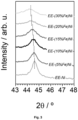
- Figure 2 shows diffractograms of the as prepared NiFe bimetallic anodes. They serve as fingerprint analysis of the different prepared electrocatalysts. They illustrate that the catalysts are mostly polycrystalline with small crystallite grain size (weak diffraction peaks are detected) as a consequence that the deposition process is at room temperature and that the iron atoms are incorporated within the nickel atomic network.
- the diffractograms in Figure 2 depict a characteristic intense diffraction peak at 54.6o attributed to the carbon paper used as substrate.
- two smaller diffraction peaks at approximately 44.5o and 51.9o are attributed to metallic nickel or a Ni containing alloy.
- the electrocatalysts electrodes prepared in examples 1 to 5 and comparative example 6 were evaluated for performance towards the OER in a three-electrode glass cell (i.e., half-cell configuration).
- This cell integrates a working anode (1.0 cm 2 geometric area), an Ag/AgCI reference electrode (KCI, 3M, Metrohm ® ) and a platinum foil (Metrohm ® ) counter electrode.
- the electrochemical characterization consists of cyclic voltammetry (CV) measurements. They were carried out with an Autolab PGSTAT30-ECOCHEMIE potentiostat/galvanostat. All measurements were performed at room temperature and 1.0 M KOH electrolyte aqueous solution. A nitrogen gas flow was bubbled for at least 20 minutes prior to test the electrodes and then it was kept bubbling during the experiments. The voltage range in the CV measurements was from 0.00 to +750 mV vs. Ag/AgCI. CV and the scan rate was 20 mV/s.
- Figure 4 shows cyclic voltammetry experiments carried out for electrodes fabricated in examples 1 to 5 and comparative example 6 in a three-electrode glass cell at room temperature, 1.0 M KOH electrolyte and 20 mV/s of scan rate.
- the incorporation of iron has a positive effect in the OER activity, leading to a significant increase in current density values (magnitude proportional to the O 2 formation at the anode) with respect to those obtained for Ni electrocatalyts fabricated in comparative example 6.
- the improvement in the electrocatalytic activity due to the incorporation of iron reflects in that the overpotential value required to reach 10 mA/cm 2 was the lowest (i.e., 307 mV) for the EE-(10%Fe)Ni anode.
- This enhancement is related to the substitution of Fe +3 for Ni +2 sites in Ni(OH) 2 and NiOOH, leading to new Ni-O local environments with a superior activity for the OER.
- Figure 4 shows that the addition of increasing amounts of Fe to the Ni catalyst favours the OER activity until a 10% in weight of Fe in the alloy becomes incorporated to the Nickel structure. Then, for iron incorporation percentages higher than 10% by weight, a plateau in the response towards OER is achieved.
- Example 2 The electrocatalyst electrode fabricated in Example 2 was analysed by scanning electron microscopy as prepared and after operation in half cell configuration
- Figure 5 shows SEM analysis of the used electrodes revealed a similar morphology and microstructure than that of the as prepared electrodes. This observation discards delamination of the catalyst from the backing support in the used electrodes and confirms the stability of bimetallic electrodes.
- Example 10 Experimental example about production of a complete electrolysis cell with a single MEA
- EE-(10%Fe)Ni electrode (catalyst load of 0.35 mg/cm 2 , equivalent thickness 540 nm) as described in Example 2 was used as anode and a EE-Ni electrode (load of 0.38 mg cm -2 , equivalent thickness 540 nm), as described in comparative example 1, was used as cathode.
- Catalyst films were deposited on carbon paper with a geometric area of 6.25 cm 2 .
- the electrodes were separated by an anion exchange membrane (Fumapem ® FAA-3-50 supplied by Fuel Cell Store).
- the geometric area of the electrodes in the MEA was 5 cm 2 and the catalyst load was determined by weighing before and after the MS-OAD deposition.
- the Fumapem ® FAA-3-50 anion exchange membrane was immersed in a 1.0 M KOH solution for 24 hours at room temperature to activate it, i.e., to replace Br - functional groups in the pristine membrane by OH - groups.
- Nickel bipolar plates with flow channels were used as current collectors and distributors of reactants and products.
- Anode and cathode reservoirs were fed with KOH water electrolyte solutions with 2 ml/min flow rate.
- a peristaltic pump (Pump drive 5001, Heidolph) was used to impulse the electrolyte solutions from two independent 1.0 litre buffer compartments to the electrode reservoirs recirculating the streams.
- Teflon gaskets were used to prevent gas leakage and to avoid short-circuiting.
- the bolt torque applied to seal the cell was chosen to optimize the electrochemical performance of the cell.
- the electrocatalyst prepared in example 2 was evaluated for electrochemical properties towards hydrogen production in a complete electrolysis cell formed by a single MEA as described in experimental Example 10.
- Figure 6 shows the linear sweep voltammetry characteristic of the said cell at 40 and 60 oC operation temperature.
- the electrocatalyst prepared in example 2 was evaluated for electrochemical properties towards hydrogen production in a membrane electrode assembly with identical conditions that in experimental example 10 except that an ionomer was added on top of the electrocatalyst prior to the MEA assembly.
- Figure 7 shows the current density vs polarization voltage characteristic of the said cell. A significant decrease of performance was attributed to the addition of ionomer to the cell
- Example 13 Experimental example about stability of an electrocatalyst incorporated into MEA
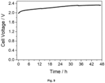
- the constant-current chronopotentiometric experiments consist of measuring the voltage output of the cell setting the density current at 400 mA/cm 2 a 40oC for 2 days.
- Figure 9 shows that only weak increase of voltage occurs over time (about 5 mV/hour), thus certifying the stability of the cell.
Landscapes
- Chemical & Material Sciences (AREA)
- Engineering & Computer Science (AREA)
- Chemical Kinetics & Catalysis (AREA)
- Materials Engineering (AREA)
- Metallurgy (AREA)
- Organic Chemistry (AREA)
- Electrochemistry (AREA)
- Mechanical Engineering (AREA)
- Inorganic Chemistry (AREA)
- Electrodes For Compound Or Non-Metal Manufacture (AREA)
- Electrolytic Production Of Non-Metals, Compounds, Apparatuses Therefor (AREA)
- Catalysts (AREA)
Abstract
Description
- The invention relates to a new kind of electrocatalyst to be incorporated as part of the electrodes, in the anode, in water electrolysers aimed for hydrogen production through the electrochemical splitting of water into oxygen and hydrogen. The electrocatalyst is characterized by a layered and porous structure that provides a high performance towards the oxygen evolution reaction in the absence of added ionomer. The object of the invention is framed in the field of energy.
- Hydrogen is a promising energy vector for a clean and sustainable energy usage for operation in domestic, transport and industrial sectors. Currently, most hydrogen production relies on the steam-methane (or other hydrocarbons) reforming. This procedure is responsible for emitting CO2 to the atmosphere in un-manageable amounts. For this reason, alternative hydrogen production processes using environmentally friendly routes (e.g., electricity from renewable sources) with no waste emissions constitute an urgent necessity. In this context, water electrolysis using intermittent renewable energy sources is emerging as a viable alternative, even at industrial scale, to those traditional methods for hydrogen production.
- Anion Exchange Membrane Water Electrolysis (AEMWE) is an emerging technology for hydrogen production. It operates at low temperatures (typically up to 80ºC) and has several advantages with respect to other more traditional electrolyser types as the reduction of membranes and electrocatalysts cost (e.g., in comparison with Proton Exchange Membrane Water Electrolysis typically requiring Pt group metals electrocatalysts) or the decrease of the problems associated to the formation of potassium carbonate in conventional alkaline electrolysis processes [J.E. Park, S.Y. Kang, S.-H. Oh, J.K. Kim, M.S. Lim, C.-Y. Ahn, Y.-H. Cho, Y.-E. Sung, High-performance anion-exchange membrane water electrolysis, Electrochim. Acta. 295 (2019) 99-106].
- Nickel and nickel-transition metal alloy based electrocatalyst electrodes have demonstrated a high activity in basic medium both for the oxygen evolution reaction (OER) and for hydrogen evolution reaction (HER), the former being the most restrictive reaction due to its higher overpotential. In this regard, catalyst based on Ni alloy formulations (e.g., Fe/Ni, Mo/Ni, but not restricted to these compositions) are known to decrease the OER overpotential, resulting in a highly active and low cost electrocatalyst compared with platinum metal group catalysts. However, improving the electrode performance to make AEMWE a competitive technology entails the optimization of micro-structure, porosity, amount, chemistry/composition and electrochemical surface area of the active phase of the electrocatalyst [A. Lim, H. Kim, D. Henkensmeier, S. Jong Yoo, J. Young Kim, S. Young Lee, Y.-E. Sung, J.H. Jang, H.S. Park, A study on electrode fabrication and operation variables affecting the performance of anion exchange membrane water electrolysis, J. Ind. Eng. Chem. 76 (2019) 410-418].
- Among other requirements, electrode electrocatalysts must present high electrochemical activity and stability, be cheap and have a secure supply. From an operational point of view, it is also critical to achieve a precise control over catalyst microstructure, composition, element distribution and chemical state. For practical exploitation, to reduce the cost related to the electrocatalyst load, electrocatalysts must possess a high specific activity towards the OER and HER reactions taking place in the electrolyser. These characteristics and requirements can be optimized by the usage of appropriate preparation methods.
- The most common routes to fabricate the electrodes for water electrolysis involve the incorporation of a catalyst slurry or ink into a gas diffusion layer (GDL) support. Typically, an ionomer compound is also added to the slurry or ink in order to promote the diffusion of hydroxyl groups to the anode active sites where the oxidation reaction leading to the formation of oxygen will take place. The catalysts themselves are mostly prepared as powders following wet routes as co-precipitation, hydrothermal, sol-gel, or directly incorporated into the electrode using electrodeposition methods. In these classical approaches, typical steps involve the preparation of precursor solutions, precipitation processes, washings, filtrations, dryings, calcinations, and/or milling. A clear disadvantage of these wet routes is that they involve solvents that produce unwanted wastes and imply a high number of steps, which handicap reproducibility when scaling up the manufacture procedure of the electrocatalyst.
- Due to the special characteristics and constrains of the electrolyser cells, not only a good choice of material catalysts is a critical requirement, but also achieving an optimised integration of the electrocatalyst within the electrode, in the so called membrane electrode assembly (MEA) and the complete stacked cell. This makes important not only finding the best electrocatalyst composition for the anode and cathode OER and HER reactions, or the use of the most appropriate ionomer type and load, but also the best way to integrate the appropriate electrocatalyst materials in the GDL and, ultimately, the cell. Selecting the most appropriate procedure for the synthesis and integration of the electrocatalyst is therefore a critical requirement to optimize the electrocatalyst performance and hence, the cell operating capacity.
- Traditional preparation methods of AEMWE catalyst electrodes using slurries or inks often involve the addition of polymeric organic ionomer molecules to increase the cell performance. The ionomer function is twofold. It serves as binder to the GDL supports and it increases the number of ion transport pathways between the electrocatalyst load and the anion exchange membrane, favouring the anion diffusion capacity up to the reaction sites. This compound influences the gas permeability and, thanks to its charged functional groups, facilitates the exchange of water and OH- ion at the catalyst surface. However, ionomers can be also disadvantageous if, through electrostatic/covalent interactions, their charged groups occupy catalyst active sites, thus increasing the HER and OER operating overpotentials. Over time, ionomers may undergo chemical degradation, resulting in a deterioration of the effective catalyst-ionomer interface and, therefore, the electrochemical active surface area of the electrode available for reaction. The development of new catalyst formulations avoiding the use of said ionomers is therefore a clear need to ensure the long term operation of electrolyser cells.
- The present invention proposes the incorporation of layered metal alloys electrocatalyst into gas diffusion layer backings by means of magnetron sputtering in oblique angle deposition geometry (MS-OAD) in order to obtain an ionomer-free electrode. The resulting porous and nanostructured electrodes can be integrated in membrane electrode assemblies and, afterwards, in suitable stacks to build AEMWE electrolysers.
- A first aspect of the present invention relates to a layered electrocatalyst electrode comprising
- a macroporous gas diffusion layer and current collector material substrate in the thickness range 0.05 mm to 1.0 mm; and
- an electrocatalyst with an equivalent thickness between 0.05 µm and 5 µm, wherein said electrocatalyst layer comprising a first and a second surface, wherein the first surface is in contact with the surface of the substrate, and wherein the second surface is opposite to the first surface in the direction defined by the thickness of the electrocatalytic layer;
- the substrate is selected from carbon paper, stainless-steel or nickel, wherein the carbon paper, stainless-steel and nickel are in the form of microfibers, sponge or mesh like structure;
- wherein the electrocatalyst layer comprises a NiFe alloy with an average value between 0.5% and 30% in weight of Fe in the alloy, wherein the NiFe alloy composition of the first surface of the electrocatalyst layer is between 0.5% and 2% in weight of Fe in the alloy, and the NiFe alloy composition of the electrocatalyst layer at the second surface is between 12% and 30% in weight of Fe in the alloy;
- wherein the electrocatalyst layer has a specific electrochemical active surface area (ECSA) between 1 and 100 cm2/mg with respect to the oxygen evolution reaction (OER) expressed in area per catalyst load units determined from the Nyquist plots of the electrode systems by means of electrical impedance spectroscopy measurement;
- wherein the electrocatalyst layer is a mesoporous layer with a porosity between 20% and 50% as measured by Kr gas adsorption isotherm and with a pore size varying between 2 and 100 nm determined by direct quantification of Scanning Electron Microscopy pictures of the films.
- The term "equivalent thickness" as used herein refers to the thickness of the NiFe alloy deposited on a flat substrate in the same deposition batch that the electrocatalysts on the GDL.
- The term "electrocatalyst layer" as used herein refers to an alloy layer with a controlled composition, porosity and microstructure that is deposited onto the macroporous substrate by magnetron sputtering in an oblique angle geometry. It is the electroactive catalyst layer inducing the OER or HER reaction upon application of a polarization potential. In the present invention the pore sizes are determined by direct quantification by Scanning Electron Microscopy pictures of the films and the pore volume measured by Kr gas adsorption isotherm. This electrocatalytic layer is arranged to be in contact with an electrolyte under operating conditions through the second surface described above.
- The term "macroporous" as used herein refers to an open pore structure with pore sizes in the range of 5-100 microns as determined by direct observation by means of scanning electron microscopy. The voids are defined by the arrangement of yarns or microfibers or by a sponge-like or mesh or similar structures and where the said voids have a size in the range of 5 to 100 microns.
- The term "macroporous gas diffusion layer and current collector" (GDL) as used herein refers to a macroporous material that act as support of the electrocatalyst layer. It refers to the said woven-, microfiber-, mesh- or sponge- like structure of the substrates in the form of a laminate that can be made of either carbon, nickel, stainless steel or any other material stable in the basic medium where the OER takes place.
- The term "electrochemical active surface area" (ECSA) as used herein refers to the equivalent specific area of the electrode material that is accessible to the electrolyte and that is used for the OER at the anode. It is measured in area per catalyst load units and it is determined according to the electrochemical double-layer capacitance method from the Nyquist plots of the electrode systems by means of electrical impedance spectroscopy measurements. It is related with the actual surface area of the mesoporous structure of the electrocatalyst layer and defines the effectiveness of a given layer to promote a specific reaction. The ECSA also can be determined from any other methods based on current voltage measurements at several voltage scan rates, the so called capacitance method. In the context of the present invention, it refers to the OER.
- The electrocatalyst layer as used in the present invention is deposited on rough or macroporous randomly oriented surfaces as those of the typical GDLs formed by the agglomeration of microfibers or with a sponge like microstructure, but keeps the average mesoporosity, conferring a potentially high electrochemical performance to the electrocatalyst materials prepared in these conditions. The high porosity and high specific ECSA of the electrocatalyst layer attainable by properly controlling the deposition process are other essential conditions for an optimized performance towards OER and HER. The GDL macroporous materials selected must present a high electron conductivity, enable the out-diffusion of the gases (H2 or O2) from the interface between the anion exchange membrane of the AEMWE cells and the electrocatalyst layer and be highly stable in the basic operation conditions of the electrochemical cell.
- A tailored in-depth distribution of porosity and composition along the electrocatalyst layer attainable by properly controlling the deposition process are additional key features of these electrocatalyst layers.
- Another advantage of the electrodes manufactured by the incorporation of the said electrocatalyst layer onto the GDL substrates as claimed in the present invention is the absence of any appreciable degradation or delamination of the electrocatalyst layer from the GDL after use, clearly evidencing the great stability of the electrodes. Furthermore, this stability can be confirmed because no traces of Fe and/or Ni have been observed after performing an inductively coupled plasma analysis of the alkaline water solutions feeding the electrolyser after experiments.
- When applying traditional electrode preparation methods, an ionomer is added to the catalyst ink or slurry as binder and to favour the ion transfer transport up to the reaction sites. Considering that the operation of the electrocatalyst layer of the present invention is not restricted by ion transfer mechanisms and that no delamination of the active catalyst layer has been detected after long-term operation, it appears that MS-OAD electrocatalysts do not require any binding agent to fix the catalyst layer to the GDL support. Thus, the electrocatalyst layer of the electrode of the present invention operates under an ionomer-free basis.
- Another advantage of the electrocatalyst in the form of a deposited layer covering the void surfaces of the most external regions of the GDL substrate resides in the little amount of active metal phase required for operation. Electrodes prepared as described in the present invention present similar electrochemical performance than conventional electrodes prepared by wet chemical routes with, at least, one order of magnitude less active material (e.g., Ni, NiFe, etc.) than in these other cases.
- Another advantage of the proposed alloy electrodes is the control of the elemental distribution in-depth within the layer structure according to different profiles, including a homogeneous distribution, a bilayer or multilayer distribution or a smoothly variable elemental profile distribution, among others. This allows tailoring the properties of the electrocatalyst layer, for example to bring in contact with the GDL support a composition more prompt to adherence and at the external zones in contact with the electrolyte a phase composition particularly active towards the OER or HER reaction. This control has also clear advantages regarding the cost of the metals since only a few atomic layers of the most expensive elements can be deposited in the outer zones to act as effective electrocatalyst in contact with the electrolyte when said electrode is in use.
- Thus, in a preferred embodiment of the present invention the GDL macroporous substrate acting as backing gas diffusion layer and current collector is nickel with the form of mesh like structure, because its highest robustness against chemical degradation in basic media.
- In other preferred embodiment, the stoichiometry of the alloy in the electrocatalyst layer has a homogeneous composition from first surface to the second surface; or wherein the stoichiometry of the alloy in the electrocatalyst layer has a linear compositional gradient of the percent in weight of Fe in the alloy in the direction of the layer thickness from the first surface at the interface with the GDL substrate to the second surface at the outmost external zones in contact with the electrolyte.
- In other preferred embodiment, the stoichiometry of the NiFe alloy is adjusted to an average value between 8 % and 12% in weight of Fe in the alloy. This ratio ensures the homogeneous distribution of iron atoms within the nickel atomic lattice and provides the maximum current when operated to induce the OER.
- In other preferred embodiment, the NiFe alloy composition of the first surface of the electrocatalyst layer is between 0.1% and 2% in weight of Fe in the alloy, and at the second outer zone is between 10% and 20% in weight of Fe in the alloy.
- In other preferred embodiment, the porosity of the electrocatalyst layer has a constant porosity along the whole layer thickness with a value of between 20 and 50% of the total volume of the layer, or wherein the porosity in the electrocatalyst layer vary linearly from the first surface to the second surface. In a more preferred embodiment, the porosity of the first surface zone is between 20% and 30% and the porosity of the second surface zone is between 40% and 50%.
- A varying profile of the porosity is achieved varying the gas plasma pressure during the MS deposition and/or the angle of deposition during MS-OAD.
- In other preferred embodiment, the electrocatalyst at the second surface further comprises a layer of a Ni(Fe)OxHy compound. Said compound leads to an enhancement of surface reactivity. This, combined with the metallic character of the bulk of the catalyst film, a feature that diminishes the electrical resistance of the electrode, further contributes to enhance the performance of the OER electrochemical process.
- The term "Ni(Fe)OxHy compound" as used herein refers to a layer of a mixed oxide-hydroxide of Fe and Ni which is deemed the active phase for the OER. This layer can be directly deposited by MS-OAD on the external surface of the NiFe electrocatalyst catalyst, but most commonly is generated from the FeNi alloy by the electrochemical cycling of the electrodes in the basic medium.
- A second aspect of the present invention is the process to obtain the layered electrocatalyst electrode characterized in that it comprises the following steps
- a) placing a macroporous gas diffusion layer and current collector material substrate selected from carbon paper, stainless steel and nickel wherein the carbon paper, stainless-steel and nickel are in the form of microfibers, sponge or mesh like structure in a holder of a vacuum chamber of a magnetron sputtering deposition apparatus;
- b) placing nickel and iron as a target or targets, or a NiFe alloy target or targets in the magnetron sputtering head located in the deposition apparatus of the step (a), wherein the target has a shape selected from disc, circular, square, cylinder and rectangle, and wherein the distance between the target and the substrate is between 2 cm and 30 cm and wherein the normal to the substrate surface is located at an angle of at least 70° with respect to the normal to the target surface at the race track formed on its surface due to sputtering, as carried out in a MS-OAD configuration;
- c) making vacuum in the chamber of step (b) until a base pressure of 4.10-6 mbar or below is achieved, introducing Ar gas at a flow between 20 and 40 standards cubic centimetre per minute and process pressure of 5.103 mbar and igniting the magnetron plasma by applying a pulsed DC power of between 50 W and 3000 W and a frequency of between 80 and 200 kHz to the target while the holder is rotating at a rotational speed between 1 and 10 turns per minute, whereby a layer of the NiFe electrocatalyst electrode is deposited;
and optionally - d) depositing or generating on the layered electrocatalyst electrode obtained in step (d) a layer of Ni(Fe)OxHy compound by a technique selected from MS-OAD or by electrochemical cycling of the electrode.
- Magnetron sputtering deposition technology is a classical physical vapour deposition procedure widely utilized in the industry for the preparation of compact layers for a large variety of applications in optics, tribology, hard coatings, etc. This invention claims that it is also an optimum choice for the fabrication of porous and nanostructured electrocatalyst layers suitable for their integration into highly performant AEMWE cells. In particular, when this method is utilized in an oblique angle deposition configuration (MS-OAD) and certain operation conditions, it provides nanostructured and highly porous electrocatalyst layers which, gifted with a high electrochemical active surface area, result very appropriate for their incorporation onto GDL as electrodes in AEMWE. The method is highly reproducible, scalable to large deposition areas, does not produce residues and works at room temperature. A careful adjustment of the deposition geometry and the plasma gas pressure during MS-OAD renders mesoporous nanostructured materials with a strict control of the composition, load and microstructure. The resulting nanostructured layer deposited onto the GDL facilitates the flow of liquid reactants (basic aqueous solution) and the release of the produced gases (H2, O2) through the nanometric pathways existing in the catalyst deposits decorating the fibrous/macroporous GDL backing. Another advantage of the process of the present invention is to prepare in-depth composition variable electrocatalyst layers with a tailored composition and porosity distributions in depth.
- Thus, a preferred embodiment of the process of the present invention, the target has a disc shape with a diameter size of between 50 mm and 100 mm, and wherein the pulse DC power of step (c) is between 50 W and 300 W and a frequency of between 80 and 140 kHz.
- In other preferred embodiment the nickel/iron target or targets is a nickel with a shape selected from disc, circular, square, cylinder and rectangle, more preferably with circular shape with a diameter between 50 mm and 100 mm with iron strips with a width of between 1 mm and 2 mm and a thickness between 0.2 and 0.3 mm, axially wrapped on the disc surface.
- In other preferred embodiment of the process, the target is a NiFe alloy with between 2.0% and 20% in weight of Fe.
- To achieve the expected activity of the porous electrocatalyst, it is fabricated by magnetron sputtering at oblique angles. Due to the fact that MS-OAD induces intrinsically inhomogeneous deposits on large substrates, substrate movement during deposition is mandatory to achieve homogeneous loads on substrates. There are various possibilities to achieve a homogeneous deposition.
- In a first MS-OAD configuration option, the experimental set-up consists of a rotatable sample holder whose axis is placed normal to the main direction of particle flux from either the magnetron heads. The GDL backing electrode is attached to the sample holder and continuously rotated during the deposition of the mesoporous electrocatalyst. In these conditions the microfiber, sponge or mesh like structure of the textured substrate support becomes decorated with a mesoporosus NiFe electrocatalyst layer. On flat substrates, this geometrical configuration and realization procedure renders vertically oriented mesoporous nanocolumnar structures.
- In another preferred embodiment of the process, the deposition of the electrocatalyst is done in even number of steps at a fixed perpendicular orientation of the GDL substrate with respect to a sputtering target, and azimuthally turning the sample holder 180º for each deposition step. By this configuration the substrate surface normal forms an oblique angle with respect to a perpendicular line to the target. This second option produces a zig-zag microstructure when deposited on flat substrates. When using structured GDL supports, the result is a nanostructured layer covering the pores surfaces at the shallow regions of the supports and a homogeneous thickness distribution of the electrocatalyst layer on the whole substrate.
- In another configuration, generally using a rectangular sputtering target, a flexible GDL backing can be attached to a cylindrical sample holder that turns continuously around its shaft axis during deposition. This latter configuration is compatible with roll-to-roll procedures and permits the optimization of the deposition of material onto the substrate. In these conditions, the main flow of material from the sputtered target will reach the GDL substrate at averaged local oblique geometries, thus warrantying a high mesoporosity.
- Other possible realizations of the MS-OAD process can also be used to get the desired porous microstructure up to 50% of the volume of the layer as the use of slits and linear movable substrates or the twisting of substrates at giving moments of the deposition in order to homogenize the electrocatalyst layer thickness over the entire substrate. The use of slits serves to select depositing particles coming from the target within a certain solid angle and arriving to the substrate at an oblique angle with respect to its surface normal. An inconvenient of this configuration is that only a small fraction of the sputtered material coming from the target passes through the slit up to the substrate.
- A third aspect of the present invention is a membrane electrode assembly (MEA) characterized in that it comprises two electrodes, at least one of said electrode is the electrode described above in the present invention, and an anion exchange membrane.
- The term "membrane electrode assembly (MEA)" as used herein refers to the anion exchange membrane sandwiched between an anode and a cathode, with anode/cathode consisted of GLD with corresponding deposited electrocatalyst optimised for OER/HER, respectively. The whole ensemble is embodied and pressed between to bipolar metal plates enabling the access of the electrolyte, generally a KOH aqueous solution with a given concentration, typically 1.0 M, and the release of the produced gases (O2 at the anode, H2 at the cathode)
- In a preferred embodiment of the MEA,
- one of the electrodes is the electrode described above in the present invention, and it is suitable to act as an anode; and
- second electrode is a porous Ni layer acting as electrocatalysts and deposited following the same MS-OAD procedure from a pure Ni target onto another backing gas diffusion layer and current collector material that is suitable to act as a cathode;
- Depending on the size of the electrodes and the efficiency of the process, current densities up to 1500 mA cm-2 can be produced. The MEAs operating temperature is, generally between 60 and 80 °C
- A fourth aspect of the present invention is an Anion Exchange Membrane Water Electrolysis (AEMWE) electrolyser characterized in that it comprises a stacking of at least two MEA units connected electrically in series in a compact system. In a preferred embodiment, the Anion Exchange Membrane Water Electrolysis (AEMWE) electrolyser further comprises a stacking of more than five MEAs arranged in a compact system in a way such that the electrodes are electrically connected in series and the electrolyte circulates in parallel through the various anode and cathode compartments and the gases are released separately through outlet tubing.
- The term "AEMWE electrolysers" as used herein refers to the compact stacking system of several MEAs described before, with the appropriate shielding gaskets and plates and gas inlets and outlets, etc. and where the aqueous electrolyte is adjusted to basic conditions, generally to pH=10 or above
- A fifth aspect of the present invention is a method for hydrogen production characterized in that it comprises the following steps
- i. feeding the AEMWE electrolyser described above in the present invention with a KOH aqueous solution between 0.1 M and 4 M at a temperature of between 40 ºC and 85ºC;
- ii. applying a polarization voltage between 1.8 V and 2.2 V to each one of the MEA unit cells, electrically connected in series in the stack.
- In a preferred embodiment, the temperature in step i) is between 60 ºC and 80 ºC.
An advantage of the so built AEMWE electrolysers is their operation without adding an ionomer to the electrocatalysts, thus avoiding operational problems related with degradation or contamination of the electrodes and, therefore facilitating a long operational time. Another, a significant reduction in the amount of active phase in the electrocatalysts and the consequent reduction of associated costs. - The sixth aspect of the present invention is the use of the layered electrocatalyst electrode described above in the present invention as an anode in AEMWE electrolysers.
- Unless otherwise defined, all technical and scientific terms used herein have the same meaning as commonly understood by one of ordinary skilled in the art to which this invention belongs. Methods and materials similar or equivalent to those described herein can be used in the practice of the present invention. Throughout the description and claims the word "comprise" and its variations are not intended to exclude other technical features, additives, components, or steps. Additional objects, advantages and features of the invention will become apparent to those skilled in the art upon examination of the description or may be learned by practice of the invention. The following examples, drawings and sequence listing are provided by way of illustration and are not intended to be limiting of the present invention.
-
-
Fig. 1 . Scheme of the geometry of the MS-OAD process used for the fabrication of electrocatalysts in examples 1 to 5 and comparative example 6 -
Fig. 2 . Diffractograms of the as prepared NiFe bimetallic electrocatalysts used as anodes in examples 1 to 5 and comparative example 6 -
Fig. 3 . Expanded view of diffractograms around Ni(220) diffraction peak of the as prepared NiFe bimetallic electrocatalysts used as anodes in examples 1 to 5 and comparative example 6 -
Fig. 4 . Cyclic voltammetry experiments carried out for electrocatalysts fabricated in examples 1 to 5 and comparative example 6 in a three-electrode glass cell at room temperature, 1.0 M KOH electrolyte and 20 mV/s of scan rate. -
Fig. 5 . SEM images in normal view of EE-10%Fe-Ni (EE, electrocatalyst electrode) electrocatalyst as-prepared and after its usage in the three-electrode glass cell. -
Fig. 6 . Temperature. Linear sweep voltammetry characteristic of the electrocatalyst prepared in example 2 and integrated in a single MEA electrolysis cell according to experimental example 4 at 40 and 60ºC operation temperatures. -
Fig. 7 . lonomer. Linear sweep voltammetry characteristic of the electrocatalyst prepared in example 2 and integrated in a single MEA electrolysis cell with and without ionomer at 40ºC operation temperature. -
Fig. 8 . Stability. 1st and 200th cycle linear sweep voltammetry characteristic of the electrocatalyst prepared in example 2 and integrated in a single MEA electrolysis cell according to experimental example 4 at 40ºC operation temperature. -
Fig. 9 . Stability. Constant-current chronopotentiometric measurement acquired at 400 mA/cm2 and 40ºC for 2 days of the electrocatalyst prepared in example 2 and integrated in a single MEA electrolysis cell at 40ºC operation temperature. - A NiFe bimetallic electrocatalyst electrode of the present invention was prepared at room temperature (25 ºC) by MS-OAD with a geometrical arrangement as described in
Figure 1 . A circular nickel sputtering target (GoodFellow Cambridge Ltd., 99.9 at. %, 50 mm diameter) with one axially wrapped iron strip (GoodFellow Cambridge Ltd., 99.5 at. %, 1.5 mm width, 0.25 mm thickness) was used as source of the bimetallic alloy. The sputtering target was operated using a pulsed DC power supply (AE Pinnacle+) at 150 W and a frequency of 120 kHz. Carbon paper GDL baking electrodes (TGP-H-90, Fuel cell Earth) were used as substrates. - Similar electrocatalyst layers can be prepared substituting the Ni target with Fe strips by a FeNi alloy target with the desired composition.
- The carbon paper substrate was placed on a circular rotatable sample holder of 10 cm diameter. This holder was positioned in an angle of ∼78º with respect the surface of the sputtering target and was continuously rotating at 5 turns per minute to homogenise the thickness and microstructure of deposited films. This configuration is also compatible with the deposition from two targets located in similar radial positions with respect to the rotating disc. Argon was used as plasma gas. A flow of 30 sccm (standard cubic centimetres per minute) was dosed in the preparation chamber yielding a process pressure of 5.10-3 mbar. The base pressure in the system was 2.10-6 mbar. Time of deposition of 100 minutes was required to achieve the desired amount of electrocatalyst. The deposition rate was about 5 nm equivalent thickness of deposited material per minute.
- Carbon paper (TGP-H-90, Fuel Cell Earth) was used as support of the electrocatalysts. In addition, polished silicon wafers were also used as substrates for cross-section microscopy analysis of the different nickel based thin films. We define equivalent thickness as the physical thickness determined by cross-section SEM analysis for the thin films deposited simultaneously on a flat silicon wafer substrate. In these conditions, the iron content in the nanostructured bimetallic NiFe alloy deposit was about 5 % by weight.
- An electrocatalyst electrode for AEMWE electrolyser was fabricated in the same manner as in example 1, except that the number of iron strips wrapped to the Ni sputtering target were two evenly distributed. In these conditions the iron content in the nanostructured bimetallic NiFe alloy deposit was about 10% by weight.
- Similar electrocatalyst layers can be prepared substituting the Ni target with Fe strips by a FeNi alloy target with the desired composition.
- An electrocatalyst electrode for AEMWE electrolyser was fabricated in the same manner as in example 1, except that the number of iron strips wrapped to the Ni sputtering target were three evenly distributed. In these conditions, the iron content in the nanostructured bimetallic NiFe alloy deposit was about 15% by weight.
- Similar electrocatalyst layers can be prepared substituting the Ni target with Fe strips by a FeNi alloy target with the desired composition.
- An electrocatalyst electrode for AEMWE electrolyser was fabricated in the same manner as in example 1, except that the number of iron strips wrapped to the Ni sputtering target were four evenly distributed. In these conditions, the iron content in the nanostructured bimetallic NiFe alloy deposit was about 20% by weight.
- Similar electrocatalyst layers can be prepared substituting the Ni target with Fe strips by a FeNi alloy target with the desired composition.
- An electrocatalyst electrode for AEMWE electrolyser was fabricated in the same manner as in example 1, except that the number of iron strips wrapped to the Ni sputtering target were six evenly distributed. In these conditions, the iron content in the nanostructured bimetallic NiFe alloy was about 30% by weight.
- Similar electrocatalyst layers can be prepared substituting the Ni target with Fe strips by a FeNi alloy target with the desired composition.
- A reference nanostructured electrocatalyst electrode for AEMWE electrolyser was fabricated in the same manner as in example 1, except that there were no iron strips wrapped to the Ni sputtering target.
- The electrocatalyst electrodes fabricated in Examples 1 to 5 and comparative example 6 were analysed by X-ray diffraction (XRD).
Figure 2 shows diffractograms of the as prepared NiFe bimetallic anodes. They serve as fingerprint analysis of the different prepared electrocatalysts. They illustrate that the catalysts are mostly polycrystalline with small crystallite grain size (weak diffraction peaks are detected) as a consequence that the deposition process is at room temperature and that the iron atoms are incorporated within the nickel atomic network. - The diffractograms in
Figure 2 depict a characteristic intense diffraction peak at 54.6º attributed to the carbon paper used as substrate. In addition, two smaller diffraction peaks at approximately 44.5º and 51.9º, are attributed to metallic nickel or a Ni containing alloy. - An enlarged view of the peaks at 44.5º, due to the Ni(220) reflections in a metallic based Ni network, is shown in
Figure 3 . It is apparent that their intensities decrease, their widths increase and their positions shift as the iron content in the samples increases. These effects are due to the random incorporation of iron atoms within the face centred cubic (fcc) structure of Ni, forming a kind of alloy. The lack of diffracted reflexions attributable to metallic Fe confirms the incorporation of Fe into the Ni structure. Overall, this XRD analysis shows that bimetallic electrodes consist of a metallic alloy with small crystallite grain size. - The electrocatalysts electrodes prepared in examples 1 to 5 and comparative example 6 were evaluated for performance towards the OER in a three-electrode glass cell (i.e., half-cell configuration).
- This cell integrates a working anode (1.0 cm2 geometric area), an Ag/AgCI reference electrode (KCI, 3M, Metrohm®) and a platinum foil (Metrohm®) counter electrode.
- The electrochemical characterization consists of cyclic voltammetry (CV) measurements. They were carried out with an Autolab PGSTAT30-ECOCHEMIE potentiostat/galvanostat. All measurements were performed at room temperature and 1.0 M KOH electrolyte aqueous solution. A nitrogen gas flow was bubbled for at least 20 minutes prior to test the electrodes and then it was kept bubbling during the experiments. The voltage range in the CV measurements was from 0.00 to +750 mV vs. Ag/AgCI. CV and the scan rate was 20 mV/s.
-
Figure 4 shows cyclic voltammetry experiments carried out for electrodes fabricated in examples 1 to 5 and comparative example 6 in a three-electrode glass cell at room temperature, 1.0 M KOH electrolyte and 20 mV/s of scan rate. - As shown in
Figure 4 , the incorporation of iron has a positive effect in the OER activity, leading to a significant increase in current density values (magnitude proportional to the O2 formation at the anode) with respect to those obtained for Ni electrocatalyts fabricated in comparative example 6. The improvement in the electrocatalytic activity due to the incorporation of iron reflects in that the overpotential value required to reach 10 mA/cm2 was the lowest (i.e., 307 mV) for the EE-(10%Fe)Ni anode. - This enhancement is related to the substitution of Fe+3 for Ni+2 sites in Ni(OH)2 and NiOOH, leading to new Ni-O local environments with a superior activity for the OER.
Figure 4 shows that the addition of increasing amounts of Fe to the Ni catalyst favours the OER activity until a 10% in weight of Fe in the alloy becomes incorporated to the Nickel structure. Then, for iron incorporation percentages higher than 10% by weight, a plateau in the response towards OER is achieved. - The electrocatalyst electrode fabricated in Example 2 was analysed by scanning electron microscopy as prepared and after operation in half cell configuration
Figure 5 shows SEM analysis of the used electrodes revealed a similar morphology and microstructure than that of the as prepared electrodes. This observation discards delamination of the catalyst from the backing support in the used electrodes and confirms the stability of bimetallic electrodes. - EE-(10%Fe)Ni electrode (catalyst load of 0.35 mg/cm2, equivalent thickness 540 nm) as described in Example 2 was used as anode and a EE-Ni electrode (load of 0.38 mg cm-2, equivalent thickness 540 nm), as described in comparative example 1, was used as cathode.
- Catalyst films were deposited on carbon paper with a geometric area of 6.25 cm2.
- The electrodes were separated by an anion exchange membrane (Fumapem® FAA-3-50 supplied by Fuel Cell Store). The geometric area of the electrodes in the MEA was 5 cm2 and the catalyst load was determined by weighing before and after the MS-OAD deposition.
- Prior to use, the Fumapem® FAA-3-50 anion exchange membrane was immersed in a 1.0 M KOH solution for 24 hours at room temperature to activate it, i.e., to replace Br- functional groups in the pristine membrane by OH- groups.
- Nickel bipolar plates with flow channels were used as current collectors and distributors of reactants and products. Anode and cathode reservoirs were fed with KOH water electrolyte solutions with 2 ml/min flow rate. A peristaltic pump (Pump drive 5001, Heidolph) was used to impulse the electrolyte solutions from two independent 1.0 litre buffer compartments to the electrode reservoirs recirculating the streams. Teflon gaskets were used to prevent gas leakage and to avoid short-circuiting. The bolt torque applied to seal the cell was chosen to optimize the electrochemical performance of the cell.
- The electrocatalyst prepared in example 2 was evaluated for electrochemical properties towards hydrogen production in a complete electrolysis cell formed by a single MEA as described in experimental Example 10.
- The electrochemical measurements of the complete AEMWE cell were carried out with the Autolab potentiostat/galvanostat. Experiments consisted of linear sweep voltammetries (LSV) varying the potential from 1.0 to 2.2 V with a scan rate of 5 mV/s. at 40 and 60 ºC process temperatures.
-
Figure 6 shows the linear sweep voltammetry characteristic of the said cell at 40 and 60 ºC operation temperature. - The electrocatalyst prepared in example 2 was evaluated for electrochemical properties towards hydrogen production in a membrane electrode assembly with identical conditions that in experimental example 10 except that an ionomer was added on top of the electrocatalyst prior to the MEA assembly.
-
Figure 7 shows the current density vs polarization voltage characteristic of the said cell. A significant decrease of performance was attributed to the addition of ionomer to the cell - The electrocatalyst prepared in example 2 and incorporated in a MEA as described in experimental example 10 was evaluated for stability in operation conditions. Aging experiments consisted of cyclic voltammetry measurements (200 I-V cycles, performed with scan rate of 50 mV/s at 40 ºC).
Figure 8 shows that not significant variation of initial characteristic is observed, thus certifying the stability of the cell. - The constant-current chronopotentiometric experiments consist of measuring the voltage output of the cell setting the density current at 400 mA/cm2 a 40ºC for 2 days.
Figure 9 shows that only weak increase of voltage occurs over time (about 5 mV/hour), thus certifying the stability of the cell.
Claims (15)
- A layered electrocatalyst electrode comprising• a macroporous gas diffusion layer and current collector material substrate in the thickness range 0.05 to 1.0 mm; and• an electrocatalyst with an equivalent thickness between 0.05 µm and 5 µm, wherein said electrocatalyst layer comprising a first and a second surface, wherein the first surface is in contact with the surface of the substrate, and wherein the second surface is opposite to the first surface in the direction defined by the thickness of the electrocatalytic layer;characterized in thatthe substrate is selected from carbon paper, stainless-steel or nickel, wherein carbon paper, stainless-steel and nickel are in the form of microfibers, sponge or mesh like structure;wherein the electrocatalyst layer comprises a NiFe alloy with an average value between 0.5% and 30% in weight of Fe in the alloy, wherein the NiFe alloy composition of the first surface of the electrocatalyst layer is between 0.5% and 2% in weight of Fe in the alloy, and the NiFe alloy composition of the electrocatalyst layer at the second surface is between 12% and 30% in weight of Fe in the alloy;wherein the electrocatalyst layer has a specific electrochemical active surface area between 1 and 100 cm2/mg with respect to the oxygen evolution reaction expressed in area per catalyst load units determined from the Nyquist plots of the electrode systems by means of electrical impedance spectroscopy measurement;wherein the electrocatalyst layer is a mesoporous layer with a total porosity between 20% and 50% measured by Kr gas adsorption isotherm and with a pore size varying between 2 and 100 nm determined by direct quantification on Scanning Electron Microscopy pictures of the films.
- Layered electrocatalyst electrode according to claim 1, wherein macroporous substrate as backing gas diffusion layer and current collector is nickel with the form of mesh like structure.
- Layered electrocatalyst electrode according to any claims 1 or 2, wherein the stoichiometry of the alloy in the electrocatalyst layer has a homogeneous composition from first surface to the second surface; or wherein the stoichiometry of the alloy in the electrocatalyst layer has a linear compositional gradient of the percent in weight of Fe in the alloy in the direction of the layer thickness from the first surface in contact with the GDL substrate to the second surface outmost external zones.
- Layered electrocatalyst electrode according to any claims 1 to 3, wherein NiFe alloy has an average value between 8 % and 12 % in weight of Fe in the alloy.
- Layered electrocatalyst electrode according to any claims 1 to 4, wherein the NiFe alloy composition of the first surface of the electrocatalyst layer is between 0.1% and 2%. in weight of Fe in the alloy, and at the second outer zone is between 10% and 20% in weight of Fe in the alloy.
- Layered electrocatalyst electrode according to any claims 1 to 5, wherein the porosity of the electrocatalyst layer has a constant porosity along the whole layer thickness with a value of between 20 and 50% of the total volume of the layer; or wherein the porosity in the electrocatalyst layer vary linearly from the first surface to the second surface.
- Layered electrocatalyst electrode according to any claims 1 to 6, wherein the electrocatalyst second surface further comprises a layer of a Ni(Fe)OxHy compound.
- A process to obtain the layered electrocatalyst electrode according to any of claims 1 to 7 characterized in that it comprises the following stepsa) placing a macroporous gas diffusion layer and current collector material substrate selected from carbon paper, stainless steel of nickel, wherein the carbon paper, stainless-steel and nickel are in the form of microfibers, sponge or mesh like structure as substrate in a holder of a vacuum chamber of a magnetron sputtering deposition apparatus;b) placing nickel and iron as a target or targets, or a NiFe alloy target in the magnetron sputtering head located in the deposition apparatus of the step (a), wherein the target has a shape selected from disc, circular, square, cylinder and rectangle, and wherein the distance between the target and the substrate is between 2 cm and 30 cm and wherein the normal to the substrate surface is located at an angle of at least 70° with respect to the normal to the target surface at the race track formed on its surface due to sputtering in a MS-OAD configuration;c) making vacuum in the chamber of step (b) until a base pressure of 4.10-6 mbar or below is achieved, introducing Ar gas at a flow between 20 and 40 standards cubic centimetre per minute and process pressure of 5.10-3 mbar and igniting the magnetron plasma by applying a pulsed DC power of between 50 W and 3000 W and a frequency of between 80 and 200 kHz to the target while the holder is rotating at a rotational speed between 1 and 10 turns per minute, whereby a layer of the NiFe electrocatalyst electrode is deposited;
and optionallyd) depositing or generating on the layered electrocatalyst electrode obtained in step (d) a layer of Ni(Fe)OxHy compound by a technique selected from MS-OAD or by electrochemical cycling of the electrode. - Process according to claim 8, wherein the nickel/iron target or targets is a nickel with a shape selected from disc, square, cylinder and rectangle, more preferably with circular shape with a diameter between 50 and 100 mm with iron strips with a width of between 1 mm and 2 mm and a thickness of between 0.2 and 0.3 mm, axially wrapped on the disc surface.
- A metal electrode assembly characterized in that it comprises two electrodes, at least one of said electrode is the layered electrocatalyst electrode described in anyone of claims 1 to 7.
- A metal electrode assembly according to claim 10, wherein• one of the electrodes is the layered electrocatalyst electrode, and it is suitable to act as an anode; and• second electrode is a porous Ni layer acting as electrocatalysts and deposited following the same MS-OAD procedure onto another backing gas diffusion layer and current collector material that is suitable to act as a cathode;wherein the assembly between anode and cathode is made by an anion exchange membrane and electrodes are connected to an external electrical circuit applying the desired difference of voltage between anode and cathode, generally from 1.5 to 2.5 V.
- An AEMWE electrolyser characterized in that it comprises a stacking of at least two MEA units according to any claims 10 or 11 connected electrically in series in a compact system.
- An AEMWE electrolyser according to claim 12, wherein further comprises a stacking of more than five MEA arranged in a compact system in a way such that the electrodes are electrically connected in series and the electrolyte, circulates in parallel through the various anode and cathode compartments and the gases released separately through inlet and outlet tubing.
- A method for hydrogen production characterized in that it comprises the following stepsi. feeding the Anion Exchange Membrane Water Electrolysis electrolyser described in anyone claims 10 or 11 with a KOH solution between 0.1 M and 4 M at a temperature of between 40 ºC and 85ºC, preferably the temperature in step i) is between 60 and 80º;ii. applying a polarization voltage of between 1.8 V and 2.2 V to each one of the metal electrode unit cells, electrically connected in series in the stack.
- Use of the layered electrocatalyst electrode according to any claims 1 to 7 as an anode in water electrolysers.
Priority Applications (12)
| Application Number | Priority Date | Filing Date | Title |
|---|---|---|---|
| EP21383006.0A EP4177379B1 (en) | 2021-11-05 | 2021-11-05 | Porous ionomer free layered metal alloy electrocatalyst electrode |
| MA67140A MA67140B1 (en) | 2021-11-05 | 2021-11-05 | ELECTROCATALYST ELECTRODE MADE OF POROUS IONOMER-FREE LAYER METAL ALLOY |
| ES21383006T ES2983480T3 (en) | 2021-11-05 | 2021-11-05 | Layered metal alloy electrocatalyst electrode without porous ionomer |
| MX2024004556A MX2024004556A (en) | 2021-11-05 | 2022-10-21 | Porous ionomer free layered metal alloy electrocatalyst electrode. |
| KR1020247009029A KR20240057414A (en) | 2021-11-05 | 2022-10-21 | Porous ionomer-free layered metal alloy electrocatalytic electrode |
| AU2022361708A AU2022361708A1 (en) | 2021-11-05 | 2022-10-21 | Porous ionomer free layered metal alloy electrocatalyst electrode |
| CA3234096A CA3234096A1 (en) | 2021-11-05 | 2022-10-21 | Porous ionomer free layered metal alloy electrocatalyst electrode |
| PE2024000364A PE20241037A1 (en) | 2021-11-05 | 2022-10-21 | LAYERED METAL ALLOY ELECTROCATALYST ELECTRODE FREE OF POROUS IONOMER |
| JP2024527123A JP2024546367A (en) | 2021-11-05 | 2022-10-21 | Porous ionomer-free layered metal alloy electrocatalytic electrodes |
| PCT/EP2022/079454 WO2023057656A1 (en) | 2021-11-05 | 2022-10-21 | Porous ionomer free layered metal alloy electrocatalyst electrode |
| CL2024000726A CL2024000726A1 (en) | 2021-11-05 | 2024-03-12 | Porous ionomer-free layered metal alloy electrocatalyst electrode |
| CONC2024/0004641A CO2024004641A2 (en) | 2021-11-05 | 2024-04-12 | Porous Ionomer Free Layered Metal Alloy Electrocatalyst Electrode |
Applications Claiming Priority (1)
| Application Number | Priority Date | Filing Date | Title |
|---|---|---|---|
| EP21383006.0A EP4177379B1 (en) | 2021-11-05 | 2021-11-05 | Porous ionomer free layered metal alloy electrocatalyst electrode |
Publications (3)
| Publication Number | Publication Date |
|---|---|
| EP4177379A1 true EP4177379A1 (en) | 2023-05-10 |
| EP4177379B1 EP4177379B1 (en) | 2024-05-29 |
| EP4177379C0 EP4177379C0 (en) | 2024-05-29 |
Family
ID=78725413
Family Applications (1)
| Application Number | Title | Priority Date | Filing Date |
|---|---|---|---|
| EP21383006.0A Active EP4177379B1 (en) | 2021-11-05 | 2021-11-05 | Porous ionomer free layered metal alloy electrocatalyst electrode |
Country Status (12)
| Country | Link |
|---|---|
| EP (1) | EP4177379B1 (en) |
| JP (1) | JP2024546367A (en) |
| KR (1) | KR20240057414A (en) |
| AU (1) | AU2022361708A1 (en) |
| CA (1) | CA3234096A1 (en) |
| CL (1) | CL2024000726A1 (en) |
| CO (1) | CO2024004641A2 (en) |
| ES (1) | ES2983480T3 (en) |
| MA (1) | MA67140B1 (en) |
| MX (1) | MX2024004556A (en) |
| PE (1) | PE20241037A1 (en) |
| WO (1) | WO2023057656A1 (en) |
Cited By (1)
| Publication number | Priority date | Publication date | Assignee | Title |
|---|---|---|---|---|
| WO2025037300A1 (en) * | 2023-08-15 | 2025-02-20 | Hydrolite Ltd | Substrates, oxygen electrodes and electrochemical devices |
Families Citing this family (5)
| Publication number | Priority date | Publication date | Assignee | Title |
|---|---|---|---|---|
| KR102929925B1 (en) * | 2023-08-25 | 2026-02-24 | 포항공과대학교 산학협력단 | Surface morphology-controlled catalytic electrodes for gas generation, Method for fabricating the same and catalytic system for gas generation having the same |
| WO2025149794A1 (en) * | 2024-01-11 | 2025-07-17 | Sungreenh2 Pte. Ltd. | Electrolyser system and method of use |
| JP2026056430A (en) * | 2024-09-19 | 2026-04-01 | 株式会社東芝 | Electrodes, membrane electrode assemblies, electrochemical cells, stacks, electrolytic devices |
| CN119372708B (en) * | 2024-12-30 | 2025-05-16 | 上海治臻新能源股份有限公司 | A hydrogen evolution electrode for cathode of AEM electrolytic cell and preparation method thereof |
| CN119372709B (en) * | 2024-12-30 | 2025-05-06 | 上海治臻新能源股份有限公司 | Method for preparing oxygen evolution electrode |
-
2021
- 2021-11-05 MA MA67140A patent/MA67140B1/en unknown
- 2021-11-05 ES ES21383006T patent/ES2983480T3/en active Active
- 2021-11-05 EP EP21383006.0A patent/EP4177379B1/en active Active
-
2022
- 2022-10-21 WO PCT/EP2022/079454 patent/WO2023057656A1/en not_active Ceased
- 2022-10-21 KR KR1020247009029A patent/KR20240057414A/en not_active Ceased
- 2022-10-21 JP JP2024527123A patent/JP2024546367A/en active Pending
- 2022-10-21 AU AU2022361708A patent/AU2022361708A1/en not_active Abandoned
- 2022-10-21 CA CA3234096A patent/CA3234096A1/en active Pending
- 2022-10-21 MX MX2024004556A patent/MX2024004556A/en unknown
- 2022-10-21 PE PE2024000364A patent/PE20241037A1/en unknown
-
2024
- 2024-03-12 CL CL2024000726A patent/CL2024000726A1/en unknown
- 2024-04-12 CO CONC2024/0004641A patent/CO2024004641A2/en unknown
Non-Patent Citations (6)
| Title |
|---|
| A. LIMH. KIMD. HENKENSMEIERS. JONG YOOJ. YOUNG KIMS. YOUNG LEEY.-E. SUNGJ.H. JANGH.S. PARK: "A study on electrode fabrication and operation variables affecting the performance of anion exchange membrane water electrolysis", J. IND. ENG. CHEM., vol. 76, 2019, pages 410 - 418, XP085697423, DOI: 10.1016/j.jiec.2019.04.007 |
| J.E. PARKS.Y. KANGS.-H. OHJ.K. KIMM.S. LIMC.-Y. AHNY.-H. CHOY.-E. SUNG: "High-performance anion-exchange membrane water electrolysis", ELECTROCHIM. ACTA., vol. 295, 2019, pages 99 - 106, XP085564655, DOI: 10.1016/j.electacta.2018.10.143 |
| LÓPEZ-FERNÁNDEZ E ET AL: "Ionomer-Free Nickel-Iron bimetallic electrodes for efficient anion exchange membrane water electrolysis", CHEMICAL ENGENEERING JOURNAL, ELSEVIER, AMSTERDAM, NL, vol. 433, 23 November 2021 (2021-11-23), XP086954123, ISSN: 1385-8947, [retrieved on 20211123], DOI: 10.1016/J.CEJ.2021.133774 * |
| LÓPEZ-FERNÁNDEZ E. ET AL: "Chemistry and Electrocatalytic Activity of Nanostructured Nickel Electrodes for Water Electrolysis", ACS CATALYSIS, vol. 10, no. 11, 5 June 2020 (2020-06-05), US, pages 6159 - 6170, XP055919726, ISSN: 2155-5435, DOI: 10.1021/acscatal.0c00856 * |
| LÓPEZ-FERNÁNDEZ ESTER ET AL: "Recent Advances in Alkaline Exchange Membrane Water Electrolysis and Electrode Manufacturing", MOLECULES, vol. 26, no. 21, 1 November 2021 (2021-11-01), DE, pages 6326, XP055919221, ISSN: 1433-1373, DOI: 10.3390/molecules26216326 * |
| ZHANG DOUDOU ET AL: "One-step preparation of optically transparent Ni-Fe oxide film electrocatalyst for oxygen evolution reaction", ELECTROCHIMICA ACTA, ELSEVIER, AMSTERDAM, NL, vol. 169, 18 April 2015 (2015-04-18), pages 402 - 408, XP029130863, ISSN: 0013-4686, DOI: 10.1016/J.ELECTACTA.2015.04.101 * |
Cited By (1)
| Publication number | Priority date | Publication date | Assignee | Title |
|---|---|---|---|---|
| WO2025037300A1 (en) * | 2023-08-15 | 2025-02-20 | Hydrolite Ltd | Substrates, oxygen electrodes and electrochemical devices |
Also Published As
| Publication number | Publication date |
|---|---|
| JP2024546367A (en) | 2024-12-20 |
| EP4177379B1 (en) | 2024-05-29 |
| EP4177379C0 (en) | 2024-05-29 |
| MA67140B1 (en) | 2024-09-30 |
| ES2983480T3 (en) | 2024-10-23 |
| CO2024004641A2 (en) | 2024-04-29 |
| AU2022361708A1 (en) | 2024-03-14 |
| ES2983480T8 (en) | 2024-12-11 |
| CA3234096A1 (en) | 2023-04-13 |
| MX2024004556A (en) | 2024-05-28 |
| PE20241037A1 (en) | 2024-05-08 |
| WO2023057656A1 (en) | 2023-04-13 |
| KR20240057414A (en) | 2024-05-02 |
| CL2024000726A1 (en) | 2024-09-06 |
Similar Documents
| Publication | Publication Date | Title |
|---|---|---|
| EP4177379B1 (en) | Porous ionomer free layered metal alloy electrocatalyst electrode | |
| Liang et al. | Achieving highly efficient electrocatalytic oxygen evolution with ultrathin 2D Fe-doped nickel thiophosphate nanosheets | |
| Wu et al. | Bimetallic multi‐level layered Co‐NiOOH/Ni3S2@ NF nanosheet for hydrogen evolution reaction in alkaline medium | |
| Esposito et al. | Monolayer platinum supported on tungsten carbides as low-cost electrocatalysts: opportunities and limitations | |
| Enkhtuvshin et al. | Stabilizing oxygen intermediates on redox-flexible active sites in multimetallic Ni–Fe–Al–Co layered double hydroxide anodes for excellent alkaline and seawater electrolysis | |
| Mogensen et al. | Kinetic and geometric aspects of solid oxide fuel cell electrodes | |
| Caillard et al. | Structure of Pt/C and PtRu/C catalytic layers prepared by plasma sputtering and electric performance in direct methanol fuel cells (DMFC) | |
| Jung et al. | Robust nanostructures with exceptionally high electrochemical reaction activity for high temperature fuel cell electrodes | |
| Fiala et al. | High efficiency of Pt2+-CeO2 novel thin film catalyst as anode for proton exchange membrane fuel cells | |
| Ren et al. | Nano-ceramic cathodes via co-sputtering of Gd–Ce alloy and lanthanum strontium cobaltite for low-temperature thin-film solid oxide fuel cells | |
| Bonakdarpour et al. | Dissolution of transition metals in combinatorially sputtered Pt1− x− y M x M y′(M, M′= Co, Ni, Mn, Fe) PEMFC electrocatalysts | |
| Yasutake et al. | Ru-core Ir-shell electrocatalysts deposited on a surface-modified Ti-based porous transport layer for polymer electrolyte membrane water electrolysis | |
| Park et al. | Development of Ni‐Ir oxide composites as oxygen catalysts for an anion‐exchange membrane water electrolyzer | |
| Zhang et al. | Construction of honeycomb-like Te-doped NiCo-LDHs for aqueous supercapacitors and as oxygen evolution reaction electrocatalysts | |
| Lee et al. | Improved reversibility of thin-film solid oxide cells at 500° C by tailoring sputtering processes for depositing yttria-stabilized zirconia electrolyte | |
| WO2020190923A1 (en) | Ruthenium-transition metal alloy catalysts | |
| US9178220B2 (en) | Catalyst assembly including an intermetallic compound of iridium and tungsten | |
| CN111250130B (en) | Nitride catalyst and method of forming the same | |
| Mei et al. | Development of alternated catalyst layer structure for PEM fuel cells | |
| CN109417173B (en) | Mixed metal oxide and electrocatalytic compositions, devices, and methods of use thereof | |
| Hrbek | Investigation of Ir (Ox)-Ru (Oy) thin-film catalysts for oxygen evolution reaction in proton exchange membrane water electrolyzers | |
| Liu et al. | Controlled Pore Size of NiO-YSZ Tubular Substrate for Improved Performance of Reversible Solid Oxide Cell Using LaGaO3 Electrolyte Film | |
| Samsudin et al. | Deposition and characterization of RF-sputtered-Ta2O5 thin films for O2 reduction reaction in polymer electrolyte membrane fuel cells (PEMFC) | |
| Huang et al. | Cobalt vanadium bimetallic oxide nanoplates modified with RuO 2 for efficient electrocatalytic overall water splitting | |
| Hwang et al. | Enhancing Active Surface Area and Gas Diffusion Properties of Low‐Temperature Solid Oxide Fuel Cell Cathodes by Sputtering with Glancing Angle Deposition |
Legal Events
| Date | Code | Title | Description |
|---|---|---|---|
| PUAI | Public reference made under article 153(3) epc to a published international application that has entered the european phase |
Free format text: ORIGINAL CODE: 0009012 |
|
| STAA | Information on the status of an ep patent application or granted ep patent |
Free format text: STATUS: THE APPLICATION HAS BEEN PUBLISHED |
|
| AK | Designated contracting states |
Kind code of ref document: A1 Designated state(s): AL AT BE BG CH CY CZ DE DK EE ES FI FR GB GR HR HU IE IS IT LI LT LU LV MC MK MT NL NO PL PT RO RS SE SI SK SM TR |
|
| P01 | Opt-out of the competence of the unified patent court (upc) registered |
Effective date: 20230601 |
|
| STAA | Information on the status of an ep patent application or granted ep patent |
Free format text: STATUS: REQUEST FOR EXAMINATION WAS MADE |
|
| 17P | Request for examination filed |
Effective date: 20231011 |
|
| RAV | Requested validation state of the european patent: fee paid |
Extension state: MA Effective date: 20231011 |
|
| RBV | Designated contracting states (corrected) |
Designated state(s): AL AT BE BG CH CY CZ DE DK EE ES FI FR GB GR HR HU IE IS IT LI LT LU LV MC MK MT NL NO PL PT RO RS SE SI SK SM TR |
|
| GRAP | Despatch of communication of intention to grant a patent |
Free format text: ORIGINAL CODE: EPIDOSNIGR1 |
|
| STAA | Information on the status of an ep patent application or granted ep patent |
Free format text: STATUS: GRANT OF PATENT IS INTENDED |
|
| RIC1 | Information provided on ipc code assigned before grant |
Ipc: C25B 11/091 20210101ALI20240129BHEP Ipc: C25B 11/089 20210101ALI20240129BHEP Ipc: C25B 11/065 20210101ALI20240129BHEP Ipc: C25B 11/056 20210101ALI20240129BHEP Ipc: C25B 11/052 20210101ALI20240129BHEP Ipc: C25B 9/77 20210101ALI20240129BHEP Ipc: C23C 14/34 20060101ALI20240129BHEP Ipc: C23C 14/20 20060101ALI20240129BHEP Ipc: C23C 14/16 20060101ALI20240129BHEP Ipc: C25B 11/061 20210101ALI20240129BHEP Ipc: C25B 11/055 20210101ALI20240129BHEP Ipc: C25B 11/053 20210101ALI20240129BHEP Ipc: C25B 11/032 20210101ALI20240129BHEP Ipc: C25B 1/04 20210101AFI20240129BHEP |
|
| INTG | Intention to grant announced |
Effective date: 20240212 |
|
| GRAS | Grant fee paid |
Free format text: ORIGINAL CODE: EPIDOSNIGR3 |
|
| GRAA | (expected) grant |
Free format text: ORIGINAL CODE: 0009210 |
|
| STAA | Information on the status of an ep patent application or granted ep patent |
Free format text: STATUS: THE PATENT HAS BEEN GRANTED |
|
| AK | Designated contracting states |
Kind code of ref document: B1 Designated state(s): AL AT BE BG CH CY CZ DE DK EE ES FI FR GB GR HR HU IE IS IT LI LT LU LV MC MK MT NL NO PL PT RO RS SE SI SK SM TR |
|
| REG | Reference to a national code |
Ref country code: CH Ref legal event code: EP |
|
| REG | Reference to a national code |
Ref country code: IE Ref legal event code: FG4D |
|
| REG | Reference to a national code |
Ref country code: DE Ref legal event code: R096 Ref document number: 602021013806 Country of ref document: DE |
|
| U01 | Request for unitary effect filed |
Effective date: 20240625 |
|
| P04 | Withdrawal of opt-out of the competence of the unified patent court (upc) registered |
Free format text: CASE NUMBER: APP_39188/2024 Effective date: 20240702 |
|
| U07 | Unitary effect registered |
Designated state(s): AT BE BG DE DK EE FI FR IT LT LU LV MT NL PT SE SI Effective date: 20240704 |
|
| U1N | Appointed representative for the unitary patent procedure changed after the registration of the unitary effect |
Representative=s name: PONS ARINO, ANGEL; ES |
|
| REG | Reference to a national code |
Ref country code: MA Ref legal event code: VAGR Ref document number: 67140 Country of ref document: MA Kind code of ref document: B1 |
|
| PG25 | Lapsed in a contracting state [announced via postgrant information from national office to epo] |
Ref country code: IS Free format text: LAPSE BECAUSE OF FAILURE TO SUBMIT A TRANSLATION OF THE DESCRIPTION OR TO PAY THE FEE WITHIN THE PRESCRIBED TIME-LIMIT Effective date: 20240929 |
|
| PG25 | Lapsed in a contracting state [announced via postgrant information from national office to epo] |
Ref country code: HR Free format text: LAPSE BECAUSE OF FAILURE TO SUBMIT A TRANSLATION OF THE DESCRIPTION OR TO PAY THE FEE WITHIN THE PRESCRIBED TIME-LIMIT Effective date: 20240529 |
|
| PG25 | Lapsed in a contracting state [announced via postgrant information from national office to epo] |
Ref country code: GR Free format text: LAPSE BECAUSE OF FAILURE TO SUBMIT A TRANSLATION OF THE DESCRIPTION OR TO PAY THE FEE WITHIN THE PRESCRIBED TIME-LIMIT Effective date: 20240830 |
|
| REG | Reference to a national code |
Ref country code: ES Ref legal event code: FG2A Ref document number: 2983480 Country of ref document: ES Kind code of ref document: T3 Effective date: 20241023 |
|
| PG25 | Lapsed in a contracting state [announced via postgrant information from national office to epo] |
Ref country code: PL Free format text: LAPSE BECAUSE OF FAILURE TO SUBMIT A TRANSLATION OF THE DESCRIPTION OR TO PAY THE FEE WITHIN THE PRESCRIBED TIME-LIMIT Effective date: 20240529 |
|
| PG25 | Lapsed in a contracting state [announced via postgrant information from national office to epo] |
Ref country code: PL Free format text: LAPSE BECAUSE OF FAILURE TO SUBMIT A TRANSLATION OF THE DESCRIPTION OR TO PAY THE FEE WITHIN THE PRESCRIBED TIME-LIMIT Effective date: 20240529 Ref country code: NO Free format text: LAPSE BECAUSE OF FAILURE TO SUBMIT A TRANSLATION OF THE DESCRIPTION OR TO PAY THE FEE WITHIN THE PRESCRIBED TIME-LIMIT Effective date: 20240829 Ref country code: IS Free format text: LAPSE BECAUSE OF FAILURE TO SUBMIT A TRANSLATION OF THE DESCRIPTION OR TO PAY THE FEE WITHIN THE PRESCRIBED TIME-LIMIT Effective date: 20240929 Ref country code: HR Free format text: LAPSE BECAUSE OF FAILURE TO SUBMIT A TRANSLATION OF THE DESCRIPTION OR TO PAY THE FEE WITHIN THE PRESCRIBED TIME-LIMIT Effective date: 20240529 Ref country code: GR Free format text: LAPSE BECAUSE OF FAILURE TO SUBMIT A TRANSLATION OF THE DESCRIPTION OR TO PAY THE FEE WITHIN THE PRESCRIBED TIME-LIMIT Effective date: 20240830 Ref country code: RS Free format text: LAPSE BECAUSE OF FAILURE TO SUBMIT A TRANSLATION OF THE DESCRIPTION OR TO PAY THE FEE WITHIN THE PRESCRIBED TIME-LIMIT Effective date: 20240829 |
|
| U20 | Renewal fee for the european patent with unitary effect paid |
Year of fee payment: 4 Effective date: 20241122 |
|
| P05 | Withdrawal of opt-out of the competence of the unified patent court (upc) changed |
Free format text: CASE NUMBER: APP_39188/2024 Effective date: 20240704 |
|
| PG25 | Lapsed in a contracting state [announced via postgrant information from national office to epo] |
Ref country code: CZ Free format text: LAPSE BECAUSE OF FAILURE TO SUBMIT A TRANSLATION OF THE DESCRIPTION OR TO PAY THE FEE WITHIN THE PRESCRIBED TIME-LIMIT Effective date: 20240529 |
|
| PG25 | Lapsed in a contracting state [announced via postgrant information from national office to epo] |
Ref country code: RO Free format text: LAPSE BECAUSE OF FAILURE TO SUBMIT A TRANSLATION OF THE DESCRIPTION OR TO PAY THE FEE WITHIN THE PRESCRIBED TIME-LIMIT Effective date: 20240529 Ref country code: SK Free format text: LAPSE BECAUSE OF FAILURE TO SUBMIT A TRANSLATION OF THE DESCRIPTION OR TO PAY THE FEE WITHIN THE PRESCRIBED TIME-LIMIT Effective date: 20240529 |
|
| PG25 | Lapsed in a contracting state [announced via postgrant information from national office to epo] |
Ref country code: SM Free format text: LAPSE BECAUSE OF FAILURE TO SUBMIT A TRANSLATION OF THE DESCRIPTION OR TO PAY THE FEE WITHIN THE PRESCRIBED TIME-LIMIT Effective date: 20240529 |
|
| PG25 | Lapsed in a contracting state [announced via postgrant information from national office to epo] |
Ref country code: SM Free format text: LAPSE BECAUSE OF FAILURE TO SUBMIT A TRANSLATION OF THE DESCRIPTION OR TO PAY THE FEE WITHIN THE PRESCRIBED TIME-LIMIT Effective date: 20240529 Ref country code: SK Free format text: LAPSE BECAUSE OF FAILURE TO SUBMIT A TRANSLATION OF THE DESCRIPTION OR TO PAY THE FEE WITHIN THE PRESCRIBED TIME-LIMIT Effective date: 20240529 Ref country code: RO Free format text: LAPSE BECAUSE OF FAILURE TO SUBMIT A TRANSLATION OF THE DESCRIPTION OR TO PAY THE FEE WITHIN THE PRESCRIBED TIME-LIMIT Effective date: 20240529 Ref country code: CZ Free format text: LAPSE BECAUSE OF FAILURE TO SUBMIT A TRANSLATION OF THE DESCRIPTION OR TO PAY THE FEE WITHIN THE PRESCRIBED TIME-LIMIT Effective date: 20240529 |
|
| PLBE | No opposition filed within time limit |
Free format text: ORIGINAL CODE: 0009261 |
|
| STAA | Information on the status of an ep patent application or granted ep patent |
Free format text: STATUS: NO OPPOSITION FILED WITHIN TIME LIMIT |
|
| 26N | No opposition filed |
Effective date: 20250303 |
|
| REG | Reference to a national code |
Ref country code: CH Ref legal event code: PL |
|
| PG25 | Lapsed in a contracting state [announced via postgrant information from national office to epo] |
Ref country code: MC Free format text: LAPSE BECAUSE OF FAILURE TO SUBMIT A TRANSLATION OF THE DESCRIPTION OR TO PAY THE FEE WITHIN THE PRESCRIBED TIME-LIMIT Effective date: 20240529 |
|
| REG | Reference to a national code |
Ref country code: CH Ref legal event code: PL |
|
| PG25 | Lapsed in a contracting state [announced via postgrant information from national office to epo] |
Ref country code: CH Free format text: LAPSE BECAUSE OF NON-PAYMENT OF DUE FEES Effective date: 20241130 |
|
| PG25 | Lapsed in a contracting state [announced via postgrant information from national office to epo] |
Ref country code: IE Free format text: LAPSE BECAUSE OF NON-PAYMENT OF DUE FEES Effective date: 20241105 |
|
| VSFP | Annual fee paid to validation state [announced via postgrant information from national office to epo] |
Ref country code: MA Payment date: 20241108 Year of fee payment: 4 |
|
| U20 | Renewal fee for the european patent with unitary effect paid |
Year of fee payment: 5 Effective date: 20251022 |
|
| PGFP | Annual fee paid to national office [announced via postgrant information from national office to epo] |
Ref country code: ES Payment date: 20251201 Year of fee payment: 5 |
|
| PG25 | Lapsed in a contracting state [announced via postgrant information from national office to epo] |
Ref country code: HU Free format text: LAPSE BECAUSE OF FAILURE TO SUBMIT A TRANSLATION OF THE DESCRIPTION OR TO PAY THE FEE WITHIN THE PRESCRIBED TIME-LIMIT; INVALID AB INITIO Effective date: 20211105 |
|
| PG25 | Lapsed in a contracting state [announced via postgrant information from national office to epo] |
Ref country code: CY Free format text: LAPSE BECAUSE OF FAILURE TO SUBMIT A TRANSLATION OF THE DESCRIPTION OR TO PAY THE FEE WITHIN THE PRESCRIBED TIME-LIMIT; INVALID AB INITIO Effective date: 20211105 |