EP4176986A1 - Wire rod winding device and wire rod manufacturing apparatus comprising same - Google Patents
Wire rod winding device and wire rod manufacturing apparatus comprising same Download PDFInfo
- Publication number
- EP4176986A1 EP4176986A1 EP20950405.9A EP20950405A EP4176986A1 EP 4176986 A1 EP4176986 A1 EP 4176986A1 EP 20950405 A EP20950405 A EP 20950405A EP 4176986 A1 EP4176986 A1 EP 4176986A1
- Authority
- EP
- European Patent Office
- Prior art keywords
- wire rod
- unit
- drum
- dry ice
- winding device
- Prior art date
- Legal status (The legal status is an assumption and is not a legal conclusion. Google has not performed a legal analysis and makes no representation as to the accuracy of the status listed.)
- Granted
Links
Images



Classifications
-
- B—PERFORMING OPERATIONS; TRANSPORTING
- B21—MECHANICAL METAL-WORKING WITHOUT ESSENTIALLY REMOVING MATERIAL; PUNCHING METAL
- B21C—MANUFACTURE OF METAL SHEETS, WIRE, RODS, TUBES, PROFILES OR LIKE SEMI-MANUFACTURED PRODUCTS OTHERWISE THAN BY ROLLING; AUXILIARY OPERATIONS USED IN CONNECTION WITH METAL-WORKING WITHOUT ESSENTIALLY REMOVING MATERIAL
- B21C47/00—Winding-up, coiling or winding-off metal wire, metal band or other flexible metal material characterised by features relevant to metal processing only
- B21C47/02—Winding-up or coiling
- B21C47/04—Winding-up or coiling on or in reels or drums, without using a moving guide
- B21C47/045—Winding-up or coiling on or in reels or drums, without using a moving guide in rotating drums
-
- B—PERFORMING OPERATIONS; TRANSPORTING
- B21—MECHANICAL METAL-WORKING WITHOUT ESSENTIALLY REMOVING MATERIAL; PUNCHING METAL
- B21C—MANUFACTURE OF METAL SHEETS, WIRE, RODS, TUBES, PROFILES OR LIKE SEMI-MANUFACTURED PRODUCTS OTHERWISE THAN BY ROLLING; AUXILIARY OPERATIONS USED IN CONNECTION WITH METAL-WORKING WITHOUT ESSENTIALLY REMOVING MATERIAL
- B21C47/00—Winding-up, coiling or winding-off metal wire, metal band or other flexible metal material characterised by features relevant to metal processing only
- B21C47/26—Special arrangements with regard to simultaneous or subsequent treatment of the material
-
- C—CHEMISTRY; METALLURGY
- C21—METALLURGY OF IRON
- C21D—MODIFYING THE PHYSICAL STRUCTURE OF FERROUS METALS; GENERAL DEVICES FOR HEAT TREATMENT OF FERROUS OR NON-FERROUS METALS OR ALLOYS; MAKING METAL MALLEABLE, e.g. BY DECARBURISATION OR TEMPERING
- C21D9/00—Heat treatment, e.g. annealing, hardening, quenching or tempering, adapted for particular articles; Furnaces therefor
- C21D9/52—Heat treatment, e.g. annealing, hardening, quenching or tempering, adapted for particular articles; Furnaces therefor for wires; for strips ; for rods of unlimited length
- C21D9/54—Furnaces for treating strips or wire
- C21D9/56—Continuous furnaces for strip or wire
- C21D9/573—Continuous furnaces for strip or wire with cooling
- C21D9/5735—Details
- C21D9/5737—Rolls; Drums; Roll arrangements
Definitions
- the present disclosure relates to a wire rod winding device and a wire rod manufacturing apparatus including same.
- wire rod rolling is a process of obtaining a wire rod coil having a desired size by heating billets, which are manufactured in a steel making process or a billet making process, to a state suitable for hot rolling and gradually reducing cross-sections thereof through a series of rolling processes.
- a wire rod manufactured by the wire rod rolling process has a full length of about 500 m to 10 km, it cannot be stored in a straight form, and thus products are obtained in the form of a coil and this process is called winding.
- a winding process is a process of winding the wire rod coil on a cylindrical apparatus called reeler which includes a drum unit constituting the external diameter of the reeler and a fork pin unit constituting the internal diameter, and the wire rod coil is wound in a space therebetween.
- the fork pin unit coupled to the bottom of the drum unit and extending upward eccentrically rotates because the upper end thereof, as a free end, shakes during rotation. Therefore, the fork pin unit causes friction with the wire rod coil, thereby causing problems such as scratches on the wire rod coil.
- Embodiments of the present disclosure provide a wire rod winding device capable of simplifying complex structural problems occurring in the case of using cooling water to cool the wire rod winding device and preventing quality deterioration caused while winding the wire rod coil, and a wire rod manufacturing apparatus including same.
- a wire rod winding device includes: a drum unit including an outer drum and an inner drum spaced apart from the outer drum and rotated by a drive unit; a dry ice supply unit configured to supply dry ice pellets into a chamber formed between the outer drum and the inner drum; and a fork pin unit connected with the inner drum at one side for integral rotation with the inner drum and spaced apart from the inside of the inner drum at the other side to wind a wire rod, wherein the fork pin unit has a flow channel hole having an inlet communicating with the chamber at one end and an outlet communicating with the inside of the inner drum at the other end.
- a shaft of the inner drum rotated by the drive unit may be coupled to the outer drum in a penetrating state, and the dry ice supply unit may include at least one spray nozzle to spray dry ice pellets toward a shaft support between the shaft of the inner drum and the outer drum.
- the wire rod winding device may further include a cover unit covering the top of the drum unit and having a guide hole guiding introduction of the wire rod into a space between the inner drum and the fork pin unit.
- the cover unit may have an air discharge flow channel communicating with the outlet of the fork pin unit to discharge gas sublimated from the dry ice to the outside.
- the wire rod winding device may further include a suction device connected to the outlet of the air discharge flow channel to provide a suction force to the flow channel hole through the air discharge flow channel.
- the suction device may include a suction hose connected to the outlet of the air discharge flow channel and a suction fan connected to the suction hose to provide a suction force thereto.
- the dry ice supply unit may include a pellet supplier configured to store and discharge dry ice, a compressed air supplier configured to provide compressed air to deliver dry ice pellets discharged from the pellet supplier, and a plurality of nozzles configured to spray the dry ice pellets delivered by the compressed air into the chamber.
- the dry ice supply unit may include a liquefied carbon dioxide supplier configured to supply liquefied carbon dioxide, an adiabatic expansion unit configured to adiabatically expand the liquefied carbon dioxide received from the liquefied carbon dioxide supplier, a compressed air supplier configured to provide compressed air for delivering dry ice pellets generated in the adiabatic expansion unit, and a plurality of spray nozzles configured to spray dry ice pellets delivered by the compressed air into the chamber.
- a heat dissipation plate may be provided on the bottom of the cover unit to discharge heat of the upper portion of the drum unit to the outside.
- the heat dissipation plate may include a lower conduction part disposed at the bottom surface of the cover unit, an upper emission part disposed at the top surface of the cover unit and exposed to external air, and a heat transfer part connecting the lower conduction part with the upper emission part.
- the lower conduction part may have an anti-eccentric groove accommodating the upper end of the fork pin unit.
- the wire rod winding device may further include a support to support the wire rod at the inner side of the inner drum and including a cooling flow channel formed therein, wherein the cooling flow channel communicates with the chamber through a hole formed in the inner drum
- a wire rod manufacturing apparatus includes: a heating furnace configured to heat provided billets; a rolling unit located at an outlet side of the heating furnace and configured to roll the heated billets; and the wire rod winding device disposed at an outlet side of the rolling unit and configured to wind a wire rod prepared by rolling the billets.
- a structure for cooling the wire rod winding device may be simplified, and surface defects caused on the winding apparatus and the wire rod coil and quality deviation of the wire rod coil caused by a temperature difference between positions of the wire rod coil wound on the winding apparatus may be reduced.
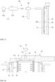
- FIG. 1 schematically illustrates a wire rod manufacturing apparatus according to an embodiment of the present disclosure.
- a wire rod manufacturing apparatus 10 of the embodiment includes a heating furnace 11 configured to heat provided billets B, a rolling unit 12 located at an outlet side of the heating furnace 11 and configured to roll the heated billets B, and a wire rod winding device 20 located at an outlet side of the rolling unit 12 and configured to wind the rolled wire rod W.
- a wire rod rolling process used to manufacture wire rods W by the wire rod manufacturing apparatus 10 is performed by heating billets B, which are manufactured in a steel making process or a billet making process, in the heating furnace 11 to a state suitable for hot rolling, obtaining a wire rod coil by gradually reducing cross-sections thereof to a desired size through a series of rolling processes in the rolling unit 12 including a rough mill and a finishing mill, transferring the wire rod coil to the wire rod winding device 20, and storing the coil in a wound state.
- FIG. 2 is a cross-sectional view illustrating a wire rod winding device according to an embodiment of the present disclosure.
- FIG. 3 is a perspective view illustrating a fork pin unit according to an embodiment of the present disclosure.
- FIG. 4 illustrates a dry ice supply unit according to an embodiment of the present disclosure.
- the wire rod winding device 20 includes a drum unit 30 having a double-drum structure, a fork pin unit 40 disposed inside the drum unit 30, a cover unit 50 to cover the top of the drum unit 30, a dry ice supply unit 60 configured to supply dry ice pellets to cool the drum unit 30, a drive unit 70 configured to rotate the drum unit 30, and a lifting unit 80 configured to discharge the stored wire rod to the outside.
- the drum unit 30 may have a container shape with an open top and a double-drum structure consisting of an outer drum 31 and an inner drum 32.
- the outer drum 31 may be spaced apart from the outer surface of the inner drum 32 at a predetermined interval in a shape surrounding the outer periphery of the outer surface of the inner drum 32. Dry ice pellets, which are supplied by the dry ice supply unit 60, are sprayed into a chamber 33 that is a space formed between the outer drum 31 and the inner drum 32.
- the inner drum 32 may be rotated by the drive unit 70.
- a shaft 34 connected to the drive unit 70 is provided at the lower end of the inner drum 32.
- the shaft 34 may penetrate the outer drum 31 and extend downward from the bottom of the outer drum 31.
- the lower end of the shaft 34 may be rotatably supported by a mount 71 supported by the floor.
- a bearing member 72 may be installed between the mount 71 and the lower end of the shaft 34 for smooth rotation of the shaft 34.
- the bearing member 72 includes a thrust bearing to reduce frictional resistance during rotation while supporting an axial load.
- a flange 35 extending outward in a radial direction is provided on the outer surface of the shaft 34 exposed to the outside of the outer drum 31 such that a driven bevel gear 73 is coupled thereto, and the driven bevel gear 73 may rotate in an engaged state with a drive bevel gear 75 coupled to a shaft of the drive motor 74.
- a shaft support 36 may be provided on the outer surface of the shaft 34 penetrating the outer drum 31 to reduce frictional resistance while the shaft 34 rotates.
- the shaft support 36 includes a bearing member such as sleeve bearing and rolling bearing to reduce frictional resistance of a member rotating on the other side.
- the fork pin unit 40 may be formed in the form of a plurality of vertically extending rods penetrating the bottom of the inner drum 32 and hollow flow channel holes 41 may be vertically formed inside the fork pin unit 40.
- the fork pin unit 40 integrally coupled to the inner drum 32 may rotate together with the inner drum 32 to guide winding of the wire rod.
- the wire rod introduced into the inner drum 32 may be wound and stored between the inner drum 32 and the fork pin unit 40.
- the chamber 33 may communicate with the inside of the inner drum 32.
- An open inlet 42 formed at the lower end of the flow channel hole 41 may be located inside the chamber 33, and an open outlet 43 formed at the upper end of the flow channel hole 41 may be located around the upper end of the inner drum 32.
- the inlet 42 of the flow channel hole 41 serves as an air suction port to suck dry ice pellets sprayed into the chamber 22 into the flow channel hole 41, and the outlet 43 of the flow channel hole 41 serves as an air discharge port to discharge sublimated carbon dioxide gas that has passed along the flow channel hole 41.
- connection rim 44 The upper end of the fork pin unit 40 formed in the form of the plurality of rods may be connected by a connection rim 44.
- Link coupling taps, bolting coupling taps, or the like for coupling with the fork pin unit 40 may be formed at the connection rim 44 in a circumferential direction.
- a plurality of cooling fins 45 spaced apart from each other at predetermined intervals may be formed on the fork pin unit 40 in the vertical direction.
- the cover unit 50 may cover the open top of the inner drum 32 to prevent heat loss from the top of the inner drum 32 by convection while winding the wire rod.
- the cover unit 50 may be configured as a moving heat-retaining cover.
- An anti-eccentric groove 51 to restrain eccentric rotation while the fork pin unit 40 rotates may be formed on the bottom surface of the cover unit 50 and the fork pin unit 40 may rotate in a state where the upper end of the fork pin unit 40 is accommodated in the anti-eccentric groove 51.
- the cover unit 50 may have a guide hole 52 for introducing the wire rod into the inner drum 32 while winding the wire rod.
- the guide hole 52 may be formed in an inclined direction corresponding to an entry direction of the wire rod such that the wire rod is stored in the inner drum 32 in a wound state.
- the dry ice supply unit 60 supplies dry ice particles into the chamber 33 formed between the outer drum 31 and the inner drum 32 and includes a compressed air supplier 61, a pellet supplier 62, and a plurality of spray nozzles 63.
- the compressed air supplier 61, the pellet supplier 62, and the plurality of spray nozzles 63 may be connected to each other via a dry ice supply line 64.
- the compressed air supplier 61 may include an air compressor 61a and a receiver tank 61b.
- the air compressor 61a may include a pump to generate compressed air, and the compressed air generated in the air compressor 61a may be supplied to the receiver tank 61b.
- the receiver tank 61b may perform a function of a buffer by temporarily storing the compressed air supplied from the air compressor 61a and may provide the stably compressed air toward the pellet supplier 62.
- the pellet supplier 62 provides dry ice pellets to the dry ice supply line 64 and includes a hopper 52a to store dry ice, and a feeder 62b to provide dry ice received from the hopper 62a to the dry ice supply line 64.
- the feeder 62b may include a screw conveyor or a rotating disk type for crushing dry ice into pellets, and the dry ice pellets provided from the feeder 62b to the dry ice supply line 64 may be transported to the plurality of spray nozzles 63 by the compressed air supplied by the compressed air supplier 61.
- the plurality of spray nozzles 63 may be connected to the dry ice supply line 64 and disposed at a vertically extending nozzle header 63a to be spaced apart from each other at predetermined intervals.
- the plurality of spray nozzles 63 may be configured to spray dry ice pellets into the chamber 33 and spaced apart from each other at predetermined intervals along the circumferential direction or a height direction of the drum unit 30.
- At least one spray nozzle 63b may be configured to selectively spray dry ice pellets toward the shaft support 36.
- the dry ice pellets sprayed to the shaft support 36 rapidly lower the temperature of contaminant particles adhered to the shaft support 36, and cracks are caused in the contaminant particles whose adhesion has been decreased by physical impact and rapid cooling, so that the contaminant particles are separated from the surface of the shaft support 36. Therefore, non-smooth rotation of the drum unit 30 caused by the contaminant particles adhered to the shaft support 36 may be prevented.
- FIG. 6 shows a dry ice supply unit according to another embodiment of the present disclosure.
- the same reference numerals are assigned to elements having substantially same function, and detailed descriptions thereof will be omitted.
- a dry ice supply unit 60 includes a liquefied carbon dioxide supplier 65 configured to supply liquefied carbon dioxide, an adiabatic expansion unit 66 configured to adiabatically expand the liquefied carbon dioxide received from the liquefied carbon dioxide supplier 65, a compressed air supplier 61 configured to provide compressed air that delivers dry ice pellets generated in the adiabatic expansion unit 66, and a plurality of spray nozzles 63 to spray dry ice pellets delivered by the compressed air into the chamber 33.
- the liquefied carbon dioxide supplied by the liquefied carbon dioxide supplier 65 is adiabatically expanded in the adiabatic expansion unit 66, dry ice pellets are generated, and the generated dry ice pellets may be supplied into the chamber 33 through a plurality of spray nozzles 63 using the compressed air generated in the compressed air supplier 61.
- the dry ice pellets sprayed via the plurality of spray nozzles 63 are introduced into the chamber 33 and then introduced into the flow channel hole 41 of the fork pin unit 40 through the inlet 42 of the fork pin unit 40 communicating with the chamber 33.
- the dry ice pellets introduced into the chamber 33 and the flow channel hole 41 instantly lower the temperature of the drum unit 30 and the fork pin unit 40 while sublimating and then are discharged through the outlet 43 of the fork pin unit 40.
- FIG. 7 illustrates a suction device connected to a cover unit according to an embodiment of the present disclosure.
- a suction device 90 providing a suction force for smoothly sucking the dry ice pellets filled in the chamber 33 toward the flow channel hole 41 may be connected to the cover unit 50 of the present embodiment.
- the suction device 90 is intended to induce an increase in the amount of the dry ice pellets introduced into the flow channel hole 41 even at a high rotation speed of the drum unit 30 and includes an air discharge flow channel 91 formed at the cover unit 50, a suction fan 92 providing a suction force, and a suction hose 93 connecting the suction fan 92 with the air discharge flow channel 91.
- An inlet 91a of the air discharge flow channel 91 may be installed to communicate with the outlet 43 of the fork pin unit 40, and an outlet 91b of the air discharge flow channel 91 may be connected to the suction hose 93.
- the inlet 91a of the air discharge flow channel 91 may be formed in a circular ring shape, and the outlet 43 and the connection rim 44 disposed at the upper end of the fork pin unit 40 may be in close contact with the inlet 91a.
- the inlet 91a of the air discharge flow channel 91 may perform the function of the anti-eccentric groove described above.
- FIG. 8 shows a cover unit according to another embodiment of the present disclosure.
- a heat dissipation plate 100 may be provided on the bottom of the cover unit 50 to discharge heat of the upper portion of the drum unit 30 to the outside.
- a temperature of a portion of the wire rod wound later at an upper portion of the drum unit 30 may be relatively higher than that of the wire rod wound earlier at a lower portion of the drum unit 30, and thus the heat dissipation plate 100 rapidly discharges heat of the upper portion of the drum unit 30 out of the cover unit 50. Therefore, while the wire rod is wound, a temperature deviation in the vertical direction inside the drum unit 30 may be reduced, thereby preventing deterioration in quality of the wire rod.
- the heat dissipation plate 100 may be formed of a metallic material having excellent thermal conductivity such as aluminum.
- the heat dissipation plate 100 includes a lower conduction part 101 disposed at the bottom surface of the cover unit 50 and receiving heat from the upper portion of the inside of the drum unit 30, an upper emission part 102 disposed at the top surface of the cover unit 50 to be exposed to the outside to emit heat, and a heat transfer part 103 connecting the upper emission part 102 with the lower conduction part 101 to transfer heat received from the lower conduction part 101 to the upper emission part 102.
- Heat dissipation protrusions 104 may be disposed on the upper emission part 102 to improve heat dissipation property by enlarging a contact area with external air.
- the lower conduction part 101 may have an anti-eccentric groove 51 to accommodate the upper end of the fork pin unit 40.
- heat of the upper portion of the inside of the drum unit 30 may be discharged to the outside through the heat dissipation protrusions 104 after being conducted to the upper emission part 102 through the lower conduction part 101 and the heat transfer part 103.
- the lifting unit 80 is intended to guide mounting of the wound wire rod in the inner drum 32 or discharge the stored wire rod coil to the outside and includes a support 81 to support the wire rod and an elevating member 82 to move the support 81 upward and downward.
- the elevating member 82 may move upward and downward in association with a hydraulic or pneumatic cylinder that extends and retracts.
- the cooling flow channel 83 communicating with the chamber 33 may be formed in the support 81.
- the cooling flow channel 83 may communicate with the chamber 33 through a hole 37 formed in the inner drum 32.
- the hole 37 formed in the inner drum 32 may be located to communicate with the cooling flow channel 83 of the support 81 when the support 81 is located at the lower end of the inner drum 32, and the support 81 may be cooled as dry ice pellets introduced into the channel 33 therethrough are supplied into the cooling flow channel 83 and sublimated.
- a plurality of holes may be formed at appropriate positions such that the cooling flow channel 83 communicates with the chamber 33 when the support 81 moves to mount the wire rod, and the plurality of holes may also be configured to be selectively opened and closed.
Landscapes
- Engineering & Computer Science (AREA)
- Mechanical Engineering (AREA)
- Chemical & Material Sciences (AREA)
- Physics & Mathematics (AREA)
- Thermal Sciences (AREA)
- Materials Engineering (AREA)
- Crystallography & Structural Chemistry (AREA)
- Metallurgy (AREA)
- Organic Chemistry (AREA)
- Winding, Rewinding, Material Storage Devices (AREA)
- Heat Treatment Of Strip Materials And Filament Materials (AREA)
- Chemical Kinetics & Catalysis (AREA)
- Combustion & Propulsion (AREA)
- General Engineering & Computer Science (AREA)
Abstract
Description
- The present disclosure relates to a wire rod winding device and a wire rod manufacturing apparatus including same.
- In general, wire rod rolling is a process of obtaining a wire rod coil having a desired size by heating billets, which are manufactured in a steel making process or a billet making process, to a state suitable for hot rolling and gradually reducing cross-sections thereof through a series of rolling processes.
- Since a wire rod manufactured by the wire rod rolling process has a full length of about 500 m to 10 km, it cannot be stored in a straight form, and thus products are obtained in the form of a coil and this process is called winding.
- A winding process is a process of winding the wire rod coil on a cylindrical apparatus called reeler which includes a drum unit constituting the external diameter of the reeler and a fork pin unit constituting the internal diameter, and the wire rod coil is wound in a space therebetween.
- In addition, in the case where the reeler rotates to wind the wire rod coil, the fork pin unit coupled to the bottom of the drum unit and extending upward eccentrically rotates because the upper end thereof, as a free end, shakes during rotation. Therefore, the fork pin unit causes friction with the wire rod coil, thereby causing problems such as scratches on the wire rod coil.
- Also, in the reeler, while a preceding portion of the wire rod entering in an earlier stage of the winding process is wound at a lower portion of the drum unit, a following portion of the wire rod entering in a later stage of the winding process is wound at an upper portion of the drum unit. Thus, there may be a temperature difference between the upper portion and the lower portion of the wire rod coil due to convection heat loss at an upper portion of the drum unit with an open top.
- Due to the difference in cooling rate between positions of the wire rod coil caused by the amount of heat loss inside the reeler, problems may occur in tensile strength of the wire rod coil and microstructural quality.
- Embodiments of the present disclosure provide a wire rod winding device capable of simplifying complex structural problems occurring in the case of using cooling water to cool the wire rod winding device and preventing quality deterioration caused while winding the wire rod coil, and a wire rod manufacturing apparatus including same.
- In accordance with an aspect of the present disclosure, a wire rod winding device includes: a drum unit including an outer drum and an inner drum spaced apart from the outer drum and rotated by a drive unit; a dry ice supply unit configured to supply dry ice pellets into a chamber formed between the outer drum and the inner drum; and a fork pin unit connected with the inner drum at one side for integral rotation with the inner drum and spaced apart from the inside of the inner drum at the other side to wind a wire rod, wherein the fork pin unit has a flow channel hole having an inlet communicating with the chamber at one end and an outlet communicating with the inside of the inner drum at the other end.
- A shaft of the inner drum rotated by the drive unit may be coupled to the outer drum in a penetrating state, and the dry ice supply unit may include at least one spray nozzle to spray dry ice pellets toward a shaft support between the shaft of the inner drum and the outer drum.
- The wire rod winding device may further include a cover unit covering the top of the drum unit and having a guide hole guiding introduction of the wire rod into a space between the inner drum and the fork pin unit.
- The cover unit may have an air discharge flow channel communicating with the outlet of the fork pin unit to discharge gas sublimated from the dry ice to the outside.
- The wire rod winding device may further include a suction device connected to the outlet of the air discharge flow channel to provide a suction force to the flow channel hole through the air discharge flow channel.
- The suction device may include a suction hose connected to the outlet of the air discharge flow channel and a suction fan connected to the suction hose to provide a suction force thereto.
- The dry ice supply unit may include a pellet supplier configured to store and discharge dry ice, a compressed air supplier configured to provide compressed air to deliver dry ice pellets discharged from the pellet supplier, and a plurality of nozzles configured to spray the dry ice pellets delivered by the compressed air into the chamber.
- The dry ice supply unit may include a liquefied carbon dioxide supplier configured to supply liquefied carbon dioxide, an adiabatic expansion unit configured to adiabatically expand the liquefied carbon dioxide received from the liquefied carbon dioxide supplier, a compressed air supplier configured to provide compressed air for delivering dry ice pellets generated in the adiabatic expansion unit, and a plurality of spray nozzles configured to spray dry ice pellets delivered by the compressed air into the chamber.
- A heat dissipation plate may be provided on the bottom of the cover unit to discharge heat of the upper portion of the drum unit to the outside.
- The heat dissipation plate may include a lower conduction part disposed at the bottom surface of the cover unit, an upper emission part disposed at the top surface of the cover unit and exposed to external air, and a heat transfer part connecting the lower conduction part with the upper emission part.
- The lower conduction part may have an anti-eccentric groove accommodating the upper end of the fork pin unit.
- The wire rod winding device may further include a support to support the wire rod at the inner side of the inner drum and including a cooling flow channel formed therein, wherein the cooling flow channel communicates with the chamber through a hole formed in the inner drum
- In accordance with another aspect of the present disclosure, a wire rod manufacturing apparatus includes: a heating furnace configured to heat provided billets; a rolling unit located at an outlet side of the heating furnace and configured to roll the heated billets; and the wire rod winding device disposed at an outlet side of the rolling unit and configured to wind a wire rod prepared by rolling the billets.
- According to the embodiments of the present disclosure, a structure for cooling the wire rod winding device may be simplified, and surface defects caused on the winding apparatus and the wire rod coil and quality deviation of the wire rod coil caused by a temperature difference between positions of the wire rod coil wound on the winding apparatus may be reduced.
-
-
FIG. 1 schematically illustrates a wire rod manufacturing apparatus according to an embodiment of the present disclosure. -
FIG. 2 is a cross-sectional view illustrating a wire rod winding device according to an embodiment of the present disclosure. -
FIG. 3 is a perspective view illustrating a fork pin unit according to an embodiment of the present disclosure. -
FIG. 4 illustrates a dry ice supply unit according to an embodiment of the present disclosure. -
FIG. 5 illustrates a part of a shaft support according to an embodiment of the present disclosure. -
FIG. 6 shows a dry ice supply unit according to another embodiment of the present disclosure. -
FIG. 7 illustrates a suction device of a cover unit according to an embodiment of the present disclosure. -
FIG. 8 shows a cover unit according to another embodiment of the present disclosure. -
FIG. 9 is a cross-sectional view illustrating a support according to an embodiment of the present disclosure. - Hereinafter, embodiments of the present disclosure will be described in detail with reference to the accompanying drawings. These embodiments are provided to fully convey the concept of the present disclosure to those of ordinary skill in the art. The present disclosure may, however, be embodied in many different forms and should not be construed as limited to the exemplary embodiments set forth herein. In the drawings, parts unrelated to the descriptions are omitted for clear description of the disclosure and widths, lengths, thicknesses, and the like of elements may be exaggerated for clarity. Throughout the specification, like reference numerals denote like elements.
-
FIG. 1 schematically illustrates a wire rod manufacturing apparatus according to an embodiment of the present disclosure. - Referring to
FIG. 1 , a wirerod manufacturing apparatus 10 of the embodiment includes aheating furnace 11 configured to heat provided billets B, arolling unit 12 located at an outlet side of theheating furnace 11 and configured to roll the heated billets B, and a wirerod winding device 20 located at an outlet side of the rollingunit 12 and configured to wind the rolled wire rod W. - As such, a wire rod rolling process used to manufacture wire rods W by the wire
rod manufacturing apparatus 10 is performed by heating billets B, which are manufactured in a steel making process or a billet making process, in theheating furnace 11 to a state suitable for hot rolling, obtaining a wire rod coil by gradually reducing cross-sections thereof to a desired size through a series of rolling processes in therolling unit 12 including a rough mill and a finishing mill, transferring the wire rod coil to the wirerod winding device 20, and storing the coil in a wound state. -
FIG. 2 is a cross-sectional view illustrating a wire rod winding device according to an embodiment of the present disclosure.FIG. 3 is a perspective view illustrating a fork pin unit according to an embodiment of the present disclosure. -
FIG. 4 illustrates a dry ice supply unit according to an embodiment of the present disclosure. - Referring to
FIGS. 2 to 4 , the wirerod winding device 20 includes adrum unit 30 having a double-drum structure, afork pin unit 40 disposed inside thedrum unit 30, acover unit 50 to cover the top of thedrum unit 30, a dryice supply unit 60 configured to supply dry ice pellets to cool thedrum unit 30, adrive unit 70 configured to rotate thedrum unit 30, and alifting unit 80 configured to discharge the stored wire rod to the outside. - The
drum unit 30 may have a container shape with an open top and a double-drum structure consisting of anouter drum 31 and aninner drum 32. - The
outer drum 31 may be spaced apart from the outer surface of theinner drum 32 at a predetermined interval in a shape surrounding the outer periphery of the outer surface of theinner drum 32. Dry ice pellets, which are supplied by the dryice supply unit 60, are sprayed into achamber 33 that is a space formed between theouter drum 31 and theinner drum 32. - The
inner drum 32 may be rotated by thedrive unit 70. Ashaft 34 connected to thedrive unit 70 is provided at the lower end of theinner drum 32. Theshaft 34 may penetrate theouter drum 31 and extend downward from the bottom of theouter drum 31. - The lower end of the
shaft 34 may be rotatably supported by amount 71 supported by the floor. Abearing member 72 may be installed between themount 71 and the lower end of theshaft 34 for smooth rotation of theshaft 34. The bearingmember 72 includes a thrust bearing to reduce frictional resistance during rotation while supporting an axial load. - A
flange 35 extending outward in a radial direction is provided on the outer surface of theshaft 34 exposed to the outside of theouter drum 31 such that a drivenbevel gear 73 is coupled thereto, and the drivenbevel gear 73 may rotate in an engaged state with adrive bevel gear 75 coupled to a shaft of thedrive motor 74. - A
shaft support 36 may be provided on the outer surface of theshaft 34 penetrating theouter drum 31 to reduce frictional resistance while theshaft 34 rotates. Theshaft support 36 includes a bearing member such as sleeve bearing and rolling bearing to reduce frictional resistance of a member rotating on the other side. - The
fork pin unit 40 may be formed in the form of a plurality of vertically extending rods penetrating the bottom of theinner drum 32 and hollowflow channel holes 41 may be vertically formed inside thefork pin unit 40. - The
fork pin unit 40 integrally coupled to theinner drum 32 may rotate together with theinner drum 32 to guide winding of the wire rod. The wire rod introduced into theinner drum 32 may be wound and stored between theinner drum 32 and thefork pin unit 40. - Via the flow channel holes 41 formed in the
fork pin unit 40, thechamber 33 may communicate with the inside of theinner drum 32. Anopen inlet 42 formed at the lower end of theflow channel hole 41 may be located inside thechamber 33, and anopen outlet 43 formed at the upper end of theflow channel hole 41 may be located around the upper end of theinner drum 32. - The
inlet 42 of theflow channel hole 41 serves as an air suction port to suck dry ice pellets sprayed into the chamber 22 into theflow channel hole 41, and theoutlet 43 of theflow channel hole 41 serves as an air discharge port to discharge sublimated carbon dioxide gas that has passed along theflow channel hole 41. - The upper end of the
fork pin unit 40 formed in the form of the plurality of rods may be connected by aconnection rim 44. Link coupling taps, bolting coupling taps, or the like for coupling with thefork pin unit 40 may be formed at theconnection rim 44 in a circumferential direction. - Also, a plurality of cooling
fins 45 spaced apart from each other at predetermined intervals may be formed on thefork pin unit 40 in the vertical direction. - The
cover unit 50 may cover the open top of theinner drum 32 to prevent heat loss from the top of theinner drum 32 by convection while winding the wire rod. Thecover unit 50 may be configured as a moving heat-retaining cover. - An
anti-eccentric groove 51 to restrain eccentric rotation while thefork pin unit 40 rotates may be formed on the bottom surface of thecover unit 50 and thefork pin unit 40 may rotate in a state where the upper end of thefork pin unit 40 is accommodated in theanti-eccentric groove 51. - The
cover unit 50 may have aguide hole 52 for introducing the wire rod into theinner drum 32 while winding the wire rod. Theguide hole 52 may be formed in an inclined direction corresponding to an entry direction of the wire rod such that the wire rod is stored in theinner drum 32 in a wound state. - The dry
ice supply unit 60 supplies dry ice particles into thechamber 33 formed between theouter drum 31 and theinner drum 32 and includes acompressed air supplier 61, apellet supplier 62, and a plurality ofspray nozzles 63. - The
compressed air supplier 61, thepellet supplier 62, and the plurality ofspray nozzles 63 may be connected to each other via a dryice supply line 64. - The
compressed air supplier 61 may include anair compressor 61a and areceiver tank 61b. Theair compressor 61a may include a pump to generate compressed air, and the compressed air generated in theair compressor 61a may be supplied to thereceiver tank 61b. - The
receiver tank 61b may perform a function of a buffer by temporarily storing the compressed air supplied from theair compressor 61a and may provide the stably compressed air toward thepellet supplier 62. - The
pellet supplier 62 provides dry ice pellets to the dryice supply line 64 and includes a hopper 52a to store dry ice, and afeeder 62b to provide dry ice received from thehopper 62a to the dryice supply line 64. - The
feeder 62b may include a screw conveyor or a rotating disk type for crushing dry ice into pellets, and the dry ice pellets provided from thefeeder 62b to the dryice supply line 64 may be transported to the plurality ofspray nozzles 63 by the compressed air supplied by thecompressed air supplier 61. - The plurality of
spray nozzles 63 may be connected to the dryice supply line 64 and disposed at a vertically extendingnozzle header 63a to be spaced apart from each other at predetermined intervals. - The plurality of
spray nozzles 63 may be configured to spray dry ice pellets into thechamber 33 and spaced apart from each other at predetermined intervals along the circumferential direction or a height direction of thedrum unit 30. - Referring to
FIG. 5 , among the plurality ofspray nozzles 63, at least onespray nozzle 63b may be configured to selectively spray dry ice pellets toward theshaft support 36. The dry ice pellets sprayed to theshaft support 36 rapidly lower the temperature of contaminant particles adhered to theshaft support 36, and cracks are caused in the contaminant particles whose adhesion has been decreased by physical impact and rapid cooling, so that the contaminant particles are separated from the surface of theshaft support 36. Therefore, non-smooth rotation of thedrum unit 30 caused by the contaminant particles adhered to theshaft support 36 may be prevented. -
FIG. 6 shows a dry ice supply unit according to another embodiment of the present disclosure. Hereinafter, the same reference numerals are assigned to elements having substantially same function, and detailed descriptions thereof will be omitted. - Referring to
FIG. 6 , a dryice supply unit 60 includes a liquefiedcarbon dioxide supplier 65 configured to supply liquefied carbon dioxide, anadiabatic expansion unit 66 configured to adiabatically expand the liquefied carbon dioxide received from the liquefiedcarbon dioxide supplier 65, acompressed air supplier 61 configured to provide compressed air that delivers dry ice pellets generated in theadiabatic expansion unit 66, and a plurality ofspray nozzles 63 to spray dry ice pellets delivered by the compressed air into thechamber 33.
while the liquefied carbon dioxide supplied by the liquefiedcarbon dioxide supplier 65 is adiabatically expanded in theadiabatic expansion unit 66, dry ice pellets are generated, and the generated dry ice pellets may be supplied into thechamber 33 through a plurality ofspray nozzles 63 using the compressed air generated in thecompressed air supplier 61. - Through this configuration, in the process of winding the wire rod performed by the wire
rod winding device 20, the dry ice pellets sprayed via the plurality ofspray nozzles 63 are introduced into thechamber 33 and then introduced into theflow channel hole 41 of thefork pin unit 40 through theinlet 42 of thefork pin unit 40 communicating with thechamber 33. - The dry ice pellets introduced into the
chamber 33 and theflow channel hole 41 instantly lower the temperature of thedrum unit 30 and thefork pin unit 40 while sublimating and then are discharged through theoutlet 43 of thefork pin unit 40. Thereby, in comparison with a case of using cooling water for cooling thedrum unit 30 and thefork pin unit 40, there is no need to install a separate structure to discharge cooling water and a sealing structure to prevent damage to peripheral parts caused by leakage of the cooling water. - Hereinafter, wire rod winding devices according to various embodiments of the present disclosure will be described. In the following descriptions, the same reference numerals will be assigned to elements having substantially same functions, and detailed descriptions thereof will be omitted.
-
FIG. 7 illustrates a suction device connected to a cover unit according to an embodiment of the present disclosure. Referring toFIG. 7 , asuction device 90 providing a suction force for smoothly sucking the dry ice pellets filled in thechamber 33 toward theflow channel hole 41 may be connected to thecover unit 50 of the present embodiment. - The
suction device 90 is intended to induce an increase in the amount of the dry ice pellets introduced into theflow channel hole 41 even at a high rotation speed of thedrum unit 30 and includes an airdischarge flow channel 91 formed at thecover unit 50, asuction fan 92 providing a suction force, and asuction hose 93 connecting thesuction fan 92 with the airdischarge flow channel 91. - An
inlet 91a of the airdischarge flow channel 91 may be installed to communicate with theoutlet 43 of thefork pin unit 40, and anoutlet 91b of the airdischarge flow channel 91 may be connected to thesuction hose 93. - The
inlet 91a of the airdischarge flow channel 91 may be formed in a circular ring shape, and theoutlet 43 and theconnection rim 44 disposed at the upper end of thefork pin unit 40 may be in close contact with theinlet 91a. In this regard, theinlet 91a of the airdischarge flow channel 91 may perform the function of the anti-eccentric groove described above. -
FIG. 8 shows a cover unit according to another embodiment of the present disclosure. - Referring to
FIG. 8 , aheat dissipation plate 100 may be provided on the bottom of thecover unit 50 to discharge heat of the upper portion of thedrum unit 30 to the outside. - While the wire rod is wound on the
drum unit 30, a temperature of a portion of the wire rod wound later at an upper portion of thedrum unit 30 may be relatively higher than that of the wire rod wound earlier at a lower portion of thedrum unit 30, and thus theheat dissipation plate 100 rapidly discharges heat of the upper portion of thedrum unit 30 out of thecover unit 50. Therefore, while the wire rod is wound, a temperature deviation in the vertical direction inside thedrum unit 30 may be reduced, thereby preventing deterioration in quality of the wire rod. - The
heat dissipation plate 100 may be formed of a metallic material having excellent thermal conductivity such as aluminum. Theheat dissipation plate 100 includes alower conduction part 101 disposed at the bottom surface of thecover unit 50 and receiving heat from the upper portion of the inside of thedrum unit 30, anupper emission part 102 disposed at the top surface of thecover unit 50 to be exposed to the outside to emit heat, and aheat transfer part 103 connecting theupper emission part 102 with thelower conduction part 101 to transfer heat received from thelower conduction part 101 to theupper emission part 102. -
Heat dissipation protrusions 104 may be disposed on theupper emission part 102 to improve heat dissipation property by enlarging a contact area with external air. - Meanwhile, in the case where the
cover unit 50 is provided with theheat dissipation plate 100, thelower conduction part 101 may have ananti-eccentric groove 51 to accommodate the upper end of thefork pin unit 40. - Through this configuration, heat of the upper portion of the inside of the
drum unit 30 may be discharged to the outside through theheat dissipation protrusions 104 after being conducted to theupper emission part 102 through thelower conduction part 101 and theheat transfer part 103. - Referring back to
FIG. 2 , the liftingunit 80 is intended to guide mounting of the wound wire rod in theinner drum 32 or discharge the stored wire rod coil to the outside and includes asupport 81 to support the wire rod and an elevatingmember 82 to move thesupport 81 upward and downward. The elevatingmember 82 may move upward and downward in association with a hydraulic or pneumatic cylinder that extends and retracts. - Meanwhile, referring to
FIG. 9 . Thecooling flow channel 83 communicating with thechamber 33 may be formed in thesupport 81. Thecooling flow channel 83 may communicate with thechamber 33 through ahole 37 formed in theinner drum 32. - The
hole 37 formed in theinner drum 32 may be located to communicate with thecooling flow channel 83 of thesupport 81 when thesupport 81 is located at the lower end of theinner drum 32, and thesupport 81 may be cooled as dry ice pellets introduced into thechannel 33 therethrough are supplied into thecooling flow channel 83 and sublimated. - Meanwhile, although one
hole 37 is formed in theinner drum 32 in the present embodiment, a plurality of holes may be formed at appropriate positions such that thecooling flow channel 83 communicates with thechamber 33 when thesupport 81 moves to mount the wire rod, and the plurality of holes may also be configured to be selectively opened and closed. - While the present disclosure has been particularly described with reference to exemplary embodiments, it should be understood by those of skilled in the art that the scope of the present disclosure is not limited thereby and various changes in form and details may be made without departing from the spirit and scope of the present disclosure.
Claims (13)
- A wire rod winding device comprising:a drum unit comprising an outer drum and an inner drum spaced apart from the outer drum and rotated by a drive unit;a dry ice supply unit configured to supply dry ice pellets into a chamber formed between the outer drum and the inner drum; anda fork pin unit connected with the inner drum at one side for integral rotation with the inner drum and spaced apart from the inside of the inner drum at the other side to wind a wire rod,wherein the fork pin unit has a flow channel hole having an inlet communicating with the chamber at one end and an outlet communicating with the inside of the inner drum at the other end.
- The wire rod winding device according to claim 1, wherein a shaft of the inner drum rotated by the drive unit is coupled to the outer drum in a penetrating state, and
the dry ice supply unit comprises at least one spray nozzle to spray dry ice pellets toward a shaft support between the shaft of the inner drum and the outer drum. - The wire rod winding device according to claim 1, further comprising a cover unit covering the top of the drum unit and having a guide hole guiding introduction of the wire rod into a space between the inner drum and the fork pin unit.
- The wire rod winding device according to claim 3, wherein the cover unit has an air discharge flow channel communicating with the outlet of the fork pin unit to discharge gas sublimated from the dry ice to the outside.
- The wire rod winding device according to claim 4, further comprising a suction device connected to the outlet of the air discharge flow channel to provide a suction force to the flow channel hole through the air discharge flow channel.
- The wire rod winding device according to claim 5, wherein the suction device comprises a suction hose connected to the outlet of the air discharge flow channel and a suction fan connected to the suction hose to provide a suction force thereto.
- The wire rod winding device according to claim 5, wherein the dry ice supply unit comprises a pellet supplier configured to store and discharge dry ice, a compressed air supplier configured to provide compressed air to deliver dry ice pellets discharged from the pellet supplier, and a plurality of nozzles configured to spray the dry ice pellets delivered by the compressed air into the chamber.
- The wire rod winding device according to claim 5, wherein the dry ice supply unit comprises a liquefied carbon dioxide supplier configured to supply liquefied carbon dioxide, an adiabatic expansion unit configured to adiabatically expand the liquefied carbon dioxide received from the liquefied carbon dioxide supplier, a compressed air supplier configured to provide compressed air for delivering dry ice pellets generated in the adiabatic expansion unit, and a plurality of spray nozzles configured to spray dry ice pellets delivered by the compressed air into the chamber.
- The wire rod winding device according to claim 3, wherein a heat dissipation plate is provided on the bottom of the cover unit to discharge heat of the upper portion of the drum unit to the outside.
- The wire rod winding device according to claim 9, wherein the heat dissipation plate comprises a lower conduction part disposed at the bottom surface of the cover unit, an upper emission part disposed at the top surface of the cover unit and exposed to external air, and a heat transfer part connecting the lower conduction part with the upper emission part.
- The wire rod winding device according to claim 10, wherein the lower conduction part has an anti-eccentric groove accommodating the upper end of the fork pin unit.
- The wire rod winding device according to claim 1, further comprising a support to support the wire rod at the inner side of the inner drum and including a cooling flow channel formed therein,
wherein the cooling flow channel communicates with the chamber through a hole formed in the inner drum. - A wire rod manufacturing apparatus comprising:a heating furnace configured to heat provided billets;a rolling unit located at an outlet side of the heating furnace and configured to roll the heated billets; andthe wire rod winding device according to any one of claims 1 to 12 disposed at an outlet side of the rolling unit and configured to wind a wire rod prepared by rolling the billets.
Applications Claiming Priority (2)
| Application Number | Priority Date | Filing Date | Title |
|---|---|---|---|
| KR1020200103519A KR102326259B1 (en) | 2020-08-18 | 2020-08-18 | Wire coiling unit and wire manufacturing apparaus having the same |
| PCT/KR2020/016293 WO2022039325A1 (en) | 2020-08-18 | 2020-11-18 | Wire rod winding device and wire rod manufacturing apparatus comprising same |
Publications (4)
| Publication Number | Publication Date |
|---|---|
| EP4176986A1 true EP4176986A1 (en) | 2023-05-10 |
| EP4176986A4 EP4176986A4 (en) | 2023-12-20 |
| EP4176986C0 EP4176986C0 (en) | 2025-12-31 |
| EP4176986B1 EP4176986B1 (en) | 2025-12-31 |
Family
ID=78716779
Family Applications (1)
| Application Number | Title | Priority Date | Filing Date |
|---|---|---|---|
| EP20950405.9A Active EP4176986B1 (en) | 2020-08-18 | 2020-11-18 | Rolled wire winding device and rolled wire manufacturing device with which |
Country Status (5)
| Country | Link |
|---|---|
| EP (1) | EP4176986B1 (en) |
| JP (1) | JP7545572B2 (en) |
| KR (1) | KR102326259B1 (en) |
| CN (1) | CN115989097A (en) |
| WO (1) | WO2022039325A1 (en) |
Family Cites Families (16)
| Publication number | Priority date | Publication date | Assignee | Title |
|---|---|---|---|---|
| DE1239651B (en) * | 1965-01-28 | 1967-05-03 | Verwaltungsgesellschaft Moelle | Wire reel with water cooling |
| DE2435830C3 (en) * | 1974-07-25 | 1981-11-05 | ARBED-F & G Drahtwerke Köln GmbH, 5000 Köln | Method and device for the production of steel wire |
| JPH0689412B2 (en) * | 1988-04-04 | 1994-11-09 | 新日本製鐵株式会社 | Steel wire drawing method |
| JPH0384378A (en) * | 1989-08-28 | 1991-04-09 | Sumitomo Metal Ind Ltd | Cooling method for high temperature body |
| JP3400116B2 (en) * | 1994-07-14 | 2003-04-28 | 石川島播磨重工業株式会社 | Winding device |
| JPH09263833A (en) * | 1996-03-29 | 1997-10-07 | Showa Alum Corp | Cooling method of extruded profile |
| KR200275554Y1 (en) * | 1997-12-24 | 2002-10-31 | 주식회사 포스코 | Bine coil winding device of wire rod production line |
| JP2006139204A (en) * | 2004-11-15 | 2006-06-01 | Tokai Rubber Ind Ltd | Roll playback method and its roll |
| KR100685047B1 (en) * | 2005-12-12 | 2007-02-20 | 주식회사 포스코 | Blowing and moisture cooling device for wire rod coil |
| KR101207735B1 (en) * | 2010-05-26 | 2012-12-03 | 주식회사 포스코 | Apparatus for coiling a wire |
| KR101197808B1 (en) * | 2010-11-12 | 2012-11-05 | 주식회사 포스코 | Apparatus for winding wire rod |
| JP2013169562A (en) * | 2012-02-20 | 2013-09-02 | Mitsubishi Heavy Ind Ltd | Method of removing scale of steel and method of manufacturing rolled steel plate |
| CN206882765U (en) * | 2017-06-16 | 2018-01-16 | 中冶京诚(扬州)冶金科技产业有限公司 | A kind of device for directionally solidifying for heater for rolling steel heat-resistant bearer |
| CN208440524U (en) * | 2018-06-20 | 2019-01-29 | 江苏永鼎光纤科技有限公司 | A kind of optical fiber cooling apparatus |
| KR102098499B1 (en) | 2018-09-28 | 2020-04-07 | 주식회사 포스코 | Wire coiling unit and wire manufacturing apparatus having thereof |
| CN109649353B (en) * | 2018-12-28 | 2024-02-13 | 厦门理工学院 | Vehicle-mounted cooling device and cooling method adopting dry ice |
-
2020
- 2020-08-18 KR KR1020200103519A patent/KR102326259B1/en active Active
- 2020-11-18 EP EP20950405.9A patent/EP4176986B1/en active Active
- 2020-11-18 JP JP2023511914A patent/JP7545572B2/en active Active
- 2020-11-18 WO PCT/KR2020/016293 patent/WO2022039325A1/en not_active Ceased
- 2020-11-18 CN CN202080103178.2A patent/CN115989097A/en active Pending
Also Published As
| Publication number | Publication date |
|---|---|
| KR102326259B1 (en) | 2021-11-16 |
| EP4176986A4 (en) | 2023-12-20 |
| JP7545572B2 (en) | 2024-09-04 |
| JP2023538070A (en) | 2023-09-06 |
| WO2022039325A1 (en) | 2022-02-24 |
| CN115989097A (en) | 2023-04-18 |
| EP4176986C0 (en) | 2025-12-31 |
| EP4176986B1 (en) | 2025-12-31 |
Similar Documents
| Publication | Publication Date | Title |
|---|---|---|
| US8652370B2 (en) | Hot isostatic pressing method and apparatus | |
| EP4176986B1 (en) | Rolled wire winding device and rolled wire manufacturing device with which | |
| CN207026489U (en) | A kind of metal centrifugal atomizing powder high-speed centrifugal atomization device | |
| CN207091550U (en) | A kind of material delivery system and crystal growth system | |
| US10611115B2 (en) | Tank cooling device | |
| KR101870678B1 (en) | A air-caster transporting device of elastic supporting type for precision equipments | |
| CN222434573U (en) | A heat preservation and transportation device for hot coiling of wire rods | |
| US6471509B2 (en) | Strip guiding device comprising a rotatable construction for changing supporting rolls having cooling means | |
| EP3364041A1 (en) | Fan blade and corresponding fan | |
| KR101242956B1 (en) | Wire-rod Coil Cooling Apparatus | |
| JP2010107193A (en) | Heat treatment apparatus | |
| CN116676472B (en) | Intelligent heat treatment production line | |
| KR102449781B1 (en) | Steel plate elevating device of roller table for transporting iron plate and roller table including the same | |
| CN116294571B (en) | High-temperature material pretreatment chute | |
| KR101629212B1 (en) | Dryer for drawing oil of drawing pipe | |
| CN113894934B (en) | Thermal insulation transportation method for tropical concrete | |
| KR102098499B1 (en) | Wire coiling unit and wire manufacturing apparatus having thereof | |
| CN119265471B (en) | High-strength stainless steel, manufacturing method and system thereof | |
| US20250230009A1 (en) | Heat treatment apparatus and guide roller for heat treatment apparatus | |
| CN219994200U (en) | Bearing cooling device for tightener | |
| CN212238622U (en) | Micro-tension reducing rolling structure for large-caliber stainless steel welded pipe | |
| US20150027140A1 (en) | System to Improve Icing Problems in Blast Freezer Tunnels | |
| KR101743705B1 (en) | Inner case latent heat cooling system for kimchi refrigerator | |
| CN216655023U (en) | High-purity target vacuum spraying device | |
| CN221231284U (en) | Mandrel cooling device |
Legal Events
| Date | Code | Title | Description |
|---|---|---|---|
| STAA | Information on the status of an ep patent application or granted ep patent |
Free format text: STATUS: THE INTERNATIONAL PUBLICATION HAS BEEN MADE |
|
| PUAI | Public reference made under article 153(3) epc to a published international application that has entered the european phase |
Free format text: ORIGINAL CODE: 0009012 |
|
| STAA | Information on the status of an ep patent application or granted ep patent |
Free format text: STATUS: REQUEST FOR EXAMINATION WAS MADE |
|
| 17P | Request for examination filed |
Effective date: 20230202 |
|
| AK | Designated contracting states |
Kind code of ref document: A1 Designated state(s): AL AT BE BG CH CY CZ DE DK EE ES FI FR GB GR HR HU IE IS IT LI LT LU LV MC MK MT NL NO PL PT RO RS SE SI SK SM TR |
|
| DAV | Request for validation of the european patent (deleted) | ||
| DAX | Request for extension of the european patent (deleted) | ||
| A4 | Supplementary search report drawn up and despatched |
Effective date: 20231121 |
|
| RIC1 | Information provided on ipc code assigned before grant |
Ipc: F25D 3/12 20060101ALI20231115BHEP Ipc: B21C 47/26 20060101ALI20231115BHEP Ipc: B21C 47/04 20060101AFI20231115BHEP |
|
| STAA | Information on the status of an ep patent application or granted ep patent |
Free format text: STATUS: EXAMINATION IS IN PROGRESS |
|
| 17Q | First examination report despatched |
Effective date: 20241022 |
|
| GRAP | Despatch of communication of intention to grant a patent |
Free format text: ORIGINAL CODE: EPIDOSNIGR1 |
|
| STAA | Information on the status of an ep patent application or granted ep patent |
Free format text: STATUS: GRANT OF PATENT IS INTENDED |
|
| INTG | Intention to grant announced |
Effective date: 20250626 |
|
| GRAS | Grant fee paid |
Free format text: ORIGINAL CODE: EPIDOSNIGR3 |
|
| GRAA | (expected) grant |
Free format text: ORIGINAL CODE: 0009210 |
|
| STAA | Information on the status of an ep patent application or granted ep patent |
Free format text: STATUS: THE PATENT HAS BEEN GRANTED |
|
| AK | Designated contracting states |
Kind code of ref document: B1 Designated state(s): AL AT BE BG CH CY CZ DE DK EE ES FI FR GB GR HR HU IE IS IT LI LT LU LV MC MK MT NL NO PL PT RO RS SE SI SK SM TR |
|
| REG | Reference to a national code |
Ref country code: CH Ref legal event code: F10 Free format text: ST27 STATUS EVENT CODE: U-0-0-F10-F00 (AS PROVIDED BY THE NATIONAL OFFICE) Effective date: 20251231 Ref country code: GB Ref legal event code: FG4D |
|
| REG | Reference to a national code |
Ref country code: DE Ref legal event code: R096 Ref document number: 602020065001 Country of ref document: DE |
|
| REG | Reference to a national code |
Ref country code: IE Ref legal event code: FG4D |
|
| U01 | Request for unitary effect filed |
Effective date: 20260121 |
|
| U07 | Unitary effect registered |
Designated state(s): AT BE BG DE DK EE FI FR IT LT LU LV MT NL PT RO SE SI Effective date: 20260128 |
|
| PG25 | Lapsed in a contracting state [announced via postgrant information from national office to epo] |
Ref country code: NO Free format text: LAPSE BECAUSE OF FAILURE TO SUBMIT A TRANSLATION OF THE DESCRIPTION OR TO PAY THE FEE WITHIN THE PRESCRIBED TIME-LIMIT Effective date: 20260331 |
|
| PG25 | Lapsed in a contracting state [announced via postgrant information from national office to epo] |
Ref country code: HR Free format text: LAPSE BECAUSE OF FAILURE TO SUBMIT A TRANSLATION OF THE DESCRIPTION OR TO PAY THE FEE WITHIN THE PRESCRIBED TIME-LIMIT Effective date: 20251231 |
|
| PG25 | Lapsed in a contracting state [announced via postgrant information from national office to epo] |
Ref country code: RS Free format text: LAPSE BECAUSE OF FAILURE TO SUBMIT A TRANSLATION OF THE DESCRIPTION OR TO PAY THE FEE WITHIN THE PRESCRIBED TIME-LIMIT Effective date: 20260331 |