EP4176954A1 - Filtration system with dual lip seal - Google Patents
Filtration system with dual lip seal Download PDFInfo
- Publication number
- EP4176954A1 EP4176954A1 EP22210306.1A EP22210306A EP4176954A1 EP 4176954 A1 EP4176954 A1 EP 4176954A1 EP 22210306 A EP22210306 A EP 22210306A EP 4176954 A1 EP4176954 A1 EP 4176954A1
- Authority
- EP
- European Patent Office
- Prior art keywords
- filter element
- seal member
- lip seal
- endplate
- protrusion
- Prior art date
- Legal status (The legal status is an assumption and is not a legal conclusion. Google has not performed a legal analysis and makes no representation as to the accuracy of the status listed.)
- Granted
Links
Images

Classifications
-
- B—PERFORMING OPERATIONS; TRANSPORTING
- B01—PHYSICAL OR CHEMICAL PROCESSES OR APPARATUS IN GENERAL
- B01D—SEPARATION
- B01D29/00—Filters with filtering elements stationary during filtration, e.g. pressure or suction filters, not covered by groups B01D24/00 - B01D27/00; Filtering elements therefor
- B01D29/01—Filters with filtering elements stationary during filtration, e.g. pressure or suction filters, not covered by groups B01D24/00 - B01D27/00; Filtering elements therefor with flat filtering elements
-
- B—PERFORMING OPERATIONS; TRANSPORTING
- B01—PHYSICAL OR CHEMICAL PROCESSES OR APPARATUS IN GENERAL
- B01D—SEPARATION
- B01D35/00—Filtering devices having features not specifically covered by groups B01D24/00 - B01D33/00, or for applications not specifically covered by groups B01D24/00 - B01D33/00; Auxiliary devices for filtration; Filter housing constructions
- B01D35/14—Safety devices specially adapted for filtration; Devices for indicating clogging
- B01D35/153—Anti-leakage or anti-return valves
-
- B—PERFORMING OPERATIONS; TRANSPORTING
- B01—PHYSICAL OR CHEMICAL PROCESSES OR APPARATUS IN GENERAL
- B01D—SEPARATION
- B01D29/00—Filters with filtering elements stationary during filtration, e.g. pressure or suction filters, not covered by groups B01D24/00 - B01D27/00; Filtering elements therefor
-
- B—PERFORMING OPERATIONS; TRANSPORTING
- B01—PHYSICAL OR CHEMICAL PROCESSES OR APPARATUS IN GENERAL
- B01D—SEPARATION
- B01D29/00—Filters with filtering elements stationary during filtration, e.g. pressure or suction filters, not covered by groups B01D24/00 - B01D27/00; Filtering elements therefor
- B01D29/0095—Flat filtering elements
-
- B—PERFORMING OPERATIONS; TRANSPORTING
- B01—PHYSICAL OR CHEMICAL PROCESSES OR APPARATUS IN GENERAL
- B01D—SEPARATION
- B01D29/00—Filters with filtering elements stationary during filtration, e.g. pressure or suction filters, not covered by groups B01D24/00 - B01D27/00; Filtering elements therefor
- B01D29/11—Filters with filtering elements stationary during filtration, e.g. pressure or suction filters, not covered by groups B01D24/00 - B01D27/00; Filtering elements therefor with bag, cage, hose, tube, sleeve or like filtering elements
- B01D29/13—Supported filter elements
- B01D29/15—Supported filter elements arranged for inward flow filtration
- B01D29/21—Supported filter elements arranged for inward flow filtration with corrugated, folded or wound sheets
-
- B—PERFORMING OPERATIONS; TRANSPORTING
- B01—PHYSICAL OR CHEMICAL PROCESSES OR APPARATUS IN GENERAL
- B01D—SEPARATION
- B01D35/00—Filtering devices having features not specifically covered by groups B01D24/00 - B01D33/00, or for applications not specifically covered by groups B01D24/00 - B01D33/00; Auxiliary devices for filtration; Filter housing constructions
- B01D35/16—Cleaning-out devices, e.g. for removing the cake from the filter casing or for evacuating the last remnants of liquid
-
- B—PERFORMING OPERATIONS; TRANSPORTING
- B01—PHYSICAL OR CHEMICAL PROCESSES OR APPARATUS IN GENERAL
- B01D—SEPARATION
- B01D2201/00—Details relating to filtering apparatus
- B01D2201/04—Supports for the filtering elements
- B01D2201/0415—Details of supporting structures
-
- B—PERFORMING OPERATIONS; TRANSPORTING
- B01—PHYSICAL OR CHEMICAL PROCESSES OR APPARATUS IN GENERAL
- B01D—SEPARATION
- B01D2201/00—Details relating to filtering apparatus
- B01D2201/29—Filter cartridge constructions
- B01D2201/291—End caps
-
- B—PERFORMING OPERATIONS; TRANSPORTING
- B01—PHYSICAL OR CHEMICAL PROCESSES OR APPARATUS IN GENERAL
- B01D—SEPARATION
- B01D2201/00—Details relating to filtering apparatus
- B01D2201/30—Filter housing constructions
- B01D2201/301—Details of removable closures, lids, caps, filter heads
- B01D2201/304—Seals or gaskets
-
- B—PERFORMING OPERATIONS; TRANSPORTING
- B01—PHYSICAL OR CHEMICAL PROCESSES OR APPARATUS IN GENERAL
- B01D—SEPARATION
- B01D2201/00—Details relating to filtering apparatus
- B01D2201/31—Other construction details
- B01D2201/316—Standpipes
-
- B—PERFORMING OPERATIONS; TRANSPORTING
- B01—PHYSICAL OR CHEMICAL PROCESSES OR APPARATUS IN GENERAL
- B01D—SEPARATION
- B01D2201/00—Details relating to filtering apparatus
- B01D2201/34—Seals or gaskets for filtering elements
- B01D2201/347—Radial sealings
-
- B—PERFORMING OPERATIONS; TRANSPORTING
- B01—PHYSICAL OR CHEMICAL PROCESSES OR APPARATUS IN GENERAL
- B01D—SEPARATION
- B01D2201/00—Details relating to filtering apparatus
- B01D2201/40—Special measures for connecting different parts of the filter
- B01D2201/4046—Means for avoiding false mounting of different parts
- B01D2201/4053—Means for avoiding false mounting of different parts using keys
Definitions
- the present application relates to filtration systems. More particularly, the present application relates to fluid filtration systems having a replaceable filter element.
- Fluid filtration systems are used to provide clean fluid to a device.
- internal combustion engines may have multiple filtration systems to provide clean fuel, clean oil, and clean fluid (e.g., liquid, air, hydraulic, etc.) to the various components of the internal combustion engines.
- Each filtration system generally includes a filter element having a filter media that filters the fluid.
- Some filtration systems such as fuel and oil filtration systems, often use replaceable filter elements that require periodic filter element replacement services to ensure proper filtration of the fluids.
- the filter element can remain immersed in the fluid to be filtered even when not in use. For example, after operation of an internal combustion engine has ceased, residual fuel to be filtered by a fuel filter element may remain in the filter element housing. In such situations, the residual fuel may spill from the filtration system during removal of the housing (e.g., removal of a housing that contains the filter element) or removal of the filter element from the housing during a service operation to change the filter element.
- Filter elements e.g., filter cartridges
- Filter elements often include a seal member that is compressed against a component of the filtration system housing or another portion of the filtration system.
- the seal member forms a seal between the filtration system housing and the filter element, thereby preventing fluid from bypassing the filter elements (e.g., for air to bypass an air filter element or liquid to bypass a liquid filter element).
- an improper filter element i.e., a non-authorized or non-genuine filter element
- the seal member of the filter element may not form a proper seal, and fluid may bypass the filter element, causing damage to downstream components or a drop in operating pressure. Accordingly, the installation of an improper filter element can harm critical components in the filtration system, cause improper sealing, diminish emission compliance mechanisms, cause subpar performance, and the like.
- the filtration system includes a housing having a drain.
- a filter element is positioned within the housing.
- the filter element includes a first endplate and a second endplate.
- Filter media is positioned between the first endplate and second endplate.
- a dual lip seal member is coupled to the second endplate.
- the dual lip seal member comprises a first protrusion that extends radially outward around an outer surface of the dual lip seal member.
- a second protrusion extends radially outward around the outer surface of the dual lip seal member.
- the dual lip seal member is configured to prevent fluid to be filtered from exiting the housing through the drain when the filter element is in an installed position.
- the dual lip seal member permits residual fluid to exit the housing through the drain when the filter element is displaced from the installed position.
- the filter element includes a first endplate and a second endplate. Filter media is positioned between the first endplate and second endplate.
- a dual lip seal member is coupled to the second endplate.
- the dual lip seal member comprises a first protrusion that extends radially outward around an outer surface of the dual lip seal member.
- a second protrusion extends radially outward around the outer surface of the dual lip seal member.
- the dual lip seal member is configured to prevent fluid to be filtered from exiting through a drain when the filter element is in an installed position in a housing.
- the dual lip seal member permits residual fluid to exit through the drain when the filter element is displaced from the installed position.
- various embodiments disclosed herein relate to a filtration system with a filter element that includes a dual lip seal (e.g., a dual lip seal member) that functions as an anti-drain seal.
- the dual lip seal member prevents fluid (e.g., fuel) being filtered from flowing back to a fluid storage tank (e.g., a fuel tank) through a drain in the filter housing when the filter element is in an installed position within the filter housing.
- the dual lip seal member prevents the dirty (e.g., yet to be filtered) fluid traveling through the inlet from flowing into the fluid storage tank.
- the configuration of the dual lip seal member with the filter housing allows fluid to flow back to the fluid storage tank when the filter element is being removed from the filter housing (e.g., during a filter change service). Additionally, the dual lip seal member prevents fuel on the dirty side (e.g., inlet) of the filter element from entering a water sump of the filtration system, thereby eliminating the need for a separate seal member.
- Non-compatible filter elements without the dual lip seal member will permit fluid to return to the fluid tank when the non-compatible filter element is installed in the filtration system. Since the fuel returns to the tank when the engine is off, the lack of fuel will cause a hard engine start when the engine is being restarted.
- the dual lip seal member also functions as an engine integrity protection mechanism, helping to ensure that an installed filter element is genuine (i.e., authorized, Original Equipment Manufacturer (“OEM”) approved, etc.).
- OEM Original Equipment Manufacturer
- the dual lip seal member performs multiple functions (anti-drain back to tank functions, draining functions, and engine integrity protection functions), thereby reducing the cost over traditional filter elements that require three separate components for each of the functions.
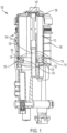
- FIG. 1 a cross-sectional view of a filtration system 100 that includes a filter element 104 with a dual lip seal member 102 is shown, according to an example embodiment.
- the filtration system includes a filter element 104, a complementary housing 106, and a filter mounting head 103.
- the filter element 104 is installed in an interior compartment of a housing 106 in an installed position (i.e., in an operational position that permits filtering of the fluid).
- the filter element 104 is connected to a filter mounting head (e.g., as described above) and the housing 106 is also attached to the filter mounting head 103 (e.g., via a threaded connection in arrangements where the housing 106 is a spin-on housing).
- the filter element 104 includes a dual lip seal member 102 that forms a radial seal between the filtration system housing 106 and the filter element 104, thereby preventing fluid from bypassing the filter element 104.
- the dual lip seal member 102 forms a seal between the housing 106 and the filter element 104.
- the dual lip seal member 102 prevents the fluid from exiting the housing 106 through the drain passage 118.
- an improper filter element i.e., a non-authorized or non-genuine filter element
- the dual lip seal member 102 of the filter element 104 may not form a proper seal, and fluid may bypass the filter element 104 causing damage to downstream components or improper operation of the filtration system 100 or other components.
- the filter element 104 includes a first endplate 108, a second endplate 110, filter media 112, and the dual lip seal member 102.
- the filter element 104 may be a cylindrical filter element with similarly shaped components.
- the filter media 112 includes an inner clean (e.g., filtered fuel) side 116 and an outer dirty (e.g. unfiltered fuel) side 114. Accordingly, the filter element 104 is an outside-in flow filter element.
- the filter element 104 is an inside-out flow filter element having an inner dirty side 114 and an outer clean side 116. Fluid to be filtered passes from the dirty side 114 of the filter media 112 to the clean side of the filter media 112.
- the filter media 112 may include any of paper-based filter media, fiber-based filter media, foam-based filter media, or the like.
- the filter media 112 is disposed between the first endplate 108 and the second endplate 110.
- the first endplate 108 is coupled to a first, top end of the filter media 112.
- the first endplate 108 may include a plurality of retention tabs to secure the filter element 104 to a filter mounting head of the filtration system 100 when the filter element 104 is installed in the filtration system 100.
- the retention tabs may form a snap-fit connection with the filter mounting head 103 of the filtration system 100 as the filter element 104 is installed in the filtration system 100.
- the retention tabs removably secure the filter element 104 to the mounting head during removal of the housing 106 of the filtration system 100, thereby permitting residual fluid in the housing to drain past the dual lip seal member 102 back into a fluid storage tank.
- the filter element 104 further includes a second endplate 110 coupled to a second, bottom end of the filter media 112.
- the second endplate 110 includes a central opening.
- the central opening is sized and shaped to receive a component of a filtration system (e.g., a standpipe) when the filter element 104 is installed in an operating position within the filtration system.
- the central opening is in fluid communication with a water sump.
- the first endplate 108 may also include a central opening.
- the central opening may route fluid and air to a component (e.g., to an internal combustion engine).
- the central opening may be configured to be in fluid communication with a center housing portion 126 of the housing 106.
- the filter element 104 includes a dual lip seal member 102.
- the dual lip seal member 102 is configured as an anti-drain dual lip seal member.
- the dual lip seal member 102 includes a central opening 120, a first protrusion 122, and a second protrusion 124.
- the dual lip seal member 102 comprises a cylindrical seal member with the first protrusion 122 and second protrusion 124 being disposed around the outer surface of the seal member 102.
- the dual lip seal member 102 is disposed adjacent to the drain passage 118 in the housing 106 that is in fluid communication with the fluid storage tank (not shown).
- the dual seal member may be formed concentrically (e.g., having a common center) with the filtration system 100 or eccentrically (e.g., not having a common center) with the filtration system 100 (as shown below in FIGS. 4A-4B ).
- the dual lip seal member 102 is coupled to the second endplate 110.
- the dual lip seal member 102 is disposed around an outer surface of the second endplate 110, the outer surface extending axially away from a bottom surface of the second endplate 110 away from the first endplate 108.
- the dual lip seal member 102 and the second endplate 110 may be manufactured as a single, integrated piece (e.g., via an over molding or heat staking process).
- the second endplate 110 includes a retaining member, such that a snap-fit connection is formed between the retaining member and central opening 120 of the dual lip seal member 102.
- the snap-fit connection removably secures the dual lip seal member 102 to the second endplate 110.
- the central opening 120 of the dual lip seal member 102 is aligned with a central opening that is configured to allow a component (e.g., the standpipe) to be received through the central opening 120 of the dual lip seal member 102.
- the first protrusion 122 and the second protrusion 124 provide a radial seal with both the top and bottom side of the second endplate 110.
- the dual lip seal member 102 includes two different lip seal diameters, as the first protrusion 122 has a first diameter and the second protrusion 124 has a second diameter. Accordingly, the diameters of the first protrusion 122 and the second protrusion 124 may be adjusted to provide ease of installation of the filter element 104 into the housing 106. This ensures that the assembly of the filter element 104 and housing 106 is successful only when the filter element 104 and housing 106 are properly aligned (e.g., sealed).
- the first diameter and the second diameter may be substantially similar. In other embodiments, the first diameter and the second diameter are different diameters.
- the dual lip seal member 102 includes a first protrusion 122 and a second protrusion 124 comprising a generally sideways 'v'-shape, with the center 130 of the dual lip seal (e.g., the indention of the tip of the 'v' shape) being adjacent to the drain passage 118.
- the first protrusion 122 and the second protrusion 124 extend around the outer surface around the dual lip seal member 102.
- the first protrusion 122 extends at a substantially 45-degree angle above a horizontal axis and the second protrusion extends at a substantially 45-degree angle below the horizontal axis, where the horizontal axis is parallel to the horizontal surface of the second endplate 110.
- the dual lip seal member 102 is shown having two protrusions in a generally sideways 'v'-shape, a wide variety of configurations may be implemented including variations in the shape of the dual lip seal member 102, size of dual lip seal member 102, and number of protrusions of the dual lip seal member 102.
- the dual lip seal member 102 is configured to have a shape, length, width, and number of elements that is specifically tailored to interface with an inner surface of the housing 106.
- the dual lip seal member 102 may comprise two separate O-rings, multiple lips, or other various shapes and configurations involving one or more lips and O-rings. This ensures that the assembly of the filter element 104 and housing 106 is successful only when the filter element 104 and housing 106 are properly aligned (e.g., sealed) and ensure engine integrity (e.g., genuine filter element 104).
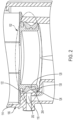
- FIG. 2 a cross-sectional view of the dual lip seal member 102 of the filtration system 100 of FIG. 1 is shown.
- FIG. 2 shows the area of the filter element 104 near the second endplate 110.
- the first protrusion 122 of the dual lip seal member 102 presses against a first portion 202 of an inner surface of the housing 106 and the second protrusion 124 of the dual lip seal member 102 presses against a lower, second portion 204 of the inner surface of the housing 106.
- the drain passage 118 is located between the first protrusion 122 and the second protrusion 124 and adjacent the base formed by the first protrusion 122 and second protrusion 124.
- the first protrusion 122 and the second protrusion 124 create a one-way valve, allowing the fluid to enter the housing 106 and preventing the fluid from returning back to the fluid storage tank.
- the dual lip seal member 102 prevents fluid to be filtered from exiting through a drain passage 118 located in the housing 106 while the filter element 104 is received in the installed position within the housing 106.
- the drain passage 118 connects the housing 106 to a fluid storage tank (e.g., the fuel tank of a vehicle powered by the internal combustion engine).
- the dual lip seal member 102 functions as an anti-drain back to the storage tank when the filter element 104 is installed in the housing 106 (e.g., between filter service operations).
- FIG. 3 shows a close-up cross-sectional view of the dual lip seal member 102 interacting with the housing 106 when the filter element 104 is received in the installed position within the housing 106.
- the dual lip seal member includes the first protrusion 122 and the second protrusion 124.
- the first protrusion 122 and the second protrusion 124 may include flexing features or flanges to provide sealing between the housing 106 and the filter element 104.
- the flexing features allow the first and/or second protrusions (122,124) of the dual lip seal member 102 to flex with respect to the main body of the dual lip seal member 102.
- the flexing features can assist in creating the dual lip seal member between the first protrusion 122 and the housing 106 and the second protrusion 124 and the housing 106.
- the flexing features may comprise grooves or cuts in the dual lip seal member 102 positioned at the joint between each of the first protrusion 122 and the second protrusion 124 and the main body of the dual lip seal member 102.
- the flexing features also permit the dual lip seal member 102 to flex during full fluid flow, which reduces restriction and potential damage to the dual lip seal member 102 (e.g., reduces the risk of permanent deformation of the dual lip seal member 102).
- first protrusion 122 and the second protrusion 124 include a first node 302 and a second node 304 (generally in the location shown in FIG. 3 ).
- first node 302 and the second node 304 are included on either one of the first protrusion 122 and second protrusion 124 creates a tighter seal between the dual lip seal member 102 and the inner surfaces (202,204) of the housing 106.
- the dual lip seal member 102 forms a radially directed seal between the housing 106 and the first protrusion 122 and the second protrusion 124 and the housing 106.
- the dual lip seal member 102 prevents the fluid from exiting the housing 106 through the drain passage 118.
- the dual lip seal member 102 provides clean servicing (e.g., when the dirty fuel is drained to the tank).
- the housing 106 is removed (e.g., spun off) from a filter mounting head and the filter element 104 remains attached to the filter mounting head 103 through the retention tabs (e.g., as discussed above with respect to FIG. 1 ). Accordingly, the housing 106 slides with respect to the dual lip seal member 102.
- the housing 106 includes a variable inner diameter.
- the first protrusion 122 and the second protrusion 124 slide to a third and fourth portion of the housing.
- the third and fourth portions have a larger diameter than the first portion 202 and second portion 204.
- the third and fourth portions may include vertical ribs that displace the first protrusion 122 and the second protrusion 124 from the surface of the third and fourth portions thereby eliminating the dual seal between the dual lip seal member 102 and the housing 106.
- the vertical ribs prevent the first protrusion 122 and the second protrusion 124 from being pressed against the surface of the third and fourth portions by the weight of the residual fluid.
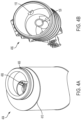
- FIG. 4A a perspective view of a filter element 404 that includes an eccentrically (e.g., not sharing a common center) oriented dual lip seal member 402 on an endplate 410, according to another example embodiment.
- the eccentric filter element 404 is substantially similar to the concentric filter element 104 of FIGS. 1-3 . Accordingly, the eccentric filter element 404 provides substantially the same benefits and features as the concentric filter element 104.
- the filter element 404 further includes a protruding member 408 to facilitate installation into the complementary housing 406.
- FIG. 4B shows a perspective view of a housing 406 that is complementary to the filter element of FIG. 4A , according to an example embodiment.
- Coupled means the joining of two members directly or indirectly to one another. Such joining may be stationary (e.g., permanent) or moveable (e.g., removable or releasable). Such joining may be achieved with the two members or the two members and any additional intermediate members being integrally formed as a single unitary body with one another or with the two members or the two members and any additional intermediate members being attached to one another.
Landscapes
- Chemical & Material Sciences (AREA)
- Chemical Kinetics & Catalysis (AREA)
- Lubrication Details And Ventilation Of Internal Combustion Engines (AREA)
- Filtration Of Liquid (AREA)
- Farming Of Fish And Shellfish (AREA)
Abstract
Description
- The present application claims priority to
Indian Provisional Patent Application No. 201741037236, filed October 21, 2017 - The present application relates to filtration systems. More particularly, the present application relates to fluid filtration systems having a replaceable filter element.
- Fluid filtration systems are used to provide clean fluid to a device. For example, internal combustion engines may have multiple filtration systems to provide clean fuel, clean oil, and clean fluid (e.g., liquid, air, hydraulic, etc.) to the various components of the internal combustion engines. Each filtration system generally includes a filter element having a filter media that filters the fluid. Some filtration systems, such as fuel and oil filtration systems, often use replaceable filter elements that require periodic filter element replacement services to ensure proper filtration of the fluids. In some filtration systems, the filter element can remain immersed in the fluid to be filtered even when not in use. For example, after operation of an internal combustion engine has ceased, residual fuel to be filtered by a fuel filter element may remain in the filter element housing. In such situations, the residual fuel may spill from the filtration system during removal of the housing (e.g., removal of a housing that contains the filter element) or removal of the filter element from the housing during a service operation to change the filter element.
- Filter elements (e.g., filter cartridges) often include a seal member that is compressed against a component of the filtration system housing or another portion of the filtration system. The seal member forms a seal between the filtration system housing and the filter element, thereby preventing fluid from bypassing the filter elements (e.g., for air to bypass an air filter element or liquid to bypass a liquid filter element). If an improper filter element (i.e., a non-authorized or non-genuine filter element) is installed in a filtration system, or if the proper filter element is installed incorrectly, the seal member of the filter element may not form a proper seal, and fluid may bypass the filter element, causing damage to downstream components or a drop in operating pressure. Accordingly, the installation of an improper filter element can harm critical components in the filtration system, cause improper sealing, diminish emission compliance mechanisms, cause subpar performance, and the like.
- One example embodiment relates to a filtration system. The filtration system includes a housing having a drain. A filter element is positioned within the housing. The filter element includes a first endplate and a second endplate. Filter media is positioned between the first endplate and second endplate. A dual lip seal member is coupled to the second endplate. The dual lip seal member comprises a first protrusion that extends radially outward around an outer surface of the dual lip seal member. A second protrusion extends radially outward around the outer surface of the dual lip seal member. The dual lip seal member is configured to prevent fluid to be filtered from exiting the housing through the drain when the filter element is in an installed position. The dual lip seal member permits residual fluid to exit the housing through the drain when the filter element is displaced from the installed position.
- Another example embodiment relates to a filter element. The filter element includes a first endplate and a second endplate. Filter media is positioned between the first endplate and second endplate. A dual lip seal member is coupled to the second endplate. The dual lip seal member comprises a first protrusion that extends radially outward around an outer surface of the dual lip seal member. A second protrusion extends radially outward around the outer surface of the dual lip seal member. The dual lip seal member is configured to prevent fluid to be filtered from exiting through a drain when the filter element is in an installed position in a housing. The dual lip seal member permits residual fluid to exit through the drain when the filter element is displaced from the installed position.
- These and other features, together with the organization and manner of operation thereof, will become apparent from the following detailed description when taken in conjunction with the accompanying drawings, wherein like elements have like numerals throughout the several drawings described below.
-
-
FIG. 1 shows a cross-sectional view of a filtration system that includes a filter element with a dual lip seal member, according to an example embodiment. -
FIG. 2 shows a cross-sectional view of the dual lip seal member of the filtration system ofFIG. 1 . -
FIG. 3 shows an exploded cross-sectional view of the dual lip seal member ofFIG. 1 . -
FIG. 4A shows a perspective view of a filter element that includes an eccentrically oriented dual lip seal member, according to another example embodiment. -
FIG. 4B shows a perspective view of a housing that is complementary to the filter element ofFIG. 4A , according to an example embodiment. - Referring to the figures generally, various embodiments disclosed herein relate to a filtration system with a filter element that includes a dual lip seal (e.g., a dual lip seal member) that functions as an anti-drain seal. The dual lip seal member prevents fluid (e.g., fuel) being filtered from flowing back to a fluid storage tank (e.g., a fuel tank) through a drain in the filter housing when the filter element is in an installed position within the filter housing. Stated differently, the dual lip seal member prevents the dirty (e.g., yet to be filtered) fluid traveling through the inlet from flowing into the fluid storage tank. Further, the configuration of the dual lip seal member with the filter housing allows fluid to flow back to the fluid storage tank when the filter element is being removed from the filter housing (e.g., during a filter change service). Additionally, the dual lip seal member prevents fuel on the dirty side (e.g., inlet) of the filter element from entering a water sump of the filtration system, thereby eliminating the need for a separate seal member. Non-compatible filter elements without the dual lip seal member will permit fluid to return to the fluid tank when the non-compatible filter element is installed in the filtration system. Since the fuel returns to the tank when the engine is off, the lack of fuel will cause a hard engine start when the engine is being restarted. Accordingly, the dual lip seal member also functions as an engine integrity protection mechanism, helping to ensure that an installed filter element is genuine (i.e., authorized, Original Equipment Manufacturer ("OEM") approved, etc.). Thus, the dual lip seal member performs multiple functions (anti-drain back to tank functions, draining functions, and engine integrity protection functions), thereby reducing the cost over traditional filter elements that require three separate components for each of the functions.
- Referring to
FIG. 1 , a cross-sectional view of afiltration system 100 that includes afilter element 104 with a duallip seal member 102 is shown, according to an example embodiment. The filtration system includes afilter element 104, acomplementary housing 106, and afilter mounting head 103. Thefilter element 104 is installed in an interior compartment of ahousing 106 in an installed position (i.e., in an operational position that permits filtering of the fluid). In the installed or operational position, thefilter element 104 is connected to a filter mounting head (e.g., as described above) and thehousing 106 is also attached to the filter mounting head 103 (e.g., via a threaded connection in arrangements where thehousing 106 is a spin-on housing). Thefilter element 104 includes a duallip seal member 102 that forms a radial seal between thefiltration system housing 106 and thefilter element 104, thereby preventing fluid from bypassing thefilter element 104. Generally, when thefilter element 104 is received in the installed position within the housing 106 (i.e., thefiltration system 100 is assembled), the duallip seal member 102 forms a seal between thehousing 106 and thefilter element 104. The duallip seal member 102 prevents the fluid from exiting thehousing 106 through thedrain passage 118. As will be appreciated, if an improper filter element (i.e., a non-authorized or non-genuine filter element) is installed in afiltration system 100, or if the proper filter element is installed incorrectly, the duallip seal member 102 of thefilter element 104 may not form a proper seal, and fluid may bypass thefilter element 104 causing damage to downstream components or improper operation of thefiltration system 100 or other components. - The
filter element 104 includes afirst endplate 108, asecond endplate 110,filter media 112, and the duallip seal member 102. Thefilter element 104 may be a cylindrical filter element with similarly shaped components. Thefilter media 112 includes an inner clean (e.g., filtered fuel)side 116 and an outer dirty (e.g. unfiltered fuel)side 114. Accordingly, thefilter element 104 is an outside-in flow filter element. In an alternative arrangement, thefilter element 104 is an inside-out flow filter element having an innerdirty side 114 and an outerclean side 116. Fluid to be filtered passes from thedirty side 114 of thefilter media 112 to the clean side of thefilter media 112. Thefilter media 112 may include any of paper-based filter media, fiber-based filter media, foam-based filter media, or the like. Thefilter media 112 is disposed between thefirst endplate 108 and thesecond endplate 110. - As shown in
FIG. 1 , thefirst endplate 108 is coupled to a first, top end of thefilter media 112. Thefirst endplate 108 may include a plurality of retention tabs to secure thefilter element 104 to a filter mounting head of thefiltration system 100 when thefilter element 104 is installed in thefiltration system 100. For example, the retention tabs may form a snap-fit connection with thefilter mounting head 103 of thefiltration system 100 as thefilter element 104 is installed in thefiltration system 100. The retention tabs removably secure thefilter element 104 to the mounting head during removal of thehousing 106 of thefiltration system 100, thereby permitting residual fluid in the housing to drain past the duallip seal member 102 back into a fluid storage tank. - The
filter element 104 further includes asecond endplate 110 coupled to a second, bottom end of thefilter media 112. In some embodiments, thesecond endplate 110 includes a central opening. The central opening is sized and shaped to receive a component of a filtration system (e.g., a standpipe) when thefilter element 104 is installed in an operating position within the filtration system. In other embodiments, the central opening is in fluid communication with a water sump. Thefirst endplate 108 may also include a central opening. The central opening may route fluid and air to a component (e.g., to an internal combustion engine). The central opening may be configured to be in fluid communication with acenter housing portion 126 of thehousing 106. - The
filter element 104 includes a duallip seal member 102. The duallip seal member 102 is configured as an anti-drain dual lip seal member. The duallip seal member 102 includes acentral opening 120, afirst protrusion 122, and asecond protrusion 124. The duallip seal member 102 comprises a cylindrical seal member with thefirst protrusion 122 andsecond protrusion 124 being disposed around the outer surface of theseal member 102. The duallip seal member 102 is disposed adjacent to thedrain passage 118 in thehousing 106 that is in fluid communication with the fluid storage tank (not shown). The dual seal member may be formed concentrically (e.g., having a common center) with thefiltration system 100 or eccentrically (e.g., not having a common center) with the filtration system 100 (as shown below inFIGS. 4A-4B ). The duallip seal member 102 is coupled to thesecond endplate 110. In some embodiments, the duallip seal member 102 is disposed around an outer surface of thesecond endplate 110, the outer surface extending axially away from a bottom surface of thesecond endplate 110 away from thefirst endplate 108. In some embodiments, the duallip seal member 102 and thesecond endplate 110 may be manufactured as a single, integrated piece (e.g., via an over molding or heat staking process). In other embodiments, thesecond endplate 110 includes a retaining member, such that a snap-fit connection is formed between the retaining member andcentral opening 120 of the duallip seal member 102. The snap-fit connection removably secures the duallip seal member 102 to thesecond endplate 110. Thecentral opening 120 of the duallip seal member 102 is aligned with a central opening that is configured to allow a component (e.g., the standpipe) to be received through thecentral opening 120 of the duallip seal member 102. - The
first protrusion 122 and thesecond protrusion 124 provide a radial seal with both the top and bottom side of thesecond endplate 110. Beneficially in a particular embodiment, the duallip seal member 102 includes two different lip seal diameters, as thefirst protrusion 122 has a first diameter and thesecond protrusion 124 has a second diameter. Accordingly, the diameters of thefirst protrusion 122 and thesecond protrusion 124 may be adjusted to provide ease of installation of thefilter element 104 into thehousing 106. This ensures that the assembly of thefilter element 104 andhousing 106 is successful only when thefilter element 104 andhousing 106 are properly aligned (e.g., sealed). In some embodiments, the first diameter and the second diameter may be substantially similar. In other embodiments, the first diameter and the second diameter are different diameters. - As shown in
FIG. 1 and2 , the duallip seal member 102 includes afirst protrusion 122 and asecond protrusion 124 comprising a generally sideways 'v'-shape, with thecenter 130 of the dual lip seal (e.g., the indention of the tip of the 'v' shape) being adjacent to thedrain passage 118. Thefirst protrusion 122 and thesecond protrusion 124 extend around the outer surface around the duallip seal member 102. In some embodiments, thefirst protrusion 122 extends at a substantially 45-degree angle above a horizontal axis and the second protrusion extends at a substantially 45-degree angle below the horizontal axis, where the horizontal axis is parallel to the horizontal surface of thesecond endplate 110. While the duallip seal member 102 is shown having two protrusions in a generally sideways 'v'-shape, a wide variety of configurations may be implemented including variations in the shape of the duallip seal member 102, size of duallip seal member 102, and number of protrusions of the duallip seal member 102. The duallip seal member 102 is configured to have a shape, length, width, and number of elements that is specifically tailored to interface with an inner surface of thehousing 106. For example, the duallip seal member 102 may comprise two separate O-rings, multiple lips, or other various shapes and configurations involving one or more lips and O-rings. This ensures that the assembly of thefilter element 104 andhousing 106 is successful only when thefilter element 104 andhousing 106 are properly aligned (e.g., sealed) and ensure engine integrity (e.g., genuine filter element 104). - Referring to
FIG. 2 , a cross-sectional view of the duallip seal member 102 of thefiltration system 100 ofFIG. 1 is shown.FIG. 2 shows the area of thefilter element 104 near thesecond endplate 110. Thefirst protrusion 122 of the duallip seal member 102 presses against afirst portion 202 of an inner surface of thehousing 106 and thesecond protrusion 124 of the duallip seal member 102 presses against a lower,second portion 204 of the inner surface of thehousing 106. Thedrain passage 118 is located between thefirst protrusion 122 and thesecond protrusion 124 and adjacent the base formed by thefirst protrusion 122 andsecond protrusion 124. Thus, thefirst protrusion 122 and thesecond protrusion 124 create a one-way valve, allowing the fluid to enter thehousing 106 and preventing the fluid from returning back to the fluid storage tank. Accordingly, the duallip seal member 102 prevents fluid to be filtered from exiting through adrain passage 118 located in thehousing 106 while thefilter element 104 is received in the installed position within thehousing 106. In such arrangements, thedrain passage 118 connects thehousing 106 to a fluid storage tank (e.g., the fuel tank of a vehicle powered by the internal combustion engine). Accordingly, the duallip seal member 102 functions as an anti-drain back to the storage tank when thefilter element 104 is installed in the housing 106 (e.g., between filter service operations). -
FIG. 3 shows a close-up cross-sectional view of the duallip seal member 102 interacting with thehousing 106 when thefilter element 104 is received in the installed position within thehousing 106. As shown inFIG. 3 , the dual lip seal member includes thefirst protrusion 122 and thesecond protrusion 124. Thefirst protrusion 122 and thesecond protrusion 124 may include flexing features or flanges to provide sealing between thehousing 106 and thefilter element 104. The flexing features allow the first and/or second protrusions (122,124) of the duallip seal member 102 to flex with respect to the main body of the duallip seal member 102. Accordingly, the flexing features can assist in creating the dual lip seal member between thefirst protrusion 122 and thehousing 106 and thesecond protrusion 124 and thehousing 106. The flexing features may comprise grooves or cuts in the duallip seal member 102 positioned at the joint between each of thefirst protrusion 122 and thesecond protrusion 124 and the main body of the duallip seal member 102. The flexing features also permit the duallip seal member 102 to flex during full fluid flow, which reduces restriction and potential damage to the dual lip seal member 102 (e.g., reduces the risk of permanent deformation of the dual lip seal member 102). In some embodiments, one or both of thefirst protrusion 122 and thesecond protrusion 124 include afirst node 302 and a second node 304 (generally in the location shown inFIG. 3 ). The inclusion of thefirst node 302 and the second node 304 on either one of thefirst protrusion 122 andsecond protrusion 124 creates a tighter seal between the duallip seal member 102 and the inner surfaces (202,204) of thehousing 106. - Accordingly, when the
filter element 104 is received in the installed position within the filtration system (i.e., within thehousing 106 when both thehousing 106 and thefilter element 104 are secured to the filter mounting head 103), the duallip seal member 102 forms a radially directed seal between thehousing 106 and thefirst protrusion 122 and thesecond protrusion 124 and thehousing 106. The duallip seal member 102 prevents the fluid from exiting thehousing 106 through thedrain passage 118. During servicing of the filter element 104 (e.g., during filter element replacement) by a technician, the technician first removes thehousing 106 from thefilter mounting head 103. In doing so, thehousing 106 is displaced relative to thefilter element 104. - As mentioned above, the dual
lip seal member 102 provides clean servicing (e.g., when the dirty fuel is drained to the tank). By way of example, thehousing 106 is removed (e.g., spun off) from a filter mounting head and thefilter element 104 remains attached to thefilter mounting head 103 through the retention tabs (e.g., as discussed above with respect toFIG. 1 ). Accordingly, thehousing 106 slides with respect to the duallip seal member 102. Thehousing 106 includes a variable inner diameter. When thefilter element 104 is in the installed position, thefirst protrusion 122 and thesecond protrusion 124 of the duallip seal member 102 form a dual lip seal against afirst portion 202 andsecond portion 204, respectively, of thehousing 106. When thehousing 106 is displaced from thefilter element 104 during removal of the housing 106 (e.g., during a filter replacement service), thefirst protrusion 122 and thesecond protrusion 124 slide to a third and fourth portion of the housing. The third and fourth portions have a larger diameter than thefirst portion 202 andsecond portion 204. The third and fourth portions may include vertical ribs that displace thefirst protrusion 122 and thesecond protrusion 124 from the surface of the third and fourth portions thereby eliminating the dual seal between the duallip seal member 102 and thehousing 106. The vertical ribs prevent thefirst protrusion 122 and thesecond protrusion 124 from being pressed against the surface of the third and fourth portions by the weight of the residual fluid. As will be appreciated, because there is no duallip seal member 102, fluid within thehousing 106 can bypass the duallip seal member 102 for draining out of thehousing 106 through thedrain passage 118. Accordingly, thefilter element 104 can be serviced without spilling or wasting residual fluid in thehousing 106. - Referring to
FIG. 4A , a perspective view of afilter element 404 that includes an eccentrically (e.g., not sharing a common center) oriented dual lip seal member 402 on anendplate 410, according to another example embodiment. As will be appreciated, theeccentric filter element 404 is substantially similar to theconcentric filter element 104 ofFIGS. 1-3 . Accordingly, theeccentric filter element 404 provides substantially the same benefits and features as theconcentric filter element 104. As shown inFIG. 4A , thefilter element 404 further includes a protrudingmember 408 to facilitate installation into thecomplementary housing 406.FIG. 4B shows a perspective view of ahousing 406 that is complementary to the filter element ofFIG. 4A , according to an example embodiment. - It should be noted that any use of the term "exemplary" herein to describe various embodiments is intended to indicate that such embodiments are possible examples, representations, and/or illustrations of possible embodiments (and such term is not intended to connote that such embodiments are necessarily extraordinary or superlative examples).
- The terms "coupled," "connected," and the like as used herein mean the joining of two members directly or indirectly to one another. Such joining may be stationary (e.g., permanent) or moveable (e.g., removable or releasable). Such joining may be achieved with the two members or the two members and any additional intermediate members being integrally formed as a single unitary body with one another or with the two members or the two members and any additional intermediate members being attached to one another.
- References herein to the positions of elements (e.g., "top," "bottom," "above," "below," etc.) are merely used to describe the orientation of various elements in the FIGURES. It should be noted that the orientation of various elements may differ according to other exemplary embodiments, and that such variations are intended to be encompassed by the present disclosure.
- It is important to note that the construction and arrangement of the various exemplary embodiments are illustrative only. Although only a few embodiments have been described in detail in this disclosure, those skilled in the art who review this disclosure will readily appreciate that many modifications are possible (e.g., variations in sizes, dimensions, structures, shapes and proportions of the various elements, values of parameters, mounting arrangements, use of materials, colors, orientations, etc.) without materially departing from the novel teachings and advantages of the subject matter described herein. For example, elements shown as integrally formed may be constructed of multiple parts or elements, the position of elements may be reversed or otherwise varied, and the nature or number of discrete elements or positions may be altered or varied. The order or sequence of any process or method steps may be varied or resequenced according to alternative embodiments. Additionally, features from particular embodiments may be combined with features from other embodiments as would be understood by one of ordinary skill in the art. Other substitutions, modifications, changes and omissions may also be made in the design, operating conditions and arrangement of the various exemplary embodiments without departing from the scope of the present invention.
- Embodiments of the present invention may also be described by one or more of the following numbered clauses:
- 1. A filtration system comprising:
- a housing including a drain; and
- a filter element positioned within the housing, the filter element comprising:
- a first endplate;
- a second endplate;
- filter media positioned between the first endplate and the second endplate; and
- a dual lip seal member coupled to the second endplate, the dual lip seal member comprising a first protrusion that extends radially outward around an outer surface of the dual lip seal member and a second protrusion that extends radially outward around the outer surface of the dual lip seal member, the dual lip seal member configured to prevent fluid to be filtered from exiting the housing through the drain when the filter element is in an installed position within the housing and to permit residual fluid to exit the housing through the drain when the filter element is displaced from the installed position.
- 2. The filtration system of clause 1, wherein the dual lip seal member further comprises a center portion disposed between the first protrusion and the second protrusion, wherein the first protrusion extends at a substantially 45-degree angle above a horizontal axis and the second protrusion extends at a substantially 45-degree angle below the horizontal axis, the horizontal axis parallel second endplate.
- 3. The filtration system of clause 1, wherein contact of the first protrusion and a first housing surface of the housing when in the installed position forms a first radial seal, wherein contact of the second protrusion and a second housing surface of the housing when in the installed position forms a second radial seal, the first housing surface disposed above the drain and the second housing surface disposed below the drain.
- 4. The filtration system of clause 3, wherein the first radial seal is configured to prevent fluid to be filtered from exiting the housing through the drain when the filter element is in an installed position within the housing and the second radial seal is configured to permit residual fluid to exit the housing through the drain when the filter element is displaced from the installed position.
- 5. The filtration system of clause 1, wherein the first protrusion has a first end and a second end, the first end in contact with the outer surface of the dual lip seal member, the second end comprising a first node and a second node, the first node and the second node configured to form a radial seal with an inner surface of the housing.
- 6. The filtration system of clause 1, wherein the first protrusion has a first outer diameter and the second protrusion has a second outer diameter, the first outer diameter being larger than the second outer diameter.
- 7. The filtration system of clause 1, wherein the dual lip seal member is removably coupled to the second endplate.
- 8. The filtration system of clause 7, wherein the dual lip seal member is removably coupled to the second endplate via a snap-fit connection.
- 9. The filtration system of clause 1, wherein the dual lip seal member is overmolded to the second endplate.
- 10. The filtration system of clause 1, wherein the second endplate further comprises an outer endplate surface extending axially from the second endplate away from the first endplate, the outer endplate surface comprising a cylindrical shape, wherein the dual lip seal member is removably coupled to the outer endplate surface.
- 11. The filtration system of clause 1, wherein when the filter element is in the installed position, the dual lip seal member forms a radial seal with the housing, and when the filter element is displaced from the installed position with respect to the housing, the dual lip seal member is prevented from forming a radial seal against housing by a vertical rib.
- 12. The filtration system of clause 1, wherein the first protrusion of the dual lip seal member comprises at least one flexing feature configured to allow the first protrusion of the dual lip seal member to flex.
- 13. The filtration system of clause 1, wherein the dual lip seal member further comprises a center portion disposed between the first protrusion and the second protrusion, the center portion being adjacent to the drain.
- 14. A filter element comprising:
- a first endplate;
- a second endplate;
- filter media positioned between the first endplate and the second endplate; and
- a dual lip seal member coupled to the second endplate, the dual lip seal member comprising a first protrusion that extends radially outward around an outer surface of the dual lip seal member and a second protrusion that extends radially outward around the outer surface of the dual lip seal member, the dual lip seal member configured to prevent fluid to be filtered from exiting through a drain when the filter element is in an installed position within a housing and to permit residual fluid to exit through the drain when the filter element is displaced from the installed position.
- 15. The filter element of clause 14, wherein the dual lip seal member further comprises a center portion disposed between the first protrusion and the second protrusion, wherein the first protrusion extends at a substantially 45-degree angle above a horizontal axis and the second protrusion extends at a substantially 45-degree angle below the horizontal axis, the horizontal axis parallel second endplate.
- 16. The filter element of clause 14, wherein the second endplate further comprises an outer endplate surface extending axially from the second endplate away from the first endplate, the outer endplate surface comprising a cylindrical shape, wherein the dual lip seal member is removably coupled to the outer endplate surface.
- 17. The filter element of clause 14, wherein contact of the first protrusion and a first housing surface of the housing when in the installed position forms a first radial seal, wherein contact of the second protrusion and a second housing surface of the housing when in the installed position forms a second radial seal, the first housing surface disposed above the drain and the second housing surface disposed below the drain.
- 18. The filter element of clause 17, wherein the first radial seal is configured to prevent fluid to be filtered from exiting the housing through the drain when the filter element is in an installed position within the housing and the second radial seal is configured to permit residual fluid to exit the housing through the drain when the filter element is displaced from the installed position.
- 19. The filter element of clause 14, wherein the first protrusion of the dual lip seal member comprises at least one flexing feature configured to allow the first protrusion of the dual lip seal member to flex.
- 20. The filter element of clause 14, wherein the dual lip seal member further comprises a center portion disposed between the first protrusion and the second protrusion, the center portion being adjacent to the drain.
Claims (15)
- A filter element (104, 404) comprising:a first endplate (108);a second endplate (110, 410) (110, 410);filter media (112) positioned between the first endplate (108) and the second endplate (110, 410); anda dual lip seal member (102, 402) coupled to the second endplate (110, 410), the dual lip seal member (102, 402) comprising a first protrusion (122) that extends radially outward around an outer surface of the dual lip seal member (102, 402), a second protrusion (124) that extends radially outward around the outer surface of the dual lip seal member (102, 402), and a center portion disposed between the first protrusion (122) and the second protrusion (124), the dual lip seal member (102, 402) configured to prevent fluid from exiting through a drain (118) when the filter element (104, 404) is in an installed position within a housing (106, 406) and to permit residual fluid to exit through the drain (118) when the filter element (104, 404) is displaced from the installed position.
- The filter element (104, 404) of claim 1, wherein the dual lip seal member (102, 402) is disposed entirely on an outer radially-facing surface of the second endplate (110, 410).
- The filter element (104, 404) of claim 1 or claim 2, wherein the first protrusion (122) extends at a substantially 45-degree angle above a horizontal axis and the second protrusion (124) extends at a substantially 45-degree angle below the horizontal axis, the horizontal axis parallel to the second endplate (110, 410).
- The filter element (104, 404) of claim 1 or claim 3, wherein the second endplate (110, 410) further comprises an outer endplate surface extending axially from the second endplate (110, 410) away from the first endplate (108), the outer endplate surface comprising a cylindrical shape, wherein the dual lip seal member (102, 402) is removably coupled to the outer endplate surface.
- The filter element (104, 404) of any preceding claim, wherein contact of the first protrusion (122) and a first housing surface of the housing (106, 406), when in the installed position, forms a first radial seal, and wherein contact of the second protrusion (124) and a second housing surface of the housing (106, 406), when in the installed position, forms a second radial seal, the first housing surface disposed above the drain (118) and the second housing surface disposed below the drain (118).
- The filter element (104, 404) of claim 5, wherein the first radial seal is configured to prevent fluid to be filtered from exiting the housing (106, 406) through the drain (118) when the filter element (104, 404) is in the installed position within the housing (106, 406) and the second radial seal is configured to permit residual fluid to exit the housing (106, 406) through the drain (118) when the filter element (104, 404) is displaced from the installed position.
- The filter element (104, 404) of any preceding claim, wherein the first protrusion (122) of the dual lip seal member (102, 402) comprises at least one flexing feature configured to allow the first protrusion (122) of the dual lip seal member (102, 402) to flex.
- The filter element (104, 404) of claim 7, wherein the at least one flexing feature comprises a groove or cut in the dual lip seal member (102, 402) positioned at a joint between the first protrusion (122) and the center portion.
- The filter element (104, 404) of any preceding claim, wherein the center portion faces radially away from a central axis of the second endplate (110, 410) so that the center portion faces toward the drain (118) when installed in the housing (106, 406).
- The filter element (104, 404) of any preceding claim, wherein the dual lip seal member (102, 402) is arranged eccentrically with the second endplate (110, 410).
- The filter element (104, 404) of any preceding claim, wherein the first protrusion (122) has a first outer diameter and the second protrusion (124) has a second outer diameter, the first outer diameter being different than the second outer diameter.
- The filter element (104, 404) of any preceding claim, wherein the center portion is configured to be positioned adjacent to the drain (118) when installed in the housing (106, 406).
- The filter element (104, 404) of any preceding claim, wherein the first protrusion (122) comprises a first node (302) and a second node (304), the first node (302) and the second node (304) configured to form a seal with an inner surface (202, 402) of the housing (106, 406).
- The filter element (104, 404) of any preceding claim, wherein the dual lip seal member (102, 402) is removably coupled to the second endplate (110, 410) via a snap-fit connection.
- The filter element (104, 404) of any preceding claim, wherein the dual lip seal member (102, 402) is overmolded to the second endplate (110, 410).
Applications Claiming Priority (3)
| Application Number | Priority Date | Filing Date | Title |
|---|---|---|---|
| IN201741037236 | 2017-10-21 | ||
| PCT/US2018/056235 WO2019079412A2 (en) | 2017-10-21 | 2018-10-17 | Filtration system with dual lip seal |
| EP18868618.2A EP3700651B1 (en) | 2017-10-21 | 2018-10-17 | Filtration system with dual lip seal |
Related Parent Applications (2)
| Application Number | Title | Priority Date | Filing Date |
|---|---|---|---|
| EP18868618.2A Division-Into EP3700651B1 (en) | 2017-10-21 | 2018-10-17 | Filtration system with dual lip seal |
| EP18868618.2A Division EP3700651B1 (en) | 2017-10-21 | 2018-10-17 | Filtration system with dual lip seal |
Publications (3)
| Publication Number | Publication Date |
|---|---|
| EP4176954A1 true EP4176954A1 (en) | 2023-05-10 |
| EP4176954C0 EP4176954C0 (en) | 2025-01-22 |
| EP4176954B1 EP4176954B1 (en) | 2025-01-22 |
Family
ID=66174648
Family Applications (2)
| Application Number | Title | Priority Date | Filing Date |
|---|---|---|---|
| EP18868618.2A Active EP3700651B1 (en) | 2017-10-21 | 2018-10-17 | Filtration system with dual lip seal |
| EP22210306.1A Active EP4176954B1 (en) | 2017-10-21 | 2018-10-17 | Filter element with dual lip seal |
Family Applications Before (1)
| Application Number | Title | Priority Date | Filing Date |
|---|---|---|---|
| EP18868618.2A Active EP3700651B1 (en) | 2017-10-21 | 2018-10-17 | Filtration system with dual lip seal |
Country Status (4)
| Country | Link |
|---|---|
| US (2) | US11673077B2 (en) |
| EP (2) | EP3700651B1 (en) |
| CN (1) | CN111278527A (en) |
| WO (1) | WO2019079412A2 (en) |
Families Citing this family (1)
| Publication number | Priority date | Publication date | Assignee | Title |
|---|---|---|---|---|
| US11673077B2 (en) * | 2017-10-21 | 2023-06-13 | Cummins Filtration Ip, Inc. | Filtration system with dual lip seal |
Citations (4)
| Publication number | Priority date | Publication date | Assignee | Title |
|---|---|---|---|---|
| US6543625B1 (en) * | 1998-11-16 | 2003-04-08 | Fleetguard, Inc. | Cartridge for filtering a liquid circulating in a hydraulic engine or equipment and corresponding filtering cartridge-sealing joint assembly |
| US20080035587A1 (en) * | 2006-08-08 | 2008-02-14 | Wieczorek Mark T | Quick-drain filter |
| US20110084016A1 (en) * | 2008-03-21 | 2011-04-14 | Cummins Filtration | Filtration assembly including a central tube interacting with a filtration cartridge and with a seal permanently mounted on said central tube |
| US20140230389A1 (en) * | 2009-08-11 | 2014-08-21 | Mann+Hummel Gmbh | Sealing Device of a Filter System for Filtering Fluids |
Family Cites Families (5)
| Publication number | Priority date | Publication date | Assignee | Title |
|---|---|---|---|---|
| ITRE20050089A1 (en) * | 2005-07-22 | 2007-01-23 | Ufi Filters Spa | FILTERING DEVICE FOR OIL FILTRATION |
| JP4873486B2 (en) * | 2007-05-21 | 2012-02-08 | Necソフト株式会社 | Method for predicting secondary structure of nucleic acid sequence, apparatus for predicting secondary structure of nucleic acid sequence, and program for predicting secondary structure of nucleic acid sequence |
| US20090294351A1 (en) | 2008-05-28 | 2009-12-03 | Herman Peter K | Filter seal |
| FR3036040A1 (en) * | 2015-05-11 | 2016-11-18 | Cummins Filtration Ip Inc | FILTRATION SYSTEM COMPRISING AN ANTI-RETURN VALVE AND AN X DRAIN SEAL |
| US11673077B2 (en) * | 2017-10-21 | 2023-06-13 | Cummins Filtration Ip, Inc. | Filtration system with dual lip seal |
-
2018
- 2018-10-17 US US16/755,957 patent/US11673077B2/en active Active
- 2018-10-17 WO PCT/US2018/056235 patent/WO2019079412A2/en not_active Ceased
- 2018-10-17 CN CN201880066502.0A patent/CN111278527A/en active Pending
- 2018-10-17 EP EP18868618.2A patent/EP3700651B1/en active Active
- 2018-10-17 EP EP22210306.1A patent/EP4176954B1/en active Active
-
2023
- 2023-04-27 US US18/140,230 patent/US12186686B2/en active Active
Patent Citations (4)
| Publication number | Priority date | Publication date | Assignee | Title |
|---|---|---|---|---|
| US6543625B1 (en) * | 1998-11-16 | 2003-04-08 | Fleetguard, Inc. | Cartridge for filtering a liquid circulating in a hydraulic engine or equipment and corresponding filtering cartridge-sealing joint assembly |
| US20080035587A1 (en) * | 2006-08-08 | 2008-02-14 | Wieczorek Mark T | Quick-drain filter |
| US20110084016A1 (en) * | 2008-03-21 | 2011-04-14 | Cummins Filtration | Filtration assembly including a central tube interacting with a filtration cartridge and with a seal permanently mounted on said central tube |
| US20140230389A1 (en) * | 2009-08-11 | 2014-08-21 | Mann+Hummel Gmbh | Sealing Device of a Filter System for Filtering Fluids |
Also Published As
| Publication number | Publication date |
|---|---|
| US11673077B2 (en) | 2023-06-13 |
| WO2019079412A3 (en) | 2020-04-02 |
| US20230256362A1 (en) | 2023-08-17 |
| EP4176954C0 (en) | 2025-01-22 |
| US20200289963A1 (en) | 2020-09-17 |
| WO2019079412A2 (en) | 2019-04-25 |
| EP3700651B1 (en) | 2023-08-30 |
| CN111278527A (en) | 2020-06-12 |
| US12186686B2 (en) | 2025-01-07 |
| EP3700651A4 (en) | 2021-05-26 |
| EP4176954B1 (en) | 2025-01-22 |
| EP3700651C0 (en) | 2023-08-30 |
| EP3700651A2 (en) | 2020-09-02 |
Similar Documents
| Publication | Publication Date | Title |
|---|---|---|
| US20160332095A1 (en) | Filtration System with Anti Drain Valve and Drain X-Seal | |
| US20140251889A1 (en) | Depth coalescing filter with barrier media patch | |
| US20190111363A1 (en) | A filter insert and a filter arrangement | |
| CN112399879A (en) | Alignment notches for end caps of filter elements | |
| CN106545443B (en) | Filter element and filter assembly for separating fluids | |
| US20210170316A1 (en) | Self-assisting element removal features for a filtration system | |
| US12186686B2 (en) | Filtration system with dual lip seal | |
| CN110248714B (en) | Expandable threaded adapter for threadless housings | |
| WO2015153006A1 (en) | Filter assembly | |
| AU2025203970A1 (en) | Fuel filter passage for downward fuel flow direction | |
| US20250186911A1 (en) | Filter cartridge with offset outlet and integrated bypass | |
| WO2019112560A1 (en) | Filter element with barrier | |
| WO2017053270A1 (en) | System and method for oil filtration in bypass mode | |
| US11826684B2 (en) | Filter interlock with tabs mating with a pedestal or a housing | |
| EP3773972B1 (en) | Chambered parallel flow dual filter | |
| CA3199369C (en) | Fuel filter passage for downward fuel flow direction | |
| US20210077924A1 (en) | Liquid filter positioning and sealing feature | |
| WO2019112563A1 (en) | Integral flow structure within a containment cover |
Legal Events
| Date | Code | Title | Description |
|---|---|---|---|
| PUAI | Public reference made under article 153(3) epc to a published international application that has entered the european phase |
Free format text: ORIGINAL CODE: 0009012 |
|
| STAA | Information on the status of an ep patent application or granted ep patent |
Free format text: STATUS: THE APPLICATION HAS BEEN PUBLISHED |
|
| AC | Divisional application: reference to earlier application |
Ref document number: 3700651 Country of ref document: EP Kind code of ref document: P |
|
| AK | Designated contracting states |
Kind code of ref document: A1 Designated state(s): AL AT BE BG CH CY CZ DE DK EE ES FI FR GB GR HR HU IE IS IT LI LT LU LV MC MK MT NL NO PL PT RO RS SE SI SK SM TR |
|
| P01 | Opt-out of the competence of the unified patent court (upc) registered |
Effective date: 20230605 |
|
| STAA | Information on the status of an ep patent application or granted ep patent |
Free format text: STATUS: REQUEST FOR EXAMINATION WAS MADE |
|
| 17P | Request for examination filed |
Effective date: 20231030 |
|
| RBV | Designated contracting states (corrected) |
Designated state(s): AL AT BE BG CH CY CZ DE DK EE ES FI FR GB GR HR HU IE IS IT LI LT LU LV MC MK MT NL NO PL PT RO RS SE SI SK SM TR |
|
| GRAP | Despatch of communication of intention to grant a patent |
Free format text: ORIGINAL CODE: EPIDOSNIGR1 |
|
| STAA | Information on the status of an ep patent application or granted ep patent |
Free format text: STATUS: GRANT OF PATENT IS INTENDED |
|
| INTG | Intention to grant announced |
Effective date: 20240909 |
|
| GRAS | Grant fee paid |
Free format text: ORIGINAL CODE: EPIDOSNIGR3 |
|
| GRAA | (expected) grant |
Free format text: ORIGINAL CODE: 0009210 |
|
| STAA | Information on the status of an ep patent application or granted ep patent |
Free format text: STATUS: THE PATENT HAS BEEN GRANTED |
|
| AC | Divisional application: reference to earlier application |
Ref document number: 3700651 Country of ref document: EP Kind code of ref document: P |
|
| AK | Designated contracting states |
Kind code of ref document: B1 Designated state(s): AL AT BE BG CH CY CZ DE DK EE ES FI FR GB GR HR HU IE IS IT LI LT LU LV MC MK MT NL NO PL PT RO RS SE SI SK SM TR |
|
| REG | Reference to a national code |
Ref country code: GB Ref legal event code: FG4D |
|
| REG | Reference to a national code |
Ref country code: CH Ref legal event code: EP |
|
| REG | Reference to a national code |
Ref country code: IE Ref legal event code: FG4D |
|
| REG | Reference to a national code |
Ref country code: DE Ref legal event code: R096 Ref document number: 602018078806 Country of ref document: DE |
|
| P04 | Withdrawal of opt-out of the competence of the unified patent court (upc) registered |
Free format text: CASE NUMBER: APP_4755/2025 Effective date: 20250129 |
|
| U01 | Request for unitary effect filed |
Effective date: 20250127 |
|
| U07 | Unitary effect registered |
Designated state(s): AT BE BG DE DK EE FI FR IT LT LU LV MT NL PT RO SE SI Effective date: 20250131 |
|
| PG25 | Lapsed in a contracting state [announced via postgrant information from national office to epo] |
Ref country code: RS Free format text: LAPSE BECAUSE OF FAILURE TO SUBMIT A TRANSLATION OF THE DESCRIPTION OR TO PAY THE FEE WITHIN THE PRESCRIBED TIME-LIMIT Effective date: 20250422 |
|
| PG25 | Lapsed in a contracting state [announced via postgrant information from national office to epo] |
Ref country code: PL Free format text: LAPSE BECAUSE OF FAILURE TO SUBMIT A TRANSLATION OF THE DESCRIPTION OR TO PAY THE FEE WITHIN THE PRESCRIBED TIME-LIMIT Effective date: 20250122 |
|
| PG25 | Lapsed in a contracting state [announced via postgrant information from national office to epo] |
Ref country code: ES Free format text: LAPSE BECAUSE OF FAILURE TO SUBMIT A TRANSLATION OF THE DESCRIPTION OR TO PAY THE FEE WITHIN THE PRESCRIBED TIME-LIMIT Effective date: 20250122 |
|
| PG25 | Lapsed in a contracting state [announced via postgrant information from national office to epo] |
Ref country code: NO Free format text: LAPSE BECAUSE OF FAILURE TO SUBMIT A TRANSLATION OF THE DESCRIPTION OR TO PAY THE FEE WITHIN THE PRESCRIBED TIME-LIMIT Effective date: 20250422 Ref country code: IS Free format text: LAPSE BECAUSE OF FAILURE TO SUBMIT A TRANSLATION OF THE DESCRIPTION OR TO PAY THE FEE WITHIN THE PRESCRIBED TIME-LIMIT Effective date: 20250522 |
|
| PG25 | Lapsed in a contracting state [announced via postgrant information from national office to epo] |
Ref country code: HR Free format text: LAPSE BECAUSE OF FAILURE TO SUBMIT A TRANSLATION OF THE DESCRIPTION OR TO PAY THE FEE WITHIN THE PRESCRIBED TIME-LIMIT Effective date: 20250122 |
|
| PG25 | Lapsed in a contracting state [announced via postgrant information from national office to epo] |
Ref country code: GR Free format text: LAPSE BECAUSE OF FAILURE TO SUBMIT A TRANSLATION OF THE DESCRIPTION OR TO PAY THE FEE WITHIN THE PRESCRIBED TIME-LIMIT Effective date: 20250423 |
|
| PG25 | Lapsed in a contracting state [announced via postgrant information from national office to epo] |
Ref country code: SM Free format text: LAPSE BECAUSE OF FAILURE TO SUBMIT A TRANSLATION OF THE DESCRIPTION OR TO PAY THE FEE WITHIN THE PRESCRIBED TIME-LIMIT Effective date: 20250122 |
|
| PG25 | Lapsed in a contracting state [announced via postgrant information from national office to epo] |
Ref country code: CZ Free format text: LAPSE BECAUSE OF FAILURE TO SUBMIT A TRANSLATION OF THE DESCRIPTION OR TO PAY THE FEE WITHIN THE PRESCRIBED TIME-LIMIT Effective date: 20250122 |
|
| PG25 | Lapsed in a contracting state [announced via postgrant information from national office to epo] |
Ref country code: SK Free format text: LAPSE BECAUSE OF FAILURE TO SUBMIT A TRANSLATION OF THE DESCRIPTION OR TO PAY THE FEE WITHIN THE PRESCRIBED TIME-LIMIT Effective date: 20250122 |
|
| PLBE | No opposition filed within time limit |
Free format text: ORIGINAL CODE: 0009261 |
|
| STAA | Information on the status of an ep patent application or granted ep patent |
Free format text: STATUS: NO OPPOSITION FILED WITHIN TIME LIMIT |
|
| U20 | Renewal fee for the european patent with unitary effect paid |
Year of fee payment: 8 Effective date: 20251027 |
|
| 26N | No opposition filed |
Effective date: 20251023 |
|
| U1H | Name or address of the proprietor changed after the registration of the unitary effect |
Owner name: ATMUS FILTRATION IP, INC.; US |
|
| U1N | Appointed representative for the unitary patent procedure changed after the registration of the unitary effect |
Representative=s name: MARKS & CLERK LLP; GB |