EP4176952A1 - Multi-component mixture separation system - Google Patents
Multi-component mixture separation system Download PDFInfo
- Publication number
- EP4176952A1 EP4176952A1 EP22850567.3A EP22850567A EP4176952A1 EP 4176952 A1 EP4176952 A1 EP 4176952A1 EP 22850567 A EP22850567 A EP 22850567A EP 4176952 A1 EP4176952 A1 EP 4176952A1
- Authority
- EP
- European Patent Office
- Prior art keywords
- section
- distillation column
- stream
- separation system
- component
- Prior art date
- Legal status (The legal status is an assumption and is not a legal conclusion. Google has not performed a legal analysis and makes no representation as to the accuracy of the status listed.)
- Pending
Links
- 239000000203 mixture Substances 0.000 title claims abstract description 47
- 238000000926 separation method Methods 0.000 title claims abstract description 32
- 238000004821 distillation Methods 0.000 claims abstract description 124
- 239000012071 phase Substances 0.000 claims abstract description 60
- 238000009835 boiling Methods 0.000 claims abstract description 58
- 238000005192 partition Methods 0.000 claims abstract description 32
- 239000008346 aqueous phase Substances 0.000 claims abstract description 30
- 238000010992 reflux Methods 0.000 claims abstract description 6
- JJMOMMLADQPZNY-UHFFFAOYSA-N 3-hydroxy-2,2-dimethylpropanal Chemical compound OCC(C)(C)C=O JJMOMMLADQPZNY-UHFFFAOYSA-N 0.000 claims description 43
- AMIMRNSIRUDHCM-UHFFFAOYSA-N Isopropylaldehyde Chemical compound CC(C)C=O AMIMRNSIRUDHCM-UHFFFAOYSA-N 0.000 claims description 25
- 239000007788 liquid Substances 0.000 claims description 20
- 238000000034 method Methods 0.000 description 21
- 238000011084 recovery Methods 0.000 description 14
- 239000006227 byproduct Substances 0.000 description 13
- 230000000052 comparative effect Effects 0.000 description 12
- 238000005265 energy consumption Methods 0.000 description 12
- 241000183024 Populus tremula Species 0.000 description 8
- 238000010438 heat treatment Methods 0.000 description 8
- 238000001816 cooling Methods 0.000 description 6
- 238000010586 diagram Methods 0.000 description 6
- 239000012530 fluid Substances 0.000 description 5
- 239000000126 substance Substances 0.000 description 5
- JCTXKRPTIMZBJT-UHFFFAOYSA-N 2,2,4-trimethylpentane-1,3-diol Chemical compound CC(C)C(O)C(C)(C)CO JCTXKRPTIMZBJT-UHFFFAOYSA-N 0.000 description 4
- 238000005882 aldol condensation reaction Methods 0.000 description 4
- KFZMGEQAYNKOFK-UHFFFAOYSA-N Isopropanol Chemical compound CC(C)O KFZMGEQAYNKOFK-UHFFFAOYSA-N 0.000 description 3
- 230000000694 effects Effects 0.000 description 3
- 239000000047 product Substances 0.000 description 3
- 238000004088 simulation Methods 0.000 description 3
- 238000004891 communication Methods 0.000 description 2
- 238000004519 manufacturing process Methods 0.000 description 2
- 239000011368 organic material Substances 0.000 description 2
- 230000000630 rising effect Effects 0.000 description 2
- SMZOUWXMTYCWNB-UHFFFAOYSA-N 2-(2-methoxy-5-methylphenyl)ethanamine Chemical compound COC1=CC=C(C)C=C1CCN SMZOUWXMTYCWNB-UHFFFAOYSA-N 0.000 description 1
- NIXOWILDQLNWCW-UHFFFAOYSA-N 2-Propenoic acid Natural products OC(=O)C=C NIXOWILDQLNWCW-UHFFFAOYSA-N 0.000 description 1
- WSFSSNUMVMOOMR-UHFFFAOYSA-N Formaldehyde Chemical compound O=C WSFSSNUMVMOOMR-UHFFFAOYSA-N 0.000 description 1
- ISWSIDIOOBJBQZ-UHFFFAOYSA-N Phenol Chemical compound OC1=CC=CC=C1 ISWSIDIOOBJBQZ-UHFFFAOYSA-N 0.000 description 1
- 239000000654 additive Substances 0.000 description 1
- 230000000996 additive effect Effects 0.000 description 1
- 239000003054 catalyst Substances 0.000 description 1
- 238000006243 chemical reaction Methods 0.000 description 1
- 238000009833 condensation Methods 0.000 description 1
- 230000005494 condensation Effects 0.000 description 1
- 238000005516 engineering process Methods 0.000 description 1
- 239000008098 formaldehyde solution Substances 0.000 description 1
- 238000009434 installation Methods 0.000 description 1
- 239000011344 liquid material Substances 0.000 description 1
- 238000012986 modification Methods 0.000 description 1
- 230000004048 modification Effects 0.000 description 1
- 230000000149 penetrating effect Effects 0.000 description 1
- 238000005191 phase separation Methods 0.000 description 1
- 238000006116 polymerization reaction Methods 0.000 description 1
- 239000007787 solid Substances 0.000 description 1
Images


Classifications
-
- B—PERFORMING OPERATIONS; TRANSPORTING
- B01—PHYSICAL OR CHEMICAL PROCESSES OR APPARATUS IN GENERAL
- B01D—SEPARATION
- B01D3/00—Distillation or related exchange processes in which liquids are contacted with gaseous media, e.g. stripping
- B01D3/14—Fractional distillation or use of a fractionation or rectification column
- B01D3/141—Fractional distillation or use of a fractionation or rectification column where at least one distillation column contains at least one dividing wall
-
- B—PERFORMING OPERATIONS; TRANSPORTING
- B01—PHYSICAL OR CHEMICAL PROCESSES OR APPARATUS IN GENERAL
- B01D—SEPARATION
- B01D17/00—Separation of liquids, not provided for elsewhere, e.g. by thermal diffusion
- B01D17/02—Separation of non-miscible liquids
-
- B—PERFORMING OPERATIONS; TRANSPORTING
- B01—PHYSICAL OR CHEMICAL PROCESSES OR APPARATUS IN GENERAL
- B01D—SEPARATION
- B01D17/00—Separation of liquids, not provided for elsewhere, e.g. by thermal diffusion
- B01D17/02—Separation of non-miscible liquids
- B01D17/0208—Separation of non-miscible liquids by sedimentation
- B01D17/0211—Separation of non-miscible liquids by sedimentation with baffles
-
- B—PERFORMING OPERATIONS; TRANSPORTING
- B01—PHYSICAL OR CHEMICAL PROCESSES OR APPARATUS IN GENERAL
- B01D—SEPARATION
- B01D3/00—Distillation or related exchange processes in which liquids are contacted with gaseous media, e.g. stripping
- B01D3/008—Liquid distribution
-
- B—PERFORMING OPERATIONS; TRANSPORTING
- B01—PHYSICAL OR CHEMICAL PROCESSES OR APPARATUS IN GENERAL
- B01D—SEPARATION
- B01D3/00—Distillation or related exchange processes in which liquids are contacted with gaseous media, e.g. stripping
- B01D3/14—Fractional distillation or use of a fractionation or rectification column
- B01D3/143—Fractional distillation or use of a fractionation or rectification column by two or more of a fractionation, separation or rectification step
-
- B—PERFORMING OPERATIONS; TRANSPORTING
- B01—PHYSICAL OR CHEMICAL PROCESSES OR APPARATUS IN GENERAL
- B01D—SEPARATION
- B01D3/00—Distillation or related exchange processes in which liquids are contacted with gaseous media, e.g. stripping
- B01D3/14—Fractional distillation or use of a fractionation or rectification column
- B01D3/32—Other features of fractionating columns ; Constructional details of fractionating columns not provided for in groups B01D3/16 - B01D3/30
-
- B—PERFORMING OPERATIONS; TRANSPORTING
- B01—PHYSICAL OR CHEMICAL PROCESSES OR APPARATUS IN GENERAL
- B01D—SEPARATION
- B01D5/00—Condensation of vapours; Recovering volatile solvents by condensation
- B01D5/0057—Condensation of vapours; Recovering volatile solvents by condensation in combination with other processes
- B01D5/006—Condensation of vapours; Recovering volatile solvents by condensation in combination with other processes with evaporation or distillation
- B01D5/0063—Reflux condensation
-
- C—CHEMISTRY; METALLURGY
- C07—ORGANIC CHEMISTRY
- C07C—ACYCLIC OR CARBOCYCLIC COMPOUNDS
- C07C45/00—Preparation of compounds having >C = O groups bound only to carbon or hydrogen atoms; Preparation of chelates of such compounds
- C07C45/78—Separation; Purification; Stabilisation; Use of additives
- C07C45/81—Separation; Purification; Stabilisation; Use of additives by change in the physical state, e.g. crystallisation
- C07C45/82—Separation; Purification; Stabilisation; Use of additives by change in the physical state, e.g. crystallisation by distillation
Definitions
- the present invention relates to a multi-component mixture separation system, and more particularly, to a multi-component mixture separation system capable of simplifying a process and saving energy in separating a multi-component mixture containing three or more components.
- a process of separating a desired component from other components in a mixture containing three or more components generated through a reaction and recovering unreacted substances may be achieved by a distillation operation sequence.
- This sequence may include a distillation column for separating all of low-boiling point components, medium-boiling point components, and high-boiling point components from the desired mixture.
- two or more distillation columns are required.
- the mixture containing three or more components may be fed to a distillation column of a front stage, the high-boiling point components may be separated into a lower portion in the distillation column of the front stage, the low-boiling point components and the medium-boiling point components may be fed to a distillation column of a rear stage, the low-boiling point components may be separated into an upper portion in the distillation column of the rear stage, and the medium-boiling point components may be separated to a lower portion, respectively.
- the mixture containing three or more components may be fed to the distillation column of the front stage, the low-boiling point components may be separated into an upper portion in the distillation column of the front stage, the medium-boiling point components and the high-boiling point components may be separated to a lower portion, the medium-boiling point and the high-boiling point components may be fed to the distillation column of the rear stage, the medium-boiling point components may be separated into an upper portion in the distillation column of the rear stage, and the high-boiling point components may be separated to a lower portion, respectively.
- two or more distillation columns may be required, and two or more additional devices may also be required, which causes a problem in that the process becomes complicated, and when a stream moves between the two or more distillation columns, unnecessary cooling and heating may be required, which causes a problem in that the number of devices and energy consumption increase.
- the present invention provides a multi-component mixture separation system that uses a distillation column equipped with a partition wall to separate a mixture containing three or more components and control a feed end of a stream refluxed to a mixture containing three or more components to separate the mixture, thereby preventing unnecessary cooling and heating to simplify a process and save energy.
- a multi-component mixture separation system includes a distillation column including a first section and a second section separated by a partition wall, and a phase separator receiving a lower discharge stream of the second section and separating the stream into an aqueous phase and an oil phase, and refluxing a portion of the separated aqueous phase or oil phase to the first section, in which the first section includes a chimney tray provided on an upper portion, and the first section is fed with a feed stream containing three or more components to separate high-boiling point component to a lower portion, and a gaseous component moves to the second section.
- a multi-component mixture separation system uses one distillation column equipped with a partition wall, moves gaseous components from a first section to a second section of the distillation column but prevents liquefied components from moving from the second section to the first section, and controls a feed end of a stream refluxed from a phase separator to the distillation column to separate a mixture, thereby simplifying a process to reduce the number of devices and preventing unnecessary cooling and heating to save energy.
- the load and life-time of a wind turbine are predicted by mounting a strain gauge in the related art, but such a strain gauge is sensitive to electromagnetic noise, so there is a problem in that installation is difficult.
- the present disclosure has been designed to estimate the load and life-time of a wind turbine using a vibration sensor that is relatively easy to install.
- the term 'stream' may mean a flow of a fluid in a process, and may also mean a fluid itself flowing in a pipe. Specifically, the stream may mean both the fluid itself and the flow of the fluid flowing within the pipe connecting each device.
- the fluid may contain any one or more components of a gas, a liquid, and a solid.
- a multi-component mixture separation system includes a distillation column 10 including a first section D1 and a second section D2 separated by a partition wall 11, and a phase separator 20 receiving a lower discharge stream of the second section D2 and separating the stream into an aqueous phase and an oil phase, and refluxing a portion of the separated aqueous phase or oil phase to the first section D1, in which the first section D1 includes a chimney tray 13 provided on an upper portion, and the first section D1 is fed with a feed stream containing three or more components to separate high-boiling point component to a lower portion, and a gaseous component moves to the second section D2.
- a process of separating a desired component from other components in a mixture containing three or more components generated through the existing polymerization reaction and recovering unreacted substances may be achieved by a distillation operation sequence.
- This sequence may include a distillation column for separating all of low-boiling point components, medium-boiling point components, and high-boiling point components from the desired mixture.
- two or more distillation columns are required.
- a mixture containing three or more components may be fed to a distillation column of a front stage, the high-boiling point component may be separated into the lower portion in the distillation column of the front stage, the low-boiling point component and the medium-boiling point component may be fed to a distillation column of a rear stage, the low-boiling point component may be separated into an upper portion in the distillation column of the rear stage, and the medium-boiling point component may be separated to the lower portion, respectively.
- the mixture containing three or more components may be fed to the distillation column of the front stage, the low-boiling point component may be separated into an upper portion in the distillation column of the front stage, the medium-boiling point component and the high-boiling point component may be separated to the lower portion, the medium-boiling point component and the high-boiling point component may be fed to the distillation column of the rear stage, the medium-boiling point component may be separated into an upper portion in the distillation column of the rear stage, and the high-boiling point component may be separated to the lower portion, respectively.
- two or more distillation columns may be required, and two or more additional devices may also be required, which causes a problem in that the process becomes complicated, and when a stream moves between the two or more distillation columns, unnecessary cooling and heating may be required, which causes a problem in that the number of devices and energy consumption increase.
- one distillation column 10 provided with a partition wall 11 is used, and gaseous components move from the first section D1 to the second section D2 of the distillation column 10.
- the present invention provides a multi-component mixture separation system that prevents the liquefied component from moving from the second section D2 to the first section D1 and controls the feed end of the stream refluxed from the phase separator 20 to the distillation column 10 to separate the mixture, thereby reducing the number of devices by simplifying the process and preventing unnecessary cooling and heating to save energy.
- the distillation column 10 may be fed with a feed stream containing three or more components to separate each component.
- the feed stream may contain 3 to 5 components, 3 to 4 components, or 3 components, and as a specific example, the feed stream may contain 3 components.
- the inside of the distillation column 10 may be separated into two sections by the partition wall 11. Specifically, the distillation column 10 may be partitioned into the first section D1 and the second section D2 through a partition wall 11, and the distillation in the first section D1 and the second section D2 may be performed independently.
- the partition wall 11 may be formed to extend upwardly from a lower end of the distillation column 10, for example, and an upper region of the partition wall 11 may communicate.
- the partition wall 11 may extend vertically from the lower end of the distillation column 10 to a height spaced apart from an upper end of the distillation column 10 without reaching the upper end of the distillation column 10, for example. Specifically, the partition wall 11 extends from the lower end of the distillation column 10 to a certain height in an upper direction, that is, in a longitudinal direction of the distillation column 10, and the communication between the first section D1 and the second section D2 in the lower region of the distillation column 10 may be blocked through the partition wall 11 In this case, the height of the partition wall 11 may be, for example, 30% or more, 40% or more, 50% or more and 60% or less, 70% or less, or 80% or less of the height of the distillation column 10.
- the distillation column 10 is partitioned through the partition wall 11, and the first section D1 partitioned through the partition wall 11 may further include a chimney tray 13 provided on the upper portion.
- the chimney tray 13 may be formed to correspond to an upper area of the first section D1 partitioned by the partition wall 11.
- the chimney tray 13 may include a plurality of chimneys communicating the gaseous component rising from the lower region of the chimney tray 13 to the upper region, and prevent the liquefied component that may be accumulated in the chimney tray 13 from penetrating into the lower region of the chimney tray 13.
- the chimney tray 13 may move the gaseous component from the first section D1 to the second section D2 of the distillation column 10, but prevent the liquefied component from moving from the second section D2 to the first section D1
- the communication of the liquefied component may be blocked between the first section D1 and the second section D2 of the distillation column 10 through the chimney tray 13, and the gaseous component may be made to communicate only from the first section D1 to the second section D2 of the distillation column 10. In this way, the gaseous component of the first section D1 of the distillation column 10 moves directly to the second section D2 without a separate condensation and heating step, thereby preventing the use of unnecessary energy to save energy used in the process.
- the partition wall 11 and the chimney tray 13 may be described mainly.
- the first section D1 of the distillation column 10 may mean a section positioned in the lower portion with respect to the chimney tray 13, and as a more specific example, may mean a section partitioned through the partition wall 11 on the side while positioned in the lower portion with respect to the chimney tray 13.
- the second section D2 of the distillation column 10 may mean a section positioned in the upper portion with respect to the chimney tray 13, and as a more specific example, may mean a section partitioned through the partition wall 11 while positioned in the upper portion with respect to the chimney tray 13.
- the first section D1 may further include a liquid distribution device 14 provided under the chimney tray 13.
- the liquid distribution device 14 may serve to evenly spread the liquid material of the upper portion to the lower portion, and may communicate the gaseous component of the lower portion to the upper portion.
- the chimney tray 13 is provided above the first section D1, so that the liquefied component falling from the upper portion to the lower portion of the first section D1 does not exist. Therefore, for the separation of the feed stream in the first section D1, the liquid distribution device 14 is disposed, and the refluxed stream from the phase separator 20 is fed to a position between the chimney tray 13 and the liquid distribution device 14, and thus, liquefied components may be distributed and sprayed to the lower portion of the liquid distribution device 14. In this case, the substance is transferred by bringing the gaseous component boiled in the lower portion of the liquid distribution device 14 into contact with the liquid component sprayed to the lower portion through the liquid distribution device 14, so the separation may effectively occur.
- the feed stream containing three or more components fed to the distillation column 10 may be fed to a position lower than the liquid distribution device 14 provided in the first section D1 of the distillation column 10.
- the feed stream may contain the low-boiling point component, the medium-boiling point component, and the high-boiling point component for each boiling point.
- the feed stream fed to the distillation column 10 is distilled in the first section D1, and the vaporized gaseous component rising through the distillation may pass through the chimney tray 13 to move to the second section D2.
- the liquefied component in the first section D1 of the distillation column 10 may be separated into the lower portion of the distillation column 10, and the lower discharge stream separated into the lower portion in the first section D1 of the distillation column 10 may contain the high-boiling point component of the feed stream.
- the operating condition of the first section D1 is that the high-boiling point component in the feed stream may be separated into the lower portion, and the medium-boiling point component and the low-boiling point component may be vaporized and raised to the upper portion of the first section D1 and may be appropriately adjusted to move to the second section D2.
- the lower discharge stream of the first section D1 is partially refluxed through the conventional reboiler, and the remaining components may be recovered.
- the gaseous component moving to the upper portion of the first section D1 of the distillation column 10 may move to the second section D2 and subjected to additional distillation.
- the gaseous component moving to the second section D2 may contain the medium-boiling point component and the low-boiling point component of the feed stream.
- the medium-boiling point component and the low-boiling point component may be separated through the distillation in the second section D2, and specifically, the low-boiling point component may be separated into the upper portion of the second section D2, and the medium-boiling point component may be separated into the lower portion.
- the upper discharge stream discharged to the upper portion of the second section D2 may contain the low-boiling point component of the feed stream.
- the upper discharge stream of the second section D2 may be condensed in the conventional manner, some of the stream may be refluxed and the remaining stream may be recovered.
- the lower discharge stream separated into the lower portion of the second section D2 of the distillation column 10 is fed to the phase separator 20, and then, the medium-boiling point component may be separated from any one or more of the aqueous phase and the oil phase separated in the phase separator 20.
- some of the lower discharge stream of the second section D2 of the distillation column 10 may be refluxed through the conventional reboiler, and the remaining stream may be fed to the phase separator 20.
- the remaining stream other than the stream refluxed through the reboiler may pass through, for example, a cooler 12, and then, may be fed to the phase separator 20.
- the cooler 12 may cool the stream fed to the phase separator 20.
- the phase separator 20 may be a device for separating an aqueous phase and an oil phase. For example, it is possible to separate the aqueous phase and the oil phase of the lower discharge stream of the second section D2 of the distillation column 10, and reflux some of the separated aqueous phase or oil phase to the first section D1 of the distillation column 10. In this case, some streams of the separated aqueous phase and oil phase may be refluxed to the first section D1 of the distillation column 10, and the medium-boiling point component may be separated from and recovered to streams other than the stream refluxed to the first section D1.
- some of the aqueous phase may be refluxed to the first section D1, and the medium-boiling point component may be separated from the remaining aqueous phase and oil phase not refluxed to the first section D1 of the aqueous phase.
- the stream refluxed from the phase separator 20 to the first section D1 of the distillation column 10 may be fed to a position higher than a height at which the feed stream is fed in the first section D1. In this case, it is possible to effectively separate by maximizing the substance transfer effect in the first section D1.
- the stream refluxed from the phase separator 20 to the first section D1 of the distillation column 10 may be refluxed to a position between the chimney tray 13 and the liquid distribution device 14 provided above the first section D1.
- the stream refluxed from the phase separator 20 to the first section D1 of the distillation column 10 may be refluxed to a position lower than the chimney tray 13 provided above the first section D1 and higher than the liquid distribution device 14.
- the liquefied stream refluxed from the phase separator 20 may be prevented from flowing out to the second section D2, and the liquefied stream refluxed from the phase separator 20 may be evenly sprayed to the lower portion using the liquid distribution device 14, thereby further increasing the separation effect through the substance transfer.
- the multi-component mixture separation system can be used to separate each desired component from crude hydroxypivaldehyde, crude phenol, crude isopropyl alcohol, crude acrylic acid, and the like.
- the multi-component mixture separation system may be used to separate each component from crude hydroxypivaldehyde containing hydroxypivaldehyde and iso-butylaldehyde.
- the hydroxypivaldehyde (HPA) is prepared by an aldol condensation reaction between iso-butylaldehyde (i-BAL) and an aqueous formaldehyde solution, and the crude hydroxypivaldehyde produced through the aldol condensation reaction may contain hydroxypivaldehyde, unreacted iso-butylaldehyde, and by-products as the desired products.
- the aldol condensation reaction may be performed under the conventional hydroxypivaldehyde production conditions, may be performed in the presence of a catalyst, and if necessary, an additive may be used.
- the crude hydroxypivaldehyde may be fed to the first section D1 of the distillation column 10 as a feed stream, the hydroxypivaldehyde may be separated into the lower portion of the first section D1 through the distillation in the first section D1, and the unreacted iso-butylaldehyde and by-products pass through the chimney tray 13 as gaseous components and move directly to the second section D2 to save the energy required for the unnecessary cooling and heating.
- the unreacted iso-butylaldehyde may be separated into the upper portion, and the lower discharge stream may be fed to the phase separator 20 through the reboiler and the cooler 12.
- the height of the partition wall 11 provided in the distillation column 10 may be appropriately adjusted according to the components of the feed stream.
- the aqueous phase and the oil phase are separated in the phase separator 20, and some of the separated aqueous phase may be refluxed to the first section D1 of the distillation column 10, more specifically, a height positioned between the chimney tray 13 of the first section D1 and the liquid distribution devices 14.
- the by-products may be separated from the aqueous phase and the oil phase that are not refluxed to the first section D1 in the phase separator 20.
- the stream fed to the phase separator 20 contains the by-products, and a small amount of hydroxypivaldehyde may be contained in the aqueous phase component of the byproduct.
- the oil phase and the aqueous phase may be separated by the phase separator 20, and some of the aqueous phase may be recovered and refluxed to the first section D1 of the distillation column 10, and may be further subjected to the distillation process to be recovered to the lower portion of the first section D1.
- crude hydroxypivaldehyde was fed as a feed stream to a first section D1 of a distillation column 10.
- the feed stream contains hydroxypivaldehyde, unreacted iso-butylaldehyde and by-products.
- the distillation column 10 was partitioned into a first section D1 and a second section D2 through a partition wall 11, a chimney tray 13 was provided above the first section D1, a liquid distribution device 14 was provided under the chimney tray 13, and the feed stream was fed to a lower position than the liquid distribution device 14.
- phase separator 20 An oil phase and an aqueous phase were separated by the phase separator 20, some of the aqueous phase was fed to a position between the chimney tray 13 and the liquid distribution device 14 of the first section D1 of the distillation column 10, and the by-products were separated into the remaining aqueous and oil phases.
- simulations were performed using Aspen Plus manufactured by Aspen Corporation.
- Some of a lower discharge stream of the first distillation column 100 was refluxed by using a reboiler, and hydroxypivaldehyde was recovered to the remaining steam, an upper discharge stream was fed to the condenser 110 for condensing and then fed to a phase separator 120, some of an aqueous phase in the phase separator 120 was refluxed to a first distillation column 100, and the aqueous phase and oil phase not refluxed to the first distillation column 100 were fed to a second distillation column 200.
- simulations were performed using Aspen Plus manufactured by Aspen Corporation.
- crude hydroxypivaldehyde was fed as a feed stream to a first section D1 of a distillation column 10.
- the components of the feed stream are the same as in Example 1.
- the distillation column 10 was partitioned into a first section D1 and a second section D2 through a partition wall 11.
- simulations were performed using Aspen Plus manufactured by Aspen Corporation.
- crude hydroxypivaldehyde was fed as a feed stream to a first section D1 of a distillation column 10.
- the components of the feed stream are the same as in Example 1.
- the distillation column 10 was partitioned into a first section D1 and a second section D2 through a partition wall 11, a chimney tray 13 was provided above the first section D1, and the feed stream was fed to a position lower than the chimney tray 13.
- Hydroxypivaldehyde was separated into the lower portion in the first section D1 of the distillation column 10, and the gaseous component moved directly to the second section D2.
- Example 1 Comparativ e Example 1 Comparativ e Example 2 Comparati ve Example 3 HPA recovery rate (%) 99.994 99.994 99.994 99.994 i-BAL recovery rate (%) 91.123 91.123 91.123 91.123 Energy consumption (%) 81.1 100 81.1 81.1 TMPD content (wt%) 0.001 0.001 0.1 0.1 0.1
- the HPA recovery rate represents the ratio of the recovered content of hydroxypivaldehyde to the content of hydroxypivaldehyde included in the feed stream
- the i-BAL recovery rate represents the recovered content of iso-butylaldehyde to the content of iso-butylaldehyde contained in the feed stream.
- Example 1 the multi-component mixture separation system using one distillation column 10 and a phase separator 20 equipped with a partition wall 11 according to the present invention was used, and it could be confirmed that the energy consumption was reduced compared to Example 1, and the recovery rate of the recovered hydroxypivaldehyde and the recovery rate of iso-butylaldehyde were the same as those of Comparative Example 1.
Landscapes
- Chemical & Material Sciences (AREA)
- Chemical Kinetics & Catalysis (AREA)
- Organic Chemistry (AREA)
- Physics & Mathematics (AREA)
- Thermal Sciences (AREA)
- Crystallography & Structural Chemistry (AREA)
- Vaporization, Distillation, Condensation, Sublimation, And Cold Traps (AREA)
- Organic Low-Molecular-Weight Compounds And Preparation Thereof (AREA)
Abstract
Description
- This application claims priority to and the benefit
Korean Patent Application Nos. 10-2021-0122586 filed on September 14, 2021 - The present invention relates to a multi-component mixture separation system, and more particularly, to a multi-component mixture separation system capable of simplifying a process and saving energy in separating a multi-component mixture containing three or more components.
- A process of separating a desired component from other components in a mixture containing three or more components generated through a reaction and recovering unreacted substances may be achieved by a distillation operation sequence. This sequence may include a distillation column for separating all of low-boiling point components, medium-boiling point components, and high-boiling point components from the desired mixture. In order to separate the desired component from the mixture containing three or more components, two or more distillation columns are required.
- For example, the mixture containing three or more components may be fed to a distillation column of a front stage, the high-boiling point components may be separated into a lower portion in the distillation column of the front stage, the low-boiling point components and the medium-boiling point components may be fed to a distillation column of a rear stage, the low-boiling point components may be separated into an upper portion in the distillation column of the rear stage, and the medium-boiling point components may be separated to a lower portion, respectively. In addition, the mixture containing three or more components may be fed to the distillation column of the front stage, the low-boiling point components may be separated into an upper portion in the distillation column of the front stage, the medium-boiling point components and the high-boiling point components may be separated to a lower portion, the medium-boiling point and the high-boiling point components may be fed to the distillation column of the rear stage, the medium-boiling point components may be separated into an upper portion in the distillation column of the rear stage, and the high-boiling point components may be separated to a lower portion, respectively.
- As such, in order to separate the mixture containing three or more components, two or more distillation columns may be required, and two or more additional devices may also be required, which causes a problem in that the process becomes complicated, and when a stream moves between the two or more distillation columns, unnecessary cooling and heating may be required, which causes a problem in that the number of devices and energy consumption increase.
- In order to solve the problems mentioned in the technology that is the background of the invention, the present invention provides a multi-component mixture separation system that uses a distillation column equipped with a partition wall to separate a mixture containing three or more components and control a feed end of a stream refluxed to a mixture containing three or more components to separate the mixture, thereby preventing unnecessary cooling and heating to simplify a process and save energy.
- In one general aspect, a multi-component mixture separation system includes a distillation column including a first section and a second section separated by a partition wall, and a phase separator receiving a lower discharge stream of the second section and separating the stream into an aqueous phase and an oil phase, and refluxing a portion of the separated aqueous phase or oil phase to the first section, in which the first section includes a chimney tray provided on an upper portion, and the first section is fed with a feed stream containing three or more components to separate high-boiling point component to a lower portion, and a gaseous component moves to the second section.
- According to the present invention, a multi-component mixture separation system uses one distillation column equipped with a partition wall, moves gaseous components from a first section to a second section of the distillation column but prevents liquefied components from moving from the second section to the first section, and controls a feed end of a stream refluxed from a phase separator to the distillation column to separate a mixture, thereby simplifying a process to reduce the number of devices and preventing unnecessary cooling and heating to save energy.
-
-
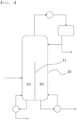
FIG. 1 is a process flow diagram of a multi-component mixture separation system according to an embodiment of the present invention. -
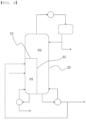
FIG. 2 to 4 are process flow diagrams of a multi-component mixture separation system according to Comparative Examples, respectively. - As described above, the load and life-time of a wind turbine are predicted by mounting a strain gauge in the related art, but such a strain gauge is sensitive to electromagnetic noise, so there is a problem in that installation is difficult. The present disclosure has been designed to estimate the load and life-time of a wind turbine using a vibration sensor that is relatively easy to install.
- Terms and words used in the present specification and claims are not to be construed as a general or dictionary meaning but are to be construed as meaning and concepts meeting the technical ideas of the present invention based on a principle that the inventors can appropriately define the concepts of terms in order to describe their own inventions in best mode.
- In the present invention, the term 'stream' may mean a flow of a fluid in a process, and may also mean a fluid itself flowing in a pipe. Specifically, the stream may mean both the fluid itself and the flow of the fluid flowing within the pipe connecting each device. In addition, the fluid may contain any one or more components of a gas, a liquid, and a solid.
- Hereinafter, the present invention will be described in more detail with reference to
FIG. 1 to help the understanding of the present invention. - According to the present invention, a multi-component mixture separation system is provided. The multi-component mixture separation system includes a
distillation column 10 including a first section D1 and a second section D2 separated by apartition wall 11, and aphase separator 20 receiving a lower discharge stream of the second section D2 and separating the stream into an aqueous phase and an oil phase, and refluxing a portion of the separated aqueous phase or oil phase to the first section D1, in which the first section D1 includes achimney tray 13 provided on an upper portion, and the first section D1 is fed with a feed stream containing three or more components to separate high-boiling point component to a lower portion, and a gaseous component moves to the second section D2. - Conventionally, a process of separating a desired component from other components in a mixture containing three or more components generated through the existing polymerization reaction and recovering unreacted substances may be achieved by a distillation operation sequence. This sequence may include a distillation column for separating all of low-boiling point components, medium-boiling point components, and high-boiling point components from the desired mixture. In order to separate the desired component from the mixture containing three or more components, two or more distillation columns are required.
- For example, a mixture containing three or more components may be fed to a distillation column of a front stage, the high-boiling point component may be separated into the lower portion in the distillation column of the front stage, the low-boiling point component and the medium-boiling point component may be fed to a distillation column of a rear stage, the low-boiling point component may be separated into an upper portion in the distillation column of the rear stage, and the medium-boiling point component may be separated to the lower portion, respectively. In addition, the mixture containing three or more components may be fed to the distillation column of the front stage, the low-boiling point component may be separated into an upper portion in the distillation column of the front stage, the medium-boiling point component and the high-boiling point component may be separated to the lower portion, the medium-boiling point component and the high-boiling point component may be fed to the distillation column of the rear stage, the medium-boiling point component may be separated into an upper portion in the distillation column of the rear stage, and the high-boiling point component may be separated to the lower portion, respectively.
- As such, in order to separate the mixture containing three or more components, two or more distillation columns may be required, and two or more additional devices may also be required, which causes a problem in that the process becomes complicated, and when a stream moves between the two or more distillation columns, unnecessary cooling and heating may be required, which causes a problem in that the number of devices and energy consumption increase.
- On the other hand, in the present invention, one
distillation column 10 provided with apartition wall 11 is used, and gaseous components move from the first section D1 to the second section D2 of thedistillation column 10. However, the present invention provides a multi-component mixture separation system that prevents the liquefied component from moving from the second section D2 to the first section D1 and controls the feed end of the stream refluxed from thephase separator 20 to thedistillation column 10 to separate the mixture, thereby reducing the number of devices by simplifying the process and preventing unnecessary cooling and heating to save energy. - According to an embodiment of the present invention, the
distillation column 10 may be fed with a feed stream containing three or more components to separate each component. For example, the feed stream may contain 3 to 5 components, 3 to 4 components, or 3 components, and as a specific example, the feed stream may contain 3 components. - The inside of the
distillation column 10 may be separated into two sections by thepartition wall 11. Specifically, thedistillation column 10 may be partitioned into the first section D1 and the second section D2 through apartition wall 11, and the distillation in the first section D1 and the second section D2 may be performed independently. - The
partition wall 11 may be formed to extend upwardly from a lower end of thedistillation column 10, for example, and an upper region of thepartition wall 11 may communicate. - The
partition wall 11 may extend vertically from the lower end of thedistillation column 10 to a height spaced apart from an upper end of thedistillation column 10 without reaching the upper end of thedistillation column 10, for example. Specifically, thepartition wall 11 extends from the lower end of thedistillation column 10 to a certain height in an upper direction, that is, in a longitudinal direction of thedistillation column 10, and the communication between the first section D1 and the second section D2 in the lower region of thedistillation column 10 may be blocked through thepartition wall 11 In this case, the height of thepartition wall 11 may be, for example, 30% or more, 40% or more, 50% or more and 60% or less, 70% or less, or 80% or less of the height of thedistillation column 10. By designing the height of thepartition wall 11 within the above range, it is possible to separate the low-boiling point component, the medium-boiling point component, and the high-boiling point component for each boiling point in one column. According to an embodiment of the present invention, thedistillation column 10 is partitioned through thepartition wall 11, and the first section D1 partitioned through thepartition wall 11 may further include achimney tray 13 provided on the upper portion. Thechimney tray 13 may be formed to correspond to an upper area of the first section D1 partitioned by thepartition wall 11. - The
chimney tray 13 may include a plurality of chimneys communicating the gaseous component rising from the lower region of thechimney tray 13 to the upper region, and prevent the liquefied component that may be accumulated in thechimney tray 13 from penetrating into the lower region of thechimney tray 13. Through this, thechimney tray 13 may move the gaseous component from the first section D1 to the second section D2 of thedistillation column 10, but prevent the liquefied component from moving from the second section D2 to the first section D1 Specifically, the communication of the liquefied component may be blocked between the first section D1 and the second section D2 of thedistillation column 10 through thechimney tray 13, and the gaseous component may be made to communicate only from the first section D1 to the second section D2 of thedistillation column 10. In this way, the gaseous component of the first section D1 of thedistillation column 10 moves directly to the second section D2 without a separate condensation and heating step, thereby preventing the use of unnecessary energy to save energy used in the process. - When the
distillation column 10 is partitioned into the first section D1 and the second section D2 through thepartition wall 11, thepartition wall 11 and thechimney tray 13 may be described mainly. For example, the first section D1 of thedistillation column 10 may mean a section positioned in the lower portion with respect to thechimney tray 13, and as a more specific example, may mean a section partitioned through thepartition wall 11 on the side while positioned in the lower portion with respect to thechimney tray 13. In addition, the second section D2 of thedistillation column 10 may mean a section positioned in the upper portion with respect to thechimney tray 13, and as a more specific example, may mean a section partitioned through thepartition wall 11 while positioned in the upper portion with respect to thechimney tray 13. - According to an embodiment of the present invention, the first section D1 may further include a
liquid distribution device 14 provided under thechimney tray 13. Theliquid distribution device 14 may serve to evenly spread the liquid material of the upper portion to the lower portion, and may communicate the gaseous component of the lower portion to the upper portion. Specifically, thechimney tray 13 is provided above the first section D1, so that the liquefied component falling from the upper portion to the lower portion of the first section D1 does not exist. Therefore, for the separation of the feed stream in the first section D1, theliquid distribution device 14 is disposed, and the refluxed stream from thephase separator 20 is fed to a position between thechimney tray 13 and theliquid distribution device 14, and thus, liquefied components may be distributed and sprayed to the lower portion of theliquid distribution device 14. In this case, the substance is transferred by bringing the gaseous component boiled in the lower portion of theliquid distribution device 14 into contact with the liquid component sprayed to the lower portion through theliquid distribution device 14, so the separation may effectively occur. - According to an embodiment of the present invention, the feed stream containing three or more components fed to the
distillation column 10 may be fed to a position lower than theliquid distribution device 14 provided in the first section D1 of thedistillation column 10. In this case, the feed stream may contain the low-boiling point component, the medium-boiling point component, and the high-boiling point component for each boiling point. - The feed stream fed to the
distillation column 10 is distilled in the first section D1, and the vaporized gaseous component rising through the distillation may pass through thechimney tray 13 to move to the second section D2. In addition, the liquefied component in the first section D1 of thedistillation column 10 may be separated into the lower portion of thedistillation column 10, and the lower discharge stream separated into the lower portion in the first section D1 of thedistillation column 10 may contain the high-boiling point component of the feed stream. In this case, the operating condition of the first section D1 is that the high-boiling point component in the feed stream may be separated into the lower portion, and the medium-boiling point component and the low-boiling point component may be vaporized and raised to the upper portion of the first section D1 and may be appropriately adjusted to move to the second section D2. - The lower discharge stream of the first section D1 is partially refluxed through the conventional reboiler, and the remaining components may be recovered.
- The gaseous component moving to the upper portion of the first section D1 of the
distillation column 10 may move to the second section D2 and subjected to additional distillation. In this case, the gaseous component moving to the second section D2 may contain the medium-boiling point component and the low-boiling point component of the feed stream. The medium-boiling point component and the low-boiling point component may be separated through the distillation in the second section D2, and specifically, the low-boiling point component may be separated into the upper portion of the second section D2, and the medium-boiling point component may be separated into the lower portion. - The upper discharge stream discharged to the upper portion of the second section D2 may contain the low-boiling point component of the feed stream. In this case, after the upper discharge stream of the second section D2 may be condensed in the conventional manner, some of the stream may be refluxed and the remaining stream may be recovered.
- The lower discharge stream separated into the lower portion of the second section D2 of the
distillation column 10 is fed to thephase separator 20, and then, the medium-boiling point component may be separated from any one or more of the aqueous phase and the oil phase separated in thephase separator 20. For example, some of the lower discharge stream of the second section D2 of thedistillation column 10 may be refluxed through the conventional reboiler, and the remaining stream may be fed to thephase separator 20. In this case, the remaining stream other than the stream refluxed through the reboiler may pass through, for example, a cooler 12, and then, may be fed to thephase separator 20. The cooler 12 may cool the stream fed to thephase separator 20. - The
phase separator 20 may be a device for separating an aqueous phase and an oil phase. For example, it is possible to separate the aqueous phase and the oil phase of the lower discharge stream of the second section D2 of thedistillation column 10, and reflux some of the separated aqueous phase or oil phase to the first section D1 of thedistillation column 10. In this case, some streams of the separated aqueous phase and oil phase may be refluxed to the first section D1 of thedistillation column 10, and the medium-boiling point component may be separated from and recovered to streams other than the stream refluxed to the first section D1. As a specific example, some of the aqueous phase may be refluxed to the first section D1, and the medium-boiling point component may be separated from the remaining aqueous phase and oil phase not refluxed to the first section D1 of the aqueous phase. - The stream refluxed from the
phase separator 20 to the first section D1 of thedistillation column 10 may be fed to a position higher than a height at which the feed stream is fed in the first section D1. In this case, it is possible to effectively separate by maximizing the substance transfer effect in the first section D1. - The stream refluxed from the
phase separator 20 to the first section D1 of thedistillation column 10 may be refluxed to a position between thechimney tray 13 and theliquid distribution device 14 provided above the first section D1. Specifically, the stream refluxed from thephase separator 20 to the first section D1 of thedistillation column 10 may be refluxed to a position lower than thechimney tray 13 provided above the first section D1 and higher than theliquid distribution device 14. In this case, the liquefied stream refluxed from thephase separator 20 may be prevented from flowing out to the second section D2, and the liquefied stream refluxed from thephase separator 20 may be evenly sprayed to the lower portion using theliquid distribution device 14, thereby further increasing the separation effect through the substance transfer. - According to an embodiment of the present invention, the multi-component mixture separation system can be used to separate each desired component from crude hydroxypivaldehyde, crude phenol, crude isopropyl alcohol, crude acrylic acid, and the like. As a specific example, the multi-component mixture separation system may be used to separate each component from crude hydroxypivaldehyde containing hydroxypivaldehyde and iso-butylaldehyde.
- Specifically, the hydroxypivaldehyde (HPA) is prepared by an aldol condensation reaction between iso-butylaldehyde (i-BAL) and an aqueous formaldehyde solution, and the crude hydroxypivaldehyde produced through the aldol condensation reaction may contain hydroxypivaldehyde, unreacted iso-butylaldehyde, and by-products as the desired products. In this case, the aldol condensation reaction may be performed under the conventional hydroxypivaldehyde production conditions, may be performed in the presence of a catalyst, and if necessary, an additive may be used.
- The crude hydroxypivaldehyde may be fed to the first section D1 of the
distillation column 10 as a feed stream, the hydroxypivaldehyde may be separated into the lower portion of the first section D1 through the distillation in the first section D1, and the unreacted iso-butylaldehyde and by-products pass through thechimney tray 13 as gaseous components and move directly to the second section D2 to save the energy required for the unnecessary cooling and heating. - In the second section D2 of the
distillation column 10, the unreacted iso-butylaldehyde may be separated into the upper portion, and the lower discharge stream may be fed to thephase separator 20 through the reboiler and the cooler 12. - The height of the
partition wall 11 provided in thedistillation column 10 may be appropriately adjusted according to the components of the feed stream. - The aqueous phase and the oil phase are separated in the
phase separator 20, and some of the separated aqueous phase may be refluxed to the first section D1 of thedistillation column 10, more specifically, a height positioned between thechimney tray 13 of the first section D1 and theliquid distribution devices 14. In addition, the by-products may be separated from the aqueous phase and the oil phase that are not refluxed to the first section D1 in thephase separator 20. - The stream fed to the
phase separator 20 contains the by-products, and a small amount of hydroxypivaldehyde may be contained in the aqueous phase component of the byproduct. The oil phase and the aqueous phase may be separated by thephase separator 20, and some of the aqueous phase may be recovered and refluxed to the first section D1 of thedistillation column 10, and may be further subjected to the distillation process to be recovered to the lower portion of the first section D1. As a result, it is possible to increase the production of the hydroxypivaldehyde, and prevent the by-products produced by the aldol condensation reaction from increasing. - Hereinabove, the multi-component mixture separation system according to the present invention has been shown in the description and drawings, but the above drawings and the description describe and illustrate only the essential components for understanding the present invention. In addition to the processes and apparatus illustrated in the above description and drawings, processes and apparatus not separately described and shown may be appropriately applied and used to implement the multi-component mixture separation system according to the present invention.
- Hereinafter, the present invention will be described in more detail with through Examples. However, the following examples are for illustrating the present invention, and it is clear to those skilled in the art that various changes and modifications are possible within the scope and spirit of the present invention, and the scope of the present invention is not limited only thereto.
- As in the process flow diagram illustrated in
FIG. 1 , a multi-component mixture separation system was simulated using Aspen Plus of Aspen Company. - Specifically, crude hydroxypivaldehyde was fed as a feed stream to a first section D1 of a
distillation column 10. In this case, the feed stream contains hydroxypivaldehyde, unreacted iso-butylaldehyde and by-products. In addition, thedistillation column 10 was partitioned into a first section D1 and a second section D2 through apartition wall 11, achimney tray 13 was provided above the first section D1, aliquid distribution device 14 was provided under thechimney tray 13, and the feed stream was fed to a lower position than theliquid distribution device 14. - Some of the lower discharge stream from the first section D1 of the
distillation column 10 was refluxed by using a reboiler, hydroxypivaldehyde was separated into the remaining stream, and the gaseous component moved directly to the second section D2. - In the second section D2, some of the upper discharge stream was refluxed by using a condenser, unreacted iso-butylaldehyde was separated into the remaining stream, and by-products were separated into a lower portion.
- Some of the lower discharge stream of the second section D2 containing the by-products was refluxed by using the reboiler and the remaining stream was fed to the
phase separator 20 through the cooler 12. - An oil phase and an aqueous phase were separated by the
phase separator 20, some of the aqueous phase was fed to a position between thechimney tray 13 and theliquid distribution device 14 of the first section D1 of thedistillation column 10, and the by-products were separated into the remaining aqueous and oil phases. - Results of measuring a recovery rate of hydroxypivaldehyde (HPA) recovered from the lower portion of the first section D1 of the
distillation column 10, a recovery rate of iso-butylaldehyde (i-BAL) recovered from the upper portion of the second section D2, energy consumption used in thedistillation column 10, and content of 2,2,4-trimethyl-1,3-pentanediol (TMPD) in the lower discharge stream of the first section D1 separating hydroxypivaldehyde were shown in the following Table 1. - As in the process flow diagram illustrated in
FIG. 2 , simulations were performed using Aspen Plus manufactured by Aspen Corporation. - Specifically, crude hydroxypivaldehyde was fed as a feed stream to the
first distillation column 100. At this time, the components of the feed stream are the same as in Example 1. - Some of a lower discharge stream of the
first distillation column 100 was refluxed by using a reboiler, and hydroxypivaldehyde was recovered to the remaining steam, an upper discharge stream was fed to thecondenser 110 for condensing and then fed to aphase separator 120, some of an aqueous phase in thephase separator 120 was refluxed to afirst distillation column 100, and the aqueous phase and oil phase not refluxed to thefirst distillation column 100 were fed to asecond distillation column 200. - In the
second distillation column 200, some of the upper discharge stream was refluxed by using the reboiler, iso-butylaldehyde was recovered to the remaining stream, some of the lower discharge stream was refluxed by using the reboiler, and the by-products were separated into the remaining stream. - Results of measuring a recovery rate of hydroxypivaldehyde recovered from a lower portion of the
first distillation column 100, a recovery rate of iso-butylaldehyde recovered from an upper portion of thesecond distillation column 200, energy consumption used in thefirst distillation column 100 and thesecond distillation column 200, and content of 2,2,4-trimethyl-1,3-pentanediol (TMPD) in the lower discharge stream of thefirst distillation column 100 separating the hydroxypivaldehyde were shown in the following Table 1. - As in the process flow diagram illustrated in
FIG. 3 , simulations were performed using Aspen Plus manufactured by Aspen Corporation. - Specifically, crude hydroxypivaldehyde was fed as a feed stream to a first section D1 of a
distillation column 10. At this time, the components of the feed stream are the same as in Example 1. In addition, thedistillation column 10 was partitioned into a first section D1 and a second section D2 through apartition wall 11. - Some of the lower discharge stream of the first section D1 was refluxed by using a reboiler, and hydroxypivaldehyde was separated into the remaining stream.
- Some of the upper discharge stream of the
distillation column 10 was refluxed by using a condenser, and unreacted iso-butylaldehyde was separated into the remaining stream. - Some of the lower discharge stream of the second section D2 was refluxed by using a reboiler, and by-products were separated into the remaining stream.
- Results of measuring a recovery rate of hydroxypivaldehyde (HPA) recovered from the lower portion of the first section D1 of the
distillation column 10, a recovery rate of iso-butylaldehyde (i-BAL) recovered to the upper portion of thedistillation column 10, energy consumption used in thedistillation column 10, and content of 2,2,4-trimethyl-1,3-pentanediol (TMPD) in the lower discharge stream of the first section D1 separating hydroxypivaldehyde were shown in the following Table 1. - As in the process flow diagram illustrated in
FIG. 4 , simulations were performed using Aspen Plus manufactured by Aspen Corporation. - Specifically, crude hydroxypivaldehyde was fed as a feed stream to a first section D1 of a
distillation column 10. At this time, the components of the feed stream are the same as in Example 1. In addition, thedistillation column 10 was partitioned into a first section D1 and a second section D2 through apartition wall 11, achimney tray 13 was provided above the first section D1, and the feed stream was fed to a position lower than thechimney tray 13. - Hydroxypivaldehyde was separated into the lower portion in the first section D1 of the
distillation column 10, and the gaseous component moved directly to the second section D2. - Some of the upper discharge stream of the second section D2 was refluxed by using a condenser, and unreacted iso-butylaldehyde was separated into the remaining stream.
- Some of the lower discharge stream of the second section D2 was refluxed using a reboiler and by-products were separated into the remaining stream, and some of the remaining stream was branched and refluxed to the first section D1.
- Results of measuring a recovery rate of hydroxypivaldehyde (HPA) recovered from the lower portion of the first section D1 of the
distillation column 10, a recovery rate of iso-butylaldehyde (i-BAL) recovered to the upper portion of thedistillation column 10, energy consumption used in thedistillation column 10, and content of 2,2,4-trimethyl-1,3-pentanediol (TMPD) in the lower discharge stream of the first section D1 separating hydroxypivaldehyde were shown in the following Table 1.[Table 1] Example 1 Comparativ e Example 1 Comparativ e Example 2 Comparati ve Example 3 HPA recovery rate (%) 99.994 99.994 99.994 99.994 i-BAL recovery rate (%) 91.123 91.123 91.123 91.123 Energy consumption (%) 81.1 100 81.1 81.1 TMPD content (wt%) 0.001 0.001 0.1 0.1 - In the above Table 1, the energy consumption was indicated by converting the energy consumption measured in Example 1 and Comparative Examples 1 to 3, respectively, into a percentage with respect to the energy consumption used in Comparative Example 1.
- In addition, the HPA recovery rate represents the ratio of the recovered content of hydroxypivaldehyde to the content of hydroxypivaldehyde included in the feed stream, and the i-BAL recovery rate represents the recovered content of iso-butylaldehyde to the content of iso-butylaldehyde contained in the feed stream.
- In the above Table 1, in the case of Example 1, the multi-component mixture separation system using one
distillation column 10 and aphase separator 20 equipped with apartition wall 11 according to the present invention was used, and it could be confirmed that the energy consumption was reduced compared to Example 1, and the recovery rate of the recovered hydroxypivaldehyde and the recovery rate of iso-butylaldehyde were the same as those of Comparative Example 1. - In comparison, in the case of Comparative Example 1, two distillation columns were used, and it could be confirmed that the upper discharge stream of the
first distillation column 100 was condensed and then supplied to thephase separator 120 for phase separation, and the energy consumption increased compared to the Example by supplying an aqueous phase and an oil phase that were not refluxed to thefirst distillation column 100 among the phase-separated aqueous phase to thesecond distillation column 200 and heating the aqueous and oil phases again. - In addition, as in the above embodiment, in the case of Comparative Example 2 in which one
distillation column 10 partitioned by a partition wall was used, but thechimney tray 13 was not provided above the first section D1, and there was no stream refluxed to the first section D1 due to the absence of thephase separator 20, the liquefied component containing a reactive organic material was introduced into the first section D1 from the second section D2 through an upper space of thedistillation column 10, and the generation amount of TMPD, which was difficult to separate from hydroxypivaldehyde in the rear-stage process, increased. Specifically, in the case of Comparative Example 2, the content of TMPD in the lower discharge stream of the first section D1 separating hydroxypivaldehyde increases, so there is a problem in that it is difficult to control the quality of the product in the subsequent process. - In addition, as in the above embodiment, even in the case of Comparative Example 3 in which one
distillation column 10 partitioned by a partition wall and thechimney tray 13 were provided in the first section D1 of the distillation column, but thephase separator 20 was not provided, the liquefied component from which the reactive organic material was not removed was introduced into the first section D1 due to the absence of thephase separator 20 to increase the content of the TMPD in the lower discharge stream of the first section D1 separating hydroxypivaldehyde, so there is a problem in that it is difficult to control the quality of the product in the subsequent process.
Claims (11)
- A multi-component mixture separation system, comprising:a distillation column including a first section and a second section separated by a partition wall; anda phase separator receiving a lower discharge stream of the second section and separating the stream into an aqueous phase and an oil phase, and refluxing a portion of the separated aqueous phase or oil phase to the first section,wherein the first section includes a chimney tray provided on an upper portion, andthe first section is supplied with a feed stream containing three or more components to separate high-boiling point component to a lower portion, and a gaseous component moves to the second section.
- The multi-component mixture separation system of claim 1, wherein the partition wall extends upwardly from a lower end of the distillation column.
- The multi-component mixture separation system of claim 1, wherein the stream refluxed from the phase separator to the first section is fed to a position higher than a height to which the feed stream is fed.
- The multi-component mixture separation system of claim 1, wherein the chimney tray is formed to correspond to an upper area of the first section partitioned by the partition wall.
- The multi-component mixture separation system of claim 1, further comprising:
a liquid distribution device provided under the chimney tray. - The multi-component mixture separation system of claim 5, wherein the stream refluxed from the phase separator to the first section is refluxed to a position between the chimney tray and the liquid distribution device.
- The multi-component mixture separation system of claim 5, wherein the feed stream is fed to a position lower than the liquid distribution device.
- The multi-component mixture separation system of claim 1, wherein the second section of the distillation column separates a low-boiling point component to an upper portion, feeds the lower discharge stream to the phase separator, and then separates a medium-boiling point component from any one or more of the aqueous phase and the oil phase separated in the phase separator.
- The multi-component mixture separation system of claim 1, wherein the phase separator refluxes a portion of the separated aqueous phase to the first section of the distillation column.
- The multi-component mixture separation system of claim 1, wherein the feed stream is crude hydroxypivaldehyde containing hydroxypivaldehyde and iso-butylaldehyde.
- The multi-component mixture separation system of claim 10, wherein the first section of the distillation column separates hydroxypivaldehyde to a lower portion, and the second section separates iso-butylaldehyde to an upper portion.
Applications Claiming Priority (2)
| Application Number | Priority Date | Filing Date | Title |
|---|---|---|---|
| KR1020210122586A KR102900665B1 (en) | 2021-09-14 | 2021-09-14 | Multi-component mixture separation system |
| PCT/KR2022/008577 WO2023043003A1 (en) | 2021-09-14 | 2022-06-16 | Multi-component mixture separation system |
Publications (2)
| Publication Number | Publication Date |
|---|---|
| EP4176952A1 true EP4176952A1 (en) | 2023-05-10 |
| EP4176952A4 EP4176952A4 (en) | 2024-02-28 |
Family
ID=85603068
Family Applications (1)
| Application Number | Title | Priority Date | Filing Date |
|---|---|---|---|
| EP22850567.3A Pending EP4176952A4 (en) | 2021-09-14 | 2022-06-16 | MULTI-COMPONENT MIXTURE SEPARATION SYSTEM |
Country Status (5)
| Country | Link |
|---|---|
| US (1) | US12296288B2 (en) |
| EP (1) | EP4176952A4 (en) |
| KR (1) | KR102900665B1 (en) |
| CN (1) | CN116323537B (en) |
| WO (1) | WO2023043003A1 (en) |
Families Citing this family (4)
| Publication number | Priority date | Publication date | Assignee | Title |
|---|---|---|---|---|
| KR20250008194A (en) | 2023-07-07 | 2025-01-14 | 주식회사 엘지화학 | Separation system |
| US20260084077A1 (en) * | 2023-09-19 | 2026-03-26 | Lg Chem, Ltd. | Refinery apparatus |
| EP4640663A1 (en) * | 2023-11-15 | 2025-10-29 | Lg Chem, Ltd. | Method for preparing isopropyl alcohol |
| JP2026506587A (en) * | 2023-11-15 | 2026-02-25 | エルジー・ケム・リミテッド | How is isopropyl alcohol produced? |
Family Cites Families (25)
| Publication number | Priority date | Publication date | Assignee | Title |
|---|---|---|---|---|
| JP3541542B2 (en) * | 1995-02-13 | 2004-07-14 | 三菱化学株式会社 | Method for producing dimerized aldehyde |
| JP3543447B2 (en) * | 1995-11-07 | 2004-07-14 | 三菱化学株式会社 | Method for producing dimerized aldehyde |
| US5755933A (en) * | 1995-07-24 | 1998-05-26 | The M. W. Kellogg Company | Partitioned distillation column |
| JP3748667B2 (en) * | 1996-05-30 | 2006-02-22 | 協和発酵ケミカル株式会社 | Distillation method and distillation apparatus |
| KR100231644B1 (en) | 1996-10-22 | 1999-11-15 | 성재갑 | Process for producing neopentylglycol |
| JP3856974B2 (en) * | 1999-02-17 | 2006-12-13 | 株式会社日本触媒 | Distillation method and distillation apparatus |
| US6930206B1 (en) * | 2001-07-05 | 2005-08-16 | Catalytic Distillation Technologies | Process and apparatus for catalytic distillations |
| DE10260092A1 (en) * | 2002-12-19 | 2004-07-01 | Basf Ag | Process for the purification of isocyanates |
| DE102005032430A1 (en) | 2005-07-12 | 2007-01-25 | Bayer Materialscience Ag | Process for the preparation of toluenediamine |
| KR101092199B1 (en) * | 2010-10-29 | 2011-12-09 | 코오롱플라스틱 주식회사 | 1.3,5-How to prepare trioxane |
| KR101530102B1 (en) | 2010-12-29 | 2015-06-18 | 주식회사 엘지화학 | Dividing wall column for purification of neopentyl glycol, and purification method of neopentyl glycol |
| SG11201506454TA (en) * | 2013-02-21 | 2015-09-29 | Gtc Technology Us Llc | Separation processes using divided columns |
| DE102013207282A1 (en) | 2013-04-22 | 2014-11-06 | Wacker Chemie Ag | Process and apparatus for the distillative separation of a three- or multi-component mixture |
| DE102013214765A1 (en) | 2013-07-29 | 2015-01-29 | Wacker Chemie Ag | Process and apparatus for the distillative separation of a three- or multi-component mixture |
| KR101959467B1 (en) * | 2015-07-02 | 2019-07-02 | 주식회사 엘지화학 | Distillation device |
| KR101952690B1 (en) | 2015-09-07 | 2019-02-27 | 주식회사 엘지화학 | Apparatus and method for preparing glycol |
| US10399004B2 (en) * | 2016-09-08 | 2019-09-03 | Eastman Chemical Company | Thermally integrated distillation systems and processes using the same |
| US10526545B2 (en) * | 2016-10-28 | 2020-01-07 | Uop Llc | Processes for stripping contaminants from multiple effluent streams |
| FR3069538B1 (en) * | 2017-07-25 | 2020-05-15 | Arkema France | PROCESS FOR THE PURIFICATION OF (METH) ACRYLIC ESTERS. |
| KR102387476B1 (en) * | 2017-11-17 | 2022-04-14 | 주식회사 엘지화학 | Process for Purification of Raffinate-2 streams |
| US10792585B2 (en) | 2018-03-29 | 2020-10-06 | Uop Llc | Folded fractionation column and process |
| US10792583B2 (en) * | 2018-03-29 | 2020-10-06 | Uop Llc | Process and apparatus for controlling the split of liquid reflux in a divided wall column |
| US10688408B2 (en) | 2018-07-26 | 2020-06-23 | Uop Llc | Dividing wall column with vapor separation |
| US10377690B1 (en) * | 2018-08-22 | 2019-08-13 | Eastman Chemical Company | Method for catalytic production of refined enal products from an aldehyde feed stream using a single enclosed unit |
| CN111298471B (en) * | 2020-03-30 | 2025-01-24 | 吴嘉 | A dividing wall distillation tower and distillation method for separation of complex multi-component systems |
-
2021
- 2021-09-14 KR KR1020210122586A patent/KR102900665B1/en active Active
-
2022
- 2022-06-16 CN CN202280006250.9A patent/CN116323537B/en active Active
- 2022-06-16 US US18/020,873 patent/US12296288B2/en active Active
- 2022-06-16 EP EP22850567.3A patent/EP4176952A4/en active Pending
- 2022-06-16 WO PCT/KR2022/008577 patent/WO2023043003A1/en not_active Ceased
Also Published As
| Publication number | Publication date |
|---|---|
| US20240299859A1 (en) | 2024-09-12 |
| WO2023043003A1 (en) | 2023-03-23 |
| CN116323537A (en) | 2023-06-23 |
| EP4176952A4 (en) | 2024-02-28 |
| CN116323537B (en) | 2025-07-22 |
| KR20230039362A (en) | 2023-03-21 |
| US12296288B2 (en) | 2025-05-13 |
| KR102900665B1 (en) | 2025-12-15 |
Similar Documents
| Publication | Publication Date | Title |
|---|---|---|
| US12296288B2 (en) | Multi-component mixture separation system | |
| KR101191112B1 (en) | Dividing wall column for production of high purity 2-ethylhexanol and distillating method using thereof | |
| KR101496488B1 (en) | Dividing wall column for production of high purity 2-ethylhexyl-acrylate, and preparation method of high purity 2-ethylhexyl-acrylate | |
| JP5822199B2 (en) | Separation wall type distillation column for producing high-purity normal butanol and normal butanol distillation method | |
| KR101530102B1 (en) | Dividing wall column for purification of neopentyl glycol, and purification method of neopentyl glycol | |
| KR20100105498A (en) | Dividing wall column for production of high purity acrylic acid and distillating method using thereof | |
| CN109179542B (en) | Distillation system and distillation process for glycol and diethylene glycol in polyol waste liquid | |
| CN111298471A (en) | A kind of dividing wall rectification column and rectification method for separation of complex multi-component system | |
| KR101959467B1 (en) | Distillation device | |
| US7862783B2 (en) | Separation process for methyl acetate hydrolysis and apparatus thereof | |
| CN107837556B (en) | Operation control method of dividing wall rectifying tower | |
| CN107837555B (en) | Quality control method of dividing wall rectifying tower | |
| CN107837552B (en) | Operation and control method of dividing wall rectifying tower | |
| CN107080966A (en) | A kind of rectifying tower with bulkhead and bulkhead rectificating method | |
| KR101724072B1 (en) | Method of purificaiton for vinyl acetic acid using dividing wall column | |
| KR101251176B1 (en) | Dividing wall column for n-butanol recovery | |
| CN216703371U (en) | Integrated form reaction unit | |
| CN109081821A (en) | Furfural recovery device and recovery method for ceramic production condensate | |
| CN102897830A (en) | Recovery method of polyolefin catalyst mother liquid | |
| CN107837553A (en) | The method of controlling operation thereof of divided wall column | |
| US20080264772A1 (en) | Method and apparatus for esterification | |
| EP4640663A1 (en) | Method for preparing isopropyl alcohol | |
| KR20250071834A (en) | Method for preparing isopropyl alcohol | |
| CN114805057B (en) | A production method for producing butyric anhydride by bulkhead reaction distillation | |
| KR20250037132A (en) | Method for preparing isopropyl alcohol |
Legal Events
| Date | Code | Title | Description |
|---|---|---|---|
| STAA | Information on the status of an ep patent application or granted ep patent |
Free format text: STATUS: UNKNOWN |
|
| STAA | Information on the status of an ep patent application or granted ep patent |
Free format text: STATUS: THE INTERNATIONAL PUBLICATION HAS BEEN MADE |
|
| PUAI | Public reference made under article 153(3) epc to a published international application that has entered the european phase |
Free format text: ORIGINAL CODE: 0009012 |
|
| STAA | Information on the status of an ep patent application or granted ep patent |
Free format text: STATUS: REQUEST FOR EXAMINATION WAS MADE |
|
| 17P | Request for examination filed |
Effective date: 20230206 |
|
| AK | Designated contracting states |
Kind code of ref document: A1 Designated state(s): AL AT BE BG CH CY CZ DE DK EE ES FI FR GB GR HR HU IE IS IT LI LT LU LV MC MK MT NL NO PL PT RO RS SE SI SK SM TR |
|
| A4 | Supplementary search report drawn up and despatched |
Effective date: 20240129 |
|
| RIC1 | Information provided on ipc code assigned before grant |
Ipc: C07C 45/82 20060101ALI20240123BHEP Ipc: B01D 17/02 20060101ALI20240123BHEP Ipc: B01D 3/14 20060101ALI20240123BHEP Ipc: C07C 47/02 20060101ALI20240123BHEP Ipc: C07C 47/19 20060101ALI20240123BHEP Ipc: C07C 45/79 20060101ALI20240123BHEP Ipc: B01D 3/32 20060101AFI20240123BHEP |
|
| DAV | Request for validation of the european patent (deleted) | ||
| DAX | Request for extension of the european patent (deleted) |