EP4176703A1 - Piston lock system for agricultural equipment - Google Patents
Piston lock system for agricultural equipment Download PDFInfo
- Publication number
- EP4176703A1 EP4176703A1 EP22205794.5A EP22205794A EP4176703A1 EP 4176703 A1 EP4176703 A1 EP 4176703A1 EP 22205794 A EP22205794 A EP 22205794A EP 4176703 A1 EP4176703 A1 EP 4176703A1
- Authority
- EP
- European Patent Office
- Prior art keywords
- cylinder
- piston
- rod
- lock pin
- lock
- Prior art date
- Legal status (The legal status is an assumption and is not a legal conclusion. Google has not performed a legal analysis and makes no representation as to the accuracy of the status listed.)
- Pending
Links
- 230000007246 mechanism Effects 0.000 description 7
- 239000000463 material Substances 0.000 description 6
- 230000000712 assembly Effects 0.000 description 3
- 238000000429 assembly Methods 0.000 description 3
- 241001124569 Lycaenidae Species 0.000 description 1
- 230000006978 adaptation Effects 0.000 description 1
- 239000000853 adhesive Substances 0.000 description 1
- 230000001070 adhesive effect Effects 0.000 description 1
- 230000000903 blocking effect Effects 0.000 description 1
- 238000006073 displacement reaction Methods 0.000 description 1
- 238000005516 engineering process Methods 0.000 description 1
- 239000012530 fluid Substances 0.000 description 1
- 238000003306 harvesting Methods 0.000 description 1
- 230000002452 interceptive effect Effects 0.000 description 1
- 238000012986 modification Methods 0.000 description 1
- 230000004048 modification Effects 0.000 description 1
- 238000003466 welding Methods 0.000 description 1
Images



Classifications
-
- A—HUMAN NECESSITIES
- A01—AGRICULTURE; FORESTRY; ANIMAL HUSBANDRY; HUNTING; TRAPPING; FISHING
- A01D—HARVESTING; MOWING
- A01D41/00—Combines, i.e. harvesters or mowers combined with threshing devices
- A01D41/12—Details of combines
- A01D41/14—Mowing tables
- A01D41/145—Header lifting devices
-
- A—HUMAN NECESSITIES
- A01—AGRICULTURE; FORESTRY; ANIMAL HUSBANDRY; HUNTING; TRAPPING; FISHING
- A01D—HARVESTING; MOWING
- A01D61/00—Elevators or conveyors for binders or combines
- A01D61/008—Elevators or conveyors for binders or combines for longitudinal conveying, especially for combines
-
- F—MECHANICAL ENGINEERING; LIGHTING; HEATING; WEAPONS; BLASTING
- F15—FLUID-PRESSURE ACTUATORS; HYDRAULICS OR PNEUMATICS IN GENERAL
- F15B—SYSTEMS ACTING BY MEANS OF FLUIDS IN GENERAL; FLUID-PRESSURE ACTUATORS, e.g. SERVOMOTORS; DETAILS OF FLUID-PRESSURE SYSTEMS, NOT OTHERWISE PROVIDED FOR
- F15B15/00—Fluid-actuated devices for displacing a member from one position to another; Gearing associated therewith
- F15B15/20—Other details, e.g. assembly with regulating devices
- F15B15/26—Locking mechanisms
-
- F—MECHANICAL ENGINEERING; LIGHTING; HEATING; WEAPONS; BLASTING
- F15—FLUID-PRESSURE ACTUATORS; HYDRAULICS OR PNEUMATICS IN GENERAL
- F15B—SYSTEMS ACTING BY MEANS OF FLUIDS IN GENERAL; FLUID-PRESSURE ACTUATORS, e.g. SERVOMOTORS; DETAILS OF FLUID-PRESSURE SYSTEMS, NOT OTHERWISE PROVIDED FOR
- F15B15/00—Fluid-actuated devices for displacing a member from one position to another; Gearing associated therewith
- F15B15/20—Other details, e.g. assembly with regulating devices
- F15B15/26—Locking mechanisms
- F15B15/261—Locking mechanisms using positive interengagement, e.g. balls and grooves, for locking in the end positions
-
- F—MECHANICAL ENGINEERING; LIGHTING; HEATING; WEAPONS; BLASTING
- F15—FLUID-PRESSURE ACTUATORS; HYDRAULICS OR PNEUMATICS IN GENERAL
- F15B—SYSTEMS ACTING BY MEANS OF FLUIDS IN GENERAL; FLUID-PRESSURE ACTUATORS, e.g. SERVOMOTORS; DETAILS OF FLUID-PRESSURE SYSTEMS, NOT OTHERWISE PROVIDED FOR
- F15B15/00—Fluid-actuated devices for displacing a member from one position to another; Gearing associated therewith
- F15B15/08—Characterised by the construction of the motor unit
- F15B15/14—Characterised by the construction of the motor unit of the straight-cylinder type
-
- F—MECHANICAL ENGINEERING; LIGHTING; HEATING; WEAPONS; BLASTING
- F15—FLUID-PRESSURE ACTUATORS; HYDRAULICS OR PNEUMATICS IN GENERAL
- F15B—SYSTEMS ACTING BY MEANS OF FLUIDS IN GENERAL; FLUID-PRESSURE ACTUATORS, e.g. SERVOMOTORS; DETAILS OF FLUID-PRESSURE SYSTEMS, NOT OTHERWISE PROVIDED FOR
- F15B15/00—Fluid-actuated devices for displacing a member from one position to another; Gearing associated therewith
- F15B15/20—Other details, e.g. assembly with regulating devices
- F15B15/26—Locking mechanisms
- F15B2015/267—Manual locking or release
Definitions
- Agricultural equipment such as combine harvesters that are used to gather agricultural crops, typically have a header that is configured to remove the crop material from the ground, and a feeder that conveys the crop material to the main body of the vehicle for processing and temporary storage.
- the feeder typically is encased in a feeder housing, which may be connected to the vehicle chassis by hydraulic cylinders, in order to allow the header to move relative to the chassis. At times, it may be necessary to extend the hydraulic cylinders to raise the header out of contact with the ground. For example, it may be desirable to raise the header during road transport and other non-harvesting movements, and to allow service of the header and related parts. Under these circumstances (and especially during service), it may be desirable to lock the feeder in the raised position to inhibit accidental lowering of the feeder and header.
- One way to lock the feeder in the raised position is to place a blocking member around the piston member of a hydraulic actuator that connects the feeder (and thus the header) to the vehicle chassis.
- a lock in the form of a rigid rod or shaft having an open slot along the side can be slipped over the piston when it is extended from the cylinder, with the ends of the lock terminating adjacent to the two exposed ends of the piston.
- One end of the lock rests against the end face of the cylinder, and the other end of the lock rests against the end fitting of the cylinder (or another adjacent structure, such as a clevis into which the end fitting is installed), thereby preventing the piston from retracting into the cylinder.
- U.S. Pat. No. 4,529,215 discloses a cylinder lock member in the form of two straps that are pivotally connected to the free end of the piston. Multiple lock members may be connected to each other by a pivot shaft that extends between the cylinder assemblies. In use, the lock members rotate out of the plane defined by the cylinder assemblies. This requires a large clear space adjacent to the cylinder assemblies, and limits or prohibits the applicability of this mechanism when there is no free space to allow the lock members to rotate. Thus, such a mechanism is only feasible when there is sufficient room for the system.
- a piston lock system comprising: a first cylinder extending from a first fixed cylinder end to a first free cylinder end; a first rod receiver fixed to the first cylinder; a first piston extending through the first free cylinder end from a first sliding piston end contained in the first cylinder to a first free piston end located outside the first cylinder; a first rod extending, parallel to the first piston, from a first fixed rod end secured to move with the first free piston end to a first sliding rod end located within the first rod receiver, wherein the first piston and first rod are movable relative to the first cylinder and first rod receiver between a first retracted position and a first extended position, with the first free piston end and first fixed rod end being farther from the first free cylinder end in the first extended position than in the first retracted position; and a first lock pin mounted to the first rod receiver and movable between a first unlocked position in which the first lock pin does not intersect a path of the first rod, and a first locked position in which
- an agricultural combine comprising: a chassis configured for movement on a surface; a feeder housing pivotally connected to the chassis; and a piston lock system as described in the foregoing aspect and examples.
- Exemplary embodiments of the present invention provide piston lock systems which may be used in agricultural equipment (e.g., combines, windrowers, etc.), or in other environments.
- agricultural equipment e.g., combines, windrowers, etc.
- the invention is not limited to any particular application except as may be specifically recited in the claims.
- the vehicle 100 includes a chassis 102 that is supported for movement on the ground by wheels 104 (e.g., pneumatic tires or tracked wheels).
- a header assembly 106 is attached to the combine 100 and configured to receive crop material and convey such material to a threshing and separating system 108 located in or on the chassis 102.
- the threshing and separating system 108 separates grain from the remaining crop material (also known as "material other than grain,” “MoG,” or “residue”).
- the separated grain is stored in a hopper 110, and the MoG is evacuated to the trailing path of the vehicle 100 by a spreader 112.
- the header assembly 106 comprises a feeder housing 114 and a header 116.
- the feeder housing 114 is pivotally connected to the chassis 102 at a horizontal pivot 118.
- One or more actuators 120 are connected between the chassis 102 and the feeder housing 114.
- Each actuator comprises a hydraulic cylinder and piston assembly with a piston lock system, such as described in more detail below.
- FIG. 1 The features described in relation to FIG. 1 are generally conventional, except for the actuators, and particularly the piston lock system, and no further explanations of their structures or operations are necessary.
- FIG. 2 a first example of a piston lock system is shown and described in detail.
- the piston lock system is shown installed on a first actuator 120a and a second actuator 120b, but it will be appreciated that features of the piston lock system may be implemented on a single actuator.
- Each actuator 120 comprises a cylinder 200 extending from a fixed cylinder end 202 to a free cylinder end 204, and a piston 206 extending through the free cylinder end 204 from a sliding piston end 208 to a free piston end 210.
- the sliding piston end 208 is contained in the cylinder 200, and the free piston end 210 is located outside the cylinder 200.
- the piston 206 is slidable relative to the cylinder 200 in a manner that is conventional in the art of hydraulic actuators.
- a hydraulic system may include a one or more hydraulic ports 212 that are fluidly connected to the interior of the cylinder, and configured to convey pressurized hydraulic fluid to extend or retract the piston 206 relative to the cylinder 200.
- Such hydraulic systems are conventional, and need not be described in further detail herein.
- At least one rod receiver 214 is fixed to each cylinder 200.
- each cylinder 200 has two rod receivers 214 located on opposite sides of the cylinder 200.
- Each rod receiver 214 comprises a housing-like structure having a longitudinal passage 216a that is oriented in parallel with the sliding direction of the piston 206, and a lateral passage 216b oriented at an angle to the sliding direction of the piston 206. Examples of the longitudinal passage 216a and lateral passage 216b are shown in FIG. 5A .
- the lateral passage 216b includes a wall facing towards the free cylinder end 204, which serves as a surface that bears loads to lock the piston 206 in position. to this end, the lateral passage 216b preferably extends perpendicular to the sliding direction of the piston 206, but this is not strictly required.
- At least one rod 218 is attached to each piston 206.
- Each rod 218 extends, parallel to the piston 206, from a fixed rod end that is secured to the free piston end 210, to a free rod end that extends into a respective rod receiver 214.
- the fixed rod end, and thus the entire rod 218, is configured to move in unison with the free piston end 210.
- the rod 218 may be attached by a bolt, adhesives or welding to a boss extending from a side of the free piston end 210.
- the pistons 206 and rods 218 are telescopically movable relative to the respective cylinders 200 and rod receivers 214 between a retracted position ( FIG. 5A ) and an extended position ( FIG. 5B ).
- the free piston ends 210 and fixed rod ends are farther from the free cylinder ends 204 in the extended position than in the retracted position.
- suitable hydraulic controls may be used to extend and retract the pistons 206 relative to the cylinders 200.
- At least one lock pin 220 is mounted to each cylinder 200.
- a lock pin 220 may be slidingly connected to each rod receiver 214.
- the lock pins 220 are movable between an unlocked position ( FIG. 3A ) in which the lock pins 220 do not intersect a path of the respective rod 218, and a locked position ( FIG. 3B ) in which the lock pin 220 intersects the path of the respective rod 218.
- FIG. 3A unlocked position
- FIG. 3B locked position
- each lock pin 220 is captured between the free end of rod 218 and a wall of the lateral passage 216, and thus prevents the rod 218 and piston 206 from moving from the extended position to the retracted position.
- lock pins 220 may be separately moved between their respective locked and unlocked positions, it is more preferred to provide a mechanism to simultaneously operate all of the lock pins 220. This provides greater assurance that all of the lock pins 220 are properly positioned to prevent the pistons 206 from inadvertently retracting from the extended position towards the retracted position.
- the lock pins 220 associated with each cylinder 200 are connected to each other by a plate 222, to thereby cause them to move in unison.
- lock pins 220 from one actuator 120a are connected to the lock pins 220 of the other actuator 120b by a control link 224 that is configured to simultaneously move the lock pins 220 of the first actuator 120a with the lock pins 220 of the second actuator 120b between their respective locked and unlocked positions
- the control link 224 comprises a central transfer link 226, a first connecting link 228 joining the lock pins 220 of the first actuator 120a to the transfer link 226, and a second connecting link 230 joining the lock pins 220 of the second actuator 120b to the transfer link.
- the transfer link is pivotally mounted at a transfer link pivot 232.
- the transfer link pivot 232 is fixed to move in unison with the actuators 120a, 120b, and thus maintains an appropriate position to anchor the transfer link 226 throughout the range of motion of the entire assembly.
- the transfer link pivot 232 may be secured to one or both cylinders 200 by one or more braces, such as the illustrated cross braces 234.
- the cross braces 234 may be secured to the cylinders 200 by a direct connection or by connection to the rod receivers 214.
- the cylinders 200 When installed on a vehicle 100, the cylinders 200 are configured to be coplanar or parallel throughout their respective ranges of motion. When coplanar, the fixed cylinder ends 202 and free piston ends 210 all lie in a common plane. When parallel, the fixed cylinder ends 202 and free piston ends 210 all lie in a common plane, and the cylinders 200 and pistons 206 are parallel within the common plane. In either case, some variation may occur during regular use due to differential loading and slight differences in hydraulic system operations. In either case, the cylinders 200 define a plane between them, and the transfer link pivot 232 may be oriented with a rotation axis that extends orthogonal to the plane defined between the two cylinders 200.
- the transfer link pivot 232 may comprise a pin or the like that extends orthogonal to this plane. As will be clear from the following explanation of the operation of the control link 224, this orthogonal orientation allows the control link 224 to remain generally within the plane throughout the range of motion, leading to a more compact system.
- the first connecting link 228 and second connecting link 230 are attached by pivots to opposite ends of the transfer link 226, with the transfer link pivot 232 being approximately midway between the connections to the two connecting links 228, 230.
- movement of one connecting link 228 causes a corresponding opposite movement of the other connecting link 230.
- Each connecting link 228, 230 is also connected, at its opposite end, to one of the lock pins 220 or (if used) the lock pin plate 222.
- movement of a lock pin 220 on one actuator 120a causes a simultaneous and opposite movement of a connected lock pin 220 on the other actuator 120b.
- the control link 224 may be operated using any suitable mechanism.
- a handle 236 may be connected to the lock pins 220 or lock pin plate 222 of one actuator 120a.
- the handle 236 is positioned and configured for manual operation by a technician.
- the handle 236 may comprise an elongated bar that is located on a side of the cylinder 200 opposite the control link 224, to allow operation without having to enter the space between the two actuators 120a, 120b.
- the handle 236 also may include a service lock 238 ( FIG. 4B ) to prevent inadvertent operation to move the lock pins 220 from the locked position to the unlocked position.
- the service lock 238 may comprise, for example, a pin that is insertable into a hole in the end of the lock pin 220, to prevent withdrawal from the locked position.
- the control link 224 also may be operated by a remote system, such as described below. Other alternatives and variations will be apparent to persons of ordinary skill in the art in view of the present disclosure.
- FIGS. 3A-4B the operation of the lock pins 220 is shown in more detail.
- FIGS. 3A and 4A show the lock pins 220 in the unlocked position
- FIGS. 3B and 4B show the lock pins 220 in the locked position.
- the control link 224 is located entirely in a space between the two cylinders 200.
- the lock pins 220 of each cylinder move in opposite directions. Specifically, the lock pins 220 for the first actuator 120a move away from the second actuator 120b when moving from the unlocked position to the locked position, and the lock pins 220 for the second actuator 120b move away from the first actuator 120b when moving from the unlocked position to the locked position.
- the reverse operation moves the lock pins 220 to their unlocked positions.
- FIGS. 5A and 5B show an alternative piston lock system.
- the mechanisms are generally the same as in the embodiment of FIGS. 2-4B , so this description addresses the differences between the embodiments.
- the actuator 500 may be any suitable powered motion device, such as a pneumatic, hydraulic or electric telescoping element (e.g., a piston/cylinder assembly).
- the actuator 500 can be operated remotely, either by an automated control system or by a user's direct input.
- the control link 224 is provided in the form of a pushrod 502 that extends to connect the lock pins 220 of the first actuator 120a with the lock pins 220 of the second actuator 120b.
- the lock pins 220 are slidably mounted to the rod receivers 214, and the pushrod 502 is configured to move along an axis A extending between the cylinders 200 of the first and second actuators 120a, 120b. This axis A may extend perpendicular to the cylinders 200, but this is not strictly required.
- the pushrod 502 may be rigidly connected to the lock pins 220, or connected by pivots or other flexible connectors to allow some relative displacement between the two actuators 120a, 120b without interfering with proper operation of the lock pins 220.
- the pushrod 502 also may be connected directly to the lock pins 220, or to a structure that holds the lock pins 220, such as the plate 222 described above.
- the actuator 500 drives one end of the pushrod 502 or one set of lock pins 220, and such motion is transferred to the other lock pins by the pushrod 502.
- the lock pins 220 all move in the same direction between their respective locked and unlocked positions.
- first lock pin or pins 220 of the first actuator 120a move towards the second actuator 120b when moving from the unlocked position to the locked position
- the lock pin or pins 220 of the second actuator 120b move away from the first actuator 120a when moving from the unlocked position to the locked position.
- this embodiment may have a manually-operated handle 236 and/or a powered actuator 500.
- FIGS. 6A and 6B show another alternative embodiment.
- the sliding lock pins 220 of the previous embodiment are replaced by rotating lock pins 220.
- the rotating lock pins 220 are connected by an arm 600 and a pivot 602 to the cylinder 200 and/or rod receiver 214.
- the control link 224 is a pushrod 502 that is operated by a handle 236. If necessary, the pushrod 502 may be connected to the arm 600 by another pivot 604, to allow the pushrod 502 to remain oriented towards a lock pin 220 on an adjacent actuator (not shown in FIGS. 6A and 6B ). In use, the pushrod 236 is moved to rotate the arm 600 and place the lock pin 220 into the lateral passage 216b.
- FIGS. 7A-8B show another embodiment.
- the control link 224 comprises an axle 700 extending from the lock pin 220 of the first actuator 120a to the lock pin of a second actuator (not shown).
- the axle 700 is pivotally mounted to the cylinders 200 (either directly or via the rod receiver 214 or other structure), and configured to rotate about an axis A extending between the actuators 120a, 120b.
- the lock pins 220 are rigidly connected to the axle 700 by one or more offset arms 702, and thus move with the axle 700 through an arcuate path as the axle 700 rotates.
- a handle 236 or other control is provided to rotate the axle 700.
- rotating the axle 700 moves the lock pins 220 between an unlocked position ( FIGS. 7A and 8A ) and a locked position ( FIGS. 7B and 8B ).
- the lock pin 220 in the locked position, is positioned between the rod 218 and an inner face 704 of the rod receiver 214, and preferably in contact with both the inner face 704 and the rod 218 to provide a direct load-bearing path from the rod to the rod receiver 214.
- the lock pin 220 may be connected to the axle 700 or offset arms 702 by a lost-motion mechanism (e.g., a pin that fits into a slot or oversized hole), to allow the lock pin 220 to move slightly to make contact with the surface 704.
- a lost-motion mechanism e.g., a pin that fits into a slot or oversized hole
- FIGS. 9A and 9B show a further embodiment, in which a cam 900 is used to move the lock pin 220 between the locked and unlocked positions.
- the cam 900 is rotatably mounted to the cylinder 200 or rod receiver 214, and includes a helical cam track 902.
- a cam follower 904 such as a pin, is attached to the lock pin 220 (or to a plate 222 or other comparable structure), and positioned within the cam track.
- a handle 236 is provided to rotate the cam 900. Rotating the cam 900 causes the cam track 902 to drive the cam follower 904, thus moving the lock pin 220 between the locked and unlocked positions.
- a pushrod 502 is attached to the lock pin 220 to transfer motion to another lock pin on an adjacent actuator, but this is not strictly required.
- each actuator may have its own cam 900 or cams, and the cams of the actuators may be joined by an axle such as the axle 700 of the embodiment of FIGS. 7A-8B . In this case, rotating the axle 700 would rotate both cams 900 in unison, and each cam 900 would drive its respective lock pin 220 between the locked and unlocked positions.
- the actuators 120a, 120b may be mounted with the fixed cylinder ends 202 connected to a vehicle chassis 102, and the free rod ends connected to a feeder housing 114, or vice-versa. Such connections can be made in the manner of a conventional actuator, and thus embodiments may be provided as a retrofit assembly for an existing vehicle 100.
- embodiments will provide easier and more efficient options to lock pistons of actuators in the extended positions, and thus can improve serviceability and safety of such devices. Furthermore, embodiments having the capability to simultaneously operate lock pins on multiple actuators can have a significant benefit in cases in which locking a single actuator is not sufficient to adequately secure a load. For example, modern agricultural combine headers having two actuators can weigh too much to be reliably held by a single one of its actuators, in which case the ability to simultaneously lock both actuators is particularly desirable.
Landscapes
- Engineering & Computer Science (AREA)
- Life Sciences & Earth Sciences (AREA)
- Environmental Sciences (AREA)
- Physics & Mathematics (AREA)
- Fluid Mechanics (AREA)
- Mechanical Engineering (AREA)
- General Engineering & Computer Science (AREA)
- Fluid-Damping Devices (AREA)
- Harvester Elements (AREA)
Abstract
Description
- Agricultural equipment, such as combine harvesters that are used to gather agricultural crops, typically have a header that is configured to remove the crop material from the ground, and a feeder that conveys the crop material to the main body of the vehicle for processing and temporary storage. The feeder typically is encased in a feeder housing, which may be connected to the vehicle chassis by hydraulic cylinders, in order to allow the header to move relative to the chassis. At times, it may be necessary to extend the hydraulic cylinders to raise the header out of contact with the ground. For example, it may be desirable to raise the header during road transport and other non-harvesting movements, and to allow service of the header and related parts. Under these circumstances (and especially during service), it may be desirable to lock the feeder in the raised position to inhibit accidental lowering of the feeder and header.
- One way to lock the feeder in the raised position is to place a blocking member around the piston member of a hydraulic actuator that connects the feeder (and thus the header) to the vehicle chassis. For example, a lock in the form of a rigid rod or shaft having an open slot along the side can be slipped over the piston when it is extended from the cylinder, with the ends of the lock terminating adjacent to the two exposed ends of the piston. One end of the lock rests against the end face of the cylinder, and the other end of the lock rests against the end fitting of the cylinder (or another adjacent structure, such as a clevis into which the end fitting is installed), thereby preventing the piston from retracting into the cylinder.
- It is also known to connect multiple cylinder locks to each other, such that they can be simultaneously moved into place over respective pistons.
U.S. Pat. No. 4,529,215 discloses a cylinder lock member in the form of two straps that are pivotally connected to the free end of the piston. Multiple lock members may be connected to each other by a pivot shaft that extends between the cylinder assemblies. In use, the lock members rotate out of the plane defined by the cylinder assemblies. This requires a large clear space adjacent to the cylinder assemblies, and limits or prohibits the applicability of this mechanism when there is no free space to allow the lock members to rotate. Thus, such a mechanism is only feasible when there is sufficient room for the system. - While various cylinder lock mechanisms are known, it has been found that they can be cumbersome and time-consuming to operate, and may not have sufficient strength to hold large modern headers and feeders.
- This description of the background is provided to assist with an understanding of the following explanations of exemplary embodiments, and is not an admission that any or all of this background information is necessarily prior art.
- In one exemplary aspect, there is provided a piston lock system comprising: a first cylinder extending from a first fixed cylinder end to a first free cylinder end; a first rod receiver fixed to the first cylinder; a first piston extending through the first free cylinder end from a first sliding piston end contained in the first cylinder to a first free piston end located outside the first cylinder; a first rod extending, parallel to the first piston, from a first fixed rod end secured to move with the first free piston end to a first sliding rod end located within the first rod receiver, wherein the first piston and first rod are movable relative to the first cylinder and first rod receiver between a first retracted position and a first extended position, with the first free piston end and first fixed rod end being farther from the first free cylinder end in the first extended position than in the first retracted position; and a first lock pin mounted to the first rod receiver and movable between a first unlocked position in which the first lock pin does not intersect a path of the first rod, and a first locked position in which the first lock pin intersects the path of the first rod and prevents the first rod and first piston from moving from the first extended position to the first retracted position.
- In another exemplary aspect, there is provided an agricultural combine comprising: a chassis configured for movement on a surface; a feeder housing pivotally connected to the chassis; and a piston lock system as described in the foregoing aspect and examples.
- Embodiments of inventions will now be described, strictly by way of example, with reference to the accompanying drawings, in which:
-
FIG. 1 schematically illustrates a side view of an example of an agricultural combine having a piston lock system such as described herein. -
FIG. 2 is an isometric view of an exemplary embodiment of a piston lock system. -
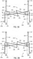
FIGS. 3A and 3B are top plan views of the piston lock system ofFIG. 2 , shown in the unlocked and locked positions, respectively. -
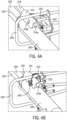
FIGS. 4A and 4B are isometric views of a portion of the piston lock system ofFIG. 2 , shown in the unlocked and locked positions, respectively. -
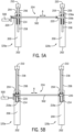
FIGS. 5A and 5B are top plan views of another piston lock system, shown in the unlocked and retracted position, and the extended and locked position, respectively. -
FIGS. 6A and 6B are top plan views of another piston lock system, shown in the unlocked and retracted position, and the extended and locked position, respectively. -
FIGS. 7A and 7B are top plan views of another piston lock system, shown in the unlocked and retracted position, and the extended and locked position, respectively. -
FIGS. 8A and 8B are side views of the piston lock system ofFIGS. 7A and 7B , shown in the unlocked and retracted position, and the extended and locked position, respectively. -
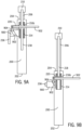
FIGS. 9A and 9B are top plan views of another piston lock system, shown in the unlocked and retracted position, and the extended and locked position, respectively. - In the figures, like reference numerals refer to the same or similar elements.
- Exemplary embodiments of the present invention provide piston lock systems which may be used in agricultural equipment (e.g., combines, windrowers, etc.), or in other environments. However, the invention is not limited to any particular application except as may be specifically recited in the claims.
- Referring to
FIG. 1 , an example of anagricultural vehicle 100, which in this case is an agricultural combine, is schematically illustrated. Thevehicle 100 includes achassis 102 that is supported for movement on the ground by wheels 104 (e.g., pneumatic tires or tracked wheels). Aheader assembly 106 is attached to thecombine 100 and configured to receive crop material and convey such material to a threshing and separatingsystem 108 located in or on thechassis 102. The threshing and separatingsystem 108 separates grain from the remaining crop material (also known as "material other than grain," "MoG," or "residue"). The separated grain is stored in ahopper 110, and the MoG is evacuated to the trailing path of thevehicle 100 by aspreader 112. - The
header assembly 106 comprises afeeder housing 114 and aheader 116. Thefeeder housing 114 is pivotally connected to thechassis 102 at ahorizontal pivot 118. One ormore actuators 120 are connected between thechassis 102 and thefeeder housing 114. Each actuator comprises a hydraulic cylinder and piston assembly with a piston lock system, such as described in more detail below. - The features described in relation to
FIG. 1 are generally conventional, except for the actuators, and particularly the piston lock system, and no further explanations of their structures or operations are necessary. - Referring now to
FIG. 2 , a first example of a piston lock system is shown and described in detail. In this case, the piston lock system is shown installed on afirst actuator 120a and asecond actuator 120b, but it will be appreciated that features of the piston lock system may be implemented on a single actuator. - Each
actuator 120 comprises acylinder 200 extending from a fixedcylinder end 202 to afree cylinder end 204, and apiston 206 extending through thefree cylinder end 204 from asliding piston end 208 to afree piston end 210. Thesliding piston end 208 is contained in thecylinder 200, and thefree piston end 210 is located outside thecylinder 200. Thepiston 206 is slidable relative to thecylinder 200 in a manner that is conventional in the art of hydraulic actuators. For example, a hydraulic system may include a one or morehydraulic ports 212 that are fluidly connected to the interior of the cylinder, and configured to convey pressurized hydraulic fluid to extend or retract thepiston 206 relative to thecylinder 200. Such hydraulic systems are conventional, and need not be described in further detail herein. - At least one
rod receiver 214 is fixed to eachcylinder 200. In the shown example, eachcylinder 200 has tworod receivers 214 located on opposite sides of thecylinder 200. Eachrod receiver 214 comprises a housing-like structure having alongitudinal passage 216a that is oriented in parallel with the sliding direction of thepiston 206, and alateral passage 216b oriented at an angle to the sliding direction of thepiston 206. Examples of thelongitudinal passage 216a andlateral passage 216b are shown inFIG. 5A . Thelateral passage 216b includes a wall facing towards thefree cylinder end 204, which serves as a surface that bears loads to lock thepiston 206 in position. to this end, thelateral passage 216b preferably extends perpendicular to the sliding direction of thepiston 206, but this is not strictly required. - At least one
rod 218 is attached to eachpiston 206. In the shown example, there are tworods 218 attached to opposite sides of eachpiston 206. Eachrod 218 extends, parallel to thepiston 206, from a fixed rod end that is secured to thefree piston end 210, to a free rod end that extends into arespective rod receiver 214. The fixed rod end, and thus theentire rod 218, is configured to move in unison with thefree piston end 210. For example, therod 218 may be attached by a bolt, adhesives or welding to a boss extending from a side of thefree piston end 210. - As shown, for example in the embodiment shown in
FIGS. 5A and 5B , thepistons 206 androds 218 are telescopically movable relative to therespective cylinders 200 androd receivers 214 between a retracted position (FIG. 5A ) and an extended position (FIG. 5B ). The free piston ends 210 and fixed rod ends are farther from the free cylinder ends 204 in the extended position than in the retracted position. As noted above, suitable hydraulic controls may be used to extend and retract thepistons 206 relative to thecylinders 200. - At least one
lock pin 220 is mounted to eachcylinder 200. For example, alock pin 220 may be slidingly connected to eachrod receiver 214. The lock pins 220 are movable between an unlocked position (FIG. 3A ) in which the lock pins 220 do not intersect a path of therespective rod 218, and a locked position (FIG. 3B ) in which thelock pin 220 intersects the path of therespective rod 218. In the locked position, eachlock pin 220 is captured between the free end ofrod 218 and a wall of the lateral passage 216, and thus prevents therod 218 andpiston 206 from moving from the extended position to the retracted position. - While it is envisioned that the lock pins 220 may be separately moved between their respective locked and unlocked positions, it is more preferred to provide a mechanism to simultaneously operate all of the lock pins 220. This provides greater assurance that all of the lock pins 220 are properly positioned to prevent the
pistons 206 from inadvertently retracting from the extended position towards the retracted position. In the example ofFIGS. 2-4B . The lock pins 220 associated with eachcylinder 200 are connected to each other by aplate 222, to thereby cause them to move in unison. In addition, the lock pins 220 from oneactuator 120a are connected to the lock pins 220 of theother actuator 120b by acontrol link 224 that is configured to simultaneously move the lock pins 220 of thefirst actuator 120a with the lock pins 220 of thesecond actuator 120b between their respective locked and unlocked positions - In this example, the
control link 224 comprises acentral transfer link 226, a first connectinglink 228 joining the lock pins 220 of thefirst actuator 120a to thetransfer link 226, and a second connectinglink 230 joining the lock pins 220 of thesecond actuator 120b to the transfer link. The transfer link is pivotally mounted at atransfer link pivot 232. Thetransfer link pivot 232 is fixed to move in unison with theactuators transfer link 226 throughout the range of motion of the entire assembly. For example, thetransfer link pivot 232 may be secured to one or bothcylinders 200 by one or more braces, such as the illustrated cross braces 234. The cross braces 234 may be secured to thecylinders 200 by a direct connection or by connection to therod receivers 214. - When installed on a
vehicle 100, thecylinders 200 are configured to be coplanar or parallel throughout their respective ranges of motion. When coplanar, the fixed cylinder ends 202 and free piston ends 210 all lie in a common plane. When parallel, the fixed cylinder ends 202 and free piston ends 210 all lie in a common plane, and thecylinders 200 andpistons 206 are parallel within the common plane. In either case, some variation may occur during regular use due to differential loading and slight differences in hydraulic system operations. In either case, thecylinders 200 define a plane between them, and thetransfer link pivot 232 may be oriented with a rotation axis that extends orthogonal to the plane defined between the twocylinders 200. Thetransfer link pivot 232 may comprise a pin or the like that extends orthogonal to this plane. As will be clear from the following explanation of the operation of thecontrol link 224, this orthogonal orientation allows thecontrol link 224 to remain generally within the plane throughout the range of motion, leading to a more compact system. - The first connecting
link 228 and second connectinglink 230 are attached by pivots to opposite ends of thetransfer link 226, with thetransfer link pivot 232 being approximately midway between the connections to the two connectinglinks link 228 causes a corresponding opposite movement of the other connectinglink 230. Each connectinglink lock pin plate 222. Thus, movement of alock pin 220 on oneactuator 120a causes a simultaneous and opposite movement of aconnected lock pin 220 on theother actuator 120b. - The control link 224 may be operated using any suitable mechanism. For example, in
FIGS. 2-4B , ahandle 236 may be connected to the lock pins 220 orlock pin plate 222 of oneactuator 120a. Thehandle 236 is positioned and configured for manual operation by a technician. For example, thehandle 236 may comprise an elongated bar that is located on a side of thecylinder 200 opposite thecontrol link 224, to allow operation without having to enter the space between the twoactuators handle 236 also may include a service lock 238 (FIG. 4B ) to prevent inadvertent operation to move the lock pins 220 from the locked position to the unlocked position. Theservice lock 238 may comprise, for example, a pin that is insertable into a hole in the end of thelock pin 220, to prevent withdrawal from the locked position. The control link 224 also may be operated by a remote system, such as described below. Other alternatives and variations will be apparent to persons of ordinary skill in the art in view of the present disclosure. - Referring now to
FIGS. 3A-4B , the operation of the lock pins 220 is shown in more detail.FIGS. 3A and4A show the lock pins 220 in the unlocked position, andFIGS. 3B and4B show the lock pins 220 in the locked position. In this case, thecontrol link 224 is located entirely in a space between the twocylinders 200. During operation, the lock pins 220 of each cylinder move in opposite directions. Specifically, the lock pins 220 for thefirst actuator 120a move away from thesecond actuator 120b when moving from the unlocked position to the locked position, and the lock pins 220 for thesecond actuator 120b move away from thefirst actuator 120b when moving from the unlocked position to the locked position. The reverse operation moves the lock pins 220 to their unlocked positions. -
FIGS. 5A and 5B show an alternative piston lock system. In this case, the mechanisms are generally the same as in the embodiment ofFIGS. 2-4B , so this description addresses the differences between the embodiments. - First, the
handle 236 is replaced by apowered actuator 500. Theactuator 500 may be any suitable powered motion device, such as a pneumatic, hydraulic or electric telescoping element (e.g., a piston/cylinder assembly). Theactuator 500 can be operated remotely, either by an automated control system or by a user's direct input. - Second, the
control link 224 is provided in the form of apushrod 502 that extends to connect the lock pins 220 of thefirst actuator 120a with the lock pins 220 of thesecond actuator 120b. The lock pins 220 are slidably mounted to therod receivers 214, and thepushrod 502 is configured to move along an axis A extending between thecylinders 200 of the first andsecond actuators cylinders 200, but this is not strictly required. Thepushrod 502 may be rigidly connected to the lock pins 220, or connected by pivots or other flexible connectors to allow some relative displacement between the twoactuators pushrod 502 also may be connected directly to the lock pins 220, or to a structure that holds the lock pins 220, such as theplate 222 described above. - In use, the
actuator 500 drives one end of thepushrod 502 or one set of lock pins 220, and such motion is transferred to the other lock pins by thepushrod 502. In this example, the lock pins 220 all move in the same direction between their respective locked and unlocked positions. For example, first lock pin or pins 220 of thefirst actuator 120a move towards thesecond actuator 120b when moving from the unlocked position to the locked position, and the lock pin or pins 220 of thesecond actuator 120b move away from thefirst actuator 120a when moving from the unlocked position to the locked position. This arrangement has the benefit of potentially being simpler and less prone to service requirements as the embodiment ofFIGS. 2-4B , but also may be less compact due to parts of thecontrol link 224 being outside the space between theactuators handle 236 and/or apowered actuator 500. -
FIGS. 6A and 6B show another alternative embodiment. In this case, the sliding lock pins 220 of the previous embodiment are replaced by rotating lock pins 220. The rotating lock pins 220 are connected by anarm 600 and apivot 602 to thecylinder 200 and/orrod receiver 214. In this case, thecontrol link 224 is apushrod 502 that is operated by ahandle 236. If necessary, thepushrod 502 may be connected to thearm 600 by anotherpivot 604, to allow thepushrod 502 to remain oriented towards alock pin 220 on an adjacent actuator (not shown inFIGS. 6A and 6B ). In use, thepushrod 236 is moved to rotate thearm 600 and place thelock pin 220 into thelateral passage 216b. - In other embodiments, different pivoting or moving connections may be provided between the lock pins 220 and the
rod receiver 214, and other control links may be used. -
FIGS. 7A-8B show another embodiment. In this case, thecontrol link 224 comprises anaxle 700 extending from thelock pin 220 of thefirst actuator 120a to the lock pin of a second actuator (not shown). Theaxle 700 is pivotally mounted to the cylinders 200 (either directly or via therod receiver 214 or other structure), and configured to rotate about an axis A extending between theactuators axle 700 by one or more offsetarms 702, and thus move with theaxle 700 through an arcuate path as theaxle 700 rotates. Ahandle 236 or other control is provided to rotate theaxle 700. - As best shown in
FIGS. 8A and 8B , rotating theaxle 700, such as by operating ahandle 236 or other control, moves the lock pins 220 between an unlocked position (FIGS. 7A and 8A ) and a locked position (FIGS. 7B and 8B ). As shown inFIG. 7B , in the locked position, thelock pin 220 is positioned between therod 218 and aninner face 704 of therod receiver 214, and preferably in contact with both theinner face 704 and therod 218 to provide a direct load-bearing path from the rod to therod receiver 214. If necessary, thelock pin 220 may be connected to theaxle 700 or offsetarms 702 by a lost-motion mechanism (e.g., a pin that fits into a slot or oversized hole), to allow thelock pin 220 to move slightly to make contact with thesurface 704. - The foregoing arrangement of direct contact and a direct load-bearing path is also preferred for the other embodiments described herein to simplify the structural requirements to support the
piston 206 in the extended position. In each case, some lost motion (i.e., limited free movement between the parts) or flex may be designed into the lock pins 220 and related parts to ensure proper contact under various operating conditions and to account for potential tolerance stacking issues. -
FIGS. 9A and 9B show a further embodiment, in which acam 900 is used to move thelock pin 220 between the locked and unlocked positions. Thecam 900 is rotatably mounted to thecylinder 200 orrod receiver 214, and includes ahelical cam track 902. Acam follower 904, such as a pin, is attached to the lock pin 220 (or to aplate 222 or other comparable structure), and positioned within the cam track. Ahandle 236 is provided to rotate thecam 900. Rotating thecam 900 causes thecam track 902 to drive thecam follower 904, thus moving thelock pin 220 between the locked and unlocked positions. - In the shown embodiment, a
pushrod 502 is attached to thelock pin 220 to transfer motion to another lock pin on an adjacent actuator, but this is not strictly required. In other examples, there may not be another actuator, or the other actuator or actuators may have separate lock pin controls. In still another example, each actuator may have itsown cam 900 or cams, and the cams of the actuators may be joined by an axle such as theaxle 700 of the embodiment ofFIGS. 7A-8B . In this case, rotating theaxle 700 would rotate bothcams 900 in unison, and eachcam 900 would drive itsrespective lock pin 220 between the locked and unlocked positions. Other alternatives and variations will be apparent to persons of ordinary skill in the art in view of the present disclosure. - It will be appreciated that embodiments such as described herein can be used in various locations on agricultural vehicles and equipment, particularly those having multiple actuators. For example, the
actuators vehicle chassis 102, and the free rod ends connected to afeeder housing 114, or vice-versa. Such connections can be made in the manner of a conventional actuator, and thus embodiments may be provided as a retrofit assembly for an existingvehicle 100. - It is expected that embodiments will provide easier and more efficient options to lock pistons of actuators in the extended positions, and thus can improve serviceability and safety of such devices. Furthermore, embodiments having the capability to simultaneously operate lock pins on multiple actuators can have a significant benefit in cases in which locking a single actuator is not sufficient to adequately secure a load. For example, modern agricultural combine headers having two actuators can weigh too much to be reliably held by a single one of its actuators, in which case the ability to simultaneously lock both actuators is particularly desirable.
- The present disclosure describes a number of inventive features and/or combinations of features that may be used alone or in combination with each other or in combination with other technologies. The embodiments described herein are all exemplary, and are not intended to limit the scope of the claims. It will be appreciated that various aspects of the embodiments described herein may be provided as component parts or as subassemblies. It will also be appreciated that the inventions described herein can be modified and adapted in various ways, and all such modifications and adaptations are intended to be included in the scope of this disclosure and the appended claims.
Claims (15)
- A piston lock system comprising:a first cylinder (200) extending from a first fixed cylinder end (202) to a first free cylinder end (204);a first rod receiver (214) fixed to the first cylinder;a first piston (206) extending through the first free cylinder end (204) from a first sliding piston end (208) contained in the first cylinder (200) to a first free piston end (210) located outside the first cylinder (200);a first rod (218) extending, parallel to the first piston (206), from a first fixed rod end secured to move with the first free piston end (210) to a first sliding rod end located within the first rod receiver (214), wherein the first piston (206) and first rod (218) are movable relative to the first cylinder (200) and first rod receiver (214) between a first retracted position and a first extended position, with the first free piston end (210) and first fixed rod end being farther from the first free cylinder end (204) in the first extended position than in the first retracted position; anda first lock pin (220) mounted to the first rod receiver (214) and movable between a first unlocked position in which the first lock pin (220) does not intersect a path of the first rod (218), and a first locked position in which the first lock pin (220) intersects the path of the first rod (218) and prevents the first rod (218) and first piston (206) from moving from the first extended position to the first retracted position.
- The piston lock system of claim 1, further comprising:a second cylinder (200) extending from a second fixed cylinder end (202) to a second free cylinder end (204);a second rod receiver (214) fixed to the second cylinder (200);a second piston (206) extending through the second free cylinder (204) end from a second sliding piston end (208) contained in the second cylinder (200) to a second free piston end (210) located outside the second cylinder (200);a second rod (218) extending, parallel to the second piston (206), from a second fixed rod end secured to move with the second free piston end (210) to a second sliding rod end located within the second rod receiver (214), wherein the second piston (206) and second rod (218) are movable relative to the second cylinder (200) and second rod receiver (214) between a second retracted position and a second extended position, with the second free piston end (210) and second fixed rod end being farther from the second free cylinder end (204) in the second extended position than in the second retracted position; anda second lock pin (220) mounted to the second rod receiver (214) and movable between a second unlocked position in which second lock pin (220) does not intersect a path of the second rod (218), and a second locked position in which the second lock pin (220) intersects the path of the second rod (218) and prevents the second rod (218) and second piston (206) from moving from the second extended position to the second retracted position.
- The piston lock system of claim 2, further comprising a control link (224) operatively connecting the first lock pin (220) to the second lock pin (220) and configured to simultaneously move the first lock pin (220) between the first locked position and the first unlocked position, and the second lock pin (220) between the second locked position and the second unlocked position.
- The piston lock system of claim 3, wherein the control link (224) comprises:a transfer link pivot (232) mounted between the first cylinder (200) and the second cylinder (200);a transfer link (226) pivotally mounted to the transfer link pivot (232) to rotate about an axis orthogonal to a plane defined between the first cylinder (200) and the second cylinder (200);a first connecting link (228) pivotally connected at a respective first end to the first lock pin (220) and pivotally connected at a respective second end to a first end of the transfer link (226); anda second connecting link (230) pivotally connected at a respective first end to the second lock pin (220) and pivotally connected at a respective second end to a second end of the transfer link (226), with the transfer link pivot (232) located between the first end of the transfer link (226) and the second end of the transfer link (226).
- The piston lock system of claim 3, wherein:the control link (224) is located entirely in a space between the first cylinder (200) and the second cylinder (200);the first lock pin (220) is configured to move away from the second cylinder (200) when moving from the first unlocked position to the first locked position; andthe second lock pin (220) is configured to move away from the first cylinder (200) when moving from the second unlocked position to the second locked position.
- The piston lock system of claim 5, further comprising a handle (236) operatively connected to the first lock pin (220), wherein the handle (236) preferably is located on a side of the first cylinder (200) opposite the control link (224).
- The piston lock system of claim 3, wherein the control link (224) comprises a pushrod (502) extending from the first lock pin (220) to the second lock pin (220) and configured to move along an axis extending between the first cylinder (200) and the second cylinder (200).
- The piston lock system of claim 7, wherein:the first lock pin (220) is configured to move towards the second cylinder (200) when moving from the first unlocked position to the first locked position; andthe second lock pin (220) is configured to move away from the first cylinder (200) when moving from the second unlocked position to the second locked position.
- The piston lock system of claim 3, wherein the control link (224) comprises an axle (700) extending from the first lock pin (220) to the second lock pin (220) and pivotally mounted to the first cylinder (200) and the second cylinder (200) to rotate about an axis extending from the first cylinder (200) to the second cylinder (200).
- The piston lock system of claim 9, wherein the first lock pin (220) and the second lock pin (220) are rigidly connected to move with the axle (700).
- The piston lock system of claim 1, further comprising a cam (900) operatively connected to the first lock pin (220) and configured to move the first lock pin (220) between the first locked position and the first unlocked position.
- The piston lock system of claim 1, wherein:the first rod receiver (214) comprises a pair of first rod receivers (214) located on opposite sides of the first cylinder (200);the first rod (218) comprises a pair of first rods (218) located on opposite sides of the first piston(206); andand the first lock pin (220) comprises a pair of first lock pins (220) located on opposite sides of the first cylinder (200).
- The piston lock system of claim 2, further comprising a hydraulic system (212) configured to simultaneously move the first piston (206) from the first retracted position to the first extended position, and the second piston (206) from the second retracted position to the second extended position.
- The piston lock system of claim 13, wherein:the first fixed cylinder end (202) and the second fixed cylinder end (202) are operatively connected to one of a vehicle chassis (102) and a feeder housing (114); andthe first free piston end (210) and the second free piston end (210) are operatively connected to the other of the vehicle chassis (102) and the feeder housing (114).
- An agricultural combine (100) comprising:a chassis (102) configured for movement on a surface;a feeder housing (114) pivotally connected to the chassis (102); anda piston lock system according to any of the preceding claims.
Applications Claiming Priority (1)
| Application Number | Priority Date | Filing Date | Title |
|---|---|---|---|
| US17/520,223 US12279557B2 (en) | 2021-11-05 | 2021-11-05 | Piston lock system for agricultural equipment |
Publications (1)
| Publication Number | Publication Date |
|---|---|
| EP4176703A1 true EP4176703A1 (en) | 2023-05-10 |
Family
ID=84330189
Family Applications (1)
| Application Number | Title | Priority Date | Filing Date |
|---|---|---|---|
| EP22205794.5A Pending EP4176703A1 (en) | 2021-11-05 | 2022-11-07 | Piston lock system for agricultural equipment |
Country Status (2)
| Country | Link |
|---|---|
| US (1) | US12279557B2 (en) |
| EP (1) | EP4176703A1 (en) |
Citations (11)
| Publication number | Priority date | Publication date | Assignee | Title |
|---|---|---|---|---|
| US2932282A (en) * | 1957-07-08 | 1960-04-12 | Roe L Mckinley | Fluid actuated systems for operating and locking control elements |
| DE2706442A1 (en) * | 1977-02-16 | 1978-08-17 | Ruthmann Maschf Anton | CYLINDER-PISTON UNIT WITH LOCKABLE PISTON |
| US4388038A (en) * | 1981-04-22 | 1983-06-14 | Sperry Corporation | Automatic locking pin retraction mechanism |
| US4529215A (en) | 1983-02-03 | 1985-07-16 | Tci, Inc. | Hydraulic cylinder safety lock |
| JPH04137979U (en) * | 1991-06-18 | 1992-12-22 | 三輪精機株式会社 | cab tilt device |
| EP1473467A1 (en) * | 2003-04-11 | 2004-11-03 | Ian Hill | Locking mechanism for a linear actuator |
| JP2006168851A (en) * | 2004-12-13 | 2006-06-29 | Hitachi Constr Mach Co Ltd | Working machine |
| EP2740346A2 (en) * | 2012-12-06 | 2014-06-11 | CNH Industrial Belgium nv | Automatically engaging and disengaging header lock assembly |
| EP2367713B1 (en) * | 2008-12-19 | 2014-08-06 | Caterpillar Commercial S.A.R.L. | Lock apparatus for variable gauge undercarriage |
| CN104632781A (en) * | 2014-12-26 | 2015-05-20 | 徐州重型机械有限公司 | Expanding oil cylinder, super-lifting device, crane and method |
| CN213870528U (en) * | 2020-12-02 | 2021-08-03 | 萨润液压(江苏)有限公司 | Manual self-locking oil cylinder |
Family Cites Families (7)
| Publication number | Priority date | Publication date | Assignee | Title |
|---|---|---|---|---|
| US3730362A (en) | 1971-09-09 | 1973-05-01 | Sperry Rand Corp | Anti-lowering device for a loader boom |
| US3995761A (en) | 1975-09-04 | 1976-12-07 | Sperry Rand Corporation | Anti-lowering device for a boom loader |
| DE7539577U (en) * | 1975-12-12 | 1976-05-13 | Stabilus Gmbh, 5400 Koblenz | GAS SPRING WITH MECHANICAL LOCKING |
| US4811983A (en) * | 1986-11-17 | 1989-03-14 | Clark Equipment Company | Gas spring with latching stop mechanism for use on skid-steer loaders |
| DE102004042126A1 (en) | 2004-08-30 | 2006-03-02 | Claas Selbstfahrende Erntemaschinen Gmbh | Safety prop for hydraulic jack of harvester, has base designed as channel section, and exchangeable head end plate that is connected reciprocally with front side of channel section using bolt connection |
| US7905088B2 (en) * | 2006-11-14 | 2011-03-15 | Incova Technologies, Inc. | Energy recovery and reuse techniques for a hydraulic system |
| EP3679783B1 (en) | 2019-01-09 | 2022-03-09 | CNH Industrial Belgium N.V. | Cylinder lock system |
-
2021
- 2021-11-05 US US17/520,223 patent/US12279557B2/en active Active
-
2022
- 2022-11-07 EP EP22205794.5A patent/EP4176703A1/en active Pending
Patent Citations (11)
| Publication number | Priority date | Publication date | Assignee | Title |
|---|---|---|---|---|
| US2932282A (en) * | 1957-07-08 | 1960-04-12 | Roe L Mckinley | Fluid actuated systems for operating and locking control elements |
| DE2706442A1 (en) * | 1977-02-16 | 1978-08-17 | Ruthmann Maschf Anton | CYLINDER-PISTON UNIT WITH LOCKABLE PISTON |
| US4388038A (en) * | 1981-04-22 | 1983-06-14 | Sperry Corporation | Automatic locking pin retraction mechanism |
| US4529215A (en) | 1983-02-03 | 1985-07-16 | Tci, Inc. | Hydraulic cylinder safety lock |
| JPH04137979U (en) * | 1991-06-18 | 1992-12-22 | 三輪精機株式会社 | cab tilt device |
| EP1473467A1 (en) * | 2003-04-11 | 2004-11-03 | Ian Hill | Locking mechanism for a linear actuator |
| JP2006168851A (en) * | 2004-12-13 | 2006-06-29 | Hitachi Constr Mach Co Ltd | Working machine |
| EP2367713B1 (en) * | 2008-12-19 | 2014-08-06 | Caterpillar Commercial S.A.R.L. | Lock apparatus for variable gauge undercarriage |
| EP2740346A2 (en) * | 2012-12-06 | 2014-06-11 | CNH Industrial Belgium nv | Automatically engaging and disengaging header lock assembly |
| CN104632781A (en) * | 2014-12-26 | 2015-05-20 | 徐州重型机械有限公司 | Expanding oil cylinder, super-lifting device, crane and method |
| CN213870528U (en) * | 2020-12-02 | 2021-08-03 | 萨润液压(江苏)有限公司 | Manual self-locking oil cylinder |
Also Published As
| Publication number | Publication date |
|---|---|
| US12279557B2 (en) | 2025-04-22 |
| US20230146262A1 (en) | 2023-05-11 |
Similar Documents
| Publication | Publication Date | Title |
|---|---|---|
| US8499538B2 (en) | Adjustable and foldable V-shaped hay rake | |
| US20090101369A1 (en) | Bifold transport lock | |
| EP2857592B1 (en) | Hydraulic system for the front loader assembly of a vehicle | |
| US9290265B2 (en) | Main landing gear compact axle steering | |
| US10994843B2 (en) | Aircraft cargo pallet lock assemblies | |
| EP3881668B1 (en) | Pivoting apparatus for row head | |
| US10433482B2 (en) | Integrated lift and frame lock for a folding corn head row separator | |
| WO2011163631A1 (en) | Planter with four bar linkage | |
| EP2989881B1 (en) | Header latch mechanism for agricultural vehicle | |
| US12279557B2 (en) | Piston lock system for agricultural equipment | |
| US8899517B2 (en) | Landing gear | |
| EP2857593B1 (en) | Front loader assembly | |
| DE102010028687A1 (en) | Harvesting header i.e. maize picker, for harvesting and positioning crop, has retainer extending in transporting position in forward direction and in operating position transverse to forward direction | |
| US11473600B1 (en) | Piston lock system for agricultural equipment | |
| EP3571908B1 (en) | Folding hitch | |
| US20180343786A1 (en) | Lockable joint for a toolbar | |
| CN107021227B (en) | Telescopic self-aligning aircraft stabilizer strut assembly and aircraft comprising same | |
| US11840821B2 (en) | Removable tool assembly for construction machines | |
| US11716922B2 (en) | Agricultural toolbar with wing flex lock | |
| BR102022022215A2 (en) | PISTON LOCKING SYSTEM FOR AGRICULTURAL EQUIPMENT | |
| EP4535979A1 (en) | Implement operating apparatus and methods for same | |
| CA2722482C (en) | An articulating and locking mechanism for a chassis of an agricultural implement, and an agricultural implement | |
| DK177486B1 (en) | hinges | |
| CA3124326A1 (en) | Folding harvester with crop divider lift and frame lock | |
| EP1054804B1 (en) | Aircraft undercarriage locking system |
Legal Events
| Date | Code | Title | Description |
|---|---|---|---|
| PUAI | Public reference made under article 153(3) epc to a published international application that has entered the european phase |
Free format text: ORIGINAL CODE: 0009012 |
|
| STAA | Information on the status of an ep patent application or granted ep patent |
Free format text: STATUS: THE APPLICATION HAS BEEN PUBLISHED |
|
| AK | Designated contracting states |
Kind code of ref document: A1 Designated state(s): AL AT BE BG CH CY CZ DE DK EE ES FI FR GB GR HR HU IE IS IT LI LT LU LV MC ME MK MT NL NO PL PT RO RS SE SI SK SM TR |
|
| STAA | Information on the status of an ep patent application or granted ep patent |
Free format text: STATUS: REQUEST FOR EXAMINATION WAS MADE |
|
| 17P | Request for examination filed |
Effective date: 20231110 |
|
| RBV | Designated contracting states (corrected) |
Designated state(s): AL AT BE BG CH CY CZ DE DK EE ES FI FR GB GR HR HU IE IS IT LI LT LU LV MC ME MK MT NL NO PL PT RO RS SE SI SK SM TR |
|
| STAA | Information on the status of an ep patent application or granted ep patent |
Free format text: STATUS: EXAMINATION IS IN PROGRESS |
|
| 17Q | First examination report despatched |
Effective date: 20250124 |