EP4176340B1 - Tactile arrangement for display device - Google Patents
Tactile arrangement for display device Download PDFInfo
- Publication number
- EP4176340B1 EP4176340B1 EP20948061.5A EP20948061A EP4176340B1 EP 4176340 B1 EP4176340 B1 EP 4176340B1 EP 20948061 A EP20948061 A EP 20948061A EP 4176340 B1 EP4176340 B1 EP 4176340B1
- Authority
- EP
- European Patent Office
- Prior art keywords
- actuator
- display device
- signal generating
- generating element
- arrangement
- Prior art date
- Legal status (The legal status is an assumption and is not a legal conclusion. Google has not performed a legal analysis and makes no representation as to the accuracy of the status listed.)
- Active
Links
Images


Classifications
-
- G—PHYSICS
- G06—COMPUTING OR CALCULATING; COUNTING
- G06F—ELECTRIC DIGITAL DATA PROCESSING
- G06F3/00—Input arrangements for transferring data to be processed into a form capable of being handled by the computer; Output arrangements for transferring data from processing unit to output unit, e.g. interface arrangements
- G06F3/01—Input arrangements or combined input and output arrangements for interaction between user and computer
- G06F3/016—Input arrangements with force or tactile feedback as computer generated output to the user
Definitions
- the disclosure relates to a tactile arrangement for a display device, the arrangement comprising a haptic signal generating element and an actuator.
- Mobile electronic consumer products such as smartphones and wearable devices, smart garments, and their accessories, may generally include vibrators for generating tactile feedback such as conventional (warnings) and conditional cues (directional, numerical, rhythmic and so on).
- vibrators for generating tactile feedback
- conventional (warnings) and conditional cues directional, numerical, rhythmic and so on.
- smartphones and wrist wearable devices such as smart watches and trackers
- known high-fidelity tactile imaging is not yet accurate enough to meet user demands.
- the technical problems include signal dissipation and distortion when vibrations are transmitted to the hand through a rigid non-planar multilayered medium, inappropriate interference, and overlapping with ambient noise.
- Other factors are related to human perception that can affect fingertip sensation, signal detection, and distinguishability.
- a tactile display device in which vibration is applied to the fingernail side, not to the pad side of the user's finger, such that a virtual undulating sensation can be superimposed onto the real-world sensations obtained during a scanning action of the finger.
- the device is based on the phenomenon that when a vibration is applied while the finger is scanning an object, a perception of undulation rather than of vibration is produced.
- This method of induced tactile stimulation is able to modify the pressure produced on the pad side of the finger but requires active scanning operation to perceive the dynamics of the modified original parameters specified by the local finger pressure on the real surface.
- the method also requires an additional gadget attached to the fingernail.
- US 2011/0285637 A1 relates to an apparatus for a user interface of an electronic device, the apparatus comprising a textured surface having a predetermined roughness, the textured surface configured to produce a first predefined vibration in the skin of a user of the apparatus on physical interaction with the skin of the user, wherein the roughness of the textured surface is configured such that the first predefined vibration produced by the physical interaction has a frequency and/or amplitude which is detectable by a specific mechanical receptor in the skin of the user.
- the apparatus may comprise a capacitive element to generate a second predefined vibration in the skin of the user independently of the textured surface.
- US 2019/0391653 A1 discloses a tactile sense presentation apparatus that includes a movable body, an actuator unit, and a signal generation unit.
- the actuator unit is connected to the movable body.
- the signal generation unit is configured to supply a driving signal to the actuator unit, the driving signal generating a vibration on the actuator unit.
- a tactile arrangement for a display device comprising a structure extending in a main plane and comprising a haptic signal generating element and a modulating signal generating element superimposed onto the haptic feedback element, at least one first actuator configured to displace the structure along an actuation axis perpendicular to the main plane by generating at least a first transverse wave, the first transverse wave propagating, from the first actuator, along a main propagation axis in the main plane, and at least one second actuator configured to displace the structure in an actuation plane perpendicular to the main propagation axis by generating a tangential wave, the tangential wave propagating, from the second actuator, in auxiliary propagation directions extending tangentially to the first transverse wave.
- the tangential wave is superimposed onto the first transverse wave such that the tangential wave modulates at least one of a frequency and amplitude of the first transverse wave.
- the tactile perception of the user is enhanced.
- the local perception of constructive wave interference vibration signals can be enhanced by superimposed modulating signals. This helps to achieve high fidelity imaging in two-dimensional and three-dimensional haptic space without requiring unnecessarily constrictive demands to signals, propagation media, and available haptic actuator technology.
- the haptic signal generating element and modulating signal generating element as propagation medium for vibration signals, i.e.
- the structure is layered such that the haptic signal generating element and the modulating signal generating element are arranged in parallel, abutting layers, allowing the haptic signal generating element and the modulating signal generating element to be integrated and the modulating signal generating element to be supported and carried by the haptic signal generating element.
- the modulating signal generating element has increased surface friction compared to the haptic signal generating element. This allows further enhancement of the user's tactile perception of the superimposed waves.
- Such tactile stimulation is achieved by modulating the surface friction, i.e. enhancing the tactile contrast (the tactile signal-to-noise ratio) at a specific point.
- the modulating signal generating element has a textured surface, eliminating the need for active or transformable components.
- the propagation of the first transverse wave comprises movement, in steps along the main propagation axis, of a local interference maximum of the first transverse wave.
- the local interference maximum focuses the user's attention to that specific area of skin contact, and the relative trajectory of the local interference maximum, i.e. normal micro displacements, moving across the contact area can be distinguished more accurately by the user, due to the presence of superimposed tangential waves making the surrounding material, i.e. the modulating signal generating element of an electronic device or an accessory covering, stimulate the skin.
- the modulating signal generating element comprises a polymeric material or print, facilitating a durable and thin modulating signal generating element.
- the modulating signal generating element comprises a grid pattern, a step of the grid pattern complying with a displacement frequency generated by the second actuator.
- the second actuator is arranged at least partially adjacent the haptic signal generating element, allowing the actuation of the second actuator to be directly transmitted to the haptic signal generating element.
- a display device comprising a tactile arrangement according to the above, wherein at least one external surface of the display device comprises the structure of the arrangement, and the modulating signal generating element of the structure is configured to be in tactile contact with a user of the display device.
- Such an arrangement allows the tactile perception of the user to be enhanced significantly due to the arrangement being at least partially in direct contact with the user.
- the second actuator of the arrangement comprises a functional component of the display device, such as a battery.
- the arrangement comprises a plurality of first actuators, the plurality of first actuators being configured to displace the structure along the actuation axis by generating at least one transverse wave propagating along the main propagation axis in the main plane of the structure.
- transverse waves can be generated across different areas of the device, depending on which actuator is actuated.
- the plurality of first actuators are arranged in pairs and share main propagation axis, one actuator of the pair of first actuators generating a first transverse wave propagating in a first main propagation direction along the main propagation axis, the other actuator of the pair of first actuators generating a second transverse wave propagating in a second main propagation direction along the main propagation axis, such that the first transverse wave and the second transverse wave interfere constructively along the main propagation axis.
- each first actuator of the plurality of first actuators is configured to actuate with a predetermined delay with regards to actuation of the other first actuators of the plurality of first actuators, the delay being configured to create constructive wave interference between the first transverse wave and the second transverse wave.
- the display device comprises two pairs of first actuators, arranged such that each first actuator is arranged adjacent a corner of the display device, the first actuators of each pair being arranged at opposite corners such that the main propagation axis of one pair intersects the main propagation axis of the other pair.
- the first actuator is fixed to a stationary element of the display device, such as an internal chassis. This allows the actuator to be securely fixed and displacement to be limited to the components of the tactile arrangement.
- the display device is one of a VR haptic headset, a wearable, a smartphone, a tablet, or a laptop.
- the tactile arrangement is arranged in a casing for an electronic device, a haptic garment, or steering wheel covering.
- Figs. 1 and 3a-3b show a display device 2 comprising a tactile arrangement 1, described in more detail below.
- At least one external surface of the display device 2 comprises a structure 3 of the arrangement 1, and one part of the structure, i.e. a modulating signal generating element 5, is configured to be in tactile contact with the user of the display device 2, as indicated in Fig. 2 .
- the external surface is preferably comprised in a side portion and/or a back portion of the housing or cover 8 of the display device 2.
- the display device is a tactile display device 2, such as a VR haptic headset, a wearable, a smartphone, a tablet, or a laptop.
- the tactile arrangement 1 may be arranged not in a display device but in a casing for any electronic device, a haptic garment, or steering wheel covering.
- the first actuator 6 may be a one-dimensional actuator, generating movements only along the actuation axis A1 as indicated by the arrow in Fig. 2 .
- the first actuator 6 may comprise a piezoelectric actuator or an electromagnetic actuator comprising electromechanical polymer-metal composite or alloy material, magnetorestricitive material, electroactive material, photoactive material, temperature active material, and/or magnetoactive material (not shown).
- the first actuator 6 may be fixed to a stationary element of the display device 2, such as an internal chassis 9, as indicated in Fig. 3b .
- At least one second actuator 7 is provided and configured to displace the structure 3 in an actuation plane P2 which extends perpendicular to the main propagation axis A2, as shown in Figs. 2 and 3b .
- the second actuator 7 generates a modulating signal in the form of a tangential wave.
- the tangential wave propagates, from the second actuator 7, in auxiliary propagation directions extending tangentially to the first transverse wave, as indicated by intersecting arrows in Figs. 1 and 3a .
- the second actuator 7 may be a two-dimensional actuator, generating movements in actuation plane P2 as indicated by the two parallel arrows in Fig. 1 or 3a .
- the second actuator 7 may be arranged at least partially adjacent the haptic signal generating element 4.
- the second actuator 7 may be enclosed within at least a part of the haptic signal generating element 4, as shown in Fig. 3b .
- the second actuator 7 may be arranged at some distance from the haptic signal generating element 4, additional components being arranged between the second actuator 7 and the haptic signal generating element 4 such that the additional components transfer the vibrations from the second actuator 7 such that the tangential wave can still be generated by these vibrations.
- the second actuator 7 may comprise a functional component of the display device 2, such as a battery.
- the above-mentioned battery i.e. energy storage, may be adapted for supplying electric charge to drive the first actuator 6 and/or the second actuator 7.
- the second actuator 7 may be multifunctional having a plurality of functional actuation modes.
- a first functional actuation mode may comprise generating mechanical vibrations, also referred to as haptic signal generating mode.
- a second functional actuation mode may comprise generating electric charge by means of mechanical vibrations of the second actuator 7, the vibrations generating electric charge which is stored in the battery, also referred to as energy harvesting mode.
- the vibrations may be generated at frequencies below 30Hz, preferably below 20 Hz.
- the third functional actuation mode may comprise generating electric charge by means of a magnetic energy transmitter(not shown), the electric charge being stored in the battery, also referred to as wireless charging mode.
- the tangential wave is superimposed onto the first transverse wave such that the tangential wave modulates at least one of a frequency and amplitude of the first transverse wave, which enhances the tactile perception of the user.
- the propagation of the first transverse wave may comprise movement in steps, along the main propagation axis A2, of a local interference maximum of the first transverse wave.
- An instantaneous local interference maximum is indicated in Figs. 1 and 3a by a circular marking on the main propagation axis A2.
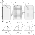
- the modulating signal generating element 5 may comprise grid patterns, as shown in Figs 4c to 4f.
- Figs. 4c-4d illustrate a redundant grid pattern which can cause extra noise for users having high sensitivity to vibrations.
- Figs. 4e-4f illustrate an optimized grid pattern which positively impacts and enhances perception of the local interference maximum moving across the actuation plane P2 in any direction.
- One actuator of the pair of first actuators 6 may generate a first transverse wave propagating in a first main propagation direction D 1 along the main propagation axis A2, while the other actuator of the pair of first actuators 6 may generate a second transverse wave propagating in a second main propagation direction D2 along the main propagation axis A2, as shown in Fig. 3a . This allows the first transverse wave and the second transverse wave to interfere constructively along the main propagation axis A2.
- each first actuator of the plurality of first actuators 6 may be configured to actuate with a predetermined delay with regards to the time and/or phase of actuation of the other first actuators of the plurality of first actuators 6.
- the delay is configured to create constructive wave interference between the first transverse wave and the second transverse wave.
Landscapes
- Engineering & Computer Science (AREA)
- General Engineering & Computer Science (AREA)
- Theoretical Computer Science (AREA)
- Human Computer Interaction (AREA)
- Physics & Mathematics (AREA)
- General Physics & Mathematics (AREA)
- User Interface Of Digital Computer (AREA)
Description
- The disclosure relates to a tactile arrangement for a display device, the arrangement comprising a haptic signal generating element and an actuator.
- As computer miniaturization progresses, an increasing number of features are expected to be incorporated into ever smaller packages. Mobile electronic consumer products, such as smartphones and wearable devices, smart garments, and their accessories, may generally include vibrators for generating tactile feedback such as conventional (warnings) and conditional cues (directional, numerical, rhythmic and so on). For example, smartphones and wrist wearable devices (such as smart watches and trackers) have embedded vibrators for generating tactile feedback signals while being in contact with the user.
- In order to achieve high fidelity imaging in two-dimensional and three-dimensional haptic space, including in smartphones, a number of methods and techniques have been proposed. For example, there are ongoing attempts to identify materials and/or methods of producing materials that are capable of enhancing tactile perception locally in response to specific signals and parameters in the area of contact. However, enhancing tactile sensitivity will often lead to a lowering of the signal-to-noise ratio. Noise can mask both the perception of weak stimuli and the perception of strong stimuli.
- Furthermore, known experimental haptic techniques, based on a close-loop control, for high-fidelity signal localization involve significant difficulties and limitations in their practical implementations in small electronic devices.
- Also, known high-fidelity tactile imaging is not yet accurate enough to meet user demands. The technical problems include signal dissipation and distortion when vibrations are transmitted to the hand through a rigid non-planar multilayered medium, inappropriate interference, and overlapping with ambient noise. Other factors are related to human perception that can affect fingertip sensation, signal detection, and distinguishability.
- For example, there has been proposed a tactile display device in which vibration is applied to the fingernail side, not to the pad side of the user's finger, such that a virtual undulating sensation can be superimposed onto the real-world sensations obtained during a scanning action of the finger. The device is based on the phenomenon that when a vibration is applied while the finger is scanning an object, a perception of undulation rather than of vibration is produced. This method of induced tactile stimulation is able to modify the pressure produced on the pad side of the finger but requires active scanning operation to perceive the dynamics of the modified original parameters specified by the local finger pressure on the real surface. The method also requires an additional gadget attached to the fingernail.
- Furthermore, there has been experiments with sensorimotor enhancers using piezoelectric actuators for generating white-noise vibrations which are transmitted to tactile receptors around the finger pulp of the user. Low-pass filtered white-noise vibrations have a cutoff frequency of 300 Hz. However, the construction features of the actuator attachment as well as ambient vibrations impairs the transmissibility to the fingertip and the spectrum of stochastic resonance signals.
-
US 2011/0285637 A1 relates to an apparatus for a user interface of an electronic device, the apparatus comprising a textured surface having a predetermined roughness, the textured surface configured to produce a first predefined vibration in the skin of a user of the apparatus on physical interaction with the skin of the user, wherein the roughness of the textured surface is configured such that the first predefined vibration produced by the physical interaction has a frequency and/or amplitude which is detectable by a specific mechanical receptor in the skin of the user. In addition to the textured surface, the apparatus may comprise a capacitive element to generate a second predefined vibration in the skin of the user independently of the textured surface. The document "A Review of Surface Haptics: Enabling Tactile Effects on Touch Surfaces" by Cagatay Basdogan et al. describes technologies enabling tactile feedback on touch surfaces.US 2019/0391653 A1 discloses a tactile sense presentation apparatus that includes a movable body, an actuator unit, and a signal generation unit. The actuator unit is connected to the movable body. The signal generation unit is configured to supply a driving signal to the actuator unit, the driving signal generating a vibration on the actuator unit. - It is an object to provide an improved tactile arrangement for a display device. The foregoing and other objects are achieved by the features of the independent claims. Further implementation forms are apparent from the dependent claims, the description, and the figures.
- According to a first aspect, there is provided a tactile arrangement for a display device according to
claim 1, the arrangement comprising a structure extending in a main plane and comprising a haptic signal generating element and a modulating signal generating element superimposed onto the haptic feedback element, at least one first actuator configured to displace the structure along an actuation axis perpendicular to the main plane by generating at least a first transverse wave, the first transverse wave propagating, from the first actuator, along a main propagation axis in the main plane, and at least one second actuator configured to displace the structure in an actuation plane perpendicular to the main propagation axis by generating a tangential wave, the tangential wave propagating, from the second actuator, in auxiliary propagation directions extending tangentially to the first transverse wave. The tangential wave is superimposed onto the first transverse wave such that the tangential wave modulates at least one of a frequency and amplitude of the first transverse wave. - By superimposing a tangential wave onto the transverse wave, the tactile perception of the user is enhanced. The local perception of constructive wave interference vibration signals can be enhanced by superimposed modulating signals. This helps to achieve high fidelity imaging in two-dimensional and three-dimensional haptic space without requiring unnecessarily constrictive demands to signals, propagation media, and available haptic actuator technology. By separating the actuation from the tactile stimulation, using the haptic signal generating element and modulating signal generating element as propagation medium for vibration signals, i.e. transverse and tangential waves, to the point of user skin contact, and using the constructive interference of the signals, high-definition multi-point haptic feedback is achieved while minimizing the number of actuators, allowing extra free space and reduced energy consumption, increased signal control, and increased haptic signal transfer efficiency.
- The structure is layered such that the haptic signal generating element and the modulating signal generating element are arranged in parallel, abutting layers, allowing the haptic signal generating element and the modulating signal generating element to be integrated and the modulating signal generating element to be supported and carried by the haptic signal generating element.
- In a further possible implementation form of the first aspect, the modulating signal generating element has increased surface friction compared to the haptic signal generating element. This allows further enhancement of the user's tactile perception of the superimposed waves. Such tactile stimulation is achieved by modulating the surface friction, i.e. enhancing the tactile contrast (the tactile signal-to-noise ratio) at a specific point.
- In a further possible implementation form of the first aspect, the modulating signal generating element has a textured surface, eliminating the need for active or transformable components.
- In a further possible implementation form of the first aspect, the propagation of the first transverse wave comprises movement, in steps along the main propagation axis, of a local interference maximum of the first transverse wave. The local interference maximum focuses the user's attention to that specific area of skin contact, and the relative trajectory of the local interference maximum, i.e. normal micro displacements, moving across the contact area can be distinguished more accurately by the user, due to the presence of superimposed tangential waves making the surrounding material, i.e. the modulating signal generating element of an electronic device or an accessory covering, stimulate the skin.
- In a further possible implementation form of the first aspect, the modulating signal generating element comprises a polymeric material or print, facilitating a durable and thin modulating signal generating element.
- In a further possible implementation form of the first aspect, the modulating signal generating element comprises a grid pattern, a step of the grid pattern complying with a displacement frequency generated by the second actuator. By providing such predetermined steps in the grid pattern which complies with the actual displacement frequency, the impact of tactile enhancement is maximized.
- In a further possible implementation form of the first aspect, displacement is generated at frequencies which allow efficient vibrations to be generated based on human sensitivity.
- In a further possible implementation form of the first aspect, the first actuator is a one-dimensional actuator, preferably one of an electromagnetic actuator and a piezoelectric actuator. Since the actuator has a range of movement which is limited to along one axis, the actuator is not only spatially efficient but also reliable.
- In a further possible implementation form of the first aspect, the second actuator is a two-dimensional actuator, facilitating displacement in at least one plane and, hence, generating tangential waves.
- In a further possible implementation form of the first aspect, the second actuator is arranged at least partially adjacent the haptic signal generating element, allowing the actuation of the second actuator to be directly transmitted to the haptic signal generating element.
- According to a second aspect, there is provided a display device comprising a tactile arrangement according to the above, wherein at least one external surface of the display device comprises the structure of the arrangement, and the modulating signal generating element of the structure is configured to be in tactile contact with a user of the display device. Such an arrangement allows the tactile perception of the user to be enhanced significantly due to the arrangement being at least partially in direct contact with the user.
- In a possible implementation form of the second aspect, the display device is a tactile display device.
- In a further possible implementation form of the second aspect, the external surface is comprised in a side portion and/or a back portion of a housing or cover of the display device, such that the electronic display of the display device is not affected by vibrations.
- In a further possible implementation form of the second aspect, the second actuator of the arrangement comprises a functional component of the display device, such as a battery. By using other already existing components for the actuation process, there is no need for separate actuators taking up space and requiring the device to be configured to accommodate all such components including their possible movements.
- In a further possible implementation form of the second aspect, the arrangement comprises a plurality of first actuators, the plurality of first actuators being configured to displace the structure along the actuation axis by generating at least one transverse wave propagating along the main propagation axis in the main plane of the structure. By using a plurality of actuators, transverse waves can be generated across different areas of the device, depending on which actuator is actuated.
- In a further possible implementation form of the second aspect, the plurality of first actuators are arranged in pairs and share main propagation axis, one actuator of the pair of first actuators generating a first transverse wave propagating in a first main propagation direction along the main propagation axis, the other actuator of the pair of first actuators generating a second transverse wave propagating in a second main propagation direction along the main propagation axis, such that the first transverse wave and the second transverse wave interfere constructively along the main propagation axis. This allows the transverse waves generated by pair of actuators to interfere constructively in order to provide a stronger vibration signal.
- In a further possible implementation form of the second aspect, each first actuator of the plurality of first actuators is configured to actuate with a predetermined delay with regards to actuation of the other first actuators of the plurality of first actuators, the delay being configured to create constructive wave interference between the first transverse wave and the second transverse wave.
- In a further possible implementation form of the second aspect, the display device comprises two pairs of first actuators, arranged such that each first actuator is arranged adjacent a corner of the display device, the first actuators of each pair being arranged at opposite corners such that the main propagation axis of one pair intersects the main propagation axis of the other pair.
- In a further possible implementation form of the second aspect, the first actuator is fixed to a stationary element of the display device, such as an internal chassis. This allows the actuator to be securely fixed and displacement to be limited to the components of the tactile arrangement.
- In a further possible implementation form of the second aspect, the display device is one of a VR haptic headset, a wearable, a smartphone, a tablet, or a laptop.
- In a further possible implementation form of the second aspect, the tactile arrangement is arranged in a casing for an electronic device, a haptic garment, or steering wheel covering.
- This and other aspects will be apparent from the embodiments described below.
- In the following detailed portion of the present disclosure, the aspects, embodiments and implementations will be explained in more detail with reference to the example embodiments shown in the drawings, in which:
-
Fig. 1 shows a schematic top view of a display device in accordance with one embodiment of the present invention; -
Fig. 2 shows a schematic cross-sectional side view of a display device in accordance with one embodiment of the present invention, -
Figs. 3a and 3b show a schematic top view and a cross-sectional side view of a display device in accordance with one embodiment of the present invention; -
Figs. 4a to 4f show schematic top views and cross-sectional side views of tactile arrangements in accordance with embodiments of the present invention. -
Figs. 1 and3a-3b show adisplay device 2 comprising atactile arrangement 1, described in more detail below. At least one external surface of thedisplay device 2 comprises astructure 3 of thearrangement 1, and one part of the structure, i.e. a modulatingsignal generating element 5, is configured to be in tactile contact with the user of thedisplay device 2, as indicated inFig. 2 . The external surface is preferably comprised in a side portion and/or a back portion of the housing or cover 8 of thedisplay device 2. - The display device is a
tactile display device 2, such as a VR haptic headset, a wearable, a smartphone, a tablet, or a laptop. Furthermore, thetactile arrangement 1 may be arranged not in a display device but in a casing for any electronic device, a haptic garment, or steering wheel covering. - The
tactile arrangement 1 comprises astructure 3 extending in a main plane P1, and comprises a hapticsignal generating element 4 and a modulatingsignal generating element 5 superimposed onto the hapticsignal generating element 4. The structure may, in other words, be layered such that the modulatingsignal generating element 5 is arranged in a layer on top of the hapticsignal generating element 4. The hapticsignal generating element 4 may be the above-mentioned housing or cover 8 of thedisplay device 2, and the modulatingsignal generating element 5 may be part of the external surface of the housing or cover 8. - The modulating
signal generating element 5 may have an increased surface friction compared to the hapticsignal generating element 4. The modulatingsignal generating element 5 may comprise a polymeric material or print. Furthermore, the modulatingsignal generating element 5 may have a textured surface, as shown inFigs. 4a to 4f . - The
arrangement 1 further comprises at least onefirst actuator 6 configured to displace thestructure 3 along an actuation axis A1 perpendicular to the main plane P1, as shown inFig. 2 , by generating a haptic signal in the form of at least a first transverse wave, shown inFigs. 1 and3a . The first transverse wave propagates from thefirst actuator 6 along a main propagation axis A2 in the main plane P1. - The
first actuator 6 may be a one-dimensional actuator, generating movements only along the actuation axis A1 as indicated by the arrow inFig. 2 . Thefirst actuator 6 may comprise a piezoelectric actuator or an electromagnetic actuator comprising electromechanical polymer-metal composite or alloy material, magnetorestricitive material, electroactive material, photoactive material, temperature active material, and/or magnetoactive material (not shown). - Furthermore, the
first actuator 6 may be fixed to a stationary element of thedisplay device 2, such as an internal chassis 9, as indicated inFig. 3b . - At least one
second actuator 7 is provided and configured to displace thestructure 3 in an actuation plane P2 which extends perpendicular to the main propagation axis A2, as shown inFigs. 2 and3b . Thesecond actuator 7 generates a modulating signal in the form of a tangential wave. The tangential wave propagates, from thesecond actuator 7, in auxiliary propagation directions extending tangentially to the first transverse wave, as indicated by intersecting arrows inFigs. 1 and3a . - The
second actuator 7 may be a two-dimensional actuator, generating movements in actuation plane P2 as indicated by the two parallel arrows inFig. 1 or3a . Thesecond actuator 7 may be arranged at least partially adjacent the hapticsignal generating element 4. Thesecond actuator 7 may be enclosed within at least a part of the hapticsignal generating element 4, as shown inFig. 3b . Furthermore, thesecond actuator 7 may be arranged at some distance from the hapticsignal generating element 4, additional components being arranged between thesecond actuator 7 and the hapticsignal generating element 4 such that the additional components transfer the vibrations from thesecond actuator 7 such that the tangential wave can still be generated by these vibrations. Thesecond actuator 7 may comprise a functional component of thedisplay device 2, such as a battery. - The above-mentioned battery, i.e. energy storage, may be adapted for supplying electric charge to drive the
first actuator 6 and/or thesecond actuator 7. - The
second actuator 7 may be multifunctional having a plurality of functional actuation modes. Thesecond actuator 7, in such case, functions as a both energy storage and seismic mass. A first functional actuation mode may comprise generating mechanical vibrations, also referred to as haptic signal generating mode. - A second functional actuation mode may comprise generating electric charge by means of mechanical vibrations of the
second actuator 7, the vibrations generating electric charge which is stored in the battery, also referred to as energy harvesting mode. - The vibrations may be generated at frequencies below 30Hz, preferably below 20 Hz.
- The third functional actuation mode may comprise generating electric charge by means of a magnetic energy transmitter(not shown), the electric charge being stored in the battery, also referred to as wireless charging mode.
- The tangential wave is superimposed onto the first transverse wave such that the tangential wave modulates at least one of a frequency and amplitude of the first transverse wave, which enhances the tactile perception of the user. The propagation of the first transverse wave may comprise movement in steps, along the main propagation axis A2, of a local interference maximum of the first transverse wave. An instantaneous local interference maximum is indicated in
Figs. 1 and3a by a circular marking on the main propagation axis A2. - The modulating
signal generating element 5 may comprise linear areas extending along opposite edges of thedisplay device 2, as shown inFigs. 4a and 4b . Such a reduced modulatingsignal generating element 5 is able to positively impact and enhance perception of the local interference maximum, but in limited propagation directions D1, D2. - The modulating
signal generating element 5 may comprise grid patterns, as shown inFigs 4c to 4f. Figs. 4c-4d illustrate a redundant grid pattern which can cause extra noise for users having high sensitivity to vibrations.Figs. 4e-4f illustrate an optimized grid pattern which positively impacts and enhances perception of the local interference maximum moving across the actuation plane P2 in any direction. - The step of the grid pattern, i.e. the distance between nodes of the grid, preferably complies with the displacement frequency generated by the
second actuator 7, in order to produce maximum impact. Or oppositely, the displacement frequency generated by thesecond actuator 7 can be customized to comply with the step of the grid pattern. - As shown in
Figs. 1 and3a to 3b , thearrangement 1 may comprise a plurality offirst actuators 6. The plurality offirst actuators 6 is configured to displace thestructure 3 along the actuation axis A1, shown inFig. 2 , by generating at least one transverse wave propagating along the main propagation axis A2 in the main plane P1, shown inFigs. 1 and3a . - The plurality of
first actuators 6 may be arranged in pairs and share main propagation axis A2.Figs 1 and3a . show a first pair offirst actuators 6 and their main propagation axis A2, as well as a second pair offirst actuators 6. The two pairs of first actuators 6may be arranged such that eachfirst actuator 6 is arranged adjacent a corner of thedisplay device 2, with thefirst actuators 6 of each pair being arranged at opposite corners. In other words, the main propagation axis A2 of one pair offirst actuators 6 extends diagonally and/or intersects the main propagation axis A2 of the other pair offirst actuators 6. - One actuator of the pair of
first actuators 6 may generate a first transverse wave propagating in a first mainpropagation direction D 1 along the main propagation axis A2, while the other actuator of the pair offirst actuators 6 may generate a second transverse wave propagating in a second main propagation direction D2 along the main propagation axis A2, as shown inFig. 3a . This allows the first transverse wave and the second transverse wave to interfere constructively along the main propagation axis A2. - Furthermore, each first actuator of the plurality of
first actuators 6 may be configured to actuate with a predetermined delay with regards to the time and/or phase of actuation of the other first actuators of the plurality offirst actuators 6. The delay is configured to create constructive wave interference between the first transverse wave and the second transverse wave. - The
display device 2 may further comprise a processor, control circuitry, and a flexible battery cable extending from the second actuator/battery 7. The flexible battery cable allows thesecond actuator 7 to be actuated while maintaining energy supply to other components. - The various aspects and implementations have been described in conjunction with various embodiments herein. However, other variations to the disclosed embodiments can be understood and effected by those skilled in the art in practicing the claimed subject-matter, from a study of the drawings, the disclosure, and the appended claims. In the claims, the word "comprising" does not exclude other elements or steps, and the indefinite article "a" or "an" does not exclude a plurality. A single processor or other unit may fulfill the functions of several items recited in the claims. The mere fact that certain measures are recited in mutually different dependent claims does not indicate that a combination of these measured cannot be used to advantage. A computer program may be stored/distributed on a suitable medium, such as an optical storage medium or a solid-state medium supplied together with or as part of other hardware, but may also be distributed in other forms, such as via the Internet or other wired or wireless telecommunication systems.
- The reference signs used in the claims shall not be construed as limiting the scope. Unless otherwise indicated, the drawings are intended to be read (e.g., cross-hatching, arrangement of parts, proportion, degree, etc.) together with the specification, and are to be considered a portion of the entire written description of this disclosure. As used in the description, the terms "horizontal", "vertical", "left", "right", "up" and "down", as well as adjectival and adverbial derivatives thereof (e.g., "horizontally", "rightwardly", "upwardly", etc.), simply refer to the orientation of the illustrated structure as the particular drawing figure faces the reader. Similarly, the terms "inwardly" and "outwardly" generally refer to the orientation of a surface relative to its axis of elongation, or axis of rotation, as appropriate.
Claims (15)
- A tactile arrangement (1) for a display device (2), said arrangement (1) comprising:- a structure (3) extending in a main plane (P1) and comprising-- a haptic signal generating element (4) and-- a modulating signal generating element (5) superimposed onto said haptic signal generating element (4), the haptic signal generating element (4) and modulating signal generating element (5) being a propagation medium for vibration signals, i.e. transverse and tangential waves, and wherein the structure (3) is layered such that the haptic signal generating element (4) and the modulating signal generating element (5) are arranged in parallel, abutting layers,- at least one first actuator (6) configured to displace said structure (3) along an actuation axis (A1) perpendicular to said main plane (P1) by generating at least a first transverse wave, said first transverse wave propagating, from said first actuator (6), along a main propagation axis (A2) in said main plane (P1),- at least one second actuator (7) configured to displace said structure (3) in an actuation plane (P2) and perpendicular to said main propagation axis (A2) by generating a tangential wave, said tangential wave propagating, from said second actuator (7), in auxiliary propagation directions extending tangentially to said first transverse wave, wherein said actuation plane (P2) is parallel to said main plane (P1),said tangential wave being superimposed onto said first transverse wave such that said tangential wave modulates at least one of a frequency and amplitude of said first transverse wave.
- The arrangement (1) according to claim 1, wherein said modulating signal generating element (5) has increased surface friction compared to said haptic signal generating element (4).
- The arrangement (1) according to claim 1 or 2, wherein said modulating signal generating element (5) comprises a polymeric material or print.
- The arrangement (1) according to any one of the previous claims, wherein said modulating signal generating element (5) comprises a grid pattern, a step of said grid pattern complying with a displacement frequency generated by said second actuator (7).
- The arrangement (1) according to any one of the previous claims, wherein said first actuator (6) is a one-dimensional actuator, preferably one of an electromagnetic actuator and a piezoelectric actuator.
- The arrangement (1) according to any one of the previous claims, wherein said second actuator (7) is a two-dimensional actuator.
- The arrangement (1) according to any one of the previous claims, wherein said second actuator (7) is arranged at least partially adjacent said haptic signal generating element (4).
- A display device (2) comprising a tactile arrangement (1) according to any one of claims 1 to 7, whereinat least one external surface of said display device (2) comprises the structure (3) of said arrangement (1),the modulating signal generating element (5) of said structure (3) being configured to be in tactile contact with a user of said display device (2).
- The display device (2) according to claim 8, wherein said external surface is comprised in a side portion and/or a back portion of a housing or cover (8) of said display device (2).
- The display device (2) according to claim 8 or 9, wherein the second actuator (7) of said arrangement (1) comprises a functional component of said display device (2), such as a battery.
- The display device (2) according to any one of claims 8 to 10, wherein said arrangement (1) comprises a plurality of first actuators (6), said plurality of first actuators (6) being configured to displace said structure (3) along the actuation axis (A1) by generating at least one transverse wave propagating along the main propagation axis (A2) in the main plane (P1) of said structure (3).
- The display device (2) according to claim 11, wherein said plurality of first actuators (6) are arranged in pairs and share main propagation axis (A2),one actuator of said pair of first actuators (6) generating a first transverse wave propagating in a first main propagation direction (D1) along said main propagation axis (A2), the other actuator of said pair of first actuators (6) generating a second transverse wave propagating in a second main propagation direction (D2) along said main propagation axis (A2),such that said first transverse wave and said second transverse wave interfere constructively along said main propagation axis (A2).
- The display device (2) according to claim 12, wherein each first actuator of said plurality of first actuators (6) is configured to actuate with a predetermined delay with regards to actuation of the other first actuators of said plurality of first actuators (6), said delay being configured to create constructive wave interference between said first transverse wave and said second transverse wave.
- The display device (2) according to claim 12 or 13, comprising two pairs of first actuators (6), arranged such that each first actuator (6) is arranged adjacent a corner of said display device (2), the first actuators (6) of each pair being arranged at opposite corners such that the main propagation axis (A2) of one pair intersects the main propagation axis (A2) of the other pair.
- The display device (2) according to any one of claims 8 to 14, wherein said first actuator (6) is fixed to a stationary element of said display device (2), such as an internal chassis (9).
Applications Claiming Priority (1)
| Application Number | Priority Date | Filing Date | Title |
|---|---|---|---|
| PCT/CN2020/107885 WO2022027616A1 (en) | 2020-08-07 | 2020-08-07 | Tactile arrangement for display device |
Publications (3)
| Publication Number | Publication Date |
|---|---|
| EP4176340A1 EP4176340A1 (en) | 2023-05-10 |
| EP4176340A4 EP4176340A4 (en) | 2023-08-02 |
| EP4176340B1 true EP4176340B1 (en) | 2025-06-25 |
Family
ID=80116821
Family Applications (1)
| Application Number | Title | Priority Date | Filing Date |
|---|---|---|---|
| EP20948061.5A Active EP4176340B1 (en) | 2020-08-07 | 2020-08-07 | Tactile arrangement for display device |
Country Status (3)
| Country | Link |
|---|---|
| EP (1) | EP4176340B1 (en) |
| CN (1) | CN116097201A (en) |
| WO (1) | WO2022027616A1 (en) |
Family Cites Families (6)
| Publication number | Priority date | Publication date | Assignee | Title |
|---|---|---|---|---|
| US20090002328A1 (en) * | 2007-06-26 | 2009-01-01 | Immersion Corporation, A Delaware Corporation | Method and apparatus for multi-touch tactile touch panel actuator mechanisms |
| JP5693476B2 (en) * | 2009-03-12 | 2015-04-01 | イマージョン コーポレーションImmersion Corporation | System and method for providing features in a friction display |
| US8736560B2 (en) * | 2010-05-14 | 2014-05-27 | Blackberry Limited | Electronic device including tactile touch-sensitive display and method of controlling same |
| US9367150B2 (en) | 2010-05-20 | 2016-06-14 | Nokia Technologies Oy | Apparatus and associated methods |
| CN111966211A (en) | 2014-03-31 | 2020-11-20 | 索尼公司 | Haptic reproduction apparatus, haptic reproduction system, and haptic reproduction method |
| US10706693B1 (en) * | 2018-01-11 | 2020-07-07 | Facebook Technologies, Llc. | Haptic device for creating vibration-, pressure-, and shear-based haptic cues |
-
2020
- 2020-08-07 CN CN202080104211.3A patent/CN116097201A/en active Pending
- 2020-08-07 WO PCT/CN2020/107885 patent/WO2022027616A1/en not_active Ceased
- 2020-08-07 EP EP20948061.5A patent/EP4176340B1/en active Active
Also Published As
| Publication number | Publication date |
|---|---|
| EP4176340A1 (en) | 2023-05-10 |
| EP4176340A4 (en) | 2023-08-02 |
| CN116097201A (en) | 2023-05-09 |
| WO2022027616A1 (en) | 2022-02-10 |
Similar Documents
| Publication | Publication Date | Title |
|---|---|---|
| US8823674B2 (en) | Interactivity model for shared feedback on mobile devices | |
| JP5315448B2 (en) | An interactive model for shared feedback on mobile devices | |
| JP5208362B2 (en) | Electronics | |
| EP2851763B1 (en) | Orientation adjustable multi-channel haptic device | |
| CN104428733B (en) | Time-reversal tactile stimulation interface | |
| CN110597380A (en) | Apparatus and method for providing local haptic effects to a display screen | |
| US9058728B2 (en) | Haptic systems, devices, and methods using transmission of pressure through a flexible medium | |
| US20180267612A1 (en) | Touch interface device and method for applying lateral forces on a human appendage | |
| EP2572257A1 (en) | An apparatus for a user interface and associated methods | |
| US20130321299A1 (en) | Electronic device having tactile display using squeeze film effect | |
| KR101524906B1 (en) | Apparatus for generating tactile sensation, dielectricpolymer high-perpormance driver, actuator, interfacing apparatus, apparatus for providing tactile feedback using the same | |
| US20140365883A1 (en) | Haptic effect handshake unlocking | |
| JP2016018420A (en) | Tactile type device | |
| US11307714B2 (en) | Areal device offering improved localized deformation | |
| US10831290B2 (en) | Stylus-tracking piezoelectric sensor | |
| CN109478105A (en) | Local haptic feedback on flexible displays | |
| KR20200023649A (en) | Display Devices and Pixels for Display Devices | |
| WO2022027616A1 (en) | Tactile arrangement for display device | |
| CN115016681A (en) | flexible haptic interface | |
| JP7709330B2 (en) | Display device and electronic device | |
| CN113840638B (en) | Methods and systems for haptic beamforming and haptic effects in handheld controllers | |
| CN116261703B (en) | Haptic feedback device | |
| KR102313293B1 (en) | Actuator, method of driving the same and display device comprising the same |
Legal Events
| Date | Code | Title | Description |
|---|---|---|---|
| STAA | Information on the status of an ep patent application or granted ep patent |
Free format text: STATUS: THE INTERNATIONAL PUBLICATION HAS BEEN MADE |
|
| PUAI | Public reference made under article 153(3) epc to a published international application that has entered the european phase |
Free format text: ORIGINAL CODE: 0009012 |
|
| STAA | Information on the status of an ep patent application or granted ep patent |
Free format text: STATUS: REQUEST FOR EXAMINATION WAS MADE |
|
| 17P | Request for examination filed |
Effective date: 20230202 |
|
| AK | Designated contracting states |
Kind code of ref document: A1 Designated state(s): AL AT BE BG CH CY CZ DE DK EE ES FI FR GB GR HR HU IE IS IT LI LT LU LV MC MK MT NL NO PL PT RO RS SE SI SK SM TR |
|
| REG | Reference to a national code |
Ref country code: DE Ref legal event code: R079 Free format text: PREVIOUS MAIN CLASS: G06F0003041000 Ipc: G06F0003010000 Ref document number: 602020053576 Country of ref document: DE |
|
| A4 | Supplementary search report drawn up and despatched |
Effective date: 20230704 |
|
| RIC1 | Information provided on ipc code assigned before grant |
Ipc: G06F 3/041 20060101ALI20230628BHEP Ipc: G06F 3/01 20060101AFI20230628BHEP |
|
| DAV | Request for validation of the european patent (deleted) | ||
| DAX | Request for extension of the european patent (deleted) | ||
| GRAP | Despatch of communication of intention to grant a patent |
Free format text: ORIGINAL CODE: EPIDOSNIGR1 |
|
| STAA | Information on the status of an ep patent application or granted ep patent |
Free format text: STATUS: GRANT OF PATENT IS INTENDED |
|
| INTG | Intention to grant announced |
Effective date: 20250211 |
|
| GRAS | Grant fee paid |
Free format text: ORIGINAL CODE: EPIDOSNIGR3 |
|
| GRAA | (expected) grant |
Free format text: ORIGINAL CODE: 0009210 |
|
| STAA | Information on the status of an ep patent application or granted ep patent |
Free format text: STATUS: THE PATENT HAS BEEN GRANTED |
|
| AK | Designated contracting states |
Kind code of ref document: B1 Designated state(s): AL AT BE BG CH CY CZ DE DK EE ES FI FR GB GR HR HU IE IS IT LI LT LU LV MC MK MT NL NO PL PT RO RS SE SI SK SM TR |
|
| REG | Reference to a national code |
Ref country code: GB Ref legal event code: FG4D |
|
| REG | Reference to a national code |
Ref country code: CH Ref legal event code: EP |
|
| REG | Reference to a national code |
Ref country code: CH Ref legal event code: EP |
|
| REG | Reference to a national code |
Ref country code: IE Ref legal event code: FG4D |
|
| REG | Reference to a national code |
Ref country code: DE Ref legal event code: R096 Ref document number: 602020053576 Country of ref document: DE |
|
| PG25 | Lapsed in a contracting state [announced via postgrant information from national office to epo] |
Ref country code: FI Free format text: LAPSE BECAUSE OF FAILURE TO SUBMIT A TRANSLATION OF THE DESCRIPTION OR TO PAY THE FEE WITHIN THE PRESCRIBED TIME-LIMIT Effective date: 20250625 |
|
| PGFP | Annual fee paid to national office [announced via postgrant information from national office to epo] |
Ref country code: DE Payment date: 20250708 Year of fee payment: 6 |
|
| REG | Reference to a national code |
Ref country code: LT Ref legal event code: MG9D |
|
| PG25 | Lapsed in a contracting state [announced via postgrant information from national office to epo] |
Ref country code: NO Free format text: LAPSE BECAUSE OF FAILURE TO SUBMIT A TRANSLATION OF THE DESCRIPTION OR TO PAY THE FEE WITHIN THE PRESCRIBED TIME-LIMIT Effective date: 20250925 Ref country code: GR Free format text: LAPSE BECAUSE OF FAILURE TO SUBMIT A TRANSLATION OF THE DESCRIPTION OR TO PAY THE FEE WITHIN THE PRESCRIBED TIME-LIMIT Effective date: 20250926 |
|
| PG25 | Lapsed in a contracting state [announced via postgrant information from national office to epo] |
Ref country code: BG Free format text: LAPSE BECAUSE OF FAILURE TO SUBMIT A TRANSLATION OF THE DESCRIPTION OR TO PAY THE FEE WITHIN THE PRESCRIBED TIME-LIMIT Effective date: 20250625 |
|
| PGFP | Annual fee paid to national office [announced via postgrant information from national office to epo] |
Ref country code: GB Payment date: 20250710 Year of fee payment: 6 |
|
| PG25 | Lapsed in a contracting state [announced via postgrant information from national office to epo] |
Ref country code: HR Free format text: LAPSE BECAUSE OF FAILURE TO SUBMIT A TRANSLATION OF THE DESCRIPTION OR TO PAY THE FEE WITHIN THE PRESCRIBED TIME-LIMIT Effective date: 20250625 |
|
| PG25 | Lapsed in a contracting state [announced via postgrant information from national office to epo] |
Ref country code: RS Free format text: LAPSE BECAUSE OF FAILURE TO SUBMIT A TRANSLATION OF THE DESCRIPTION OR TO PAY THE FEE WITHIN THE PRESCRIBED TIME-LIMIT Effective date: 20250925 |
|
| PG25 | Lapsed in a contracting state [announced via postgrant information from national office to epo] |
Ref country code: LV Free format text: LAPSE BECAUSE OF FAILURE TO SUBMIT A TRANSLATION OF THE DESCRIPTION OR TO PAY THE FEE WITHIN THE PRESCRIBED TIME-LIMIT Effective date: 20250625 |
|
| REG | Reference to a national code |
Ref country code: NL Ref legal event code: MP Effective date: 20250625 |
|
| PG25 | Lapsed in a contracting state [announced via postgrant information from national office to epo] |
Ref country code: NL Free format text: LAPSE BECAUSE OF FAILURE TO SUBMIT A TRANSLATION OF THE DESCRIPTION OR TO PAY THE FEE WITHIN THE PRESCRIBED TIME-LIMIT Effective date: 20250625 |
|
| PG25 | Lapsed in a contracting state [announced via postgrant information from national office to epo] |
Ref country code: PT Free format text: LAPSE BECAUSE OF FAILURE TO SUBMIT A TRANSLATION OF THE DESCRIPTION OR TO PAY THE FEE WITHIN THE PRESCRIBED TIME-LIMIT Effective date: 20251027 |
|
| REG | Reference to a national code |
Ref country code: AT Ref legal event code: MK05 Ref document number: 1807138 Country of ref document: AT Kind code of ref document: T Effective date: 20250625 |
|
| PG25 | Lapsed in a contracting state [announced via postgrant information from national office to epo] |
Ref country code: IS Free format text: LAPSE BECAUSE OF FAILURE TO SUBMIT A TRANSLATION OF THE DESCRIPTION OR TO PAY THE FEE WITHIN THE PRESCRIBED TIME-LIMIT Effective date: 20251025 |
|
| PG25 | Lapsed in a contracting state [announced via postgrant information from national office to epo] |
Ref country code: AT Free format text: LAPSE BECAUSE OF FAILURE TO SUBMIT A TRANSLATION OF THE DESCRIPTION OR TO PAY THE FEE WITHIN THE PRESCRIBED TIME-LIMIT Effective date: 20250625 Ref country code: SM Free format text: LAPSE BECAUSE OF FAILURE TO SUBMIT A TRANSLATION OF THE DESCRIPTION OR TO PAY THE FEE WITHIN THE PRESCRIBED TIME-LIMIT Effective date: 20250625 |
|
| PG25 | Lapsed in a contracting state [announced via postgrant information from national office to epo] |
Ref country code: CZ Free format text: LAPSE BECAUSE OF FAILURE TO SUBMIT A TRANSLATION OF THE DESCRIPTION OR TO PAY THE FEE WITHIN THE PRESCRIBED TIME-LIMIT Effective date: 20250625 |
|
| PG25 | Lapsed in a contracting state [announced via postgrant information from national office to epo] |
Ref country code: PL Free format text: LAPSE BECAUSE OF FAILURE TO SUBMIT A TRANSLATION OF THE DESCRIPTION OR TO PAY THE FEE WITHIN THE PRESCRIBED TIME-LIMIT Effective date: 20250625 |
|
| PG25 | Lapsed in a contracting state [announced via postgrant information from national office to epo] |
Ref country code: EE Free format text: LAPSE BECAUSE OF FAILURE TO SUBMIT A TRANSLATION OF THE DESCRIPTION OR TO PAY THE FEE WITHIN THE PRESCRIBED TIME-LIMIT Effective date: 20250625 |
|
| PG25 | Lapsed in a contracting state [announced via postgrant information from national office to epo] |
Ref country code: SK Free format text: LAPSE BECAUSE OF FAILURE TO SUBMIT A TRANSLATION OF THE DESCRIPTION OR TO PAY THE FEE WITHIN THE PRESCRIBED TIME-LIMIT Effective date: 20250625 |
|
| PG25 | Lapsed in a contracting state [announced via postgrant information from national office to epo] |
Ref country code: ES Free format text: LAPSE BECAUSE OF FAILURE TO SUBMIT A TRANSLATION OF THE DESCRIPTION OR TO PAY THE FEE WITHIN THE PRESCRIBED TIME-LIMIT Effective date: 20250625 |
|
| PG25 | Lapsed in a contracting state [announced via postgrant information from national office to epo] |
Ref country code: RO Free format text: LAPSE BECAUSE OF FAILURE TO SUBMIT A TRANSLATION OF THE DESCRIPTION OR TO PAY THE FEE WITHIN THE PRESCRIBED TIME-LIMIT Effective date: 20250625 |
|
| REG | Reference to a national code |
Ref country code: CH Ref legal event code: H13 Free format text: ST27 STATUS EVENT CODE: U-0-0-H10-H13 (AS PROVIDED BY THE NATIONAL OFFICE) Effective date: 20260324 |
|
| PG25 | Lapsed in a contracting state [announced via postgrant information from national office to epo] |
Ref country code: MC Free format text: LAPSE BECAUSE OF FAILURE TO SUBMIT A TRANSLATION OF THE DESCRIPTION OR TO PAY THE FEE WITHIN THE PRESCRIBED TIME-LIMIT Effective date: 20250625 |
|
| PG25 | Lapsed in a contracting state [announced via postgrant information from national office to epo] |
Ref country code: DK Free format text: LAPSE BECAUSE OF FAILURE TO SUBMIT A TRANSLATION OF THE DESCRIPTION OR TO PAY THE FEE WITHIN THE PRESCRIBED TIME-LIMIT Effective date: 20250625 |
|
| PG25 | Lapsed in a contracting state [announced via postgrant information from national office to epo] |
Ref country code: LU Free format text: LAPSE BECAUSE OF NON-PAYMENT OF DUE FEES Effective date: 20250807 Ref country code: IT Free format text: LAPSE BECAUSE OF FAILURE TO SUBMIT A TRANSLATION OF THE DESCRIPTION OR TO PAY THE FEE WITHIN THE PRESCRIBED TIME-LIMIT Effective date: 20250625 |
|
| PG25 | Lapsed in a contracting state [announced via postgrant information from national office to epo] |
Ref country code: CH Free format text: LAPSE BECAUSE OF NON-PAYMENT OF DUE FEES Effective date: 20250831 |
|
| PLBE | No opposition filed within time limit |
Free format text: ORIGINAL CODE: 0009261 |
|
| STAA | Information on the status of an ep patent application or granted ep patent |
Free format text: STATUS: NO OPPOSITION FILED WITHIN TIME LIMIT |
|
| REG | Reference to a national code |
Ref country code: CH Ref legal event code: L10 Free format text: ST27 STATUS EVENT CODE: U-0-0-L10-L00 (AS PROVIDED BY THE NATIONAL OFFICE) Effective date: 20260507 |