EP4176193B1 - Connection units for quick connection/disconnection fluidic lines - Google Patents
Connection units for quick connection/disconnection fluidic lines Download PDFInfo
- Publication number
- EP4176193B1 EP4176193B1 EP21749697.5A EP21749697A EP4176193B1 EP 4176193 B1 EP4176193 B1 EP 4176193B1 EP 21749697 A EP21749697 A EP 21749697A EP 4176193 B1 EP4176193 B1 EP 4176193B1
- Authority
- EP
- European Patent Office
- Prior art keywords
- connectors
- connection
- connection unit
- coupling
- coupling element
- Prior art date
- Legal status (The legal status is an assumption and is not a legal conclusion. Google has not performed a legal analysis and makes no representation as to the accuracy of the status listed.)
- Active
Links
Images



Classifications
-
- F—MECHANICAL ENGINEERING; LIGHTING; HEATING; WEAPONS; BLASTING
- F16—ENGINEERING ELEMENTS AND UNITS; GENERAL MEASURES FOR PRODUCING AND MAINTAINING EFFECTIVE FUNCTIONING OF MACHINES OR INSTALLATIONS; THERMAL INSULATION IN GENERAL
- F16L—PIPES; JOINTS OR FITTINGS FOR PIPES; SUPPORTS FOR PIPES, CABLES OR PROTECTIVE TUBING; MEANS FOR THERMAL INSULATION IN GENERAL
- F16L37/00—Couplings of the quick-acting type
- F16L37/08—Couplings of the quick-acting type in which the connection between abutting or axially overlapping ends is maintained by locking members
- F16L37/10—Couplings of the quick-acting type in which the connection between abutting or axially overlapping ends is maintained by locking members using a rotary external sleeve or ring on one part
- F16L37/113—Couplings of the quick-acting type in which the connection between abutting or axially overlapping ends is maintained by locking members using a rotary external sleeve or ring on one part the male part having lugs on its periphery penetrating into the corresponding slots provided in the female part
-
- F—MECHANICAL ENGINEERING; LIGHTING; HEATING; WEAPONS; BLASTING
- F16—ENGINEERING ELEMENTS AND UNITS; GENERAL MEASURES FOR PRODUCING AND MAINTAINING EFFECTIVE FUNCTIONING OF MACHINES OR INSTALLATIONS; THERMAL INSULATION IN GENERAL
- F16L—PIPES; JOINTS OR FITTINGS FOR PIPES; SUPPORTS FOR PIPES, CABLES OR PROTECTIVE TUBING; MEANS FOR THERMAL INSULATION IN GENERAL
- F16L37/00—Couplings of the quick-acting type
- F16L37/28—Couplings of the quick-acting type with fluid cut-off means
- F16L37/30—Couplings of the quick-acting type with fluid cut-off means with fluid cut-off means in each of two pipe-end fittings
- F16L37/36—Couplings of the quick-acting type with fluid cut-off means with fluid cut-off means in each of two pipe-end fittings with two lift valves being actuated to initiate the flow through the coupling after the two coupling parts are locked against withdrawal
-
- F—MECHANICAL ENGINEERING; LIGHTING; HEATING; WEAPONS; BLASTING
- F16—ENGINEERING ELEMENTS AND UNITS; GENERAL MEASURES FOR PRODUCING AND MAINTAINING EFFECTIVE FUNCTIONING OF MACHINES OR INSTALLATIONS; THERMAL INSULATION IN GENERAL
- F16L—PIPES; JOINTS OR FITTINGS FOR PIPES; SUPPORTS FOR PIPES, CABLES OR PROTECTIVE TUBING; MEANS FOR THERMAL INSULATION IN GENERAL
- F16L37/00—Couplings of the quick-acting type
- F16L37/08—Couplings of the quick-acting type in which the connection between abutting or axially overlapping ends is maintained by locking members
- F16L37/084—Couplings of the quick-acting type in which the connection between abutting or axially overlapping ends is maintained by locking members combined with automatic locking
- F16L37/096—Couplings of the quick-acting type in which the connection between abutting or axially overlapping ends is maintained by locking members combined with automatic locking by means of hooks hinged about an axis
-
- F—MECHANICAL ENGINEERING; LIGHTING; HEATING; WEAPONS; BLASTING
- F16—ENGINEERING ELEMENTS AND UNITS; GENERAL MEASURES FOR PRODUCING AND MAINTAINING EFFECTIVE FUNCTIONING OF MACHINES OR INSTALLATIONS; THERMAL INSULATION IN GENERAL
- F16L—PIPES; JOINTS OR FITTINGS FOR PIPES; SUPPORTS FOR PIPES, CABLES OR PROTECTIVE TUBING; MEANS FOR THERMAL INSULATION IN GENERAL
- F16L37/00—Couplings of the quick-acting type
- F16L37/08—Couplings of the quick-acting type in which the connection between abutting or axially overlapping ends is maintained by locking members
- F16L37/10—Couplings of the quick-acting type in which the connection between abutting or axially overlapping ends is maintained by locking members using a rotary external sleeve or ring on one part
- F16L37/107—Bayonet-type couplings
-
- F—MECHANICAL ENGINEERING; LIGHTING; HEATING; WEAPONS; BLASTING
- F16—ENGINEERING ELEMENTS AND UNITS; GENERAL MEASURES FOR PRODUCING AND MAINTAINING EFFECTIVE FUNCTIONING OF MACHINES OR INSTALLATIONS; THERMAL INSULATION IN GENERAL
- F16L—PIPES; JOINTS OR FITTINGS FOR PIPES; SUPPORTS FOR PIPES, CABLES OR PROTECTIVE TUBING; MEANS FOR THERMAL INSULATION IN GENERAL
- F16L37/00—Couplings of the quick-acting type
- F16L37/28—Couplings of the quick-acting type with fluid cut-off means
- F16L37/30—Couplings of the quick-acting type with fluid cut-off means with fluid cut-off means in each of two pipe-end fittings
- F16L37/32—Couplings of the quick-acting type with fluid cut-off means with fluid cut-off means in each of two pipe-end fittings at least one of two lift valves being opened automatically when the coupling is applied
-
- F—MECHANICAL ENGINEERING; LIGHTING; HEATING; WEAPONS; BLASTING
- F16—ENGINEERING ELEMENTS AND UNITS; GENERAL MEASURES FOR PRODUCING AND MAINTAINING EFFECTIVE FUNCTIONING OF MACHINES OR INSTALLATIONS; THERMAL INSULATION IN GENERAL
- F16L—PIPES; JOINTS OR FITTINGS FOR PIPES; SUPPORTS FOR PIPES, CABLES OR PROTECTIVE TUBING; MEANS FOR THERMAL INSULATION IN GENERAL
- F16L37/00—Couplings of the quick-acting type
- F16L37/28—Couplings of the quick-acting type with fluid cut-off means
- F16L37/30—Couplings of the quick-acting type with fluid cut-off means with fluid cut-off means in each of two pipe-end fittings
- F16L37/32—Couplings of the quick-acting type with fluid cut-off means with fluid cut-off means in each of two pipe-end fittings at least one of two lift valves being opened automatically when the coupling is applied
- F16L37/35—Couplings of the quick-acting type with fluid cut-off means with fluid cut-off means in each of two pipe-end fittings at least one of two lift valves being opened automatically when the coupling is applied at least one of the valves having an axial bore communicating with lateral apertures
-
- F—MECHANICAL ENGINEERING; LIGHTING; HEATING; WEAPONS; BLASTING
- F16—ENGINEERING ELEMENTS AND UNITS; GENERAL MEASURES FOR PRODUCING AND MAINTAINING EFFECTIVE FUNCTIONING OF MACHINES OR INSTALLATIONS; THERMAL INSULATION IN GENERAL
- F16L—PIPES; JOINTS OR FITTINGS FOR PIPES; SUPPORTS FOR PIPES, CABLES OR PROTECTIVE TUBING; MEANS FOR THERMAL INSULATION IN GENERAL
- F16L2201/00—Special arrangements for pipe couplings
- F16L2201/10—Indicators for correct coupling
-
- F—MECHANICAL ENGINEERING; LIGHTING; HEATING; WEAPONS; BLASTING
- F16—ENGINEERING ELEMENTS AND UNITS; GENERAL MEASURES FOR PRODUCING AND MAINTAINING EFFECTIVE FUNCTIONING OF MACHINES OR INSTALLATIONS; THERMAL INSULATION IN GENERAL
- F16L—PIPES; JOINTS OR FITTINGS FOR PIPES; SUPPORTS FOR PIPES, CABLES OR PROTECTIVE TUBING; MEANS FOR THERMAL INSULATION IN GENERAL
- F16L2201/00—Special arrangements for pipe couplings
- F16L2201/20—Safety or protective couplings
-
- F—MECHANICAL ENGINEERING; LIGHTING; HEATING; WEAPONS; BLASTING
- F16—ENGINEERING ELEMENTS AND UNITS; GENERAL MEASURES FOR PRODUCING AND MAINTAINING EFFECTIVE FUNCTIONING OF MACHINES OR INSTALLATIONS; THERMAL INSULATION IN GENERAL
- F16L—PIPES; JOINTS OR FITTINGS FOR PIPES; SUPPORTS FOR PIPES, CABLES OR PROTECTIVE TUBING; MEANS FOR THERMAL INSULATION IN GENERAL
- F16L2201/00—Special arrangements for pipe couplings
- F16L2201/60—Identification or marking
Definitions
- the present invention relates to a connection unit for quick connection/disconnection fluidic lines.
- the present invention has an advantageous, although not exclusive, application in the aerospace sector, and in particular in the connection of fluidic lines in space stations, which will be referred to below without losing generality.
- the present invention may also be applied in various non-space sectors, such as the connection of fluidic lines in terrestrial installations, aircraft or ships, whenever the problem of connecting circuit branches under pressure between them arises.
- connection between two branches of a fluidic line is normally made by means of a connection unit formed by a male and a female connector that can be coupled together.
- connection units are used whose male and female connectors are capable of constituting a sealing termination of the respective circuit branch are used.
- the male and female connectors are internally provided with movable sealing elements designed to provide a static seal when the connectors are disconnected, and to interact with each other when they are connected to provide a fluidic continuity between the lines.
- GB607340 describes a solution in which the male connector consists of a double-male connection element permanently coupled to a female connection element; when the male connector is inserted into the female connector, an immediate fluidic connection is established between the two connectors.
- the coupling between the male connector and the female connector is made by means of a ring nut coaxial to the male connector and which can be coupled to the female connector by means of a threaded connection requiring several turns of the ring nut for connection. This means that the connection cannot be made through a robotic ann.
- connection unit including a male and a female connector configured to be connected to respective circuit branches of a fluidic line and a coupling element for coupling said connectors together and establish a fluidic connection between said circuit branches,
- the connectors are provided with normally closed sealing elements defining a sealing termination of the circuit branches when the connectors are disconnected from each other.
- the connection unit further includes a control element movable between a first position where the coupling element can be coupled to the connectors in a mechanical pre-coupling condition without fluidic connection between the female connector and the mail connector and a second position where the shank of the male connector engages the female connector and establishes a fluidic connection therebetween.
- the present invention therefore has the aim of providing a connection unit which solves the above problems.
- connection unit as claimed in the appended claims is realised.
- 1 denotes as a whole a connection unit for fluidic lines realized according to the invention.
- the unit 1 is shown in a disconnection configuration (i.e. broken down into its elements) in Figure 1 , in a mechanical pre-connection configuration in Figure 2 and in a mechanical and fluidic connection position in Figure 3 .
- the unit 1, of axis A essentially comprises a first connector 2, a second connector 3 and a coupling element 4 interposed between the connectors 2 and 3.
- the connectors 2, 3 are both of the female type and are identical to each other. The following description, which refers to the connector 2, therefore also applies to the connector 3.
- the connector 2 (visible in greater detail in Figures 4 and 8 to 10 ) comprises a nipple 5 provided with a cup-shaped body 6 defining within it a cylindrical cavity 7 delimited axially by a flat annular intermediate wall 8 and with a threaded tubular fitting 9 extending axially cantilevered from the intermediate wall 8 and defining a conduit 10 leading into the cavity 7.
- the thread of the fitting 9 is designed for fluidic connection of the connector 2 to a respective branch of a fluidic circuit not shown.
- This branch may consist of an apparatus, for example a pump, a compressor or a utility of any nature, or a fluidic line, for example a pneumatic conduit or a pipeline for transporting a liquid, for example water, hydraulic oil, gas or in general fluids of any nature, including organic.
- the cup-shaped body 6 has an external thread 11 designed to allow the mechanical connection with a fixed bulkhead (not shown), through which the connector 2 can be mounted passing through.
- the bulkhead may consist of a wall or a panel forming part of an apparatus.
- the connector 2 ( Figures 4 , 9 and 10 ) further includes a distributor 14 in the form of a cylindrical disc housed in the cavity 7 of the nipple 5 and a body 15 partially housed in the cavity 7, in axial contact with the distributor 14.
- the distributor 14 and the body 15 define a plurality of channellings 16 for the fluid of complex shape, in order to minimise pressure losses, and are conveniently obtained by means of an additive manufacturing technique (3D printing). These channellings 16 are clearly visible in Figure 11 , where the parts of the connection unit 1 are shown in transparency.
- the distributor 14 has a first flat face 17 placed in axial contact with the intermediate wall 8 and a second flat face 18 placed in axial contact with the body 15 ( Figures 9 and 10 ).
- the part 16a of the channellings 16 realized in the distributor 14 comprises a central chamber 19 directly facing the conduit 10 and a plurality of conduits 20 extending radially in a radial pattern from the chamber 19 and lead axially on the second face 18.
- the chamber 19 is closed towards the second face 18 ( Figure 11 ).
- the body 15 substantially cylindrical in shape, has a first base face 23 arranged in axial sealing abutment with the second face 18 of the distributor 14 and a second opposite base face 24.
- the part 16b of the channellings 16 realized in the body 15 comprises an axial through conduit 25 and a plurality of conduits 26 which lead axially on the first face 23 at the conduits 20 and extend radially in a radial pattern towards an end zone 27 of the conduit 25 opposite the first face 23, into which they open forming openings 28.
- annular grooves 29a, 29b are obtained which match axially to form an annular channel 29 ( Figure 11 ) which fluidically connects the conduits 20 and 26 to each other.
- a piston 30 axially slidable between an advanced position ( Figure 9 ) in which it occupies the end zone 27 of the conduit 25 and therefore closes the exit openings 28 of the conduits 26, and a retracted position ( Figure 10 ) adjacent to the distributor 14.
- the advanced position of the piston 30 is defined by the contact between the piston and an inner annular projection 31 at the end of the conduit 25, and is maintained by a spring 21 housed in the conduit 26 between the distributor 20 and the piston 30.
- the body 15 comprises a substantially quadrangular flange 32 extending radially from an outer surface of the body in proximity to the first face 23.
- Two cylindrical pins 33 coaxial to each other extend in a radial direction on opposite sides of the flange 32.
- the body 15 has an annular projection 34 extending axially from an outer edge of the second face 24 and delimiting a cylindrical seat 35 for coupling with the coupling element 4, as described below.
- the connector 2 is also provided with a pre-coupling clamp 36 visible in Figures 4 and 8 .
- the clamp 36 comprises two jaws 37 hinged around their respective pins 33.
- Each of the jaws 37 comprises a pair of blades 38 extending axially on opposite sides of the body 15 and having a proximal end 39 hinged to the respective pin 33 and a distal end 40.
- the blades 38 ( Figure 8 ) comprise, on their longitudinal sides facing each other, respective lead-in chamfers 44 diverging towards the distal ends 40, and respective axially elongated intermediate recesses 45 facing each other.
- the jaws 37 further comprise respective connection plates 46 which integrally connect respective outer intermediate zones of the blades 38 of each jaw to each other and are arched so as to extend around the body 15.
- the jaws 37 are loaded by springs 47 ( Figure 8 ) wound around the respective pins 33 and tending to keep them in a closed position.
- the coupling element 4 comprises a double-male connector 50 separable from the female connectors 2, 3, a body 51 enclosing the connector 50, and a pair of pistons 52 sliding within the body 51.
- the connector 50 comprises an axial tubular element 62, of elongated cylindrical shape, defining in its inside a central axial conduit 53 closed at the ends.
- the tubular element 62 has a plurality of radial openings 54 extending in a radial pattern from and communicating with the conduit 53 ( fig. 5 ).
- the openings 54 correspond in number and spatial arrangement to the exit openings 28 of the conduits 26 in the central conduit 25 of the body 15, as will be further explained below.
- the connector 50 further comprises an intermediate plate 55, extending radially and integrally from the tubular element 62 in a plane orthogonal to the axis A and having a substantially quadrangular shape ( Figure 5 ) with two flat sides 56 and two sides 57 that are curved two by two and opposite.
- the plate 55 divides the tubular element 62 into two cylindrical shanks 68, each of which functions as a male connection element designed to couple with a respective female connector 2, 3.
- the plate 55 is provided with a plurality of blind radial chambers 59 fluidically connected to the central conduit 53 by radial passages 60.
- the body 51 is divided into two substantially cylindrical parts 51a, 51b, each having at their opposite ends, an outer flange 64 and an inner annular projection 65 ( fig. 10 ).
- the flanges 64 rest on respective opposite faces of the plate 55 and are fixed to each other by means of a plurality of screws 66 passing through the plate 55 ( Figures 9 , 10 ), thus forming the body 51.
- the body 51 defines with the tubular element 62 a pair of annular chambers 67, arranged on axially opposite sides of the plate 55.
- the pistons 52 are housed sealingly and slidably in the respective chambers 67 and have, on one end opposite the plate 55, an annular end projection 69 designed to cooperate with the respective body 15 by being sealingly housed in the corresponding cylindrical seat 35 of the body.
- the pistons 52 are normally kept in contact with the inner annular projections 65 of the body 51 by respective springs 63 housed in the annular chambers 67.
- sealing rings are preferably redundant, i.e. they include two sealing rings in series along each path of possible leakage.
- a detailed description of the sealing rings and of their position is considered superfluous, as it is within the reach of a person skilled in the art.
- the coupling element 4 comprises an external annular ring 70 coaxial to the body 50 and formed by two parts 70a, 70b enclosing the plate 55, which is rotatably housed within an internal groove 71 formed by the two parts 70a, 70b once joined together ( Figure 7 ).
- the ring 70 has two diametrically opposite projections 72, each of which extends axially on both sides and forms on its own outer surface a substantially elongated rectangular area 73 on which identification marks may be printed or affixed in any way, as will be further described below.
- the ring nut 70 as can be seen in particular from Figure 5 and Figure 7 (in which all parts of the coupling element 4 are omitted for clarity's sake), has within it ramp-like grooves 74 designed to cooperate with respective rungs 75 carried by the jaws 37 of the clamps 36 to form respective bayonet couplings between the coupling element 4 and each of the connectors 2, 3.
- the rungs 75 radially extend in positions that are diametrically opposite between them from the respective jaws 37 of the clamp 36 of each connector 2, 3 when the clamp 36 is in the closed position, as will be better described below.
- the grooves 74 inside the ring nut 70 extend circumferentially for 90° and have a circumferential entry opening 76, arranged at a side of a respective projection 71 and in proximity to a front face 77 of the ring nut, a ramp-like portion 78 extending towards the centre of the ring nut 50 and a substantially circumferential blind end portion 79 with an end 79a defining a slight recess turned axially towards the respective connector 5.
- connection unit 1 includes a key system 80 designed to prevent the wrong coupling between connectors belonging to different fluidic lines.
- the key system 80 visible in detail in Figures 4 to 6 , consist of a pair of keys 81 carried by each female connector 2, 3, and of corresponding pairs of keys 82 carried by the coupling element 4 and designed to couple axially with the respective keys 81 at the time of coupling between the connectors 2, 3 and the coupling element 4.
- the keys 81, 82 are interchangeable and uniquely identify the line to which the connection unit belongs; in other words, the keys 81, 82 constitute a "code" associated with a specific line.
- the keys 81 may be shaped plates mounted interlockingly within the connection plates 46 of the jaws 37, while the keys 82 may comprise a base 83 designed to be fixed frontally on the respective flange 64 of the body 51 of the coupling element 4 and a plurality of axial projections 84 extending cantilevered from the base 83.
- the projections 84 and the keys 81 have complementary shapes to allow a sliding axial coupling.
- At least one of the keys 81 of each connector 2, 3 has an outer radial projection 85 terminating in an axially folded appendage 86, the function of which will be clarified below.
- connection unit 1 The operation of the connection unit 1 is as follows.
- the keys 81, 82 interact with each other. If the connection is incorrect, i.e. if the keys 81, 82 do not match, the connection is prevented by the frontal impact between the keys. This impact generates a torque on the jaws 37 around the pins 33 in the direction of the opening of the jaws, so that any further axial approach between the connectors 2, 3 and the coupling element 4 is prevented and the connection is impossible.
- the keys 81, 82 can interpenetrate axially and allow the coupling stroke to continue, until the jaws 37 of the clamps 36 of the connectors 2, 3 contact the respective rungs 58 of the coupling element 4.
- the latter are wedged between the chamfers 44 of the blades 38 causing them to open against the action of the springs 47.
- the rungs 58 engage the recesses 45, the jaws 37 snap close under the thrust of the springs 47, resulting in a mechanical pre-coupling condition between the connectors 2, 3 and the coupling element 4 ( Figures 2 , 8 and 9 ).
- the recesses 45 are axially elongated, so as to allow a further axial approach between the connectors 2, 3 and the coupling element 4 from the pre-coupling condition.
- this condition results in a mechanical but not fluidic connection.
- the bodies 15 of the connectors 2, 3 come into axial contact with the pistons 52 of the coupling element 4, whose projections 34 engage the respective seats 35, but the pistons 52 remain in the end-of-stroke position in contact with the projections 65 and therefore keep the openings 54 closed.
- the pistons 30 of the connectors 2, 3 are in axial contact with the opposite ends of the tubular element 62 but remain in the end zone 27 of the conduits 29, thus keeping the openings 28 closed.
- the ring nut 70 In order to realize a fluidic seal, the ring nut 70 must be turned by 90° bringing it from the position shown in Figure 2 to the one in Figure 3 .
- the rungs 75 of the jaws 37 of the connectors 2, 3 face circumferentially with the entry openings 76 of the ramp-like grooves 74 of the coupling element 4.
- the rungs 75 enter the respective grooves 74 and run through them until they reach the ends 79a, where they are blocked. Due to the ramp shape of the grooves 74, this results in an axial displacement of the connectors 2, 3 towards the inside of the coupling element 4.
- a code for example a bar code, may be affixed partly to the projections 71 and partly to the associated ones 86. In this way, the code is completed and can only be read after successful connection.
- the unit has been shown for clarity's sake as formed by three elements (the connectors 2, 3 and the coupling element 4) initially disconnected and separated from each other.
- the coupling element 4 is conveniently pre-mounted on one of the two female connectors 2, 3, i.e. mechanically connected to this connector in the described pre-coupling position.
- the connection of the unit 1 will therefore involve the connection of two sub-units, one constituted by the set of a first connector (e.g. The connector 2) and of the coupling element 4 and the other one by the second connector 3. This connection will therefore involve an initial pre-coupling phase of the connector 3, and a fluidic connection phase by rotation of the ring nut 70.
- connection unit 1 From an examination of the characteristics of the connection unit 1 realized according to the present invention, the advantages that it allows to obtain are evident.
- connection unit the use of two female connectors 2, 3 designed for connection to respective circuit branches and of a double-male coupling element that does not fluidically communicate with either of the aforesaid branches before connection enables the structure to be greatly simplified, while reliably achieving the seal on the two circuit branches before connection. This results in a low overall cost and high reliability of the connection unit.
- Another advantage of the unit is the simplicity of the movements required for connection, which include a rotation of a fraction of a revolution, in the example shown 90°. As a result, the connection of the unit can be easily realized by using automatic manipulators.
- a further advantage is the inhibition of the connection if the keys of the connectors and the coupling element do not match.
- a compensation volume (constituted in the example shown by the chambers 59 in the plate 55) connected in derivation to the fluid path in the unit allows the absorption, at least in part, of possible pressure waves (water hammer) due to the sudden connection of branches of the circuit placed at different pressures.
- the bayonet coupling between the coupling element 4 and the connectors 2, 3 can be replaced by another type of mechanism, provided that the passage from the pre-coupling condition to the fluidic connection condition can be realized by means of an elementary movement of a control element, for example by rotation of a fraction of a revolution or a translation, so as to allow the realization of the connection by means of a robotic arm.
- the ring nut 70 can therefore be replaced by a control element of different type, e.g. a lever.
- the chambers 59 can be replaced or integrated by compensation volumes arranged in other parts of the connection unit, e.g. in the connectors 2, 3.
Landscapes
- Engineering & Computer Science (AREA)
- General Engineering & Computer Science (AREA)
- Mechanical Engineering (AREA)
- Quick-Acting Or Multi-Walled Pipe Joints (AREA)
Description
- This patent application claims priority from
European patent application no. 20184051.9 filed on July 3, 2020 Italian patent application no. 102020000022447 filed on September 23, 2020 - The present invention relates to a connection unit for quick connection/disconnection fluidic lines.
- The present invention has an advantageous, although not exclusive, application in the aerospace sector, and in particular in the connection of fluidic lines in space stations, which will be referred to below without losing generality.
- The present invention may also be applied in various non-space sectors, such as the connection of fluidic lines in terrestrial installations, aircraft or ships, whenever the problem of connecting circuit branches under pressure between them arises.
- The connection between two branches of a fluidic line is normally made by means of a connection unit formed by a male and a female connector that can be coupled together.
- In space missions, for example in the missions leading up to the International Space Station being realised, the problem of making a fluidic connection between two circuit branches, at least one of which is pressurised before connection, frequently arises.
- For this purpose, connection units are used whose male and female connectors are capable of constituting a sealing termination of the respective circuit branch are used. The male and female connectors are internally provided with movable sealing elements designed to provide a static seal when the connectors are disconnected, and to interact with each other when they are connected to provide a fluidic continuity between the lines.
- Making a seal inside a female connector by means of a movable sealing element that can retract when coupling with the male connector is relatively simple, whereas making a movable sealing element inside a male connector is generally more complex and requires expensive technical solutions and high precision machining.
-
GB607340 - In a known solution, the coupling between the male connector and the female connector is made by means of a ring nut coaxial to the male connector and which can be coupled to the female connector by means of a threaded connection requiring several turns of the ring nut for connection. This means that the connection cannot be made through a robotic ann.
-
US 2017/191595 A1 discloses a connection unit including a male and a female connector configured to be connected to respective circuit branches of a fluidic line and a coupling element for coupling said connectors together and establish a fluidic connection between said circuit branches, The connectors are provided with normally closed sealing elements defining a sealing termination of the circuit branches when the connectors are disconnected from each other. The connection unit further includes a control element movable between a first position where the coupling element can be coupled to the connectors in a mechanical pre-coupling condition without fluidic connection between the female connector and the mail connector and a second position where the shank of the male connector engages the female connector and establishes a fluidic connection therebetween. - The present invention therefore has the aim of providing a connection unit which solves the above problems.
- According to the present invention, a connection unit as claimed in the appended claims is realised.
- For a better understanding of the present invention, a preferred embodiment is described below, by way of non-limiting example and with reference to the accompanying drawings, wherein:
-
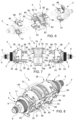
Figures 1, 2 and 3 are perspective views of the connection unit in different operating positions; -
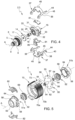
Figure 4 is an exploded perspective view of a female connector of the connection unit of the previous figures; -
Figure 5 is an exploded perspective view of a coupling element of the connection unit ofFigures 1-3 ; -
Figure 6 is a view corresponding to the views inFigure 1 , with parts shown in transparency for greater clarity; -
Figure 7 is a side view and partial section of the connection unit in a position corresponding to the view inFigure 1 , with parts removed for clarity's sake; -
Figure 8 is a view corresponding to the views inFigure 2 , with parts shown in transparency for greater clarity; -
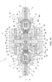
Figure 9 is an axial section of the connection unit in the operating position ofFigures 2 and8 ; -
Figure 10 is an axial section of the connection unit in the operating position ofFigure 3 ; and -
Figure 11 is a perspective view of the connection unit in the operating position ofFigures 3 and10 , with parts shown in transparency for greater clarity. - The present invention will now be described in detail with reference to the accompanying Figures to enable a skilled person to realize and use it. Various modifications to the embodiments presented shall be immediately clear to persons skilled in the art and the general principles disclosed herein could be applied to other embodiments and applications but without thereby departing from the scope of protection of the present invention as defined in the appended claims. Therefore, the present invention should not be considered limited to the embodiments described and shown but should be granted the widest protective scope in accordance with the features described and claimed.
- In order to facilitate understanding of the embodiments described herein, reference will be made to some specific embodiments and a specific language will be used to describe them. The terminology used herein is for the purpose of describing only particular embodiments, and is not intended to limit the scope of the present invention.
- With reference to
Figures 1 to 3, 1 denotes as a whole a connection unit for fluidic lines realized according to the invention. Theunit 1 is shown in a disconnection configuration (i.e. broken down into its elements) inFigure 1 , in a mechanical pre-connection configuration inFigure 2 and in a mechanical and fluidic connection position inFigure 3 . - The
unit 1, of axis A, essentially comprises afirst connector 2, asecond connector 3 and acoupling element 4 interposed between theconnectors - The
connectors connector 2, therefore also applies to theconnector 3. - The connector 2 (visible in greater detail in
Figures 4 and8 to 10 ) comprises anipple 5 provided with a cup-shaped body 6 defining within it a cylindrical cavity 7 delimited axially by a flat annularintermediate wall 8 and with a threadedtubular fitting 9 extending axially cantilevered from theintermediate wall 8 and defining aconduit 10 leading into the cavity 7. - The thread of the
fitting 9 is designed for fluidic connection of theconnector 2 to a respective branch of a fluidic circuit not shown. This branch may consist of an apparatus, for example a pump, a compressor or a utility of any nature, or a fluidic line, for example a pneumatic conduit or a pipeline for transporting a liquid, for example water, hydraulic oil, gas or in general fluids of any nature, including organic. - The cup-
shaped body 6 has anexternal thread 11 designed to allow the mechanical connection with a fixed bulkhead (not shown), through which theconnector 2 can be mounted passing through. The bulkhead may consist of a wall or a panel forming part of an apparatus. - The connector 2 (
Figures 4 ,9 and10 ) further includes adistributor 14 in the form of a cylindrical disc housed in the cavity 7 of thenipple 5 and abody 15 partially housed in the cavity 7, in axial contact with thedistributor 14. Thedistributor 14 and thebody 15 define a plurality ofchannellings 16 for the fluid of complex shape, in order to minimise pressure losses, and are conveniently obtained by means of an additive manufacturing technique (3D printing). Thesechannellings 16 are clearly visible inFigure 11 , where the parts of theconnection unit 1 are shown in transparency. - More specifically, the
distributor 14 has a firstflat face 17 placed in axial contact with theintermediate wall 8 and a secondflat face 18 placed in axial contact with the body 15 (Figures 9 and10 ). Thepart 16a of thechannellings 16 realized in thedistributor 14 comprises acentral chamber 19 directly facing theconduit 10 and a plurality ofconduits 20 extending radially in a radial pattern from thechamber 19 and lead axially on thesecond face 18. Thechamber 19 is closed towards the second face 18 (Figure 11 ). - The
body 15, substantially cylindrical in shape, has afirst base face 23 arranged in axial sealing abutment with thesecond face 18 of thedistributor 14 and a secondopposite base face 24. - The
part 16b of thechannellings 16 realized in thebody 15 comprises an axial throughconduit 25 and a plurality ofconduits 26 which lead axially on thefirst face 23 at theconduits 20 and extend radially in a radial pattern towards anend zone 27 of theconduit 25 opposite thefirst face 23, into which they open formingopenings 28. - Conveniently, at the exit holes of the
conduits respective faces distributor 14 and of thebody 15, respectiveannular grooves Figure 11 ) which fluidically connects theconduits - In the
conduit 25 there is sealingly housed apiston 30 axially slidable between an advanced position (Figure 9 ) in which it occupies theend zone 27 of theconduit 25 and therefore closes theexit openings 28 of theconduits 26, and a retracted position (Figure 10 ) adjacent to thedistributor 14. The advanced position of thepiston 30 is defined by the contact between the piston and an innerannular projection 31 at the end of theconduit 25, and is maintained by aspring 21 housed in theconduit 26 between thedistributor 20 and thepiston 30. - Finally, the
body 15 comprises a substantiallyquadrangular flange 32 extending radially from an outer surface of the body in proximity to thefirst face 23. Twocylindrical pins 33 coaxial to each other extend in a radial direction on opposite sides of theflange 32. - Finally, the
body 15 has anannular projection 34 extending axially from an outer edge of thesecond face 24 and delimiting acylindrical seat 35 for coupling with thecoupling element 4, as described below. - The
connector 2 is also provided with apre-coupling clamp 36 visible inFigures 4 and8 . - The
clamp 36 comprises twojaws 37 hinged around theirrespective pins 33. Each of thejaws 37 comprises a pair ofblades 38 extending axially on opposite sides of thebody 15 and having aproximal end 39 hinged to therespective pin 33 and adistal end 40. - The blades 38 (
Figure 8 ) comprise, on their longitudinal sides facing each other, respective lead-inchamfers 44 diverging towards the distal ends 40, and respective axially elongatedintermediate recesses 45 facing each other. - The
jaws 37 further compriserespective connection plates 46 which integrally connect respective outer intermediate zones of theblades 38 of each jaw to each other and are arched so as to extend around thebody 15. - The
jaws 37 are loaded by springs 47 (Figure 8 ) wound around therespective pins 33 and tending to keep them in a closed position. - With reference to
Figures 5 and8-10 , thecoupling element 4 comprises a double-male connector 50 separable from thefemale connectors body 51 enclosing theconnector 50, and a pair ofpistons 52 sliding within thebody 51. - More particularly, the
connector 50 comprises an axialtubular element 62, of elongated cylindrical shape, defining in its inside a centralaxial conduit 53 closed at the ends. In proximity to its opposite axial ends, thetubular element 62 has a plurality ofradial openings 54 extending in a radial pattern from and communicating with the conduit 53 (fig. 5 ). Theopenings 54 correspond in number and spatial arrangement to theexit openings 28 of theconduits 26 in thecentral conduit 25 of thebody 15, as will be further explained below. - The
connector 50 further comprises anintermediate plate 55, extending radially and integrally from thetubular element 62 in a plane orthogonal to the axis A and having a substantially quadrangular shape (Figure 5 ) with twoflat sides 56 and twosides 57 that are curved two by two and opposite. Theplate 55 divides thetubular element 62 into twocylindrical shanks 68, each of which functions as a male connection element designed to couple with a respectivefemale connector - The
plate 55 is provided with a plurality of blindradial chambers 59 fluidically connected to thecentral conduit 53 byradial passages 60. - The
body 51 is divided into two substantiallycylindrical parts outer flange 64 and an inner annular projection 65 (fig. 10 ). Theflanges 64 rest on respective opposite faces of theplate 55 and are fixed to each other by means of a plurality ofscrews 66 passing through the plate 55 (Figures 9 ,10 ), thus forming thebody 51. Thebody 51 defines with the tubular element 62 a pair ofannular chambers 67, arranged on axially opposite sides of theplate 55. Thepistons 52 are housed sealingly and slidably in therespective chambers 67 and have, on one end opposite theplate 55, anannular end projection 69 designed to cooperate with therespective body 15 by being sealingly housed in the correspondingcylindrical seat 35 of the body. Thepistons 52 are normally kept in contact with the innerannular projections 65 of thebody 51 byrespective springs 63 housed in theannular chambers 67. - From the
flange 64 of each half 51a, 51b of thebody 51, two radially opposedrungs 58 extend radially outwards, the function of which will be clarified below. - All sliding seals are realized by means of sealing rings, and are preferably redundant, i.e. they include two sealing rings in series along each path of possible leakage. A detailed description of the sealing rings and of their position is considered superfluous, as it is within the reach of a person skilled in the art.
- Finally, the
coupling element 4 comprises an externalannular ring 70 coaxial to thebody 50 and formed by twoparts plate 55, which is rotatably housed within an internal groove 71 formed by the twoparts Figure 7 ). Thering 70 has two diametricallyopposite projections 72, each of which extends axially on both sides and forms on its own outer surface a substantially elongatedrectangular area 73 on which identification marks may be printed or affixed in any way, as will be further described below. - The
ring nut 70, as can be seen in particular fromFigure 5 andFigure 7 (in which all parts of thecoupling element 4 are omitted for clarity's sake), has within it ramp-like grooves 74 designed to cooperate withrespective rungs 75 carried by thejaws 37 of theclamps 36 to form respective bayonet couplings between thecoupling element 4 and each of theconnectors - More particularly, the
rungs 75 radially extend in positions that are diametrically opposite between them from therespective jaws 37 of theclamp 36 of eachconnector clamp 36 is in the closed position, as will be better described below. - The
grooves 74 inside the ring nut 70 (only two of which are visible inFigure 7 ) extend circumferentially for 90° and have acircumferential entry opening 76, arranged at a side of a respective projection 71 and in proximity to afront face 77 of the ring nut, a ramp-like portion 78 extending towards the centre of thering nut 50 and a substantially circumferentialblind end portion 79 with anend 79a defining a slight recess turned axially towards therespective connector 5. - Finally, the
connection unit 1 includes akey system 80 designed to prevent the wrong coupling between connectors belonging to different fluidic lines. Thekey system 80, visible in detail inFigures 4 to 6 , consist of a pair ofkeys 81 carried by eachfemale connector keys 82 carried by thecoupling element 4 and designed to couple axially with therespective keys 81 at the time of coupling between theconnectors coupling element 4. - The
keys keys - More specifically, with reference to
Figure 6 , thekeys 81 may be shaped plates mounted interlockingly within theconnection plates 46 of thejaws 37, while thekeys 82 may comprise a base 83 designed to be fixed frontally on therespective flange 64 of thebody 51 of thecoupling element 4 and a plurality ofaxial projections 84 extending cantilevered from thebase 83. Theprojections 84 and thekeys 81 have complementary shapes to allow a sliding axial coupling. - Conveniently, at least one of the
keys 81 of eachconnector radial projection 85 terminating in an axially foldedappendage 86, the function of which will be clarified below. - The operation of the
connection unit 1 is as follows. - In
Figures 1 ,6 and 7 the unit is shown in the disconnection position, where bothconnectors coupling element 4. - In this condition, the
connectors springs 21 keep thepistons 30 in the end-of-stroke position shown inFigure 9 in which they occupy theend zone 27 of therespective conduits 25 and close theexit openings 28 of theconduits 26. - By bringing the
connectors coupling element 4, which are suitably aligned with each other axially and circumferentially, thekeys keys jaws 37 around thepins 33 in the direction of the opening of the jaws, so that any further axial approach between theconnectors coupling element 4 is prevented and the connection is impossible. - If the connection is correct, i.e. the
keys keys jaws 37 of theclamps 36 of theconnectors respective rungs 58 of thecoupling element 4. The latter are wedged between thechamfers 44 of theblades 38 causing them to open against the action of thesprings 47. When therungs 58 engage therecesses 45, thejaws 37 snap close under the thrust of thesprings 47, resulting in a mechanical pre-coupling condition between theconnectors Figures 2 ,8 and9 ). - Note that the
recesses 45 are axially elongated, so as to allow a further axial approach between theconnectors coupling element 4 from the pre-coupling condition. - It should also be noted that this condition results in a mechanical but not fluidic connection. In fact, with specific reference to
Figure 9 , in this mechanical pre-coupling condition, thebodies 15 of theconnectors pistons 52 of thecoupling element 4, whoseprojections 34 engage therespective seats 35, but thepistons 52 remain in the end-of-stroke position in contact with theprojections 65 and therefore keep theopenings 54 closed. Furthermore, thepistons 30 of theconnectors tubular element 62 but remain in theend zone 27 of theconduits 29, thus keeping theopenings 28 closed. - In order to realize a fluidic seal, the
ring nut 70 must be turned by 90° bringing it from the position shown inFigure 2 to the one inFigure 3 . - As can be noted from
Figure 2 , in the pre-coupling positions, therungs 75 of thejaws 37 of theconnectors entry openings 76 of the ramp-like grooves 74 of thecoupling element 4. By turning thering nut 70, therungs 75 enter therespective grooves 74 and run through them until they reach theends 79a, where they are blocked. Due to the ramp shape of thegrooves 74, this results in an axial displacement of theconnectors coupling element 4. - In particular, with reference to
Figure 10 , the ends of thetubular element 62 axially penetrate inside thecentral conduits 25 of thebodies 15 of theconnectors pistons 30 against the action of thesprings 21. Thepistons 28 therefore uncover theopenings 28. - At the same time, the
pistons 52 of thecoupling element 4, due to the axial contact with thebodies 15 of theconnectors plate 55 in therespective chambers 67, against the action of thesprings 53. In this way, thepistons 52 uncover theopenings 54, which are located at theopenings 28. A connection is therefore established between theconduits 26 of theconnectors central conduit 53 of thetubular element 52, as can be clearly seen inFigure 11 where these conduits are highlighted. - Once the unit is connected, the projections 71 of the
ring nut 70 are aligned with theappendages 86 of thekeys 81, visually confirming the completion of the connection. Where an automatic handling of the unit is envisaged, a code, for example a bar code, may be affixed partly to the projections 71 and partly to the associatedones 86. In this way, the code is completed and can only be read after successful connection. - In the above description, the unit has been shown for clarity's sake as formed by three elements (the
connectors coupling element 4 is conveniently pre-mounted on one of the twofemale connectors unit 1 will therefore involve the connection of two sub-units, one constituted by the set of a first connector (e.g. The connector 2) and of thecoupling element 4 and the other one by thesecond connector 3. This connection will therefore involve an initial pre-coupling phase of theconnector 3, and a fluidic connection phase by rotation of thering nut 70. - From an examination of the characteristics of the
connection unit 1 realized according to the present invention, the advantages that it allows to obtain are evident. - Firstly, the use of two
female connectors - Another advantage of the unit is the simplicity of the movements required for connection, which include a rotation of a fraction of a revolution, in the example shown 90°. As a result, the connection of the unit can be easily realized by using automatic manipulators.
- A further advantage is the inhibition of the connection if the keys of the connectors and the coupling element do not match.
- Further assurance of the reliability of the connection is provided by the display of the alignment between one of the projections 71 of the
ring nut 70 with theappendages 86 of thekeys 81, and by the possibility of using this alignment to form a machine-readable code. - Finally, the presence of a compensation volume (constituted in the example shown by the
chambers 59 in the plate 55) connected in derivation to the fluid path in the unit allows the absorption, at least in part, of possible pressure waves (water hammer) due to the sudden connection of branches of the circuit placed at different pressures. - Finally, it is clear that changes and variations can be made to the
unit 1 described that do not go beyond the scope of protection defined by the claims. - In particular, the bayonet coupling between the
coupling element 4 and theconnectors - The
ring nut 70 can therefore be replaced by a control element of different type, e.g. a lever. - The specific realization of the sealing elements within the
connectors coupling element 4 may be different. - The
chambers 59 can be replaced or integrated by compensation volumes arranged in other parts of the connection unit, e.g. in theconnectors
Claims (13)
- Connection unit including a first and a second connector (2, 3) configured to be connected to respective circuit branches of a fluidic line and a coupling element (4) for coupling said connectors (2, 3) together and establish a fluidic connection between said circuit branches, said connectors (2, 3) being provided with first, normally closed sealing elements (30) to define a sealing termination of said circuit branches when the connectors (2, 3) are disconnected from each other,characterized in that both said connectors are female connectors (2, 3);and in that the coupling element (4) includes a double-male connector (50) separable from the female connectors (2, 3) and provided with a pair of shanks (68) that can be coupled to the respective female connectors (2, 3) and a control element (70) movable between a first position where the coupling element (4) can be coupled to the connectors (2, 3) in a mechanical pre-coupling condition without fluidic connection between the female connectors (2, 3) and a second position where the shanks (68) of the double-male connector (50) engage the respective female connectors (2, 3) and establish a fluidic connection therebetween.
- Connection unit as claimed in claim 1, including a mechanism configured to axially move the connectors (2, 3) closer to the coupling element (4) in response to the movement of the control element (70) between the first and second position.
- Connection unit as claimed in claim 1 or 2, wherein the motion of the control element (70) from the first to the second position is a rotation of amplitude equal to a fraction of a revolution.
- Connection unit as claimed in claim 2 or 3, wherein said control element is a ring nut (70) and said mechanism is a bayonet coupling (74; 75).
- Connection unit as claimed in any of the preceding claims, wherein the connectors include a nipple for connection to the respective circuit branch and defining a first conduit (10) communicating fluidly, in use, with the respective circuit branch, and a second conduit (25) that can be engaged by a respective shank (68) of the double-male connector (50), said first and second conduit (20; 25) being connected by at least one channel (20, 26) leading into the second conduit (25) through at least one radial opening (28), said first sealing elements of the female connectors (2, 3) including a piston (30) housed slidably in the second conduit and movable under the thrust of the respective shank (68) to uncover said at least one opening (28).
- Connection unit as claimed in claim 5, wherein the shanks (68) of the double-male connector (50) are closed at their ends and have at least one radial opening (54) designed to match the at least one opening of the respective connector (2, 3).
- Connection unit as claimed in claim 6, wherein the coupling element (4) includes second sealing elements (52) slidable on the respective shanks (68) and selectively cooperating sealingly with said at least one radial opening (54), said second sealing elements (52) being movable upon contact with the respective female connectors (2, 3) to uncover said at least one radial opening (54) when the shanks (68) engage the respective second conduits (25).
- Connection units as claimed in one of the above claims, wherein the connectors and the coupling element include respective keys (81, 82) corresponding to a given fluidic line, said keys (81, 82) being configured to prevent coupling between the connectors (2, 3) and the coupling element (4) in case of attempted connection of circuit branches belonging to different fluidic lines.
- Connection unit as claimed in any of the above claims, wherein the mechanical pre-coupling position is defined by the elastic coupling between a clamp (36) carried by one of the connectors (2, 3) and at least one rung carried by the coupling element (4), or vice versa.
- Connection unit as claimed in claim 9, wherein the keys (81, 82) are configured to prevent the clamp (36) from closing in case of incorrect connection.
- Connection unit as claimed in any of the above claims, wherein at least one of the connectors (2, 3) and the coupling element (4) includes at least one compensation volume (59).
- Connection unit as claimed in one of the claims 4 to 11, wherein the connectors (2,3) and the ring nut (70) have respective visual indicia (86, 71) aligned with each other in the second position of the ring nut (70).
- Connection unit Unit as claimed in claim 12, wherein the visual indicia (86, 71) define together an automatically readable code.
Applications Claiming Priority (3)
| Application Number | Priority Date | Filing Date | Title |
|---|---|---|---|
| EP20184051 | 2020-07-03 | ||
| IT202000022447 | 2020-09-23 | ||
| PCT/IB2021/055970 WO2022003648A1 (en) | 2020-07-03 | 2021-07-02 | Connection units for quick connection/disconnection fluidic lines |
Publications (2)
| Publication Number | Publication Date |
|---|---|
| EP4176193A1 EP4176193A1 (en) | 2023-05-10 |
| EP4176193B1 true EP4176193B1 (en) | 2023-11-15 |
Family
ID=77180298
Family Applications (1)
| Application Number | Title | Priority Date | Filing Date |
|---|---|---|---|
| EP21749697.5A Active EP4176193B1 (en) | 2020-07-03 | 2021-07-02 | Connection units for quick connection/disconnection fluidic lines |
Country Status (4)
| Country | Link |
|---|---|
| US (1) | US12188598B2 (en) |
| EP (1) | EP4176193B1 (en) |
| JP (1) | JP7753265B2 (en) |
| WO (1) | WO2022003648A1 (en) |
Families Citing this family (3)
| Publication number | Priority date | Publication date | Assignee | Title |
|---|---|---|---|---|
| IT201900019322A1 (en) * | 2019-10-18 | 2021-04-18 | Thales Alenia Space Italia Spa Con Unico Socio | END-TO-END ASSISTANCE IN ORBIT |
| IT202400002449A1 (en) * | 2024-02-06 | 2025-08-06 | Thales Alenia Space Italia Spa Con Unico Socio | QUICK CONNECT/DISCONNECT FLUID LINE CONNECTION UNIT |
| IT202400002446A1 (en) | 2024-02-06 | 2025-08-06 | Thales Alenia Space Italia Spa Con Unico Socio | QUICK CONNECT/DISCONNECT FLUID LINE CONNECTION UNIT WITH DUST BARRIER |
Family Cites Families (40)
| Publication number | Priority date | Publication date | Assignee | Title |
|---|---|---|---|---|
| US2393489A (en) * | 1944-08-26 | 1946-01-22 | Bendix Aviat Corp | Fluid coupling |
| US2457251A (en) * | 1945-03-28 | 1948-12-28 | Aeroquip Corp | Quick connect self-sealing coupling |
| GB607340A (en) * | 1946-01-30 | 1948-08-30 | Tecalemit Ltd | Improvements relating to couplings for use in fluid supply systems |
| US2509444A (en) * | 1947-06-17 | 1950-05-30 | M B G Corp | Fluid coupling |
| US2625410A (en) * | 1949-05-07 | 1953-01-13 | North American Aviation Inc | Coupling |
| US2687314A (en) * | 1950-06-26 | 1954-08-24 | Aeroquip Corp | Self-sealing coupling |
| US2934359A (en) * | 1957-01-31 | 1960-04-26 | Aeroquip Corp | Locking structure for self-sealing coupling |
| US3120968A (en) * | 1960-04-21 | 1964-02-11 | John H Calvin | Quick disconnect coupling with ring detent |
| US3167092A (en) | 1960-10-20 | 1965-01-26 | Tech Quip | Quick disconnect coupling |
| US3217746A (en) * | 1962-10-30 | 1965-11-16 | Brock Ind Inc | Fluid valve coupling with interlocking lugs |
| US3474827A (en) * | 1966-02-09 | 1969-10-28 | Emco Wheaton | Coupler and adapter and seal structure therefor |
| US3664634A (en) * | 1968-09-19 | 1972-05-23 | Robert W Guertin | Valve seal for coupling device |
| US4280723A (en) * | 1978-07-26 | 1981-07-28 | Moldestad Jon P | Safety device for hose connections |
| US4211439A (en) * | 1978-07-26 | 1980-07-08 | Moldestad Jon P | Safety device for hose connections |
| US4271865A (en) * | 1979-05-14 | 1981-06-09 | Galloway Robert L | Dry break coupling valve |
| US4327770A (en) * | 1979-11-23 | 1982-05-04 | Outboard Marine Corporation | Quick disconnect fluid line coupling |
| DE3041909C2 (en) * | 1980-11-06 | 1983-12-01 | Argus Verwaltungsgesellschaft Mbh, 7505 Ettlingen | Quick release coupling for fluid lines |
| US4986304A (en) * | 1990-01-16 | 1991-01-22 | Ingersoll-Rand Company | Quick and dry coupling |
| US5009252A (en) * | 1990-05-03 | 1991-04-23 | The United States Of America As Represented By The Secretary Of The Army | Air distribution connector valve |
| US5211197A (en) * | 1992-01-03 | 1993-05-18 | Aeroquip Corporation | Quick disconnect liquid line coupling with volumertric expansion couping element |
| US5320326A (en) * | 1993-06-11 | 1994-06-14 | Ted Ju | Improved structure of a quick-connect pipe fitting |
| JPH09144970A (en) * | 1995-11-17 | 1997-06-03 | Nichirin:Kk | One-touch type self-sealing fitting |
| US6161578A (en) * | 1996-10-09 | 2000-12-19 | Colder Products Company | Low spill high flow quick coupling valve assembly |
| US5884648A (en) * | 1997-08-27 | 1999-03-23 | Scholle Corporation | Coupling valve apparatus and method |
| JP3299495B2 (en) * | 1997-12-29 | 2002-07-08 | サーパス工業株式会社 | Misconnection prevention connector |
| US7762278B2 (en) * | 2003-07-29 | 2010-07-27 | Societe Bic | Valves for fuel cartridges |
| GB0415637D0 (en) * | 2004-07-13 | 2004-08-18 | Self Energising Coupling Compa | Coupling assembly |
| DE102010019094A1 (en) * | 2010-04-30 | 2011-11-03 | Rheinisch-Westfälische Technische Hochschule Aachen | Hydraulic coupling sleeve |
| WO2012024624A1 (en) * | 2010-08-20 | 2012-02-23 | Py Daniel C | Connector and related method |
| FR3017689B1 (en) * | 2014-02-17 | 2016-03-11 | Staubli Sa Ets | BAIONNETTE CONNECTOR SUITABLE FOR REMOVABLE JUNCTION OF PIPELINES |
| WO2016025877A2 (en) * | 2014-08-14 | 2016-02-18 | Flomax International, Inc. | Nozzle and keyed flush face receiver |
| CN110608330B (en) | 2015-04-20 | 2021-05-07 | 考尔得产品公司 | Single-use sterile fluid coupling |
| WO2017057720A1 (en) * | 2015-10-02 | 2017-04-06 | 日東工器株式会社 | Pipe joint |
| US9909703B2 (en) | 2015-12-31 | 2018-03-06 | Dixon Quick Coupling | Fluid coupling and method |
| GB2549287B (en) * | 2016-04-11 | 2019-07-24 | Self Energising Coupling Co Ltd | Fluid coupling with cam and follower controlled securing means |
| JP6901873B2 (en) * | 2017-03-03 | 2021-07-14 | サーパス工業株式会社 | Fluid equipment |
| DE102017005588A1 (en) | 2017-06-13 | 2018-12-13 | Messer France S.A.S. | Clutch for cryogenic liquefied media |
| US10253911B1 (en) * | 2017-09-29 | 2019-04-09 | AdelWiggins Group, a Division of Transdigm Inc. | Quick disconnect coupling with selective mating capability |
| KR20200019347A (en) * | 2018-08-14 | 2020-02-24 | 하금선 | Connecting structure for water intake of mobile water supplier |
| CN111810745A (en) | 2020-07-08 | 2020-10-23 | 嘉兴市盛央电气有限公司 | Ball Lock Push-In Fluid Connectors |
-
2021
- 2021-07-02 US US18/013,845 patent/US12188598B2/en active Active
- 2021-07-02 JP JP2022580984A patent/JP7753265B2/en active Active
- 2021-07-02 EP EP21749697.5A patent/EP4176193B1/en active Active
- 2021-07-02 WO PCT/IB2021/055970 patent/WO2022003648A1/en not_active Ceased
Also Published As
| Publication number | Publication date |
|---|---|
| EP4176193A1 (en) | 2023-05-10 |
| US12188598B2 (en) | 2025-01-07 |
| WO2022003648A1 (en) | 2022-01-06 |
| US20230288003A1 (en) | 2023-09-14 |
| JP2023532706A (en) | 2023-07-31 |
| JP7753265B2 (en) | 2025-10-14 |
Similar Documents
| Publication | Publication Date | Title |
|---|---|---|
| US12188598B2 (en) | Connection units for quick connection/disconnection fluidic lines | |
| US20230094260A1 (en) | Connection assembly and thermoregulation assembly | |
| KR930004155Y1 (en) | Double pipe joint | |
| US3731705A (en) | Fluid coupling | |
| US3545490A (en) | Fluid conduit coupling | |
| CN106907542B (en) | Male or female quick coupling element and quick coupling comprising such an element | |
| EP2431646B1 (en) | Coaxial quick coupling | |
| US20060130910A1 (en) | Quick coupling | |
| US4776614A (en) | Coupling with lock indicator | |
| US10851929B2 (en) | Fluid coupling | |
| EP2831483B1 (en) | Sealed coupling device | |
| WO1988008499A1 (en) | Straight connecting hydraulic quick coupler | |
| US5129417A (en) | Valve including a closing device and sealed connectors | |
| US7044155B2 (en) | Joint-type coaxial connection | |
| US4799512A (en) | Coupling assembly | |
| US3254673A (en) | Quick disconnect coupling with valve | |
| US11435018B2 (en) | Hydraulic multi-coupling with independent single handle rotational disconnect | |
| EP0122987B1 (en) | Ball valve coupling | |
| EP3662189B1 (en) | Hydraulic and/or pneumatic connector assembly | |
| EP3332163B1 (en) | Quick coupling | |
| US4637294A (en) | Device for controlling the supply of fluid under pressure to a hydrauic circuit as a function of the state of locking of unlocking of two mechanical members | |
| JPH026397B2 (en) | ||
| US20250198553A1 (en) | Poppet coupling | |
| US4997160A (en) | Ball lock control valve actuation plunger - hydraulic type | |
| WO2025169003A1 (en) | Quick connect/disconnect connection unit for fluidic lines |
Legal Events
| Date | Code | Title | Description |
|---|---|---|---|
| STAA | Information on the status of an ep patent application or granted ep patent |
Free format text: STATUS: UNKNOWN |
|
| STAA | Information on the status of an ep patent application or granted ep patent |
Free format text: STATUS: THE INTERNATIONAL PUBLICATION HAS BEEN MADE |
|
| PUAI | Public reference made under article 153(3) epc to a published international application that has entered the european phase |
Free format text: ORIGINAL CODE: 0009012 |
|
| STAA | Information on the status of an ep patent application or granted ep patent |
Free format text: STATUS: REQUEST FOR EXAMINATION WAS MADE |
|
| 17P | Request for examination filed |
Effective date: 20221228 |
|
| AK | Designated contracting states |
Kind code of ref document: A1 Designated state(s): AL AT BE BG CH CY CZ DE DK EE ES FI FR GB GR HR HU IE IS IT LI LT LU LV MC MK MT NL NO PL PT RO RS SE SI SK SM TR |
|
| GRAP | Despatch of communication of intention to grant a patent |
Free format text: ORIGINAL CODE: EPIDOSNIGR1 |
|
| STAA | Information on the status of an ep patent application or granted ep patent |
Free format text: STATUS: GRANT OF PATENT IS INTENDED |
|
| P01 | Opt-out of the competence of the unified patent court (upc) registered |
Effective date: 20230518 |
|
| DAV | Request for validation of the european patent (deleted) | ||
| DAX | Request for extension of the european patent (deleted) | ||
| INTG | Intention to grant announced |
Effective date: 20230607 |
|
| GRAS | Grant fee paid |
Free format text: ORIGINAL CODE: EPIDOSNIGR3 |
|
| GRAA | (expected) grant |
Free format text: ORIGINAL CODE: 0009210 |
|
| STAA | Information on the status of an ep patent application or granted ep patent |
Free format text: STATUS: THE PATENT HAS BEEN GRANTED |
|
| AK | Designated contracting states |
Kind code of ref document: B1 Designated state(s): AL AT BE BG CH CY CZ DE DK EE ES FI FR GB GR HR HU IE IS IT LI LT LU LV MC MK MT NL NO PL PT RO RS SE SI SK SM TR |
|
| REG | Reference to a national code |
Ref country code: CH Ref legal event code: EP Ref country code: GB Ref legal event code: FG4D |
|
| REG | Reference to a national code |
Ref country code: DE Ref legal event code: R096 Ref document number: 602021006896 Country of ref document: DE |
|
| REG | Reference to a national code |
Ref country code: IE Ref legal event code: FG4D |
|
| REG | Reference to a national code |
Ref country code: NL Ref legal event code: FP |
|
| REG | Reference to a national code |
Ref country code: LT Ref legal event code: MG9D |
|
| PG25 | Lapsed in a contracting state [announced via postgrant information from national office to epo] |
Ref country code: GR Free format text: LAPSE BECAUSE OF FAILURE TO SUBMIT A TRANSLATION OF THE DESCRIPTION OR TO PAY THE FEE WITHIN THE PRESCRIBED TIME-LIMIT Effective date: 20240216 |
|
| PG25 | Lapsed in a contracting state [announced via postgrant information from national office to epo] |
Ref country code: IS Free format text: LAPSE BECAUSE OF FAILURE TO SUBMIT A TRANSLATION OF THE DESCRIPTION OR TO PAY THE FEE WITHIN THE PRESCRIBED TIME-LIMIT Effective date: 20240315 |
|
| PG25 | Lapsed in a contracting state [announced via postgrant information from national office to epo] |
Ref country code: LT Free format text: LAPSE BECAUSE OF FAILURE TO SUBMIT A TRANSLATION OF THE DESCRIPTION OR TO PAY THE FEE WITHIN THE PRESCRIBED TIME-LIMIT Effective date: 20231115 |
|
| REG | Reference to a national code |
Ref country code: AT Ref legal event code: MK05 Ref document number: 1632072 Country of ref document: AT Kind code of ref document: T Effective date: 20231115 |
|
| PG25 | Lapsed in a contracting state [announced via postgrant information from national office to epo] |
Ref country code: AT Free format text: LAPSE BECAUSE OF FAILURE TO SUBMIT A TRANSLATION OF THE DESCRIPTION OR TO PAY THE FEE WITHIN THE PRESCRIBED TIME-LIMIT Effective date: 20231115 |
|
| PG25 | Lapsed in a contracting state [announced via postgrant information from national office to epo] |
Ref country code: ES Free format text: LAPSE BECAUSE OF FAILURE TO SUBMIT A TRANSLATION OF THE DESCRIPTION OR TO PAY THE FEE WITHIN THE PRESCRIBED TIME-LIMIT Effective date: 20231115 |
|
| PG25 | Lapsed in a contracting state [announced via postgrant information from national office to epo] |
Ref country code: LT Free format text: LAPSE BECAUSE OF FAILURE TO SUBMIT A TRANSLATION OF THE DESCRIPTION OR TO PAY THE FEE WITHIN THE PRESCRIBED TIME-LIMIT Effective date: 20231115 Ref country code: IS Free format text: LAPSE BECAUSE OF FAILURE TO SUBMIT A TRANSLATION OF THE DESCRIPTION OR TO PAY THE FEE WITHIN THE PRESCRIBED TIME-LIMIT Effective date: 20240315 Ref country code: GR Free format text: LAPSE BECAUSE OF FAILURE TO SUBMIT A TRANSLATION OF THE DESCRIPTION OR TO PAY THE FEE WITHIN THE PRESCRIBED TIME-LIMIT Effective date: 20240216 Ref country code: ES Free format text: LAPSE BECAUSE OF FAILURE TO SUBMIT A TRANSLATION OF THE DESCRIPTION OR TO PAY THE FEE WITHIN THE PRESCRIBED TIME-LIMIT Effective date: 20231115 Ref country code: BG Free format text: LAPSE BECAUSE OF FAILURE TO SUBMIT A TRANSLATION OF THE DESCRIPTION OR TO PAY THE FEE WITHIN THE PRESCRIBED TIME-LIMIT Effective date: 20240215 Ref country code: AT Free format text: LAPSE BECAUSE OF FAILURE TO SUBMIT A TRANSLATION OF THE DESCRIPTION OR TO PAY THE FEE WITHIN THE PRESCRIBED TIME-LIMIT Effective date: 20231115 Ref country code: PT Free format text: LAPSE BECAUSE OF FAILURE TO SUBMIT A TRANSLATION OF THE DESCRIPTION OR TO PAY THE FEE WITHIN THE PRESCRIBED TIME-LIMIT Effective date: 20240315 |
|
| PG25 | Lapsed in a contracting state [announced via postgrant information from national office to epo] |
Ref country code: SE Free format text: LAPSE BECAUSE OF FAILURE TO SUBMIT A TRANSLATION OF THE DESCRIPTION OR TO PAY THE FEE WITHIN THE PRESCRIBED TIME-LIMIT Effective date: 20231115 Ref country code: RS Free format text: LAPSE BECAUSE OF FAILURE TO SUBMIT A TRANSLATION OF THE DESCRIPTION OR TO PAY THE FEE WITHIN THE PRESCRIBED TIME-LIMIT Effective date: 20231115 Ref country code: PL Free format text: LAPSE BECAUSE OF FAILURE TO SUBMIT A TRANSLATION OF THE DESCRIPTION OR TO PAY THE FEE WITHIN THE PRESCRIBED TIME-LIMIT Effective date: 20231115 Ref country code: NO Free format text: LAPSE BECAUSE OF FAILURE TO SUBMIT A TRANSLATION OF THE DESCRIPTION OR TO PAY THE FEE WITHIN THE PRESCRIBED TIME-LIMIT Effective date: 20240215 Ref country code: LV Free format text: LAPSE BECAUSE OF FAILURE TO SUBMIT A TRANSLATION OF THE DESCRIPTION OR TO PAY THE FEE WITHIN THE PRESCRIBED TIME-LIMIT Effective date: 20231115 Ref country code: HR Free format text: LAPSE BECAUSE OF FAILURE TO SUBMIT A TRANSLATION OF THE DESCRIPTION OR TO PAY THE FEE WITHIN THE PRESCRIBED TIME-LIMIT Effective date: 20231115 |
|
| PG25 | Lapsed in a contracting state [announced via postgrant information from national office to epo] |
Ref country code: DK Free format text: LAPSE BECAUSE OF FAILURE TO SUBMIT A TRANSLATION OF THE DESCRIPTION OR TO PAY THE FEE WITHIN THE PRESCRIBED TIME-LIMIT Effective date: 20231115 |
|
| PG25 | Lapsed in a contracting state [announced via postgrant information from national office to epo] |
Ref country code: CZ Free format text: LAPSE BECAUSE OF FAILURE TO SUBMIT A TRANSLATION OF THE DESCRIPTION OR TO PAY THE FEE WITHIN THE PRESCRIBED TIME-LIMIT Effective date: 20231115 |
|
| PG25 | Lapsed in a contracting state [announced via postgrant information from national office to epo] |
Ref country code: SK Free format text: LAPSE BECAUSE OF FAILURE TO SUBMIT A TRANSLATION OF THE DESCRIPTION OR TO PAY THE FEE WITHIN THE PRESCRIBED TIME-LIMIT Effective date: 20231115 |
|
| PG25 | Lapsed in a contracting state [announced via postgrant information from national office to epo] |
Ref country code: SM Free format text: LAPSE BECAUSE OF FAILURE TO SUBMIT A TRANSLATION OF THE DESCRIPTION OR TO PAY THE FEE WITHIN THE PRESCRIBED TIME-LIMIT Effective date: 20231115 Ref country code: SK Free format text: LAPSE BECAUSE OF FAILURE TO SUBMIT A TRANSLATION OF THE DESCRIPTION OR TO PAY THE FEE WITHIN THE PRESCRIBED TIME-LIMIT Effective date: 20231115 Ref country code: RO Free format text: LAPSE BECAUSE OF FAILURE TO SUBMIT A TRANSLATION OF THE DESCRIPTION OR TO PAY THE FEE WITHIN THE PRESCRIBED TIME-LIMIT Effective date: 20231115 Ref country code: EE Free format text: LAPSE BECAUSE OF FAILURE TO SUBMIT A TRANSLATION OF THE DESCRIPTION OR TO PAY THE FEE WITHIN THE PRESCRIBED TIME-LIMIT Effective date: 20231115 Ref country code: DK Free format text: LAPSE BECAUSE OF FAILURE TO SUBMIT A TRANSLATION OF THE DESCRIPTION OR TO PAY THE FEE WITHIN THE PRESCRIBED TIME-LIMIT Effective date: 20231115 Ref country code: CZ Free format text: LAPSE BECAUSE OF FAILURE TO SUBMIT A TRANSLATION OF THE DESCRIPTION OR TO PAY THE FEE WITHIN THE PRESCRIBED TIME-LIMIT Effective date: 20231115 |
|
| REG | Reference to a national code |
Ref country code: DE Ref legal event code: R097 Ref document number: 602021006896 Country of ref document: DE |
|
| PLBE | No opposition filed within time limit |
Free format text: ORIGINAL CODE: 0009261 |
|
| STAA | Information on the status of an ep patent application or granted ep patent |
Free format text: STATUS: NO OPPOSITION FILED WITHIN TIME LIMIT |
|
| 26N | No opposition filed |
Effective date: 20240819 |
|
| PG25 | Lapsed in a contracting state [announced via postgrant information from national office to epo] |
Ref country code: SI Free format text: LAPSE BECAUSE OF FAILURE TO SUBMIT A TRANSLATION OF THE DESCRIPTION OR TO PAY THE FEE WITHIN THE PRESCRIBED TIME-LIMIT Effective date: 20231115 |
|
| PG25 | Lapsed in a contracting state [announced via postgrant information from national office to epo] |
Ref country code: SI Free format text: LAPSE BECAUSE OF FAILURE TO SUBMIT A TRANSLATION OF THE DESCRIPTION OR TO PAY THE FEE WITHIN THE PRESCRIBED TIME-LIMIT Effective date: 20231115 |
|
| PG25 | Lapsed in a contracting state [announced via postgrant information from national office to epo] |
Ref country code: MC Free format text: LAPSE BECAUSE OF FAILURE TO SUBMIT A TRANSLATION OF THE DESCRIPTION OR TO PAY THE FEE WITHIN THE PRESCRIBED TIME-LIMIT Effective date: 20231115 |
|
| REG | Reference to a national code |
Ref country code: CH Ref legal event code: PL |
|
| PG25 | Lapsed in a contracting state [announced via postgrant information from national office to epo] |
Ref country code: LU Free format text: LAPSE BECAUSE OF NON-PAYMENT OF DUE FEES Effective date: 20240702 |
|
| PG25 | Lapsed in a contracting state [announced via postgrant information from national office to epo] |
Ref country code: LU Free format text: LAPSE BECAUSE OF NON-PAYMENT OF DUE FEES Effective date: 20240702 |
|
| PG25 | Lapsed in a contracting state [announced via postgrant information from national office to epo] |
Ref country code: BE Free format text: LAPSE BECAUSE OF NON-PAYMENT OF DUE FEES Effective date: 20240731 Ref country code: CH Free format text: LAPSE BECAUSE OF NON-PAYMENT OF DUE FEES Effective date: 20240731 |
|
| REG | Reference to a national code |
Ref country code: BE Ref legal event code: MM Effective date: 20240731 |
|
| PG25 | Lapsed in a contracting state [announced via postgrant information from national office to epo] |
Ref country code: IE Free format text: LAPSE BECAUSE OF NON-PAYMENT OF DUE FEES Effective date: 20240702 |
|
| PGFP | Annual fee paid to national office [announced via postgrant information from national office to epo] |
Ref country code: NL Payment date: 20250724 Year of fee payment: 5 |
|
| PG25 | Lapsed in a contracting state [announced via postgrant information from national office to epo] |
Ref country code: FI Free format text: LAPSE BECAUSE OF FAILURE TO SUBMIT A TRANSLATION OF THE DESCRIPTION OR TO PAY THE FEE WITHIN THE PRESCRIBED TIME-LIMIT Effective date: 20231115 |
|
| PGFP | Annual fee paid to national office [announced via postgrant information from national office to epo] |
Ref country code: DE Payment date: 20250728 Year of fee payment: 5 |
|
| PGFP | Annual fee paid to national office [announced via postgrant information from national office to epo] |
Ref country code: IT Payment date: 20250627 Year of fee payment: 5 |
|
| PGFP | Annual fee paid to national office [announced via postgrant information from national office to epo] |
Ref country code: GB Payment date: 20250722 Year of fee payment: 5 |
|
| PGFP | Annual fee paid to national office [announced via postgrant information from national office to epo] |
Ref country code: FR Payment date: 20250725 Year of fee payment: 5 |
|
| PG25 | Lapsed in a contracting state [announced via postgrant information from national office to epo] |
Ref country code: CY Free format text: LAPSE BECAUSE OF FAILURE TO SUBMIT A TRANSLATION OF THE DESCRIPTION OR TO PAY THE FEE WITHIN THE PRESCRIBED TIME-LIMIT; INVALID AB INITIO Effective date: 20210702 |
|
| PG25 | Lapsed in a contracting state [announced via postgrant information from national office to epo] |
Ref country code: HU Free format text: LAPSE BECAUSE OF FAILURE TO SUBMIT A TRANSLATION OF THE DESCRIPTION OR TO PAY THE FEE WITHIN THE PRESCRIBED TIME-LIMIT; INVALID AB INITIO Effective date: 20210702 |