EP4175427A1 - A push-to-open lid and container - Google Patents
A push-to-open lid and container Download PDFInfo
- Publication number
- EP4175427A1 EP4175427A1 EP22204295.4A EP22204295A EP4175427A1 EP 4175427 A1 EP4175427 A1 EP 4175427A1 EP 22204295 A EP22204295 A EP 22204295A EP 4175427 A1 EP4175427 A1 EP 4175427A1
- Authority
- EP
- European Patent Office
- Prior art keywords
- base portion
- lid
- container
- support
- lid portion
- Prior art date
- Legal status (The legal status is an assumption and is not a legal conclusion. Google has not performed a legal analysis and makes no representation as to the accuracy of the status listed.)
- Granted
Links
Images





Classifications
-
- H—ELECTRICITY
- H05—ELECTRIC TECHNIQUES NOT OTHERWISE PROVIDED FOR
- H05K—PRINTED CIRCUITS; CASINGS OR CONSTRUCTIONAL DETAILS OF ELECTRIC APPARATUS; MANUFACTURE OF ASSEMBLAGES OF ELECTRICAL COMPONENTS
- H05K5/00—Casings, cabinets or drawers for electric apparatus
- H05K5/10—Casings, cabinets or drawers for electric apparatus comprising several parts forming a closed casing
- H05K5/15—Casings, cabinets or drawers for electric apparatus comprising several parts forming a closed casing assembled by resilient members
-
- B—PERFORMING OPERATIONS; TRANSPORTING
- B65—CONVEYING; PACKING; STORING; HANDLING THIN OR FILAMENTARY MATERIAL
- B65D—CONTAINERS FOR STORAGE OR TRANSPORT OF ARTICLES OR MATERIALS, e.g. BAGS, BARRELS, BOTTLES, BOXES, CANS, CARTONS, CRATES, DRUMS, JARS, TANKS, HOPPERS, FORWARDING CONTAINERS; ACCESSORIES, CLOSURES, OR FITTINGS THEREFOR; PACKAGING ELEMENTS; PACKAGES
- B65D2543/00—Lids or covers essentially for box-like containers
- B65D2543/00009—Details of lids or covers for rigid or semi-rigid containers
- B65D2543/00018—Overall construction of the lid
- B65D2543/00064—Shape of the outer periphery
- B65D2543/0012—Shape of the outer periphery having straight sides, e.g. with curved corners
- B65D2543/00175—Shape of the outer periphery having straight sides, e.g. with curved corners four straight sides, e.g. trapezium or diamond
- B65D2543/00194—Shape of the outer periphery having straight sides, e.g. with curved corners four straight sides, e.g. trapezium or diamond square or rectangular
-
- B—PERFORMING OPERATIONS; TRANSPORTING
- B65—CONVEYING; PACKING; STORING; HANDLING THIN OR FILAMENTARY MATERIAL
- B65D—CONTAINERS FOR STORAGE OR TRANSPORT OF ARTICLES OR MATERIALS, e.g. BAGS, BARRELS, BOTTLES, BOXES, CANS, CARTONS, CRATES, DRUMS, JARS, TANKS, HOPPERS, FORWARDING CONTAINERS; ACCESSORIES, CLOSURES, OR FITTINGS THEREFOR; PACKAGING ELEMENTS; PACKAGES
- B65D2543/00—Lids or covers essentially for box-like containers
- B65D2543/00009—Details of lids or covers for rigid or semi-rigid containers
- B65D2543/00342—Central part of the lid
- B65D2543/0037—Flexible or deformable
-
- B—PERFORMING OPERATIONS; TRANSPORTING
- B65—CONVEYING; PACKING; STORING; HANDLING THIN OR FILAMENTARY MATERIAL
- B65D—CONTAINERS FOR STORAGE OR TRANSPORT OF ARTICLES OR MATERIALS, e.g. BAGS, BARRELS, BOTTLES, BOXES, CANS, CARTONS, CRATES, DRUMS, JARS, TANKS, HOPPERS, FORWARDING CONTAINERS; ACCESSORIES, CLOSURES, OR FITTINGS THEREFOR; PACKAGING ELEMENTS; PACKAGES
- B65D2543/00—Lids or covers essentially for box-like containers
- B65D2543/00009—Details of lids or covers for rigid or semi-rigid containers
- B65D2543/00444—Contact between the container and the lid
- B65D2543/00481—Contact between the container and the lid on the inside or the outside of the container
- B65D2543/0049—Contact between the container and the lid on the inside or the outside of the container on the inside, or a part turned to the inside of the mouth of the container
- B65D2543/00518—Skirt
-
- B—PERFORMING OPERATIONS; TRANSPORTING
- B65—CONVEYING; PACKING; STORING; HANDLING THIN OR FILAMENTARY MATERIAL
- B65D—CONTAINERS FOR STORAGE OR TRANSPORT OF ARTICLES OR MATERIALS, e.g. BAGS, BARRELS, BOTTLES, BOXES, CANS, CARTONS, CRATES, DRUMS, JARS, TANKS, HOPPERS, FORWARDING CONTAINERS; ACCESSORIES, CLOSURES, OR FITTINGS THEREFOR; PACKAGING ELEMENTS; PACKAGES
- B65D2543/00—Lids or covers essentially for box-like containers
- B65D2543/00009—Details of lids or covers for rigid or semi-rigid containers
- B65D2543/00444—Contact between the container and the lid
- B65D2543/00481—Contact between the container and the lid on the inside or the outside of the container
- B65D2543/00537—Contact between the container and the lid on the inside or the outside of the container on the outside, or a part turned to the outside of the mouth of the container
- B65D2543/00546—NO contact
-
- B—PERFORMING OPERATIONS; TRANSPORTING
- B65—CONVEYING; PACKING; STORING; HANDLING THIN OR FILAMENTARY MATERIAL
- B65D—CONTAINERS FOR STORAGE OR TRANSPORT OF ARTICLES OR MATERIALS, e.g. BAGS, BARRELS, BOTTLES, BOXES, CANS, CARTONS, CRATES, DRUMS, JARS, TANKS, HOPPERS, FORWARDING CONTAINERS; ACCESSORIES, CLOSURES, OR FITTINGS THEREFOR; PACKAGING ELEMENTS; PACKAGES
- B65D2543/00—Lids or covers essentially for box-like containers
- B65D2543/00009—Details of lids or covers for rigid or semi-rigid containers
- B65D2543/00444—Contact between the container and the lid
- B65D2543/00574—Contact between the container and the lid secured locally, i.e. a lot less than half the periphery
-
- B—PERFORMING OPERATIONS; TRANSPORTING
- B65—CONVEYING; PACKING; STORING; HANDLING THIN OR FILAMENTARY MATERIAL
- B65D—CONTAINERS FOR STORAGE OR TRANSPORT OF ARTICLES OR MATERIALS, e.g. BAGS, BARRELS, BOTTLES, BOXES, CANS, CARTONS, CRATES, DRUMS, JARS, TANKS, HOPPERS, FORWARDING CONTAINERS; ACCESSORIES, CLOSURES, OR FITTINGS THEREFOR; PACKAGING ELEMENTS; PACKAGES
- B65D2543/00—Lids or covers essentially for box-like containers
- B65D2543/00009—Details of lids or covers for rigid or semi-rigid containers
- B65D2543/00824—Means for facilitating removing of the closure
- B65D2543/00935—Means for facilitating removing of the closure by depressing the central part at least locally
Definitions
- the present disclosure relates to containers, and in particular relates to lids for containers.
- Containers may be used for a variety of purposes.
- printed circuit boards found within a product may need to be covered to protect the electronics and circuit board from impact and dust.
- chips or components on a printed circuit board may be protected. In the past, this may have been done using shielding cans with snap on and peel off lids.
- containers may be used to protect equipment. For example, often a building will put a case over a pull alarm to prevent the accidental engagement of the alarm. In other cases, the building may put a case over fire extinguishers or hoses.
- the present disclosure provides a container comprising: a base portion, the base portion having: at least one side support; and at least one end support at each end of the base portion; and a flexible, resilient lid portion, the lid portion configured to be installed to the base portion utilizing the resilience in the lid portion for inserting each end of the lid portion into the at least one end support.
- the present disclosure further provides a container comprising: a base portion, the base portion having: a side support at each side of the container; and an end support at each end of the base portion; and a flexible, resilient lid portion, the lid portion configured to be installed to the base portion utilizing the resilience in the lid portion for inserting each end of the lid portion into a respective end support.
- the present disclosure further provides a method for installing a flexible, resilient lid to a container, the container comprising a base portion having a side support at each side of the container and an end support at each end of the base portion, the method comprising: bending the lid by applying pressure to each end of the lid; aligning the lid with each end support; and releasing the lid, wherein the lid re-forms into a flat lid within the end supports.
- a cover may be placed over a printed circuit board or over the sensitive electronics within a commercial product to protect such electronics.
- a lid for the cover may need to be removed.
- covers for printed circuit boards include a lid that is secured to a base utilizing screws.
- screws add a cost to the cover, both in terms of material costs and installation costs.
- screws require screw bosses within the cover. The screw bosses take additional space away from the PCB and inside the product.
- securing mechanisms such as clasps, hinges, or the like further add material and installation costs.
- a protective casing may be placed around alarms or firefighting equipment. Such alarms or firefighting equipment may occasionally need to be serviced and the protective casing may make the equipment therein difficult to access.
- a lid and base combination which allows a simple, cost-effective solution to install and open the lid.
- the present disclosure is not limited to any particular use for a container. While the present disclosure is provided with regard to a container that can be mounted over a printed circuit board, the present disclosure is not limited to such functionality.
- a container includes a base portion 110 and a lid portion 120.
- Base portion 110 may be any container or cover for an application, and in this regard may be shaped and configured based on such application.
- base portion 110 may include a bottom 111 in some cases. However, in other cases where the base portion is mounted directly to the printed circuit board or to another container or surface, it may not require a bottom portion. Therefore, bottom portion 111 is optional.
- base portion 110 is substantially rectangular in shape. However, in other embodiments, different shapes could be used for base portion 110.
- base portion 110 may have more than four sides.
- the embodiments of the present disclosure would equally work with, for example, a hexagon shaped base portion 110.
- base portion 110 may have rounded ends. In other cases, base portion 110 may have more than four sides.
- base portion 110 includes at least one side support member 112.
- base portion 110 would include two side support members 112, opposite each other.
- the side support members are described in more detail below.
- Base portion 110 further includes an end support member 118 at each end thereof.
- End support member 118 is configured to allow installation of the lid portion 120 and to hold the lid portion to the base portion 110.
- the end support member 118 is described in more detail below.
- the lid portion 120 is comprised of any flexible, resilient material that allows lid portion 120 to be bent with pressure at the ends 122 of the lid portion 120, and then to spring back to the substantially flat configuration once the pressure at ends 122 is removed.
- base portion 110 is provided.
- end support member 118 includes a lower protrusion and upper protrusion.
- side support member 112 includes a raised surface 114 and a raised surface 116.
- the raised surface 114, raised surface 116 and the lower protrusion of end support member 118 are coplanar.
- side support member 112 extends downwardly into the base portion 110 from the raised surfaces 114 and 116 towards a middle of the side support member 112.
- This central dip can, in practice, provide support for when pressure is placed onto a central part 124 of the lid portion 120 to prevent the lid portion 120 from contacting the contents of base portion 110 or from warping the lid portion 120 too much, thereby potentially damaging lid portion 120.
- lid portion 120 may be accomplished by adding pressure to the ends 122 of lid portion 120 in order to bend the lid portion 120.
- the end support member 118 includes a upper protrusion 130 and a lower protrusion 132.
- the lid portion 120 must be bent sufficiently to allow the ends 122 to clear the upper protrusion 130 but still engage the lower protrusion 132. Thereafter, the lid may be released, as seen in Figure 4 , in which case the resilience of the lid portion 120 causes the lid to re-form into a substantially flat lid portion.
- the ends 122 of lid portion 120 fit between the upper protrusion 130 and the lower protrusion 132 at each end of the base, thereby holding the lid portion 122 in place.
- the base portion 110 could be rotated, vibrated or displaced and the lid portion 122 would remain in place.
- the lid portion 120 when the lid portion 120 is in the substantially flat configuration, it may rest on the raised surfaces 114 and 116 on the sides, thereby providing support to the lid portion 120.
- side support member 112 is configured to allow for the lid portion 120 to bend sufficiently to allow the ends 122 to clear the upper protrusion 130 on at least one end of the base portion 110.
- the spacing between the raised surfaces 114 and 116, as well as the depth of the dip in the side portion 112 may be configured to allow for the lid portion 120 to have sufficient bend to clear such upper protrusion 130 when pressure is applied to central part 124 of lid portion 120 .
- the lid portion 120 may be removed from the base portion 110, thereby allowing access to the contents of a base portion 110.
- FIG. 6 shows the process for the installation and removal of the lid portion 120 onto the base portion and from the base portion 110.
- the lid portion 120 is separate from the base of a portion 110. Pressure may be applied to each end of lid portion 120 as seen in second stage 620 in order to situate the lid in the appropriate position for engagement with the end support member 118.
- the pressure may then be released as seen at stage 630, where the container is closed and the lid portion 120 is secured to the base portion 110.
- the resilience of lid portion 120 causes the lid portion 120 to assume a substantially flat shape and engage the end supports of the base portion 110. Further, support for the sides of the lid portion 120 may be accomplished through one or more side supports.
- installation may be accomplished without use of any mechanical fasteners being added to the lid.
- An assembler does not need to screw lid portion 120 to base portion 110, saving costs in both materials and installation time.
- pressure may be applied to a central part 124 of the lid portion 120 in order to bend the lid portion 120 and disengage from the end members 118. Thereafter, the lid may be removed from the base portion 110 to allow access to the contents within the base portion 110.
- Figures 1 to 5 show a side support 112 having raised surfaces 114 and 116 as well as a central part that dips from the raised surfaces 114 and 116, other options are possible.
- pegs 710 may be provided on one or both sides of a base portion 110.
- Pegs 710 may be located on the same plane as the base of the end support 118 and provide for support for the lid portion 120 once the lid portion 120 is in its flat, closed configuration.
- pegs 710 may protrude sufficiently to provide support without impinging too much into base portion 110.
- pegs 810 may be provided at one or both sides of the base portion 110.
- Pegs 810 are configured differently from pegs 710 of Figure 7 .
- pegs 810 are elongate, which may provide more structure to such pegs, thereby avoiding the peg from breaking away from base portion 110 in some embodiments.
- fewer or more supports could be provided at the sides. Specifically, in some cases it may be sufficient to have only one peg or side support on one side or both sides of the base portion 110. If only one side support exists on a side of the base portion, typically such support would be displaced away from the central part 124 of the lid portion 120 to allow such lid portion to be bent.
- a different number of supports or different configuration of supports could be used on the sides of base portion 110.
- the side support 112 could be used on a first side of the base portion 110 and pegs such as those described with regard to Figures 7 and 8 could be used on a second side of the base portion 110.
- a single peg may be used on one side of the base portion 110 and two or more pegs could be used on a second side of the base portion 110.
- Other options are possible.
- end supports may also vary.
- the end supports may be broken at an end of base portion 110.
- an end of base portion 110 may include a first end support 910 and a second and support 920.
- the first end support 910 includes an upper protrusion 912 and a lower protrusion 914.
- Second end support 920 includes an upper protrusion 922 and a lower protrusion 924. While the embodiment of Figure 9 includes only two end supports, in other embodiments, a plurality of end supports could be provided along an end of base portion 110.
- a single end support 1010 can extend along an end of base portion 110.
- End support 1010 can include an upper protrusion 1012 and a lower protrusion 1014.
- end support 1010 can extend along an entire end of base support 110. In other cases, the end support 1010 could be shorter.
- base support 1010 is centred between the sides and along an end of a base portion 110.
- an end support 1110 could include a plurality of upper protrusions 1112 and a single lower protrusion 1114, where the upper protrusions 1112 and the lower protrusion 1114 are staggered along the end of base portion 110.
- a single upper protrusion 1110 and a plurality of lower protrusions 1114 could exist.
- both a plurality of upper protrusions 1112 and a plurality of lower protrusions 1114 could exist along an end of base portion 110.
- a slot may exist within an end of base portion 110.
- Figure 13 is a cutaway portion of the embodiment of Figure 12 and shows an indent or slot in an end of base portion 110.
- Slot 1210 could accommodate an end of lid portion 120.
- slot 1210 may, in some embodiments, extend the length of the end of the base portion 110, thereby allowing a lid portion 120 to fit therein.
- the slot 1210 may be shorter than the end of the base portion 110, in which case the lid portion 120 may be configured to have an end 122 dimensioned to fit within the slot 1210. This may involve, for example, cutting away the corners of lid portion 120 to allow the ends of lid portion 120 to fit within slot 1210.
- a plurality of slots 1410 may exist in an end of base portion 110.
- the embodiment of Figure 15 is a cutaway of the embodiment of Figure 14 showing a cutaway of one slot 1410.
- Lid portion 120 would have an end 122 dimensioned to fit within the slots 1410 at each end of the base portion 110.
- a first end of base portion 110 could have protrusions or slots as described with regard to Figures 9 to 15
- a second end of base portion 110 could have different protrusions or slots as described with regard to Figures 9 to 15 .
- the base portion 110 and lid portion 120 may be standalone containers, or may fit within another product.
- a container 1610 may be used for mounting electronics and components to a shipping container.
- a base portion 110 may be used to house a printed circuit board and electronics and a lid portion 120 may fit thereon.
- Other parts of container 1610 may be used for other components such as sensors, input and output devices, or other such components.
- Figure 16 shows one case in which the base and lid portions of the present disclosure may be utilized.
- the base portion 110 and lid portion 120 could be used in many other scenarios.
- a push to open lid and base are provided which allow for easy, cost effective closing of the base portion while allowing for easy access subsequent to such closing to the contents of the base portion.
Landscapes
- Engineering & Computer Science (AREA)
- Microelectronics & Electronic Packaging (AREA)
- Closures For Containers (AREA)
- Mechanical Engineering (AREA)
Abstract
Description
- The present disclosure relates to containers, and in particular relates to lids for containers.
- Containers may be used for a variety of purposes. In one example, printed circuit boards found within a product may need to be covered to protect the electronics and circuit board from impact and dust. In other cases, chips or components on a printed circuit board may be protected. In the past, this may have been done using shielding cans with snap on and peel off lids. In other cases, containers may be used to protect equipment. For example, often a building will put a case over a pull alarm to prevent the accidental engagement of the alarm. In other cases, the building may put a case over fire extinguishers or hoses.
- However, many applications need occasional access to the inside of the container. This may be done with a lid that is screwed on, hinged, clasped, or otherwise secured to the base. Such screws, hinges, clasps or other securing mechanisms add cost to the container, and can use valuable space within the container, which may be an issue in some applications.
- The present disclosure will be better understood with reference to the drawings, in which:
-
Figure 1 is a perspective view of a base portion and a lid portion that may be used in accordance with the embodiments of the present disclosure. -
Figure 2 is a perspective view of a base portion that may be used in accordance with the embodiments of the present disclosure. -
Figure 3 is a cross sectional view of a base portion and a lid portion while the lid portion is being installed. -
Figure 4 is a cross sectional view of a base portion and a lid portion after the lid portion has been installed. -
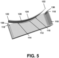
Figure 5 is a cross sectional view of a base portion and a lid portion while the lid portion is being removed. -
Figure 6 is a perspective view of a base portion and lid portion in various stages of installing and removing the lid portion. -
Figure 7 is a perspective view a portion of a side of a base portion having alternative side supports. -
Figure 8 is a perspective view a portion of a side of a base portion having alternative side supports. -
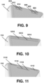
Figure 9 is a perspective view a portion of an end of a base portion having alternative end support protrusions. -
Figure 10 is a perspective view a portion of an end of a base portion having alternative end support protrusions. -
Figure 11 is a perspective view a portion of an end of a base portion having alternative end support protrusions. -
Figure 12 is a perspective view a portion of an end of a base portion having an end support slot. -
Figure 13 is a cut away of the perspective view ofFigure 12 . -
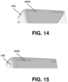
Figure 14 is a perspective view a portion of an end of a base portion having alternative end support slots. -
Figure 15 is a cut away of the perspective view ofFigure 14 . -
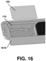
Figure 16 is a perspective view of a container capable of housing the base portion and lid portion of the embodiments of the present disclosure. - The present disclosure provides a container comprising: a base portion, the base portion having: at least one side support; and at least one end support at each end of the base portion; and a flexible, resilient lid portion, the lid portion configured to be installed to the base portion utilizing the resilience in the lid portion for inserting each end of the lid portion into the at least one end support.
- The present disclosure further provides a container comprising: a base portion, the base portion having: a side support at each side of the container; and an end support at each end of the base portion; and a flexible, resilient lid portion, the lid portion configured to be installed to the base portion utilizing the resilience in the lid portion for inserting each end of the lid portion into a respective end support.
- The present disclosure further provides a method for installing a flexible, resilient lid to a container, the container comprising a base portion having a side support at each side of the container and an end support at each end of the base portion, the method comprising: bending the lid by applying pressure to each end of the lid; aligning the lid with each end support; and releasing the lid, wherein the lid re-forms into a flat lid within the end supports.
- Components under a cover or insider a container may need to occasional be accessed. For example, a cover may be placed over a printed circuit board or over the sensitive electronics within a commercial product to protect such electronics. However, in order to access the electronics within such cover, a lid for the cover may need to be removed.
- Typically, covers for printed circuit boards include a lid that is secured to a base utilizing screws. However, such screws add a cost to the cover, both in terms of material costs and installation costs. Further, screws require screw bosses within the cover. The screw bosses take additional space away from the PCB and inside the product.
- Other securing mechanisms, such as clasps, hinges, or the like further add material and installation costs.
- In other embodiments, a protective casing may be placed around alarms or firefighting equipment. Such alarms or firefighting equipment may occasionally need to be serviced and the protective casing may make the equipment therein difficult to access.
- In this regard, in accordance with the embodiments of the present disclosure a lid and base combination is provided which allows a simple, cost-effective solution to install and open the lid. The present disclosure is not limited to any particular use for a container. While the present disclosure is provided with regard to a container that can be mounted over a printed circuit board, the present disclosure is not limited to such functionality.
- Reference is now made to the drawings, in which like reference numerals are used throughout the drawing figures. As seen in
Figure 1 , a container includes abase portion 110 and alid portion 120. -
Base portion 110 may be any container or cover for an application, and in this regard may be shaped and configured based on such application. In particular,base portion 110 may include abottom 111 in some cases. However, in other cases where the base portion is mounted directly to the printed circuit board or to another container or surface, it may not require a bottom portion. Therefore,bottom portion 111 is optional. - In the example of
Figure 1 ,base portion 110 is substantially rectangular in shape. However, in other embodiments, different shapes could be used forbase portion 110. For example,base portion 110 may have more than four sides. The embodiments of the present disclosure would equally work with, for example, a hexagon shapedbase portion 110. In other cases,base portion 110 may have rounded ends. In other cases,base portion 110 may have more than four sides. - In the embodiments of the present disclosure,
base portion 110 includes at least oneside support member 112. Typically,base portion 110 would include twoside support members 112, opposite each other. The side support members are described in more detail below. -
Base portion 110 further includes anend support member 118 at each end thereof.End support member 118 is configured to allow installation of thelid portion 120 and to hold the lid portion to thebase portion 110. Theend support member 118 is described in more detail below. - The
lid portion 120 is comprised of any flexible, resilient material that allowslid portion 120 to be bent with pressure at theends 122 of thelid portion 120, and then to spring back to the substantially flat configuration once the pressure at ends 122 is removed. - Referring to
Figure 2 ,base portion 110 is provided. In the example ofFigure 2 ,end support member 118 includes a lower protrusion and upper protrusion. - Further,
side support member 112 includes a raisedsurface 114 and a raisedsurface 116. In practice, the raisedsurface 114, raisedsurface 116 and the lower protrusion ofend support member 118 are coplanar. - Further,
side support member 112 extends downwardly into thebase portion 110 from the raisedsurfaces side support member 112. This central dip can, in practice, provide support for when pressure is placed onto acentral part 124 of thelid portion 120 to prevent thelid portion 120 from contacting the contents ofbase portion 110 or from warping thelid portion 120 too much, thereby potentiallydamaging lid portion 120. - Referring to
Figures 3 and 4 , installation oflid portion 120 may be accomplished by adding pressure to theends 122 oflid portion 120 in order to bend thelid portion 120. As seen inFigure 4 , theend support member 118 includes aupper protrusion 130 and alower protrusion 132. In this regard, for installation, thelid portion 120 must be bent sufficiently to allow theends 122 to clear theupper protrusion 130 but still engage thelower protrusion 132. Thereafter, the lid may be released, as seen inFigure 4 , in which case the resilience of thelid portion 120 causes the lid to re-form into a substantially flat lid portion. In this case, theends 122 oflid portion 120 fit between theupper protrusion 130 and thelower protrusion 132 at each end of the base, thereby holding thelid portion 122 in place. As such, thebase portion 110 could be rotated, vibrated or displaced and thelid portion 122 would remain in place. - As seen in
Figure 4 , when thelid portion 120 is in the substantially flat configuration, it may rest on the raisedsurfaces lid portion 120. - Referring to
Figure 5 , in order to remove thelid portion 120, pressure may be applied to acentral part 124 of thelid portion 120. In this regard,side support member 112 is configured to allow for thelid portion 120 to bend sufficiently to allow theends 122 to clear theupper protrusion 130 on at least one end of thebase portion 110. Specifically, the spacing between the raisedsurfaces side portion 112 may be configured to allow for thelid portion 120 to have sufficient bend to clear suchupper protrusion 130 when pressure is applied tocentral part 124 oflid portion 120. - Once the
lid portion 120 is bent and at least one of theend portions 122 has cleared theupper protrusion 130, the lid may be removed from thebase portion 110, thereby allowing access to the contents of abase portion 110. - Reference is now made to
Figure 6 , which shows the process for the installation and removal of thelid portion 120 onto the base portion and from thebase portion 110. Specifically, as seen inFigure 6 , at afirst stage 610, thelid portion 120 is separate from the base of aportion 110. Pressure may be applied to each end oflid portion 120 as seen insecond stage 620 in order to situate the lid in the appropriate position for engagement with theend support member 118. - The pressure may then be released as seen at
stage 630, where the container is closed and thelid portion 120 is secured to thebase portion 110. In particular, the resilience oflid portion 120 causes thelid portion 120 to assume a substantially flat shape and engage the end supports of thebase portion 110. Further, support for the sides of thelid portion 120 may be accomplished through one or more side supports. - In this regard, installation may be accomplished without use of any mechanical fasteners being added to the lid. An assembler does not need to screw
lid portion 120 tobase portion 110, saving costs in both materials and installation time. - Thereafter, as seen at
stage 640, pressure may be applied to acentral part 124 of thelid portion 120 in order to bend thelid portion 120 and disengage from theend members 118. Thereafter, the lid may be removed from thebase portion 110 to allow access to the contents within thebase portion 110. - While the embodiments of
Figures 1 to 5 show aside support 112 having raisedsurfaces surfaces - In particular, reference is now made to
Figure 7 . In the embodiment ofFigure 7 , rather than aside portion 112, pegs 710 may be provided on one or both sides of abase portion 110.Pegs 710 may be located on the same plane as the base of theend support 118 and provide for support for thelid portion 120 once thelid portion 120 is in its flat, closed configuration. In the example ofFigure 7 , pegs 710 may protrude sufficiently to provide support without impinging too much intobase portion 110. - Another option is provided with regard to
Figure 8 . In particular, inFigure 8 , pegs 810 may be provided at one or both sides of thebase portion 110.Pegs 810 are configured differently frompegs 710 ofFigure 7 . Specifically, pegs 810 are elongate, which may provide more structure to such pegs, thereby avoiding the peg from breaking away frombase portion 110 in some embodiments. - While the embodiments of
Figures 7 and 8 provide an alternative toside support 112, this is not meant to be limiting. Other types of supports could equally be used with the embodiments of the present disclosure. In particular, any supports in which the pegs or side supports are spaced sufficiently apart from each other to allow for thelid portion 120 to be bent along acentral part 124 into the container for removal of the lid portion would be suitable. Further, such pegs may provide a pivot point for the lid portion to ensure the disengagement of the lid portion from the end supports. - Further, in some embodiments, fewer or more supports could be provided at the sides. Specifically, in some cases it may be sufficient to have only one peg or side support on one side or both sides of the
base portion 110. If only one side support exists on a side of the base portion, typically such support would be displaced away from thecentral part 124 of thelid portion 120 to allow such lid portion to be bent. - Further, in some embodiments, a different number of supports or different configuration of supports could be used on the sides of
base portion 110. Specifically, in some cases theside support 112 could be used on a first side of thebase portion 110 and pegs such as those described with regard toFigures 7 and 8 could be used on a second side of thebase portion 110. In other cases, a single peg may be used on one side of thebase portion 110 and two or more pegs could be used on a second side of thebase portion 110. Other options are possible. - In addition to the side supports, the end supports may also vary. Reference is now made to
Figures 9 to 15 . - In some embodiments, the end supports may be broken at an end of
base portion 110. For example, in the embodiment ofFigure 9 , an end ofbase portion 110 may include afirst end support 910 and a second andsupport 920. Thefirst end support 910 includes anupper protrusion 912 and alower protrusion 914.Second end support 920 includes anupper protrusion 922 and alower protrusion 924. While the embodiment ofFigure 9 includes only two end supports, in other embodiments, a plurality of end supports could be provided along an end ofbase portion 110. - Referring to
Figure 10 , asingle end support 1010 can extend along an end ofbase portion 110.End support 1010 can include anupper protrusion 1012 and alower protrusion 1014. In some embodiments,end support 1010 can extend along an entire end ofbase support 110. In other cases, theend support 1010 could be shorter. In some cases,base support 1010 is centred between the sides and along an end of abase portion 110. - Referring to a
Figure 11 , anend support 1110 could include a plurality ofupper protrusions 1112 and a singlelower protrusion 1114, where theupper protrusions 1112 and thelower protrusion 1114 are staggered along the end ofbase portion 110. In other cases, a singleupper protrusion 1110 and a plurality oflower protrusions 1114 could exist. In other cases, both a plurality ofupper protrusions 1112 and a plurality oflower protrusions 1114 could exist along an end ofbase portion 110. - Referring to
Figures 12 and 13 , rather than protrusions, a slot may exist within an end ofbase portion 110. In particular,Figure 13 is a cutaway portion of the embodiment ofFigure 12 and shows an indent or slot in an end ofbase portion 110.Slot 1210 could accommodate an end oflid portion 120. In particular,slot 1210 may, in some embodiments, extend the length of the end of thebase portion 110, thereby allowing alid portion 120 to fit therein. - In other embodiments, the
slot 1210 may be shorter than the end of thebase portion 110, in which case thelid portion 120 may be configured to have anend 122 dimensioned to fit within theslot 1210. This may involve, for example, cutting away the corners oflid portion 120 to allow the ends oflid portion 120 to fit withinslot 1210. - Referring to
Figures 14 and 15 , in some embodiments a plurality ofslots 1410 may exist in an end ofbase portion 110. The embodiment ofFigure 15 is a cutaway of the embodiment ofFigure 14 showing a cutaway of oneslot 1410. - While the embodiments of
Figures 14 and 15 show twoslots 1410, in other embodiments more slots may be provided at the end ofbase portion 110. -
Lid portion 120 would have anend 122 dimensioned to fit within theslots 1410 at each end of thebase portion 110. - Further, in some embodiments, the end portions described with regard to
Figures 9 to 15 could be combined. Specifically, in some cases, a first end ofbase portion 110 could have protrusions or slots as described with regard toFigures 9 to 15 , and a second end ofbase portion 110 could have different protrusions or slots as described with regard toFigures 9 to 15 . - In practice, the
base portion 110 andlid portion 120 may be standalone containers, or may fit within another product. For example, referring toFigure 16 , acontainer 1610 may be used for mounting electronics and components to a shipping container. Abase portion 110 may be used to house a printed circuit board and electronics and alid portion 120 may fit thereon. Other parts ofcontainer 1610 may be used for other components such as sensors, input and output devices, or other such components. - Therefore, the embodiment of
Figure 16 shows one case in which the base and lid portions of the present disclosure may be utilized. However, as would be appreciated by those skilled in the art, thebase portion 110 andlid portion 120 could be used in many other scenarios. - Based on the embodiments of
Figures 1 to 16 , a push to open lid and base are provided which allow for easy, cost effective closing of the base portion while allowing for easy access subsequent to such closing to the contents of the base portion. - The embodiments described herein are examples of structures, systems or methods having elements corresponding to elements of the techniques of this application. This written description may enable those skilled in the art to make and use embodiments having alternative elements that likewise correspond to the elements of the techniques of this application. The intended scope of the techniques of this application thus includes other structures, systems or methods that do not differ from the techniques of this application as described herein, and further includes other structures, systems or methods with insubstantial differences from the techniques of this application as described herein.
- Also, techniques, systems, subsystems, and methods described and illustrated in the various implementations as discrete or separate may be combined or integrated with other systems, modules, techniques, or methods. Other items shown or discussed as coupled or directly coupled or communicating with each other may be indirectly coupled or communicating through some interface, device, or intermediate component, whether electrically, mechanically, or otherwise. Other examples of changes, substitutions, and alterations are ascertainable by one skilled in the art and may be made.
- While the above detailed description has shown, described, and pointed out the fundamental novel features of the disclosure as applied to various implementations, it will be understood that various omissions, substitutions, and changes in the form and details of the system illustrated may be made by those skilled in the art.
- Furthermore, the present disclosure includes the following enumerated clauses:
- 1. A container comprising:
- a base portion, the base portion having:
- at least one side support; and
- at least one end support at each end of the base portion; and
- a flexible, resilient lid portion, the lid portion configured to be installed to the base portion utilizing the resilience in the lid portion for inserting each end of the lid portion into the at least one end support.
- a base portion, the base portion having:
- 2. The container of enumerated clause 1, wherein the at least one side support may comprise:
- a first raised support connected to an inner part of the base portion;
- a second raised support connected to an inner part of the base portion; and
- a central portion displaced further away from an opening of the base portion than the first raised portion and the second raised support.
- 3. The container of enumerated clause 2, wherein the central portion may prevent a central part of the lid from being pushed further into the base portion than the central portion when disengaging the lid portion.
- 4. The container of enumerated clause 1, wherein the at least one side support may comprise a pair of pegs protruding into the base portion.
- 5. The container of enumerated clause 4, wherein the pair of pegs may be spaced to allow a central part of the lid portion to flex therebetween.
- 6. The container of enumerated clause 1, wherein the container may include two side supports, and wherein a first side support on one side of the base portion may differ from a second side support at a second side of the base portion.
- 7. The container of enumerated clause 1, wherein the at least one end support may comprise at least one upper protrusion and at least one lower protrusion extending from the end of the base portion.
- 8. The container of enumerated clause 7, wherein the at least one lower protrusion may extend into the base portion more than the at least one upper protrusion.
- 9. The container of enumerated clause 7, wherein the at least one upper protrusion may be staggered from the at least one lower protrusion at an end of the base portion.
- 10. The container of enumerated clause 1, the at least one end support may comprise at least one slot at the end of the base portion.
- 11. The container of enumerated clause 1, wherein the container may include two end supports, and wherein a first end support on one end of the base portion differs from a second end support at a second end of the base portion.
- 12. A container comprising:
- a base portion, the base portion having:
- a side support at each side of the container; and
- an end support at each end of the base portion; and
- a flexible, resilient lid portion, the lid portion configured to be installed to the base portion utilizing the resilience in the lid portion for inserting each end of the lid portion into a respective end support.
- a base portion, the base portion having:
- 13. The container of enumerated clause 12, wherein each side support may comprise:
- a first raised support connected to an inner part of the base portion;
- a second raised support connected to an inner part of the base portion; and
- a central portion displaced further away from an opening of the base portion than the first raised portion and the second raised support.
- 14. The container of enumerated clause 13, wherein the central portion may prevent a central part of the lid from being pushed further into the base portion than the central portion when disengaging the lid portion.
- 15. The container of enumerated clause 13, wherein the at least one side support may comprise a pair of pegs protruding into the base portion.
- 16. The container of enumerated clause 15, wherein the pair of pegs may be spaced to allow a central part of the lid portion to flex therebetween.
- 17. The container of enumerated clause 13, wherein each end support may comprise at least one upper protrusion and at least one lower protrusion extending from the end of the base portion.
- 18. The container of enumerated clause 17, wherein the at least one lower protrusion may extend into the base portion more than the at least one upper protrusion.
- 19. A method for installing a flexible, resilient lid to a container, the container comprising a base portion having a side support at each side of the container and an end support at each end of the base portion, the method comprising:
- bending the lid by applying pressure to each end of the lid;
- aligning the lid with each end support; and
- releasing the lid,
- 20. The method of enumerated clause 19, wherein the lid may rest on each side support when it re-forms into the flat lid.
- 21. The method of enumerated clause 19, optionally further comprising removing the lid, the removing comprising:
- applying pressure to a central part of the lid to bend the lid between the side supports until an end of the lid disengages from the end support; and
- removing the lid.
- In the foregoing description, numerous details are set forth to provide an understanding of the subject disclosed herein. However, implementations may be practiced without some of these details. Other implementations may include modifications and variations from the details discussed above. It is intended that the appended claims cover such modifications and variations.
Claims (15)
- A container comprising:a base portion, the base portion having:at least one side support; andat least one end support at each end of the base portion; anda flexible, resilient lid portion, the lid portion configured to be installed to the base portion utilizing the resilience in the lid portion for inserting each end of the lid portion into the at least one end support.
- The container of claim 1, wherein the at least one side support comprises:a first raised support connected to an inner part of the base portion;a second raised support connected to an inner part of the base portion; anda central portion displaced further away from an opening of the base portion than the first raised portion and the second raised support, wherein optionally the central portion prevents a central part of the lid from being pushed further into the base portion than the central portion when disengaging the lid portion.
- The container of claim 1 or 2, wherein the at least one side support comprises a pair of pegs protruding into the base portion, wherein optionally the pair of pegs is spaced to allow a central part of the lid portion to flex therebetween.
- The container of any of claims 1 to 3, wherein the container includes two side supports, and wherein a first side support on one side of the base portion differs from a second side support at a second side of the base portion.
- The container of any of claims 1 to 4, wherein the at least one end support comprises at least one upper protrusion and at least one lower protrusion extending from the end of the base portion.
- The container of claim 5, wherein the at least one lower protrusion extends into the base portion more than the at least one upper protrusion and/or wherein the at least one upper protrusion is staggered from the at least one lower protrusion at an end of the base portion.
- The container of any of claims 1 to 6, the at least one end support comprises at least one slot at the end of the base portion.
- The container of any of claims 1 to 7, wherein the container includes two end supports, and wherein a first end support on one end of the base portion differs from a second end support at a second end of the base portion.
- A container comprising:a base portion, the base portion having:a side support at each side of the container; andan end support at each end of the base portion; anda flexible, resilient lid portion, the lid portion configured to be installed to the base portion utilizing the resilience in the lid portion for inserting each end of the lid portion into a respective end support.
- The container of claim 9, wherein each side support comprises:a first raised support connected to an inner part of the base portion;a second raised support connected to an inner part of the base portion; anda central portion displaced further away from an opening of the base portion than the first raised portion and the second raised support.
- The container of claim 10, wherein the central portion prevents a central part of the lid from being pushed further into the base portion than the central portion when disengaging the lid portion.
- The container of claim 10 or 11, wherein at least one of the side support comprises a pair of pegs protruding into the base portion.
- The container of claim 12, wherein the pair of pegs is spaced to allow a central part of the lid portion to flex therebetween.
- The container of any of claims 10 to 13, wherein each end support comprises at least one upper protrusion and at least one lower protrusion extending from the end of the base portion.
- The container of claim 14, wherein the at least one lower protrusion extends into the base portion more than the at least one upper protrusion.
Applications Claiming Priority (1)
| Application Number | Priority Date | Filing Date | Title |
|---|---|---|---|
| US17/516,020 US11985769B2 (en) | 2021-11-01 | 2021-11-01 | Push-to-open lid and container |
Publications (2)
| Publication Number | Publication Date |
|---|---|
| EP4175427A1 true EP4175427A1 (en) | 2023-05-03 |
| EP4175427B1 EP4175427B1 (en) | 2025-06-25 |
Family
ID=84044849
Family Applications (1)
| Application Number | Title | Priority Date | Filing Date |
|---|---|---|---|
| EP22204295.4A Active EP4175427B1 (en) | 2021-11-01 | 2022-10-28 | A push-to-open lid and container |
Country Status (3)
| Country | Link |
|---|---|
| US (1) | US11985769B2 (en) |
| EP (1) | EP4175427B1 (en) |
| CA (1) | CA3173573A1 (en) |
Citations (6)
| Publication number | Priority date | Publication date | Assignee | Title |
|---|---|---|---|---|
| GB704190A (en) * | 1951-09-18 | 1954-02-17 | Dunlop Rubber Co | Closure members for pressure containers |
| US3360161A (en) * | 1965-10-21 | 1967-12-26 | Marlin B Smith | Splashproof drinking vessel |
| US4090636A (en) * | 1977-08-22 | 1978-05-23 | B.W. Norton Manufacturing Co. Inc. | Metal paint pail cover |
| JPS6092959U (en) * | 1983-11-30 | 1985-06-25 | 積水化成品工業株式会社 | container |
| KR100656399B1 (en) * | 2005-06-28 | 2006-12-13 | 엘지전자 주식회사 | Hook coupling structure and case using the same |
| US20110222212A1 (en) * | 2010-03-11 | 2011-09-15 | Hong Fu Jin Precision Industry (Shenzhen) Co., Ltd. | Electronic device with latching mechanism |
Family Cites Families (3)
| Publication number | Priority date | Publication date | Assignee | Title |
|---|---|---|---|---|
| GB190202498A (en) | 1902-01-30 | 1903-01-22 | John Douglas Palmer | Improvements in Casings for Electrical Conductors, Gas and Water Pipes, and the like. |
| US982436A (en) | 1906-03-30 | 1911-01-24 | Settimio Maggiorani | Lid for boxes, cases, &c. |
| US20130327770A1 (en) * | 2012-06-07 | 2013-12-12 | Robert R. Turvey | Container having an arched portion and Lid Therefor |
-
2021
- 2021-11-01 US US17/516,020 patent/US11985769B2/en active Active
-
2022
- 2022-09-08 CA CA3173573A patent/CA3173573A1/en active Pending
- 2022-10-28 EP EP22204295.4A patent/EP4175427B1/en active Active
Patent Citations (6)
| Publication number | Priority date | Publication date | Assignee | Title |
|---|---|---|---|---|
| GB704190A (en) * | 1951-09-18 | 1954-02-17 | Dunlop Rubber Co | Closure members for pressure containers |
| US3360161A (en) * | 1965-10-21 | 1967-12-26 | Marlin B Smith | Splashproof drinking vessel |
| US4090636A (en) * | 1977-08-22 | 1978-05-23 | B.W. Norton Manufacturing Co. Inc. | Metal paint pail cover |
| JPS6092959U (en) * | 1983-11-30 | 1985-06-25 | 積水化成品工業株式会社 | container |
| KR100656399B1 (en) * | 2005-06-28 | 2006-12-13 | 엘지전자 주식회사 | Hook coupling structure and case using the same |
| US20110222212A1 (en) * | 2010-03-11 | 2011-09-15 | Hong Fu Jin Precision Industry (Shenzhen) Co., Ltd. | Electronic device with latching mechanism |
Also Published As
| Publication number | Publication date |
|---|---|
| US11985769B2 (en) | 2024-05-14 |
| CA3173573A1 (en) | 2023-05-01 |
| US20230136400A1 (en) | 2023-05-04 |
| EP4175427B1 (en) | 2025-06-25 |
Similar Documents
| Publication | Publication Date | Title |
|---|---|---|
| US6771512B2 (en) | Mounting system for circuit board | |
| US7855898B2 (en) | Expansion card retention assembly | |
| US4585122A (en) | Secure housing arrangement for electronic apparatus | |
| US5680293A (en) | Screwless hard drive mounting in a computer system with a chassis via a first bracket rigidly mounted to the chassis and a second bracket movably mounted to the chassis | |
| US6438800B1 (en) | Door hinge assembly for an electrical appliance enclosure | |
| US5354951A (en) | Circuit board component shielding enclosure and assembly | |
| US7715209B2 (en) | Expansion card retention assembly | |
| US6834766B2 (en) | Expansion card mounting apparatus | |
| JP3638535B2 (en) | Card holding assembly and chassis using the same | |
| US4215796A (en) | Radio frequency shield structure | |
| US5999402A (en) | Heat sink fastener retention apparatus and method for computer systems | |
| US6700791B1 (en) | Computer expansion card retainer assembly | |
| US7576999B2 (en) | Expansion card retention assembly | |
| US7593238B2 (en) | Expansion card retention assembly | |
| EP3368811B1 (en) | Wall mounted electronic device and corresponding method for mounting | |
| US11985769B2 (en) | Push-to-open lid and container | |
| CN104181997A (en) | Electronic device shell | |
| US10368459B2 (en) | Equipment clamping assembly using clamps and friction to secure equipment for use in rugged and other environments | |
| US20060268514A1 (en) | Mounting apparatus for fan | |
| US9253900B2 (en) | Hardware casing with spring loaded friction fitting cover | |
| US5074727A (en) | Threaded device retainer | |
| HK40092367B (en) | A push-to-open lid and container | |
| HK40092367A (en) | A push-to-open lid and container | |
| US5820171A (en) | Option card slot filler plate | |
| US20070030660A1 (en) | Retention device for mounting expansion cards |
Legal Events
| Date | Code | Title | Description |
|---|---|---|---|
| PUAI | Public reference made under article 153(3) epc to a published international application that has entered the european phase |
Free format text: ORIGINAL CODE: 0009012 |
|
| STAA | Information on the status of an ep patent application or granted ep patent |
Free format text: STATUS: THE APPLICATION HAS BEEN PUBLISHED |
|
| AK | Designated contracting states |
Kind code of ref document: A1 Designated state(s): AL AT BE BG CH CY CZ DE DK EE ES FI FR GB GR HR HU IE IS IT LI LT LU LV MC ME MK MT NL NO PL PT RO RS SE SI SK SM TR |
|
| P01 | Opt-out of the competence of the unified patent court (upc) registered |
Effective date: 20230518 |
|
| STAA | Information on the status of an ep patent application or granted ep patent |
Free format text: STATUS: REQUEST FOR EXAMINATION WAS MADE |
|
| 17P | Request for examination filed |
Effective date: 20231024 |
|
| RBV | Designated contracting states (corrected) |
Designated state(s): AL AT BE BG CH CY CZ DE DK EE ES FI FR GB GR HR HU IE IS IT LI LT LU LV MC ME MK MT NL NO PL PT RO RS SE SI SK SM TR |
|
| REG | Reference to a national code |
Ref country code: HK Ref legal event code: DE Ref document number: 40092367 Country of ref document: HK |
|
| GRAP | Despatch of communication of intention to grant a patent |
Free format text: ORIGINAL CODE: EPIDOSNIGR1 |
|
| STAA | Information on the status of an ep patent application or granted ep patent |
Free format text: STATUS: GRANT OF PATENT IS INTENDED |
|
| INTG | Intention to grant announced |
Effective date: 20240909 |
|
| GRAJ | Information related to disapproval of communication of intention to grant by the applicant or resumption of examination proceedings by the epo deleted |
Free format text: ORIGINAL CODE: EPIDOSDIGR1 |
|
| STAA | Information on the status of an ep patent application or granted ep patent |
Free format text: STATUS: REQUEST FOR EXAMINATION WAS MADE |
|
| REG | Reference to a national code |
Ref country code: DE Ref legal event code: R079 Free format text: PREVIOUS MAIN CLASS: H05K0005000000 Ipc: H05K0005150000 Ref document number: 602022016384 Country of ref document: DE |
|
| GRAS | Grant fee paid |
Free format text: ORIGINAL CODE: EPIDOSNIGR3 |
|
| STAA | Information on the status of an ep patent application or granted ep patent |
Free format text: STATUS: GRANT OF PATENT IS INTENDED |
|
| GRAP | Despatch of communication of intention to grant a patent |
Free format text: ORIGINAL CODE: EPIDOSNIGR1 |
|
| INTC | Intention to grant announced (deleted) | ||
| RIC1 | Information provided on ipc code assigned before grant |
Ipc: H05K 5/15 20250101AFI20250115BHEP |
|
| INTG | Intention to grant announced |
Effective date: 20250122 |
|
| GRAA | (expected) grant |
Free format text: ORIGINAL CODE: 0009210 |
|
| STAA | Information on the status of an ep patent application or granted ep patent |
Free format text: STATUS: THE PATENT HAS BEEN GRANTED |
|
| AK | Designated contracting states |
Kind code of ref document: B1 Designated state(s): AL AT BE BG CH CY CZ DE DK EE ES FI FR GB GR HR HU IE IS IT LI LT LU LV MC ME MK MT NL NO PL PT RO RS SE SI SK SM TR |
|
| REG | Reference to a national code |
Ref country code: GB Ref legal event code: FG4D |
|
| REG | Reference to a national code |
Ref country code: CH Ref legal event code: EP |
|
| REG | Reference to a national code |
Ref country code: CH Ref legal event code: EP |
|
| REG | Reference to a national code |
Ref country code: IE Ref legal event code: FG4D |
|
| REG | Reference to a national code |
Ref country code: DE Ref legal event code: R096 Ref document number: 602022016384 Country of ref document: DE |
|
| PG25 | Lapsed in a contracting state [announced via postgrant information from national office to epo] |
Ref country code: FI Free format text: LAPSE BECAUSE OF FAILURE TO SUBMIT A TRANSLATION OF THE DESCRIPTION OR TO PAY THE FEE WITHIN THE PRESCRIBED TIME-LIMIT Effective date: 20250625 |
|
| REG | Reference to a national code |
Ref country code: LT Ref legal event code: MG9D |
|
| PG25 | Lapsed in a contracting state [announced via postgrant information from national office to epo] |
Ref country code: NO Free format text: LAPSE BECAUSE OF FAILURE TO SUBMIT A TRANSLATION OF THE DESCRIPTION OR TO PAY THE FEE WITHIN THE PRESCRIBED TIME-LIMIT Effective date: 20250925 Ref country code: GR Free format text: LAPSE BECAUSE OF FAILURE TO SUBMIT A TRANSLATION OF THE DESCRIPTION OR TO PAY THE FEE WITHIN THE PRESCRIBED TIME-LIMIT Effective date: 20250926 |
|
| PG25 | Lapsed in a contracting state [announced via postgrant information from national office to epo] |
Ref country code: BG Free format text: LAPSE BECAUSE OF FAILURE TO SUBMIT A TRANSLATION OF THE DESCRIPTION OR TO PAY THE FEE WITHIN THE PRESCRIBED TIME-LIMIT Effective date: 20250625 |
|
| PG25 | Lapsed in a contracting state [announced via postgrant information from national office to epo] |
Ref country code: HR Free format text: LAPSE BECAUSE OF FAILURE TO SUBMIT A TRANSLATION OF THE DESCRIPTION OR TO PAY THE FEE WITHIN THE PRESCRIBED TIME-LIMIT Effective date: 20250625 |
|
| PG25 | Lapsed in a contracting state [announced via postgrant information from national office to epo] |
Ref country code: RS Free format text: LAPSE BECAUSE OF FAILURE TO SUBMIT A TRANSLATION OF THE DESCRIPTION OR TO PAY THE FEE WITHIN THE PRESCRIBED TIME-LIMIT Effective date: 20250925 |
|
| PG25 | Lapsed in a contracting state [announced via postgrant information from national office to epo] |
Ref country code: LV Free format text: LAPSE BECAUSE OF FAILURE TO SUBMIT A TRANSLATION OF THE DESCRIPTION OR TO PAY THE FEE WITHIN THE PRESCRIBED TIME-LIMIT Effective date: 20250625 |
|
| REG | Reference to a national code |
Ref country code: NL Ref legal event code: MP Effective date: 20250625 |
|
| PG25 | Lapsed in a contracting state [announced via postgrant information from national office to epo] |
Ref country code: NL Free format text: LAPSE BECAUSE OF FAILURE TO SUBMIT A TRANSLATION OF THE DESCRIPTION OR TO PAY THE FEE WITHIN THE PRESCRIBED TIME-LIMIT Effective date: 20250625 |
|
| PG25 | Lapsed in a contracting state [announced via postgrant information from national office to epo] |
Ref country code: PT Free format text: LAPSE BECAUSE OF FAILURE TO SUBMIT A TRANSLATION OF THE DESCRIPTION OR TO PAY THE FEE WITHIN THE PRESCRIBED TIME-LIMIT Effective date: 20251027 |
|
| REG | Reference to a national code |
Ref country code: AT Ref legal event code: MK05 Ref document number: 1808052 Country of ref document: AT Kind code of ref document: T Effective date: 20250625 |
|
| PG25 | Lapsed in a contracting state [announced via postgrant information from national office to epo] |
Ref country code: IS Free format text: LAPSE BECAUSE OF FAILURE TO SUBMIT A TRANSLATION OF THE DESCRIPTION OR TO PAY THE FEE WITHIN THE PRESCRIBED TIME-LIMIT Effective date: 20251025 |
|
| PGFP | Annual fee paid to national office [announced via postgrant information from national office to epo] |
Ref country code: DE Payment date: 20251020 Year of fee payment: 4 |
|
| PG25 | Lapsed in a contracting state [announced via postgrant information from national office to epo] |
Ref country code: AT Free format text: LAPSE BECAUSE OF FAILURE TO SUBMIT A TRANSLATION OF THE DESCRIPTION OR TO PAY THE FEE WITHIN THE PRESCRIBED TIME-LIMIT Effective date: 20250625 Ref country code: SM Free format text: LAPSE BECAUSE OF FAILURE TO SUBMIT A TRANSLATION OF THE DESCRIPTION OR TO PAY THE FEE WITHIN THE PRESCRIBED TIME-LIMIT Effective date: 20250625 |
|
| PGFP | Annual fee paid to national office [announced via postgrant information from national office to epo] |
Ref country code: FR Payment date: 20251029 Year of fee payment: 4 |
|
| PG25 | Lapsed in a contracting state [announced via postgrant information from national office to epo] |
Ref country code: CZ Free format text: LAPSE BECAUSE OF FAILURE TO SUBMIT A TRANSLATION OF THE DESCRIPTION OR TO PAY THE FEE WITHIN THE PRESCRIBED TIME-LIMIT Effective date: 20250625 |
|
| PG25 | Lapsed in a contracting state [announced via postgrant information from national office to epo] |
Ref country code: PL Free format text: LAPSE BECAUSE OF FAILURE TO SUBMIT A TRANSLATION OF THE DESCRIPTION OR TO PAY THE FEE WITHIN THE PRESCRIBED TIME-LIMIT Effective date: 20250625 |
|
| PG25 | Lapsed in a contracting state [announced via postgrant information from national office to epo] |
Ref country code: EE Free format text: LAPSE BECAUSE OF FAILURE TO SUBMIT A TRANSLATION OF THE DESCRIPTION OR TO PAY THE FEE WITHIN THE PRESCRIBED TIME-LIMIT Effective date: 20250625 |
|
| PG25 | Lapsed in a contracting state [announced via postgrant information from national office to epo] |
Ref country code: SK Free format text: LAPSE BECAUSE OF FAILURE TO SUBMIT A TRANSLATION OF THE DESCRIPTION OR TO PAY THE FEE WITHIN THE PRESCRIBED TIME-LIMIT Effective date: 20250625 |
|
| PG25 | Lapsed in a contracting state [announced via postgrant information from national office to epo] |
Ref country code: ES Free format text: LAPSE BECAUSE OF FAILURE TO SUBMIT A TRANSLATION OF THE DESCRIPTION OR TO PAY THE FEE WITHIN THE PRESCRIBED TIME-LIMIT Effective date: 20250625 |
|
| PG25 | Lapsed in a contracting state [announced via postgrant information from national office to epo] |
Ref country code: RO Free format text: LAPSE BECAUSE OF FAILURE TO SUBMIT A TRANSLATION OF THE DESCRIPTION OR TO PAY THE FEE WITHIN THE PRESCRIBED TIME-LIMIT Effective date: 20250625 |
|
| PG25 | Lapsed in a contracting state [announced via postgrant information from national office to epo] |
Ref country code: DK Free format text: LAPSE BECAUSE OF FAILURE TO SUBMIT A TRANSLATION OF THE DESCRIPTION OR TO PAY THE FEE WITHIN THE PRESCRIBED TIME-LIMIT Effective date: 20250625 |
|
| PG25 | Lapsed in a contracting state [announced via postgrant information from national office to epo] |
Ref country code: IT Free format text: LAPSE BECAUSE OF FAILURE TO SUBMIT A TRANSLATION OF THE DESCRIPTION OR TO PAY THE FEE WITHIN THE PRESCRIBED TIME-LIMIT Effective date: 20250625 |
|
| PLBE | No opposition filed within time limit |
Free format text: ORIGINAL CODE: 0009261 |
|
| STAA | Information on the status of an ep patent application or granted ep patent |
Free format text: STATUS: NO OPPOSITION FILED WITHIN TIME LIMIT |
|
| REG | Reference to a national code |
Ref country code: CH Ref legal event code: L10 Free format text: ST27 STATUS EVENT CODE: U-0-0-L10-L00 (AS PROVIDED BY THE NATIONAL OFFICE) Effective date: 20260507 |