EP4175375A1 - Positioning method and apparatus - Google Patents
Positioning method and apparatus Download PDFInfo
- Publication number
- EP4175375A1 EP4175375A1 EP21832245.1A EP21832245A EP4175375A1 EP 4175375 A1 EP4175375 A1 EP 4175375A1 EP 21832245 A EP21832245 A EP 21832245A EP 4175375 A1 EP4175375 A1 EP 4175375A1
- Authority
- EP
- European Patent Office
- Prior art keywords
- positioning
- downlink
- uplink
- terminal
- positioning measurement
- Prior art date
- Legal status (The legal status is an assumption and is not a legal conclusion. Google has not performed a legal analysis and makes no representation as to the accuracy of the status listed.)
- Pending
Links
- 238000000034 method Methods 0.000 title claims abstract description 297
- 238000005259 measurement Methods 0.000 claims abstract description 615
- 230000015654 memory Effects 0.000 claims description 65
- 238000012545 processing Methods 0.000 claims description 63
- 238000004364 calculation method Methods 0.000 claims description 33
- 230000006870 function Effects 0.000 claims description 19
- 238000007726 management method Methods 0.000 claims description 17
- 238000005516 engineering process Methods 0.000 claims description 6
- 238000012937 correction Methods 0.000 claims description 5
- 230000011664 signaling Effects 0.000 description 22
- 238000010586 diagram Methods 0.000 description 15
- 238000004590 computer program Methods 0.000 description 8
- 238000004422 calculation algorithm Methods 0.000 description 6
- 238000004891 communication Methods 0.000 description 5
- 238000003672 processing method Methods 0.000 description 4
- 230000003993 interaction Effects 0.000 description 3
- 238000012986 modification Methods 0.000 description 3
- 230000004048 modification Effects 0.000 description 3
- 230000003287 optical effect Effects 0.000 description 3
- 230000005540 biological transmission Effects 0.000 description 2
- 230000001413 cellular effect Effects 0.000 description 2
- 238000006243 chemical reaction Methods 0.000 description 2
- 230000007774 longterm Effects 0.000 description 2
- 238000010295 mobile communication Methods 0.000 description 2
- 230000002093 peripheral effect Effects 0.000 description 2
- 239000003795 chemical substances by application Substances 0.000 description 1
- 238000013500 data storage Methods 0.000 description 1
- 230000000977 initiatory effect Effects 0.000 description 1
- 239000004973 liquid crystal related substance Substances 0.000 description 1
- 238000004519 manufacturing process Methods 0.000 description 1
- 239000004065 semiconductor Substances 0.000 description 1
- 239000007787 solid Substances 0.000 description 1
Images




Classifications
-
- H—ELECTRICITY
- H04—ELECTRIC COMMUNICATION TECHNIQUE
- H04W—WIRELESS COMMUNICATION NETWORKS
- H04W64/00—Locating users or terminals or network equipment for network management purposes, e.g. mobility management
- H04W64/006—Locating users or terminals or network equipment for network management purposes, e.g. mobility management with additional information processing, e.g. for direction or speed determination
-
- H—ELECTRICITY
- H04—ELECTRIC COMMUNICATION TECHNIQUE
- H04W—WIRELESS COMMUNICATION NETWORKS
- H04W64/00—Locating users or terminals or network equipment for network management purposes, e.g. mobility management
-
- G—PHYSICS
- G01—MEASURING; TESTING
- G01S—RADIO DIRECTION-FINDING; RADIO NAVIGATION; DETERMINING DISTANCE OR VELOCITY BY USE OF RADIO WAVES; LOCATING OR PRESENCE-DETECTING BY USE OF THE REFLECTION OR RERADIATION OF RADIO WAVES; ANALOGOUS ARRANGEMENTS USING OTHER WAVES
- G01S5/00—Position-fixing by co-ordinating two or more direction or position line determinations; Position-fixing by co-ordinating two or more distance determinations
- G01S5/0009—Transmission of position information to remote stations
- G01S5/0018—Transmission from mobile station to base station
- G01S5/0036—Transmission from mobile station to base station of measured values, i.e. measurement on mobile and position calculation on base station
-
- G—PHYSICS
- G01—MEASURING; TESTING
- G01S—RADIO DIRECTION-FINDING; RADIO NAVIGATION; DETERMINING DISTANCE OR VELOCITY BY USE OF RADIO WAVES; LOCATING OR PRESENCE-DETECTING BY USE OF THE REFLECTION OR RERADIATION OF RADIO WAVES; ANALOGOUS ARRANGEMENTS USING OTHER WAVES
- G01S5/00—Position-fixing by co-ordinating two or more direction or position line determinations; Position-fixing by co-ordinating two or more distance determinations
- G01S5/02—Position-fixing by co-ordinating two or more direction or position line determinations; Position-fixing by co-ordinating two or more distance determinations using radio waves
- G01S5/0205—Details
- G01S5/021—Calibration, monitoring or correction
-
- G—PHYSICS
- G01—MEASURING; TESTING
- G01S—RADIO DIRECTION-FINDING; RADIO NAVIGATION; DETERMINING DISTANCE OR VELOCITY BY USE OF RADIO WAVES; LOCATING OR PRESENCE-DETECTING BY USE OF THE REFLECTION OR RERADIATION OF RADIO WAVES; ANALOGOUS ARRANGEMENTS USING OTHER WAVES
- G01S5/00—Position-fixing by co-ordinating two or more direction or position line determinations; Position-fixing by co-ordinating two or more distance determinations
- G01S5/02—Position-fixing by co-ordinating two or more direction or position line determinations; Position-fixing by co-ordinating two or more distance determinations using radio waves
- G01S5/0205—Details
- G01S5/0236—Assistance data, e.g. base station almanac
-
- G—PHYSICS
- G01—MEASURING; TESTING
- G01S—RADIO DIRECTION-FINDING; RADIO NAVIGATION; DETERMINING DISTANCE OR VELOCITY BY USE OF RADIO WAVES; LOCATING OR PRESENCE-DETECTING BY USE OF THE REFLECTION OR RERADIATION OF RADIO WAVES; ANALOGOUS ARRANGEMENTS USING OTHER WAVES
- G01S5/00—Position-fixing by co-ordinating two or more direction or position line determinations; Position-fixing by co-ordinating two or more distance determinations
- G01S5/02—Position-fixing by co-ordinating two or more direction or position line determinations; Position-fixing by co-ordinating two or more distance determinations using radio waves
- G01S5/06—Position of source determined by co-ordinating a plurality of position lines defined by path-difference measurements
-
- G—PHYSICS
- G01—MEASURING; TESTING
- G01S—RADIO DIRECTION-FINDING; RADIO NAVIGATION; DETERMINING DISTANCE OR VELOCITY BY USE OF RADIO WAVES; LOCATING OR PRESENCE-DETECTING BY USE OF THE REFLECTION OR RERADIATION OF RADIO WAVES; ANALOGOUS ARRANGEMENTS USING OTHER WAVES
- G01S5/00—Position-fixing by co-ordinating two or more direction or position line determinations; Position-fixing by co-ordinating two or more distance determinations
- G01S5/02—Position-fixing by co-ordinating two or more direction or position line determinations; Position-fixing by co-ordinating two or more distance determinations using radio waves
- G01S5/10—Position of receiver fixed by co-ordinating a plurality of position lines defined by path-difference measurements, e.g. omega or decca systems
-
- H—ELECTRICITY
- H04—ELECTRIC COMMUNICATION TECHNIQUE
- H04L—TRANSMISSION OF DIGITAL INFORMATION, e.g. TELEGRAPHIC COMMUNICATION
- H04L5/00—Arrangements affording multiple use of the transmission path
- H04L5/003—Arrangements for allocating sub-channels of the transmission path
- H04L5/0048—Allocation of pilot signals, i.e. of signals known to the receiver
-
- H—ELECTRICITY
- H04—ELECTRIC COMMUNICATION TECHNIQUE
- H04L—TRANSMISSION OF DIGITAL INFORMATION, e.g. TELEGRAPHIC COMMUNICATION
- H04L5/00—Arrangements affording multiple use of the transmission path
- H04L5/003—Arrangements for allocating sub-channels of the transmission path
- H04L5/0048—Allocation of pilot signals, i.e. of signals known to the receiver
- H04L5/0051—Allocation of pilot signals, i.e. of signals known to the receiver of dedicated pilots, i.e. pilots destined for a single user or terminal
-
- H—ELECTRICITY
- H04—ELECTRIC COMMUNICATION TECHNIQUE
- H04W—WIRELESS COMMUNICATION NETWORKS
- H04W24/00—Supervisory, monitoring or testing arrangements
- H04W24/10—Scheduling measurement reports ; Arrangements for measurement reports
-
- H—ELECTRICITY
- H04—ELECTRIC COMMUNICATION TECHNIQUE
- H04W—WIRELESS COMMUNICATION NETWORKS
- H04W4/00—Services specially adapted for wireless communication networks; Facilities therefor
- H04W4/02—Services making use of location information
- H04W4/025—Services making use of location information using location based information parameters
-
- H—ELECTRICITY
- H04—ELECTRIC COMMUNICATION TECHNIQUE
- H04W—WIRELESS COMMUNICATION NETWORKS
- H04W4/00—Services specially adapted for wireless communication networks; Facilities therefor
- H04W4/02—Services making use of location information
- H04W4/029—Location-based management or tracking services
-
- H—ELECTRICITY
- H04—ELECTRIC COMMUNICATION TECHNIQUE
- H04W—WIRELESS COMMUNICATION NETWORKS
- H04W56/00—Synchronisation arrangements
- H04W56/001—Synchronization between nodes
- H04W56/0015—Synchronization between nodes one node acting as a reference for the others
-
- G—PHYSICS
- G01—MEASURING; TESTING
- G01S—RADIO DIRECTION-FINDING; RADIO NAVIGATION; DETERMINING DISTANCE OR VELOCITY BY USE OF RADIO WAVES; LOCATING OR PRESENCE-DETECTING BY USE OF THE REFLECTION OR RERADIATION OF RADIO WAVES; ANALOGOUS ARRANGEMENTS USING OTHER WAVES
- G01S5/00—Position-fixing by co-ordinating two or more direction or position line determinations; Position-fixing by co-ordinating two or more distance determinations
- G01S5/02—Position-fixing by co-ordinating two or more direction or position line determinations; Position-fixing by co-ordinating two or more distance determinations using radio waves
- G01S5/0205—Details
- G01S5/0244—Accuracy or reliability of position solution or of measurements contributing thereto
Definitions
- the application relates to the field of communication technologies, and particularly to a positioning method and apparatus.
- the 3rd Generation Partnership Project (3GPP) defines various User Equipment (UE) positioning methods by measuring the Positioning Reference Signal (PRS) of the 3GPP wireless communication system, such as: Downlink Time Difference Of Arrival (DL-TDOA), Uplink Time Difference Of Arrival (UL-TDOA) and so on. These methods are based on the PRS of the wireless communication system itself, and can work in the environment with no positioning reference signals outside the network received.
- UE User Equipment
- the embodiments of the present application provide a positioning method and apparatus, so as to eliminate the clock offset between base stations and improve the UE positioning accuracy of the UL-TDOA/DL-TDOA positioning method.
- a positioning method provided by an embodiment of the present application includes:
- the downlink positioning reference signals from different base stations are received and measured based on the positioning reference signal configuration information, the downlink positioning measurement information is determined, and the downlink positioning measurement information and the location information of the reference terminal are reported; and for the UL-TDOA positioning method, the uplink positioning reference signal is sent based on the positioning reference signal configuration information, and the location information of the reference terminal is sent, so that the LMF entity can calculate a clock offset between base stations based on the location information of the reference UE and the uplink/downlink positioning measurement information reported by the reference UE, and thus eliminate the clock offset between base stations, improving the UE positioning accuracy of the UL-TDOA/DL-TDOA positioning method.
- the downlink positioning measurement information comprises: a downlink positioning measurement and/or a reliability indication of the downlink positioning measurement, where the reliability indication is a standard deviation and/or a variance of an error estimate value of the downlink positioning measurement to indicate reliability of the downlink positioning measurement.
- the reliability indication is a standard deviation and/or a variance of an error estimate value of the downlink positioning measurement to indicate reliability of the downlink positioning measurement.
- the location information of the reference terminal is determined by the reference terminal based on pre-configured location information or through a Radio Access Technology-independent (RAT-independent) positioning scheme.
- RAT-independent Radio Access Technology-independent
- the positioning reference signal configuration information is provided by the LMF entity or a base station.
- a positioning method provided by an embodiment of the present application includes:
- the positioning the target terminal based on the downlink positioning measurement information and the location information of the reference terminal reported by the reference terminal as well as the downlink positioning measurement information reported by the target terminal includes:
- the positioning the target terminal based on the uplink positioning measurement information of the reference terminal and the location information of the reference terminal reported by the base station as well as the uplink positioning measurement information of the target terminal reported by the base station includes:
- the modified downlink positioning measurement information includes: a downlink Reference Signal Time Difference (RSTD) measurement.
- RSTD downlink Reference Signal Time Difference
- the method before obtaining the location information and the downlink positioning measurement information of the reference terminal, the method further includes: sending downlink positioning reference signal configuration information to a terminal; or sending the downlink positioning reference signal configuration information to the base station, so that the base station forwards the downlink positioning reference signal configuration information to the terminal.
- modifying the downlink positioning measurement information of the target terminal according to the clock offset to determine the modified downlink positioning measurement information of the target terminal specifically includes:
- the modified uplink positioning measurement information includes an uplink Relative Time Of Arrival (RTOA) measurement.
- RTOA uplink Relative Time Of Arrival
- the method before obtaining the location information and the uplink positioning measurement information of the reference terminal, the method further includes: sending uplink positioning reference signal configuration information to a terminal; or sending the uplink positioning reference signal configuration information to the base station, so that the base station forwards the uplink positioning reference signal configuration information to the terminal.
- the modifying the uplink positioning measurement information of the target terminal according to the clock offset to determine the modified uplink positioning measurement information of the target terminal specifically includes:
- a positioning method provided by an embodiment of the present application includes:
- the downlink positioning measurement information comprises: a downlink positioning measurement and/or a reliability indication of the downlink positioning measurement, wherein the reliability indication is a standard deviation and/or a variance of an error estimate value of the downlink positioning measurement to indicate reliability of the downlink positioning measurement.
- the reliability indication is a standard deviation and/or a variance of an error estimate value of the downlink positioning measurement to indicate reliability of the downlink positioning measurement.
- the positioning reference signal configuration information is provided by the LMF entity or a base station.
- a positioning method provided by an embodiment of the present application includes:
- the method further includes:
- a positioning apparatus provided by an embodiment of the present application includes:
- the downlink positioning measurement information comprises: a downlink positioning measurement and/or a reliability indication of the downlink positioning measurement, wherein the reliability indication is a standard deviation and/or a variance of an error estimate value of the downlink positioning measurement to indicate reliability of the downlink positioning measurement.
- the reliability indication is a standard deviation and/or a variance of an error estimate value of the downlink positioning measurement to indicate reliability of the downlink positioning measurement.
- the location information of the reference terminal is determined by the reference terminal based on pre-configured location information or through an RAT-independent positioning scheme.
- the positioning reference signal configuration information is provided by the LMF entity or a base station.
- a positioning apparatus provided by an embodiment of the present application includes:
- the processor when positioning the target terminal based on the downlink positioning measurement information and the location information of the reference terminal reported by the reference terminal as well as the downlink positioning measurement information reported by the target terminal, the processor is configured to invoke the program instructions stored in the memory and execute according to an obtained program:
- the processor when modifying the uplink positioning measurement information of the target terminal according to the clock offset to determine the modified uplink positioning measurement information of the target terminal, the processor is specifically configured to invoke the program instructions stored in the memory and execute according to an obtained program:
- the modified downlink positioning measurement information includes: a downlink RSTD measurement.
- the processor is further configured to invoke the program instructions stored in the memory and execute according to an obtained program: sending downlink positioning reference signal configuration information to a terminal; or sending the downlink positioning reference signal configuration information to the base station, so that the base station forwards the downlink positioning reference signal configuration information to the terminal.
- the processor when determining the modified downlink positioning measurement information of the target terminal according to the clock offset, is specifically configured to:
- the modified uplink positioning measurement information includes an uplink RTOA measurement.
- the processor is further configured to invoke the program instructions stored in the memory and execute according to an obtained program: sending uplink positioning reference signal configuration information to a terminal; or sending the uplink positioning reference signal configuration information to the base station, so that the base station forwards the uplink positioning reference signal configuration information to the terminal.
- the processor when modifying the uplink positioning measurement information of the target terminal according to the clock offset to determine the modified uplink positioning measurement information of the target terminal, the processor is specifically configured to invoke the program instructions stored in the memory and execute according to an obtained program:
- a positioning apparatus provided by an embodiment of the present application includes:
- the downlink positioning measurement information comprises: a downlink positioning measurement and/or a reliability indication of the downlink positioning measurement, where the reliability indication is a standard deviation and/or a variance of an error estimate value of the downlink positioning measurement to indicate reliability of the downlink positioning measurement.
- the reliability indication is a standard deviation and/or a variance of an error estimate value of the downlink positioning measurement to indicate reliability of the downlink positioning measurement.
- the positioning reference signal configuration information is provided by the LMF entity or a base station.
- the processor is further configured to invoke the program instructions stored in the memory and execute according to an obtained program: determining and reporting location information of a reference terminal.
- a positioning apparatus provided by an embodiment of the present application includes:
- the processor is further configured to invoke the program instructions stored in the memory and execute according to an obtained program:
- another positioning apparatus provided by an embodiment of the present application includes:
- the downlink positioning measurement information comprises: a downlink positioning measurement and/or a reliability indication of the downlink positioning measurement, where the reliability indication is a standard deviation and/or a variance of an error estimate value of the downlink positioning measurement to indicate reliability of the downlink positioning measurement.
- the reliability indication is a standard deviation and/or a variance of an error estimate value of the downlink positioning measurement to indicate reliability of the downlink positioning measurement.
- the location information of the reference terminal is determined by the reference terminal based on pre-configured location information or through an RAT-independent positioning scheme.
- the positioning reference signal configuration information is provided by the LMF entity or a base station.
- another positioning apparatus provided by an embodiment of the present application includes:
- the first downlink processing unit is specifically configured to:
- the first uplink processing unit is specifically configured to:
- the modified downlink positioning measurement information includes: a downlink RSTD measurement.
- the apparatus further includes a first sending unit, where before obtaining the location information and the positioning measurement information of the reference terminal, the first sending unit is configured to: send downlink positioning reference signal configuration information to a terminal; or send the downlink positioning reference signal configuration information to the base station, so that the base station forwards the downlink positioning reference signal configuration information to the terminal.
- the first sending unit is configured to: send downlink positioning reference signal configuration information to a terminal; or send the downlink positioning reference signal configuration information to the base station, so that the base station forwards the downlink positioning reference signal configuration information to the terminal.
- the first downlink processing unit is specifically configured to:
- the modified uplink positioning measurement information includes an uplink RTOA measurement.
- the apparatus further includes a second sending unit, wherein before obtaining the location information and the uplink positioning measurement information of the reference terminal, the second sending unit is configured to: send uplink positioning reference signal configuration information to a terminal; or send the uplink positioning reference signal configuration information to the base station, so that the base station forwards the uplink positioning reference signal configuration information to the terminal.
- the second sending unit before obtaining the location information and the uplink positioning measurement information of the reference terminal, the second sending unit is configured to: send uplink positioning reference signal configuration information to a terminal; or send the uplink positioning reference signal configuration information to the base station, so that the base station forwards the uplink positioning reference signal configuration information to the terminal.
- the first uplink processing unit is specifically configured to:
- another positioning apparatus provided by an embodiment of the present application includes:
- the downlink positioning measurement information includes: a downlink positioning measurement and/or a reliability indication of the downlink positioning measurement, wherein the reliability indication is a standard deviation and/or a variance of an error estimate value of the downlink positioning measurement to indicate reliability of the downlink positioning measurement.
- the reliability indication is a standard deviation and/or a variance of an error estimate value of the downlink positioning measurement to indicate reliability of the downlink positioning measurement.
- the positioning reference signal configuration information is provided by the LMF entity or a base station.
- another positioning apparatus provided by an embodiment of the present application includes:
- the apparatus further includes a correction unit when receiving a clock offset between base stations notified by the LMF entity:
- Another embodiment of the present application provides a computer storage medium storing the computer executable instructions which are configured to cause the computer to perform any one of the above-mentioned methods.
- the clock offset (i.e., time synchronization error) between base stations is one of the key issues that directly affect the positioning performance.
- the embodiments of the present application provide a positioning method and apparatus, to eliminate the clock offset between base stations based on the reference UE and improve the UE positioning accuracy of the UL-TDOA/DL-TDOA positioning method.
- the embodiments of the present application provide a positioning method and apparatus, to eliminate the clock offset between base stations and improve the UE positioning accuracy of the UL-TDOA/DL-TDOA positioning method.
- the method and apparatus are based on the same application concept. Since the principle of the method to solve the problem is similar to that of the apparatus, the implementations of the apparatus and method can refer to each other, and the repeated description thereof will be omitted.
- the technical solutions provided by the embodiments of the present application may be applicable to various systems, especially 5G systems.
- the applicable systems may be: Global System of Mobile communication (GSM) system, Code Division Multiple Access (CDMA) system, Wideband Code Division Multiple Access (WCDMA) system, General Packet Radio Service (GPRS) system, Long Term Evolution (LTE) system, LTE Frequency Division Duplex (FDD) system, LTE Time Division Duplex (TDD) system, Universal Mobile Telecommunication System (UMTS), Worldwide interoperability for Microwave Access (WiMAX) system, 5G system and 5G NR system, etc.
- GSM Global System of Mobile communication
- CDMA Code Division Multiple Access
- WCDMA Wideband Code Division Multiple Access
- GPRS General Packet Radio Service
- LTE Long Term Evolution
- FDD Frequency Division Duplex
- TDD Time Division Duplex
- UMTS Universal Mobile Telecommunication System
- WiMAX Worldwide interoperability for Microwave Access
- 5G system and 5G NR system etc.
- the terminal device involved in the embodiments of the present application may be a device for providing the voice and/or data connectivity to the user, a handheld device with the wireless connection function, or other processing device connected to the wireless modem.
- the terminal device may have different names.
- the terminal device may be referred to as user equipment.
- the wireless terminal device can communicate with one or more core networks via the Radio Access Network (RAN), and the wireless terminal device can be a mobile terminal, such as a mobile telephone (or called "cellular" telephone), and a computer with the mobile terminal, for example, can be a portable, pocket, handheld, computer built-in or vehicle-carried mobile device, and they exchange the voice and/or data with the radio access network.
- RAN Radio Access Network
- PCS Personal Communication Service
- SIP Session Initiation Protocol
- WLL Wireless Local Loop
- PDA Personal Digital Assistant
- the wireless terminal device can also be called system, subscriber unit, subscriber station, mobile station, mobile, remote station, access point, remote terminal, access terminal, user terminal, user agent, user device, which is not limited in the embodiments of the present application.
- the network device involved in the embodiments of the present application may be a base station, which may include a plurality of cells. Depending on specific application scenarios, the base station may also be called access point, or may refer to the device in the access network communicating with the wireless terminal via one or more sectors over the air interface or other names.
- the network device may be used to perform the inter-conversion between the received air frame and Internet Protocol (IP) packet, and used as the router between the wireless terminal device and the rest of the access network, wherein the rest of the access network may include IP networks.
- IP Internet Protocol
- the network device may further coordinate the attribute management of the air interface.
- the network device involved in the embodiments of the present application can be a network device (Base Transceiver Station (BTS)) in the Global System of Mobile communication (GSM) or Code Division Multiple Access (CDMA), or can be a network device (NodeB) in the Wideband Code Division Multiple Access (WCDMA), or can be an evolutional network device (evolutional Node B (eNB or e-NodeB)) in the Long Term Evolution (LTE) system, a 5G base station in the 5G network architecture (next generation system), or can be a Home evolved Node B (HeNB), a relay node, femto, pico, etc., which is not limited in the embodiments of the present application.
- BTS Base Transceiver Station
- GSM Global System of Mobile communication
- CDMA Code Division Multiple Access
- NodeB Wideband Code Division Multiple Access
- WCDMA Wideband Code Division Multiple Access
- eNB Evolutional Node B
- eNB Evolution-NodeB
- HeNB Home evolved No
- the PRS described in the embodiments of the present application represents all reference signals that can be used to measure TOA, including, for example, PRS that can be used for traditional DL-TDOA/LTL-TDOA positioning, Channel State Indication Reference Signal (CSI-RS), System Synchronization/Physical Broadcast CHannel Block (SS/PBCH Block), Sounding Reference Signal (SRS) and Physical Random Access CHannel (PRACH), etc.
- CSI-RS Channel State Indication Reference Signal
- SS/PBCH Block System Synchronization/Physical Broadcast CHannel Block
- SRS Sounding Reference Signal
- PRACH Physical Random Access CHannel
- a reference UE firstly obtains the UE location based on the pre-configured UE location or by calculation through an RAT-independent positioning method such as Assisted-Global Navigation Satellite System (A-GNSS), and then processes in two cases as follows.
- A-GNSS Assisted-Global Navigation Satellite System
- the reference UE described in the embodiments of the present application is a UE that assists in locating the target UE.
- the LMF calculates and obtains a clock offset between base stations based on the location information of the reference UE and the uplink/downlink positioning measurement information reported by the reference UE. Then, the LMF has two processing methods for terminal-assisted (UE-assisted, that is, the reference UE-assisted) positioning as follows.
- UE-assisted that is, the reference UE-assisted
- the UE positioning accuracy of the DL-TDOA or UL-TDOA positioning method can be guaranteed.
- the processing flow at the side of the reference UE (also referred to as the first UE) includes the following steps.
- Step 1 The reference UE calculates the location information of the reference UE based on pre-configured location information or through a Radio Access Technology-independent (RAT-independent) positioning scheme (e.g., A-GNSS, etc.).
- RAT-independent Radio Access Technology-independent
- Step 2 The reference UE receives the downlink PRS configuration information or uplink PRS configuration information provided by the LMF or the base station.
- the downlink PRS configuration information includes the time-frequency position of the downlink PRS, the index information of the reference base station, etc.
- the uplink PRS configuration information includes the time-frequency position of the uplink PRS, the index information of the reference base station, etc.
- the configuration information is communicated via LTE Positioning Protocol (LPP) signaling or Radio Resource Control (RRC) signaling.
- LTP LTE Positioning Protocol
- RRC Radio Resource Control
- the downlink PRS includes New Radio (NR) PRS, Channel State Indication Reference Signal (CSI-RS), System Synchronization/Physical Broadcast CHannel Block (SS/PBCH Block), etc; and the uplink PRS includes Sounding Reference Signal (SRS) and Physical Random Access CHannel (PRACH), etc.
- NR New Radio
- CSI-RS Channel State Indication Reference Signal
- SS/PBCH Block System Synchronization/Physical Broadcast CHannel Block
- PRACH Physical Random Access CHannel
- the reference base station mainly refers to a base station for RSTD calculation.
- Step 3 The reference UE processes for two cases of DL-TDOA and UL-TDOA positioning methods: for the DL-TDOA positioning methods, proceed to Step 4; and for the UL-TDOA positioning methods, proceed to Step 5.
- Step 4 Process for the DL-TDOA positioning method.
- Step 4.1 The reference UE receives and measures the downlink Positioning Reference Signals (PRSs) from different base stations, and obtains a downlink positioning measurement (including but not limited to: downlink RSTD, downlink TOA) and/or the reliability indication of the downlink positioning measurement, where the reliability indication is a standard deviation and/or a variance of an error estimate value of the downlink positioning measurement to indicate the reliability of the measurement.
- PRSs downlink Positioning Reference Signals
- the reliability indication is a standard deviation and/or a variance of an error estimate value of the downlink positioning measurement to indicate the reliability of the measurement. The larger the standard deviation and/or variance, the less the reliability; otherwise, the greater the reliability.
- Step 4.2 The reference UE reports the downlink positioning measurement and/or the reliability indication of the downlink positioning measurement obtained in Step 4.1 and the location information of the reference UE obtained in Step 1 to the LMF entity or the base station.
- Step 5 Process for the UL-TDOA positioning method.
- Step 5.1 The reference UE sends an uplink PRS to the base station.
- Step 5.2 The reference UE reports the location information of the reference UE obtained in Step 1 to the LMF entity or the base station.
- the processing flow at the LMF entity side includes the following.
- Step 1 The LMF entity sends the downlink PRS configuration information or the uplink PRS configuration information to a UE, or the LMF sends the downlink PRS configuration information or the uplink PRS configuration information to a base station that then forwards it to the UE.
- Step 2 The LMF entity receives the location information of the reference UE reported by the reference UE, and the downlink positioning measurement information (including but not limited to: downlink RSTD measurement, downlink TOA measurement) reported by the reference UE or the uplink positioning measurement information (that is, uplink RTOA value) reported by the base station.
- the downlink positioning measurement information including but not limited to: downlink RSTD measurement, downlink TOA measurement
- the uplink positioning measurement information that is, uplink RTOA value
- Step 3 The LMF entity calculates a clock offset between base stations according to the location information of the reference UE reported by the reference UE and the downlink positioning measurement information reported by the reference UE or the uplink positioning measurement information reported by the base station received in Step 2.
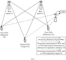
- the base station 1 is a reference base station
- the base station 2 is a non-reference base station
- UE_ref represents the reference UE
- T1 represents the clock offset between base station 2 and base station 1
- RSTD base station 2
- base station l->UE_ref represents the RSTD between base station 2 and base station 1 reported by the reference UE
- d base station 2->UE_ref
- d base station 1->UE _ref
- c represents the speed of light in unit of meter per second.
- the clock offset T1 between the base station 2 and the base station 1 can be obtained by combining the calculation formulas (1) and (2).
- the LMF entity processes each clock offset (for example, arithmetic mean, or weighted average based on the reliability indication of positioning measurement, etc.) to obtain the processed clock offset, if the same reference base station is selected when reporting the RSTD (the reference base station is autonomously selected by the reference UE, or the reference base station is configured by the LMF).
- each clock offset for example, arithmetic mean, or weighted average based on the reliability indication of positioning measurement, etc.
- the LMF entity will obtain a clock offset value between any two base stations through a certain algorithm.
- the basic principle is that the clock offset of any two base stations has a linear relationship.
- the clock offset value T1 between base station 2 and base station 1 can be obtained by using the same method as that in CASE1.
- the reference terminal since the reference terminal does not report the downlink RSTD measurement but reports the downlink TOA, if more than two reference UEs report at the same time, the same reference base station is selected for the reference UEs when calculating the RSTD.
- the clock offset value T1 between base station 2 and base station 1 can be obtained by using the same method as that in CASE1.
- Step 4 The LMF entity uses one of two following methods for processing based on the clock offset T1 calculated by the LMF entity in Step 3.
- Method 1 For terminal-assisted (UE-assisted) positioning, the LMF entity notifies each base station of the clock offset T1, each base station can correct the clock offset between each other, and then the base station sends a downlink PRS to the target UE or receives an uplink PRS from the target UE.
- Method 2 For UE-assisted positioning, the LMF entity does not notify each base station of the clock offset T1, each base station does not correct the clock offset between each other, and the LMF entity subtracts the clock offset from the RSTD value reported for the target UE or the uplink RTOA value reported by the base station of the target UE during location calculation.
- the difference between the RSTD value reported by the target UE and the clock offset is used as the modified downlink positioning measurement information, or the difference between the uplink RTOA value reported by the base station with respect to the target terminal and the clock offset is used as the modified downlink positioning measurement information.
- Step 5 The LMF entity receives the downlink positioning measurement information (including but not limited to: downlink RSTD measurement, downlink TOA measurement) reported by the target UE or the uplink positioning measurement information (RTOA value) reported by the base station, and processes respectively for the two methods in Step 4.
- the downlink positioning measurement information including but not limited to: downlink RSTD measurement, downlink TOA measurement
- RTOA value uplink positioning measurement information
- the downlink RSTD measurement reported by the target UE or the difference between the downlink TOA measurements from two base stations reported by the target UE is directly assigned to the modified RSTD measurement; or, the uplink positioning measurement information (RTOA value) reported by the base station is directly assigned to the modified RTOA measurement.
- RTOA value uplink positioning measurement information
- the LMF entity performs the operation of eliminating the clock offset in combination with the clock offset T1 between base stations obtained in Step 4, to obtain a modified downlink RSTD measurement or uplink RTOA measurement.
- the downlink is taken as an example to illustrate below. It is assumed that the base station 1 is a reference base station, the base station 2 is a non-reference base station, UE_target represents the target UE, T1 represents the clock offset between base station 2 and base station 1 calculated in Step 3, and RSTD (base station 2, base station 1->UE_target) represents the downlink RSTD measurement between base station 2 and base station 1 reported by the reference UE.
- the operation of eliminating the clock offset is as shown in formula (7).
- RSTD _ modify base station 2 , base station 1 ⁇ > UE _ target RSTD base station 2 , base station 1 ⁇ > UE _ target ⁇ T 1
- Step 6 The LMF entity performs the location calculation operation of the target UE (based on the existing Chan algorithm, etc.) based on the modified downlink RSTD measurement or uplink RTOA measurement obtained in Step 5, to obtain the location information of the target UE.
- the processing flow of the target UE includes the following steps.
- Step 1 The target UE receives the downlink PRS configuration information or the uplink PRS configuration information provided by the LMF entity or base station, where the downlink PRS configuration information includes the time-frequency position of the downlink PRS, the index information of the reference base station, etc.; the uplink PRS configuration information includes the time-frequency position of the uplink PRS, the index information of the reference base station, etc; and the configuration information is communicated via LPP signaling or RRC signaling.
- Step 2 The target UE processes for two cases of DL-TDOA and UL-TDOA positioning methods: for the DL-TDOA positioning method, proceed to Step 3; and for the UL-TDOA positioning method, proceed to Step 4.
- Step 3 Process for the DL-TDOA positioning method.
- Step 3.1 The target UE receives and measures the downlink Positioning Reference Signals (PRSs) from different base stations, and obtains a downlink positioning measurement (including but not limited to: downlink RSTD, downlink TOA) and/or a reliability indication of the downlink positioning measurement.
- PRSs downlink Positioning Reference Signals
- Step 3.2 The target UE reports the downlink positioning measurement and/or the reliability indication of the downlink positioning measurement obtained in Step 3.1 to the LMF.
- Step 4 Process for the UL-TDOA positioning method.
- Step 4.1 The target UE sends an uplink PRS to the base station.
- the processing flow on the base station (applicable to all base stations) side includes the following.
- Step 1 The base station receives the downlink PRS configuration information or uplink PRS configuration information sent by the LMF entity, and then forwards the configuration information to the UE.
- Step 2 Process for two cases of DL-TDOA and UL-TDOA positioning methods: for the DL-TDOA positioning method, proceed to Step 3; and for the UL-TDOA positioning method, proceed to Step 4.
- Step 3 Process for the DL-TDOA positioning method.
- Step 3.1 The base station sends a downlink PRS to the reference UE.
- Step 32 The base station receives the downlink positioning measurement information and the location information of the reference UE reported by the reference UE, and forwards them to the LMF entity, where the downlink positioning measurement information includes but is not limited to: downlink RSTD measurement, downlink TOA measurement.
- Step 4 Process for the UL-TDOA positioning method.
- Step 4.1 The base station receives and measures an uplink PRS sent by the reference UE to obtain the uplink positioning measurement information (i.e., an uplink RTOA value).
- the uplink positioning measurement information i.e., an uplink RTOA value
- Step 4.2 The base station reports the uplink positioning measurement information to the LMF entity, and forwards the location information of the reference UE reported by the reference UE.
- Step 5 based on the Method 1 in Step 4 of the LMF entity, when the base station receives the clock offset T1 notified by the LMF entity, each base station corrects its own clock offset independently and then processes for two cases of DL-TDOA and UL-TDOA positioning methods: for the DL-TDOA positioning method, proceed to Step 6; and for the UL-TDOA positioning method, proceed to Step 7.
- Step 6 Process for the DL-TDOA positioning method.
- Step 6.1 The base station sends a downlink PRS to the target UE.
- Step 6.2 The base station receives the downlink positioning measurement information reported by the target UE, and forwards it to the LMF entity, where the downlink positioning measurement information includes but is not limited to: downlink RSTD measurement, downlink TOA measurement.
- Step 7 Process for the UL-TDOA positioning method.
- Step 7.1 The base station receives and measures an uplink PRS sent by the target UE to obtain the uplink positioning measurement information (i.e., an uplink RTOA value).
- the uplink positioning measurement information i.e., an uplink RTOA value
- Step 7.2 The base station reports the uplink positioning measurement information to the LMF.
- how the reference UE, the target UE and the base station side determine whether to process for the DL-TDOA positioning method or for the UL-TDOA positioning method may be notified by the LMF entity to the reference UE, the target UE and the base station through the positioning signaling, which may be a signaling including the positioning reference signal configuration information or may be a separate signaling. If the positioning signaling is a separate piece of signaling, the positioning signaling may be sent before the positioning reference signal configuration information is sent, to notify the reference UE, the target UE and the base station of a need to process for the DL-TDOA positioning method or a need to process for the UL-TDOA positioning method.
- the positioning signaling may be sent before the positioning reference signal configuration information is sent, to notify the reference UE, the target UE and the base station of a need to process for the DL-TDOA positioning method or a need to process for the UL-TDOA positioning method.
- Embodiment 1 single reference UE, DL-TDOA positioning.
- the downlink positioning measurement information reported by the reference terminal is the RSTD value and/or TOA value between different base stations.
- the LMF entity uses the processing method 1 in step 4: the LMF entity notifies each base station of the clock offset T1, each base station can correct the clock offset, and then the base station sends a PRS.
- the base station 1 is a reference base station, and the base station 2 is a non-reference base station.
- the first UE#a is the reference UE dedicated to positioning; and the second UE#c is the target UE.
- the processing flow of the first UE#a includes the following.
- Step 1 The reference UE obtains the location information of the reference UE based on the pre-configuration, or calculates the location information of the reference UE through the RAT-independent positioning scheme (e.g., A-GNSS, etc.).
- the RAT-independent positioning scheme e.g., A-GNSS, etc.
- Step 2 The reference UE receives the downlink PRS configuration information provided by the LMF entity or base station, where the downlink PRS configuration information includes the time-frequency position of the downlink PRS, the index information of the reference base station, etc., and the configuration information is communicated via LPP signaling or RRC signaling.
- Step 3 The reference UE determines the DL-TDOA positioning method, and needs to proceed to Step 4.
- Step 4 Process for the DL-TDOA positioning method.
- Step 4.1 The reference UE receives and measures the downlink Positioning Reference Signals (PRSs) from different base stations, and obtains a downlink positioning measurement (including but not limited to: an RSTD value between different base stations, TOA values of different base stations) and/or a reliability indication of the downlink positioning measurement.
- PRSs downlink Positioning Reference Signals
- Step 4.2 The reference UE reports the downlink positioning measurement and/or the reliability indication of the downlink positioning measurement obtained in Step 4.1 and the location information of the reference UE obtained in Step 1 to the LMF entity or the base station.
- the processing flow of the LMF entity includes.
- Step 1 The LMF entity sends the downlink PRS configuration information or the uplink PRS configuration information to a UE, or the LMF entity sends the downlink PRS configuration information or the uplink PRS configuration information to a base station that then forwards it to the UE.
- Step 2 The LMF entity receives the location information of the reference UE and the downlink positioning measurement information (including but not limited to: an RSTD value between different base stations, separate TOA values of different base stations) reported by the reference UE.
- the downlink positioning measurement information including but not limited to: an RSTD value between different base stations, separate TOA values of different base stations
- Step 3 The LMF entity calculates a clock offset between base stations according to the location information of the reference UE reported by the reference UE and the downlink positioning measurement information reported by the reference UE received in Step 2.
- the base station 1 is a reference base station
- the base station 2 is a non-reference base station
- UE_ref represents the reference UE
- T1 represents the clock offset between base station 2 and base station 1
- RSTD base station 2
- base station l->UE_ref represents the RSTD value between base station 2 and base station 1 reported by the reference UE
- d base station 2->UE_ref
- d base station 1->UE _ref
- c represents the speed of light in unit of meter per second.
- the clock offset T1 between the base station 2 and the base station 1 can be obtained by combining the calculation formulas (8) and (9).
- the clock offset value T1 between base station 2 and base station 1 can be obtained by using the same method as that in CASE1.
- Step 4 The LMF entity uses the following method for processing based on the clock offset T1 calculated by the LMF entity in Step 3.
- the LMF entity notifies each base station of the clock offset T1, each base station can correct the clock offset, and then the base station sends a downlink PRS to the target UE or receives an uplink PRS from the target UE.
- Step 5 The LMF entity receives the downlink positioning measurement information (including but not limited to: downlink RSTD measurement, downlink TOA measurement) reported by the target UE, and performs the following process.
- the downlink positioning measurement information including but not limited to: downlink RSTD measurement, downlink TOA measurement
- Step 6 The LMF entity performs the location calculation operation of the target UE (based on the existing algorithm) based on the modified RSTD measurement obtained in Step 5, to obtain the location information of the target UE.
- the processing flow of the second UE#c includes the following.
- Step 1 The target UE receives the downlink PRS configuration information provided by the LMF entity or base station, where the downlink PRS configuration information includes the time-frequency position of the downlink PRS and the index information of the reference base station, etc., and the configuration information is communicated via LPP signaling or RRC signaling.
- Step 2 The target UE determines the DL-TDOA positioning method, and proceeds to Step 3.
- Step 3 Process for the DL-TDOA positioning method.
- Step 3.1 The target UE receives and measures the downlink Positioning Reference Signals (PRSs) from different base stations, and obtains a downlink positioning measurement (including but not limited to: an RSTD value between different base stations, TOA values of different base stations) and/or a reliability indication of the downlink positioning measurement.
- PRSs downlink Positioning Reference Signals
- Step 3.2 The target UE reports the downlink positioning measurement information obtained in Step 3 to the LMF entity.
- the processing flow of the base station (applicable to the reference base station #1 and the non-reference base station #2) includes the following.
- Step 1 The reference base station receives the downlink PRS configuration information or uplink PRS configuration information of the LMF entity, and then forwards the configuration information to the UE.
- Step 2 Determine the DL-TDOA positioning method, and proceed to Step 3.
- Step 3 Process for the DL-TDOA positioning method.
- Step 3.1 The base station sends a downlink PRS to the reference UE.
- Step 32 The base station receives the downlink positioning measurement information and the location information of the reference UE reported by the reference UE, and forwards them to the LMF entity, where the downlink positioning measurement information includes but is not limited to: an RSTD value between different base stations, separate TOA values of different base stations.
- Step 5 Based on Step 4 of the LMF entity, when the base station receives the clock offset T1 notified by the LMF entity, each base station corrects its own clock offset independently and then proceeds to Step 6 for the DL-TDOA positioning method.
- Step 6 Process for the DL-TDOA positioning method.
- Step 6.1 The base station sends a downlink PRS to the target UE.
- Step 6.2 The base station receives the downlink positioning measurement information reported by the target UE, and forwards it to the LMF entity, where the downlink positioning measurement information includes but is not limited to: an RSTD value between different base stations, separate TOA values of different base stations.
- Embodiment 2 multiple reference UEs, DL-TDOApositioning.
- the downlink positioning measurement information reported by the reference terminal is the RSTD value between different base stations.
- the LMF entity uses the processing method 2 in step 4, that is, the LMF entity does not notify each base station of the clock offset T1, each base station does not correct the clock offset between each other, and the LMF entity subtracts the clock offset from the RSTD value reported for the target UE during location calculation.
- the first UE#a and the first UE#b are reference UEs dedicated to positioning measurement; and the second UE#c is the target UE.
- the processing flow of the first UE includes the following.
- Step 1 The reference UE calculates the location information of the reference UE based on the pre-configured location information or through the RAT-independent positioning scheme (e.g., A-GNSS, etc.).
- the RAT-independent positioning scheme e.g., A-GNSS, etc.
- Step 2 Receive the downlink PRS configuration information provided by the LMF entity or base station, where the downlink PRS configuration information includes the time-frequency position of the downlink PRS, the index information of the reference base station, etc., and the configuration information is communicated via LPP signaling or RRC signaling.
- Step 3 The reference UE determines the DL-TDOA positioning method, and proceeds to Step 4.
- Step 4 Process for the DL-TDOA positioning method.
- Step 4.1 The reference UE receives and measures the downlink Positioning Reference Signals (PRSs) from different base stations, and obtains a downlink positioning measurement (including but not limited to: downlink RSTD, downlink TOA) and/or a reliability indication of the downlink positioning measurement.
- PRSs downlink Positioning Reference Signals
- Step 4.2 The reference UE reports the downlink positioning measurement information obtained in Step 4.1 and the location information of the reference UE obtained in Step 1 to the LMF entity or the base station.
- the processing flow of the LMF entity includes the following.
- Step 1 The LMF entity sends the downlink PRS configuration information to a UE, or the LMF entity sends the downlink PRS configuration information to a base station that then forwards it to the UE.
- Step 2 The LMF entity receives the location information of the reference UE reported by the reference UE, and the downlink positioning measurement information (including but not limited to: downlink RSTD measurement, downlink TOA measurement) reported by the reference UE.
- the downlink positioning measurement information including but not limited to: downlink RSTD measurement, downlink TOA measurement
- Step 3 The LMF entity calculates a clock offset between base stations according to the location information of the reference UE reported by the reference UE and the downlink positioning measurement information reported by the reference UE received in Step 2.
- UE_ref represents the reference UEs a and b
- T1 represents the clock offset between base station 2 and base station 1
- RSTD base station 2
- base station l->UE_ref represents the RSTD between base station 2 and base station 1 reported by the reference UE
- d base station 2->UE_ref
- d base station l->UE_ref
- c represents the speed of light in unit of meter per second.
- the clock offset T1(a) between the base station 2 and base station 1 estimated based on the reference UE a can be obtained by combining Formula (13) and Formula (14); and the clock offset T1(b) between the base station 2 and base station 1 estimated based on the reference UE b can be obtained by combining Formula (15) and Formula (16).
- CASE 2 When the reference base stations selected by multiple reference UEs are not the same base station, the LMF entity will obtain a clock offset value between any two base stations through an algorithm.
- the basic principle is that the clock offset of any two base stations has a linear relationship.
- the two reference UEs a and b respectively assume that the base station 1 and base station 2 are reference base stations, and the base station 3 is also included in addition to the base station 1 and base station 2.
- the downlink RSTD measurements of the base station 2 and base station 3 relative to the reference base station 1 can be obtained. It is assumed that T1(base station 2, base station 1) represents the clock offset of the base station 2 relative to the reference base station 1, and T1(base station 3, base station 1) represents the clock offset of the base station 3 relative to the reference base station 1.
- T1(base station 2, base station 1) and T1(base station 3, base station 1) can be obtained by combining the formulas (17) and (20).
- the downlink RSTD measurements of the base station 1 and base station 3 relative to the reference base station 2 can be obtained. It is assumed that T2(base station 1, base station 2) represents the clock offset of the base station 1 relative to the reference base station 2, and T2(base station 3, base station 2) represents the clock offset of the base station 3 relative to the reference base station 2.
- T2(base station 1, base station 2) and T2(base station 3, base station 2) can be obtained by combining the formulas (21) and (24).
- the base station 1 is used as a benchmark to adjust the clock offsets of the base station 2 and base station 3 relative to the base station 1, example is shown as follows.
- the clock offset of the base station 2 relative to the base station 1 is: (T1(base station 2, base station 1) - T2(base station 1, base station 2))/2.
- the clock offset of the base station 3 relative to the base station 1 is: (T1(base station 3, base station 1) + (T2(base station 3, base station 2) - T2(base station 1, base station 2))/2)/2.
- the weight processing can also be performed combined with the quality indication of the positioning measurement information.
- the weight processing can also be performed combined with the quality indication of the positioning measurement information.
- w1 is a weighting coefficient, of which the value is between 0 and 1.
- Step 4 The LMF entity uses the Method 2 for processing based on the clock offset T1 calculated by the LMF entity in Step 3.
- Method 2 For UE-assisted positioning, the LMF entity does not notify each base station of the clock offset T1, each base station does not correcr the clock offset between each other, and the LMF entity subtracts the clock offset from the RSTD value reported for the target UE during location calculation.
- Step 5 The LMF entity receives the downlink positioning measurement information (including but not limited to: downlink RSTD measurement, downlink TOA measurement) reported by the target UE, and the LMF entity performs the operation of eliminating the clock offset in combination with the clock offset T1 between base stations obtained in Step 4, to obtains a modified RSTD measurement.
- the downlink positioning measurement information including but not limited to: downlink RSTD measurement, downlink TOA measurement
- the base station 1 is a reference base station
- the base station 2 is a non-reference base station
- UE target represents the target UE
- T1 represents the clock offset between base station 2 and base station 1 calculated in Step 3
- RSTD base station 2, base station 1->UE_target
- the operation of eliminating the clock offset is as shown in formula (25).
- Step 6 The LMF performs the location calculation operation of the target UE (based on the existing Chan algorithm, etc.) based on the modified RSTD measurement obtained in Step 5, to obtain the location information of the target UE.
- the processing flow of the second UE includes the following.
- Step 1 The target UE receives the downlink PRS configuration information provided by the LMF entity or base station, where the downlink PRS configuration information includes the time-frequency position of the downlink PRS, the index information of the reference base station, etc., and the configuration information is communicated via LPP signaling or RRC signaling.
- Step 2 The target UE determines the DL-TDOA positioning method, and proceeds to Step 3.
- Step 3 Process for the DL-TDOA positioning method.
- Step 3.1 The target UE receives and measures the downlink Positioning Reference Signals (PRSs) from different base stations, and obtains a downlink positioning measurement (including but not limited to: downlink RSTD, downlink TOA) and/or a reliability indication of the downlink positioning measurement.
- PRSs downlink Positioning Reference Signals
- Step 3.2 The target UE reports the downlink positioning measurement and/or the reliability indication of the downlink positioning measurement obtained in Step 3.1 to the LMF entity.
- the processing flow of the base station includes the following.
- Step 1 The reference base station receives the downlink PRS configuration information of the LMF entity, and then forwards the configuration information to the UE.
- Step 2 Determine the DL-TDOA positioning method, and proceed to Step 3.
- Step 3 Process for the DL-TDOA positioning method.
- Step 3.1 The base station sends a downlink PRS to the reference UE.
- Step 32 The base station receives the downlink positioning measurement information and the location information of the reference UE reported by the reference UE, and forwards them to the LMF entity, where the downlink positioning measurement information includes but is not limited to: downlink RSTD measurement, downlink TOA measurement.
- Step 5 Based on Step 4 of the LMF entity, when the base station receives the clock offset T1 notified by the LMF entity, each base station corrects its own clock offset independently and then proceeds to Step 6 for the DL-TDOA positioning method.
- Step 6 Process for the DL-TDOA positioning method.
- Step 6.1 The base station sends a downlink PRS to the target UE.
- Step 6.2 The base station receives the downlink positioning measurement information reported by the target UE, and forwards it to the LMF entity, wherein the downlink positioning measurement information includes but is not limited to: downlink RSTD measurement, downlink TOA measurement.
- Embodiment 3 single reference UE, UL-TDOA positioning.
- the base station receives an uplink PRS sent by the reference UE, and obtains the uplink positioning measurement information (uplink RTOA value) and reports it to the LMF entity.
- the LMF entity uses the processing method 1 in step 4: the LMF entity notifies each base station of the clock offset T1, each base station can correct the clock offset, and then the base station receives the uplink PRS.
- the base station 1 is a reference base station, and the base station 2 is a non-reference base station.
- the first UE a is the reference UE dedicated to positioning; and the second UE c is the target UE.
- the processing flow of the first UE includes the following.
- Step 1 The reference UE calculates the location information of the reference UE based on the pre-configured location information or through the RAT-independent positioning scheme (e.g., A-GNSS, etc.).
- the RAT-independent positioning scheme e.g., A-GNSS, etc.
- Step 2 Receive the uplink PRS configuration information provided by the LMF entity or base station, where the uplink PRS configuration information includes the time-frequency position of the uplink PRS, the index information of the reference base station, etc., and the configuration information is communicated via LPP signaling or RRC signaling.
- Step 3 The reference UE determines to process for the UL-TDOA positioning method, and proceeds to Step 5.
- Step 5 Process for the UL-TDOA positioning method.
- Step 5.1 The reference UE sends an uplink PRS to the base station.
- Step 5.2 The reference UE reports the location information of the reference UE obtained in Step 1 to the LMF entity or the base station.
- the processing flow of the LMF entity includes the following.
- Step 1 The LMF entity sends the uplink PRS configuration information to a UE, or the LMF entity sends the uplink PRS configuration information to a base station that then forwards it to the UE.
- Step 2 The LMF entity receives the location information of the reference UE reported by the reference UE, and the uplink positioning measurement information (i.e., uplink RTOA value) reported by the base station.
- the uplink positioning measurement information i.e., uplink RTOA value
- Step 3 The LMF entity calculates a clock offset between base stations according to the location information of the reference UE reported by the reference UE and the uplink positioning measurement information reported by the base station received in Step 2.
- the base station 1 is a reference base station
- the base station 2 is a non-reference base station
- UE_ref represents the reference UE
- T1 represents the clock offset between base station 2 and base station 1
- RSTD base station 2
- base station l->UE_ref represents the RSTD between base station 2 and base station 1 reported by the reference UE
- d base station 2->UE_ref
- d base station l->UE_ref
- c represents the speed of light in unit of meter per second.
- how the LMF entity calculates the clock offset between base stations will be introduced according to the event that the positioning measurement information reported by the reference terminal or the base station is uplink RTOAs obtained by measurements of different base stations based on the uplink PRS.
- the clock offset T1 between the base station 2 and the base station 1 can be obtained by combining the solution formulas (26) and (29).
- the same reference base station is selected for the reference UEs when calculating the clock offset.
- Step 4 The LMF entity uses the following Method 1 for processing based on the clock offset T1 calculated by the LMF entity in Step 3.
- the LMF entity For UE-assisted positioning, the LMF entity notifies each base station of the clock offset T1, each base station can correct the clock offset, and then the base station sends a downlink PRS to the target UE or receives an uplink PRS from the target UE.
- Step 5 The LMF entity receives the uplink positioning measurement information (RTOA value) reported by the base station, and performs the following process for the method in Step 4.
- RTOA value uplink positioning measurement information
- the LMF entity assigns the uplink positioning measurement information (RTOA value) reported by the base station directly to the modified RTOA measurement.
- RTOA value uplink positioning measurement information
- Step 6 The LMF entity performs the location calculation operation of the target UE (based on the existing Chan algorithm, etc.) based on the modified uplink RTOA measurement obtained in Step 5, to obtain the location information of the target UE.
- the processing flow of the second UE includes the following.
- Step 1 The target UE receives the uplink PRS configuration information provided by the LMF entity or base station, where the uplink PRS configuration information includes the time-frequency position of the uplink PRS, the index information of the reference base station, etc., and the configuration information is communicated via LPP signaling or RRC signaling.
- Step 2 The target UE determines to process for the UL-TDOA positioning method, and proceeds to Step 4.
- Step 4 Process for the UL-TDOA positioning method.
- Step 4.1 The target UE sends an uplink PRS to the base station.
- the processing flow of the base station includes the following.
- Step 1 The reference base station receives the uplink PRS configuration information of the LMF entity, and then forwards the configuration information to the UE.
- Step 2 Determine to process for the UL-TDOA positioning method, and proceed to Step 4.
- Step 4 Process for the UL-TDOA positioning method.
- Step 4.1 The base station receives and measures an uplink PRS sent by the reference UE to obtain the uplink positioning measurement information (i.e., an uplink RTOA value).
- the uplink positioning measurement information i.e., an uplink RTOA value
- Step 4.2 The base station reports the uplink positioning measurement information to the LMF entity, and forwards the location information of the reference UE reported by the reference UE.
- Step 5 Based on the Method 1 in Step 4 of the LMF entity, when the base station receives the clock offset T1 notified by the LMF entity, each base station corrects its own clock offset independently and then proceeds to Step 7 for the UL-TDOA positioning method.
- Step 7 Process for the UL-TDOA positioning method.
- Step 7.1 The base station receives and measures an uplink PRS sent by the target UE to obtain the uplink positioning measurement information (i.e., an uplink RTOA value).
- the uplink positioning measurement information i.e., an uplink RTOA value
- Step 7.2 The base station reports the uplink positioning measurement information to the LMF entity.
- the embodiments of the present application propose a solution for eliminating the clock offset between base stations based on the reference UE. Since the influence of the clock offset is eliminated from the RSTD measurement information of the target UE processed by the LMF entity, the UE positioning accuracy of the DL-TDOA positioning method can be improved.
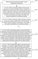
- a positioning method provided by an embodiment of the present application includes the following steps.
- the reference UE receives the downlink PRS configuration information or uplink PRS configuration information provided by the LMF entity or base station.
- S402 for a DL-TDOA positioning method: receiving and measuring downlink positioning reference signals (for example, downlink PRSs) from different base stations based on the positioning reference signal configuration information, determining downlink positioning measurement information, and reporting the downlink positioning measurement information and location information of a reference terminal, so that a LMF entity positions a target terminal based on the downlink positioning measurement information and the location information of the reference terminal.
- downlink positioning reference signals for example, downlink PRSs
- the reference UE may also report the downlink positioning measurement information and the location information of the reference terminal to the base station, the base station forwards them to the LMF entity, and finally the LMF entity positions the target terminal based on the downlink positioning measurement information and the location information of the reference terminal.
- S403 for an UL-TDOA positioning method: sending an uplink positioning reference signal (for example, uplink PRS) based on the positioning reference signal configuration information, and sending the location information of the reference terminal, so that the LMF entity positions the target terminal based on the uplink positioning reference signal and the location information of the reference terminal.
- an uplink positioning reference signal for example, uplink PRS
- the reference UE may also send an uplink positioning reference signal to the base station, and send the location information of the reference terminal to the LMF entity or the base station. If it is sent to the base station, the base station can forward the location information of the reference terminal to the LMF entity; the base station receives the uplink positioning reference signal, and determines the corresponding uplink positioning measurement information and then sends it to the LMF entity.
- the LMF entity receives the uplink positioning measurement information and the location information of the reference terminal, and determines a clock offset between base stations based on the uplink positioning measurement information and the location information of the reference terminal; modifies the uplink positioning measurement information of the target terminal according to the clock offset, and determines the modified uplink positioning measurement information of the target terminal; and determines the location information of the target terminal according to the modified uplink positioning measurement information of the target terminal.
- the positioning reference signal configuration information includes uplink and/or downlink positioning reference signal configuration information.
- the downlink positioning reference signals from different base stations are received and measured based on the downlink positioning reference signal configuration information; and for the UL-TDOA technical solution, the uplink positioning reference signal is sent based on the uplink positioning reference signal configuration information.
- the positioning reference signal described in the embodiments of the present application may be PRS, CSI-RS, SS/PBCH Block, SRS, PRACH, etc., and is not limited to PRS.
- the downlink positioning reference signals from different base stations are received and measured based on the positioning reference signal configuration information, the downlink positioning measurement information is determined, and the downlink positioning measurement information and the location information of the reference terminal are reported; and for the UL-TDOA positioning method, the uplink positioning reference signal is sent based on the positioning reference signal configuration information, and the location information of the reference terminal is sent, so that the LMF entity can calculate a clock offset between base stations based on the location information of the reference UE and the uplink/downlink positioning measurement information reported by the reference UE, and thus eliminate the clock offset between base stations, improving the UE positioning accuracy of the UL-TDOA/DL-TDOA positioning method.
- the reference terminal described in the embodiments of the present application that is, the reference terminal used to locate the target terminal, may be any terminal.
- the target terminal described in the embodiments of the present application may also be any terminal.
- the downlink positioning measurement information includes: a downlink positioning measurement and/or a reliability indication of the downlink positioning measurement, where the reliability indication is a standard deviation and/or a variance of an error estimate value of the downlink positioning measurement to indicate reliability of the downlink positioning measurement.
- the reliability indication is a standard deviation and/or a variance of an error estimate value of the downlink positioning measurement to indicate reliability of the downlink positioning measurement.
- the location information of the reference terminal is determined by the reference terminal based on pre-configured location information or through an RAT-independent positioning scheme.
- the positioning reference signal configuration information is provided by the LMF entity or a base station.
- a positioning method provided by an embodiment of the present application includes the following.
- S501 for a DL-TDOA positioning method: receiving downlink positioning measurement information and location information of a reference terminal reported by the reference terminal, and receiving downlink positioning measurement information reported by a target terminal; and positioning the target terminal based on the downlink positioning measurement information and the location information of the reference terminal reported by the reference terminal as well as the downlink positioning measurement information reported by the target terminal; and/or
- S502 for an UL-TDOA positioning method: receiving location information of a reference terminal reported by the reference terminal, and receiving uplink positioning measurement information of the reference terminal reported by a base station and uplink positioning measurement information of the target terminal reported by the base station; and positioning the target terminal based on the uplink positioning measurement information of the reference terminal, the location information of the reference terminal, and the uplink positioning measurement information of the target terminal.
- the positioning the target terminal based on the downlink positioning measurement information and the location information of the reference terminal reported by the reference terminal as well as the downlink positioning measurement information reported by the target terminal includes:
- the positioning the target terminal based on the uplink positioning measurement information of the reference terminal and the location information of the reference terminal reported by the base station as well as the uplink positioning measurement information of the target terminal reported by the base station includes:
- the modified downlink positioning measurement information includes: a downlink RSTD measurement.
- the method before obtaining the location information and the downlink positioning measurement information of the reference terminal, the method further includes: sending downlink positioning reference signal configuration information to a terminal; or sending the downlink positioning reference signal configuration information to the base station, so that the base station forwards the downlink positioning reference signal configuration information to the terminal.
- the location information of the reference terminal is reported by the reference terminal;
- the downlink positioning measurement information is the downlink positioning measurement information reported by the reference terminal.
- modifying the downlink positioning measurement information of the target terminal according to the clock offset to determine the modified downlink positioning measurement information of the target terminal specifically includes:
- the modified uplink positioning measurement information includes an uplink RTOA measurement.
- the method before obtaining the location information and the uplink positioning measurement information of the reference terminal, the method further includes: sending uplink positioning reference signal configuration information to a terminal; or sending the uplink positioning reference signal configuration information to the base station, so that the base station forwards the uplink positioning reference signal configuration information to the terminal.
- the modifying the uplink positioning measurement information of the target terminal according to the clock offset to determine the modified uplink positioning measurement information of the target terminal specifically includes:
- a positioning method provided by an embodiment of the present application includes the following.
- the positioning reference signal configuration information includes uplink and/or downlink positioning reference signal configuration information.
- the target UE receives the downlink PRS configuration information or uplink PRS configuration information provided by the LMF entity or base station.
- S602 for a DL-TDOA positioning method: receiving and measuring downlink positioning reference signals from different base stations based on the positioning reference signal configuration information, determining downlink positioning measurement information, and reporting the downlink positioning measurement information; and/or
- S603 for an UL-TDOA positioning method: sending an uplink positioning reference signal based on the positioning reference signal configuration information.
- the downlink positioning measurement information includes: a downlink positioning measurement and/or a reliability indication of the downlink positioning measurement, where the reliability indication is a standard deviation and/or a variance of an error estimate value of the downlink positioning measurement to indicate reliability of the downlink positioning measurement.
- the reliability indication is a standard deviation and/or a variance of an error estimate value of the downlink positioning measurement to indicate reliability of the downlink positioning measurement.
- the positioning reference signal configuration information is provided by the LMF entity or a base station.
- a positioning method provided by an embodiment of the present application includes the following.
- S701 sending positioning reference signal configuration information to a terminal.
- the positioning reference signal configuration information includes uplink and/or downlink positioning reference signal configuration information.
- the base station receives the downlink PRS configuration information or uplink PRS configuration information sent by the LMF entity, and then forwards the configuration information to the UE.
- S702 for a DL-TDOA positioning method: sending a downlink positioning reference signal to a reference terminal, receiving downlink positioning measurement information and location information of the reference terminal reported by the reference terminal, and forwarding the downlink positioning measurement information and the location information of the reference terminal to an LMF entity.
- S703 for an UL-TDOA positioning method: receiving and measuring an uplink positioning reference signal sent by the reference terminal to obtain uplink positioning measurement information, reporting the uplink positioning measurement information to the LMF entity, and forwarding location information of the reference terminal reported by the reference terminal.
- the method further includes:
- a positioning apparatus (which may be any type of terminal) provided by an embodiment of the present application includes:
- the downlink positioning measurement information includes: a downlink positioning measurement and/or a reliability indication of the downlink positioning measurement, where the reliability indication is a standard deviation and/or a variance of an error estimate value of the downlink positioning measurement to indicate reliability of the downlink positioning measurement.
- the reliability indication is a standard deviation and/or a variance of an error estimate value of the downlink positioning measurement to indicate reliability of the downlink positioning measurement.
- the location information of the reference terminal is determined by the reference terminal based on pre-configured location information or through an RAT-independent positioning scheme.
- the positioning reference signal configuration information is provided by the LMF entity or a base station.
- a transceiver 810 is configured to receive and send data under the control of the processor 800.
- the bus architecture may include any numbers of interconnected buses and bridges, and specifically link various circuits of one or more processors represented by the processor 800 and the memory represented by the memory 820.
- the bus architecture may further link various other circuits such as peripheral device, voltage regulator and power management circuit, which are all well known in the art and thus will not be further described again herein.
- the bus interface provides an interface.
- the transceiver 810 may be a plurality of elements, i.e., include a transmitter and a receiver, and provide the units for communicating with various other devices over the transmission media.
- the user interface 830 can also be the interface capable of inter-connecting or exter-connecting with the required devices, and the connected devices include but not limited to keypad, display, loudspeaker, microphone, joystick and the like.
- the processor 800 is responsible for managing the bus architecture and general processing, and the memory 820 may store the data used by the processor 800 when performing the operations.
- the processor 800 may be Central Processing Unit (CPU), Application Specific Integrated Circuit (ASIC), Field-Programmable Gate Array (FPGA) or Complex Programmable Logic Device (CPLD).
- CPU Central Processing Unit
- ASIC Application Specific Integrated Circuit
- FPGA Field-Programmable Gate Array
- CPLD Complex Programmable Logic Device
- a positioning apparatus (which may be an LMF entity) provided by an embodiment of the present application includes:
- the processor 900 is specifically configured to:
- the modified downlink positioning measurement information includes: a downlink RSTD measurement.
- the processor 900 is further configured to invoke the program instructions stored in the memory and execute according to an obtained program: sending downlink positioning reference signal configuration information to a terminal; or sending the downlink positioning reference signal configuration information to the base station, so that the base station forwards the downlink positioning reference signal configuration information to the terminal.
- the processor 900 is specifically configured to:
- the modified uplink positioning measurement information includes an uplink RTOA measurement.
- the processor 900 is further configured to invoke the program instructions stored in the memory 920 and execute according to an obtained program: sending uplink positioning reference signal configuration information to a terminal; or sending the uplink positioning reference signal configuration information to the base station so that the base station forwards the uplink positioning reference signal configuration information to the terminal.
- the processor 900 when modifying the uplink positioning measurement information of the target terminal according to the clock offset to determine the modified uplink positioning measurement information of the target terminal, the processor 900 is specifically configured to invoke the program instructions stored in the memory 920 and execute according to an obtained program:
- the transceiver 910 is configured to receive and send data under the control of the processor 900.
- the bus architecture may include any numbers of interconnected buses and bridges, and specifically link various circuits of one or more processors represented by the processor 900 and the memory represented by the memory 920.
- the bus architecture may further link various other circuits such as peripheral device, voltage regulator and power management circuit, which are all well known in the art and thus will not be further described again herein.
- the bus interface provides an interface.
- the transceiver 910 may be a plurality of elements, i.e., include a transmitter and a receiver, and provide the units for communicating with various other devices over the transmission media.
- the processor 900 is responsible for managing the bus architecture and general processing, and the memory 920 may store the data used by the processor 900 when performing the operations.
- the processor 900 may be CPU, ASIC, FPGA or CPLD.
- a positioning apparatus (which may be any type of terminal) provided by an embodiment of the present application, of which the structure may also refer to FIG. 8 , includes:
- the downlink positioning measurement information includes: a downlink positioning measurement and/or a reliability indication of the downlink positioning measurement, where the reliability indication is a standard deviation and/or a variance of an error estimate value of the downlink positioning measurement to indicate reliability of the downlink positioning measurement.
- the reliability indication is a standard deviation and/or a variance of an error estimate value of the downlink positioning measurement to indicate reliability of the downlink positioning measurement.
- the positioning reference signal configuration information is provided by the LMF entity or a base station.
- the processor is further configured to invoke the program instructions stored in the memory and execute according to an obtained program: determining and reporting location information of a reference terminal.
- the terminal described in this embodiment of the present application may be used as a reference terminal or a target terminal, and may have the functions of the reference terminal and the target terminal at the same time.
- another positioning apparatus (which may be a base station) provided by an embodiment of the present application, of which the structure may also refer to FIG. 9 , includes:
- the processor is further configured to invoke the program instructions stored in the memory and execute according to an obtained program:
- another positioning apparatus provided by an embodiment of the present application includes:
- the downlink positioning measurement information includes: a downlink positioning measurement and/or a reliability indication of the downlink positioning measurement, where the reliability indication is a standard deviation and/or a variance of an error estimate value of the downlink positioning measurement to indicate reliability of the downlink positioning measurement.
- the reliability indication is a standard deviation and/or a variance of an error estimate value of the downlink positioning measurement to indicate reliability of the downlink positioning measurement.
- the location information of the reference terminal is determined by the reference terminal based on pre-configured location information or through an RAT-independent positioning scheme.
- the positioning reference signal configuration information is provided by the LMF entity or a base station.
- another positioning apparatus provided by an embodiment of the present application includes:
- the first downlink processing unit 21 is specifically configured to:
- the first uplink processing unit 22 is specifically configured to:
- the modified downlink positioning measurement includes: a downlink RSTD measurement.
- the apparatus further includes a first sending unit, wherein before obtaining the location information and the downlink positioning measurement information of the reference terminal, the first sending unit is configured to: send downlink positioning reference signal configuration information to a terminal; or send the downlink positioning reference signal configuration information to the base station, so that the base station forwards the downlink positioning reference signal configuration information to the terminal.
- the first sending unit before obtaining the location information and the downlink positioning measurement information of the reference terminal, the first sending unit is configured to: send downlink positioning reference signal configuration information to a terminal; or send the downlink positioning reference signal configuration information to the base station, so that the base station forwards the downlink positioning reference signal configuration information to the terminal.
- the first downlink processing unit 21 is specifically configured to:
- the modified uplink positioning measurement information includes an uplink RTOA measurement.
- the apparatus further includes a second sending unit, wherein before obtaining the location information and the uplink positioning measurement information of the reference terminal, the second sending unit is configured to: send uplink positioning reference signal configuration information to a terminal; or send the uplink positioning reference signal configuration information to the base station, so that the base station forwards the uplink positioning reference signal configuration information to the terminal.
- the second sending unit before obtaining the location information and the uplink positioning measurement information of the reference terminal, the second sending unit is configured to: send uplink positioning reference signal configuration information to a terminal; or send the uplink positioning reference signal configuration information to the base station, so that the base station forwards the uplink positioning reference signal configuration information to the terminal.
- the first uplink processing unit 22 is specifically configured to:
- another positioning apparatus provided by an embodiment of the present application includes:
- the downlink positioning measurement information includes: a downlink positioning measurement and/or a reliability indication of the downlink positioning measurement, where the reliability indication is a standard deviation and/or a variance of an error estimate value of the downlink positioning measurement to indicate reliability of the downlink positioning measurement.
- the reliability indication is a standard deviation and/or a variance of an error estimate value of the downlink positioning measurement to indicate reliability of the downlink positioning measurement.
- the positioning reference signal configuration information is provided by the LMF entity or a base station.
- another positioning apparatus provided by an embodiment of the present application includes:
- the apparatus further includes: a clock offset correction unit configured to, when receiving the clock offset between base stations notified by the LMF entity, correct a clock offset of a local base station according to the clock offset between base stations;
- each embodiment of the present application may be integrated into one processing unit, or each unit may exist alone physically, or two or more units may be integrated into one unit.
- the above-mentioned integrated units can be implemented in the form of hardware, or can be implemented in the form of software functional units.
- the integrated unit When the integrated unit is implemented in the form of software functional unit and sold or used as an independent product, it may be stored in a computer readable storage medium.
- the technical solution of the present application essentially or a part that contributes to the prior art or all or a part of the technical solution may be embodied in the form of software product.
- the computer software product is stored in a storage medium, and includes several instructions used to enable a computer device (which may be a personal computer, server, or network device, etc.) or a processor to perform all or some of the steps of the methods of various embodiments of the present application.
- the above-mentioned storage medium includes: USB flash drive, mobile hard disk, Read-Only Memory (ROM), Random Access Memory (RAM), magnetic disk or compact disc or various media that can store the program codes.
- An embodiment of the present application provides a computing device, which can specifically be a desktop computer, a portable computer, a smart phone, a tablet computer, a Personal Digital Assistant (PDA) or the like.
- the computing device can include a Center Processing Unit (CPU), a memory, input/output devices and the like.
- the input device can include a keyboard, a mouse, a touch screen and the like, and the output device can include a display device such as Liquid Crystal Display (LCD), Cathode Ray Tube (CRT) or the like.
- LCD Liquid Crystal Display
- CRT Cathode Ray Tube
- the memory can include a Read-Only Memory (ROM) and a Random Access Memory (RAM), and provide the program instructions and data stored in the memory to the processor.
- ROM Read-Only Memory
- RAM Random Access Memory
- the memory may be used to store the program of any one of the methods provided by the embodiments of the present application.
- the processor invokes the program instructions stored in the memory and is configured to perform any one of the methods provided by the embodiments of the present application in accordance with the obtained program instructions.
- An embodiment of the present application provides a computer storage medium for storing the computer program instructions used by the apparatuses provided by the embodiments of the present application described above, where the computer storage medium contains the program for performing any one of the methods provided by the embodiments of the present application described above.
- the computer storage medium may be any available media or data storage device accessible to the computer, including but not limited to magnetic memory (e.g., floppy disk, hard disk, magnetic tape, Magnetic Optical disc (MO) or the like), optical memory (e.g., CD, DVD, BD, HVD or the like), semiconductor memory (e.g., ROM, EPROM, EEPROM, nonvolatile memory (NAND FLASH), Solid State Disk (SSD)) or the like.
- magnetic memory e.g., floppy disk, hard disk, magnetic tape, Magnetic Optical disc (MO) or the like
- optical memory e.g., CD, DVD, BD, HVD or the like
- semiconductor memory e.g., ROM, EPROM, EEPROM, nonvolatile memory (NAND FLASH), Solid State Disk (SSD)
- the methods provided by the embodiments of the present application may be applied to the terminal devices, and may also be applied to the network devices.
- the terminal device can also referred to as the User Equipment ("UE” for short), Mobile Station (“MS” for short), Mobile Terminal (“MT” for short) or the like.
- the terminal can has the ability of communicating with one or more core networks via the Radio Access Network (RAN).
- RAN Radio Access Network
- the terminal can be a mobile telephone (or called "cellular" telephone), or a computer with the mobile property.
- the terminal can also be a portable, pocket, handheld, computer built-in or vehicle-carried mobile device.
- the network device may be a base station (e.g., access point), which means the device in the access network communicating with the wireless terminal via one or more sectors over the air interface.
- the base station may be used to perform the inter-conversion between the received air frame and the IP packet, and used as the router between the wireless terminal and the rest of the access network, wherein the rest of the access network may include Internet Protocol (IP) networks.
- IP Internet Protocol
- the base station may further coordinate the attribute management of the air interface.
- the base station can be the BTS in the GSM or CDMA, or can be the NodeB in the WCDMA, or can be the NodeB or eNB or e-NodeB (evolutional Node B) in the LTE, or can be the gNB in the 5G system, or the like, which is not limited in the embodiments of the present application.
- the processing flows of the above methods may be implemented by a software program, which may be stored in a storage medium. When the stored software program is invoked, the above method steps are performed.
- the embodiments of the present application can provide methods, systems and computer program products.
- the present application can take the form of hardware embodiments alone, software embodiments alone, or embodiments combining the software and hardware aspects.
- the present application can take the form of computer program products implemented on one or more computer usable storage mediums (including but not limited to magnetic disk memories, optical memories and the like) containing computer usable program codes therein.
- These computer program instructions can also be stored in a computer readable memory which is capable of guiding the computer or another programmable data processing device to operate in a particular way, so that the instructions stored in the computer readable memory produce a manufacture including the instruction apparatus which implements the functions specified in one or more processes of the flow charts and/or one or more blocks of the block diagrams.
- These computer program instructions can also be loaded onto the computer or another programmable data processing device, so that a series of operation steps are performed on the computer or another programmable device to produce the computer-implemented processing.
- the instructions executed on the computer or another programmable device provide steps for implementing the functions specified in one or more processes of the flow charts and/or one or more blocks of the block diagrams.
Landscapes
- Engineering & Computer Science (AREA)
- Signal Processing (AREA)
- Computer Networks & Wireless Communication (AREA)
- Physics & Mathematics (AREA)
- General Physics & Mathematics (AREA)
- Radar, Positioning & Navigation (AREA)
- Remote Sensing (AREA)
- Position Fixing By Use Of Radio Waves (AREA)
- Mobile Radio Communication Systems (AREA)
- Vehicle Body Suspensions (AREA)
- Auxiliary Devices For And Details Of Packaging Control (AREA)
- Die Bonding (AREA)
Abstract
Description
- The application claims the priority from
Chinese Patent Application No. 202010606012.4, filed with the China National Intellectual Property Administration on June 29, 2020 - The application relates to the field of communication technologies, and particularly to a positioning method and apparatus.
- The 3rd Generation Partnership Project (3GPP) defines various User Equipment (UE) positioning methods by measuring the Positioning Reference Signal (PRS) of the 3GPP wireless communication system, such as: Downlink Time Difference Of Arrival (DL-TDOA), Uplink Time Difference Of Arrival (UL-TDOA) and so on. These methods are based on the PRS of the wireless communication system itself, and can work in the environment with no positioning reference signals outside the network received.
- The embodiments of the present application provide a positioning method and apparatus, so as to eliminate the clock offset between base stations and improve the UE positioning accuracy of the UL-TDOA/DL-TDOA positioning method.
- At the reference terminal side, a positioning method provided by an embodiment of the present application includes:
- determining positioning reference signal configuration information;
- for a DL-TDOA positioning method: receiving and measuring downlink positioning reference signals from different base stations based on the positioning reference signal configuration information, determining downlink positioning measurement information, and reporting the downlink positioning measurement information and location information of a reference terminal, so that a Location Management Function, LMF, entity positions a target terminal based on the downlink positioning measurement information and the location information of the reference terminal;
- for an Uplink Time Difference Of Arrival, UL-TDOA, positioning method: sending an uplink positioning reference signal based on the positioning reference signal configuration information, and sending the location information of the reference terminal, so that the LMF entity positions the target terminal based on the uplink positioning reference signal and the location information of the reference terminal.
- Through this method, for the DL-TDOA positioning method, the downlink positioning reference signals from different base stations are received and measured based on the positioning reference signal configuration information, the downlink positioning measurement information is determined, and the downlink positioning measurement information and the location information of the reference terminal are reported; and for the UL-TDOA positioning method, the uplink positioning reference signal is sent based on the positioning reference signal configuration information, and the location information of the reference terminal is sent, so that the LMF entity can calculate a clock offset between base stations based on the location information of the reference UE and the uplink/downlink positioning measurement information reported by the reference UE, and thus eliminate the clock offset between base stations, improving the UE positioning accuracy of the UL-TDOA/DL-TDOA positioning method.
- Optionally, the downlink positioning measurement information comprises: a downlink positioning measurement and/or a reliability indication of the downlink positioning measurement, where the reliability indication is a standard deviation and/or a variance of an error estimate value of the downlink positioning measurement to indicate reliability of the downlink positioning measurement.
- Optionally, the location information of the reference terminal is determined by the reference terminal based on pre-configured location information or through a Radio Access Technology-independent (RAT-independent) positioning scheme.
- Optionally, the positioning reference signal configuration information is provided by the LMF entity or a base station.
- At the LMF entity side, a positioning method provided by an embodiment of the present application includes:
- for a DL-TDOA positioning method: receiving downlink positioning measurement information and location information of a reference terminal reported by the reference terminal, and receiving downlink positioning measurement information reported by a target terminal; and positioning the target terminal based on the downlink positioning measurement information and the location information of the reference terminal reported by the reference terminal as well as the downlink positioning measurement information reported by the target terminal; and/or
- for an UL-TDOA positioning method: receiving location information of a reference terminal reported by the reference terminal, and receiving uplink positioning measurement information of the reference terminal reported by a base station and uplink positioning measurement information of the target terminal reported by the base station; and positioning the target terminal based on the uplink positioning measurement information of the reference terminal, the location information of the reference terminal, and the uplink positioning measurement information of the target terminal.
- Optionally, the positioning the target terminal based on the downlink positioning measurement information and the location information of the reference terminal reported by the reference terminal as well as the downlink positioning measurement information reported by the target terminal, includes:
- determining a clock offset between base stations according to the obtained location information and the downlink positioning measurement information of the reference terminal;
- modifying the downlink positioning measurement information of the target terminal according to the clock offset to determine modified downlink positioning measurement information of the target terminal;
- determining location information of the target terminal according to the modified downlink positioning measurement information of the target terminal.
- Optionally, the positioning the target terminal based on the uplink positioning measurement information of the reference terminal and the location information of the reference terminal reported by the base station as well as the uplink positioning measurement information of the target terminal reported by the base station, includes:
- determining a clock offset between base stations according to the obtained location information and the uplink positioning measurement information of the reference terminal;
- modifying the uplink positioning measurement information of the target terminal according to the clock offset to determine modified uplink positioning measurement information of the target terminal;
- determining location information of the target terminal according to the modified uplink positioning measurement information of the target terminal.
- Optionally, the modified downlink positioning measurement information includes: a downlink Reference Signal Time Difference (RSTD) measurement.
- Optionally, before obtaining the location information and the downlink positioning measurement information of the reference terminal, the method further includes:
sending downlink positioning reference signal configuration information to a terminal; or sending the downlink positioning reference signal configuration information to the base station, so that the base station forwards the downlink positioning reference signal configuration information to the terminal. - Optionally, modifying the downlink positioning measurement information of the target terminal according to the clock offset to determine the modified downlink positioning measurement information of the target terminal, specifically includes:
- notifying the base station of the clock offset so that the base station sends a downlink positioning reference signal to the target terminal after correcting the clock offset between base stations; and assigning an RSTD reported by the target terminal or a difference between downlink TOAs from base stations reported by the target terminal directly to a modified RSTD;
- or, taking a difference between an RSTD value reported by the target terminal and the clock offset as the modified downlink positioning measurement information in a location calculation process.
- Optionally, the modified uplink positioning measurement information includes an uplink Relative Time Of Arrival (RTOA) measurement.
- Optionally, before obtaining the location information and the uplink positioning measurement information of the reference terminal, the method further includes:
sending uplink positioning reference signal configuration information to a terminal; or sending the uplink positioning reference signal configuration information to the base station, so that the base station forwards the uplink positioning reference signal configuration information to the terminal. - Optionally, the modifying the uplink positioning measurement information of the target terminal according to the clock offset to determine the modified uplink positioning measurement information of the target terminal, specifically includes:
- notifying the base station of the clock offset so that the base station receives an uplink sounding reference signal from the target terminal after correcting the clock offset between base stations; and assigning an uplink RTOA reported by the base station directly to a modified RTOA;
- or, taking a difference between an uplink RTOA value reported by the base station with respect to the target terminal and the clock offset as the modified uplink positioning measurement information in a location calculation process.
- At the target terminal side, a positioning method provided by an embodiment of the present application includes:
- determining positioning reference signal configuration information;
- for a DL-TDOA positioning method: receiving and measuring downlink positioning reference signals from different base stations based on the positioning reference signal configuration information, determining downlink positioning measurement information, and reporting the downlink positioning measurement information; and/or
- for an UL-TDOA positioning method: sending an uplink positioning reference signal based on the positioning reference signal configuration information.
- Optionally, the downlink positioning measurement information comprises: a downlink positioning measurement and/or a reliability indication of the downlink positioning measurement, wherein the reliability indication is a standard deviation and/or a variance of an error estimate value of the downlink positioning measurement to indicate reliability of the downlink positioning measurement.
- Optionally, the positioning reference signal configuration information is provided by the LMF entity or a base station.
- At the base station side, a positioning method provided by an embodiment of the present application includes:
- sending positioning reference signal configuration information to a terminal;
- for a DL-TDOA positioning method: sending a downlink positioning reference signal to a reference terminal, receiving downlink positioning measurement information and location information of the reference terminal reported by the reference terminal, and forwarding the downlink positioning measurement information and the location information of the reference terminal to a LMF entity; and/or
- for an UL-TDOA positioning method: receiving and measuring an uplink positioning reference signal sent by the reference terminal to obtain uplink positioning measurement information, reporting the uplink positioning measurement information to the LMF entity, and forwarding location information of the reference terminal reported by the reference terminal.
- Optionally, the method further includes:
- when receiving a clock offset between base stations notified by the LMF entity, correcting a clock offset of a local base station according to the clock offset between base stations;
- for the DL-TDOA positioning method: sending a downlink positioning reference signal to a target terminal, receiving downlink positioning measurement information reported by the target terminal, and forwarding the downlink positioning measurement information to the LMF entity;
- for the UL-TDOA positioning method: receiving and measuring an uplink positioning reference signal sent by the target terminal to obtain uplink positioning measurement information of the target terminal, and reporting the uplink positioning measurement information of the target terminal to the LMF entity.
- At the reference terminal side, a positioning apparatus provided by an embodiment of the present application includes:
- a memory configured to store program instructions;
- a processor configured to invoke the program instructions stored in the memory and execute according to an obtained program:
- determining positioning reference signal configuration information;
- for a DL-TDOA positioning method: receiving and measuring downlink positioning reference signals from different base stations based on the positioning reference signal configuration information, determining downlink positioning measurement information, and reporting the downlink positioning measurement information and location information of a reference terminal, so that a LMF entity positions a target terminal based on the downlink positioning measurement information and the location information of the reference terminal; and/or
- for an UL-TDOA positioning method: sending an uplink positioning reference signal based on the positioning reference signal configuration information, and sending the location information of the reference terminal, so that the LMF entity positions the target terminal based on the downlink positioning measurement information and the location information of the reference terminal.
- Optionally, the downlink positioning measurement information comprises: a downlink positioning measurement and/or a reliability indication of the downlink positioning measurement, wherein the reliability indication is a standard deviation and/or a variance of an error estimate value of the downlink positioning measurement to indicate reliability of the downlink positioning measurement.
- Optionally, the location information of the reference terminal is determined by the reference terminal based on pre-configured location information or through an RAT-independent positioning scheme.
- Optionally, the positioning reference signal configuration information is provided by the LMF entity or a base station.
- At the LMF entity side, a positioning apparatus provided by an embodiment of the present application includes:
- a memory configured to store program instructions;
- a processor configured to invoke the program instructions stored in the memory and execute according to an obtained program:
- for a DL-TDOA positioning method: receiving downlink positioning measurement information and location information of a reference terminal reported by the reference terminal, and receiving downlink positioning measurement information reported by a target terminal; and positioning the target terminal based on the downlink positioning measurement information and the location information of the reference terminal reported by the reference terminal as well as the downlink positioning measurement information reported by the target terminal; and/or
- for an UL-TDOA positioning method: receiving location information of a reference terminal reported by the reference terminal, and receiving uplink positioning measurement information of the reference terminal reported by a base station and uplink positioning measurement information of the target terminal reported by the base station; and positioning the target terminal based on the uplink positioning measurement information of the reference terminal, the location information of the reference terminal, and the uplink positioning measurement information of the target terminal.
- Optionally, when positioning the target terminal based on the downlink positioning measurement information and the location information of the reference terminal reported by the reference terminal as well as the downlink positioning measurement information reported by the target terminal, the processor is configured to invoke the program instructions stored in the memory and execute according to an obtained program:
- determining a clock offset between base stations according to the obtained location information and the downlink positioning measurement information of the reference terminal;
- modifying the downlink positioning measurement information of the target terminal according to the clock offset to determine modified downlink positioning measurement information of the target terminal;
- determining location information of the target terminal according to the modified downlink positioning measurement information of the target terminal.
- Optionally, when modifying the uplink positioning measurement information of the target terminal according to the clock offset to determine the modified uplink positioning measurement information of the target terminal, the processor is specifically configured to invoke the program instructions stored in the memory and execute according to an obtained program:
- determining a clock offset between base stations according to the obtained location information and the uplink positioning measurement information of the reference terminal;
- modifying the uplink positioning measurement information of the target terminal according to the clock offset to determine modified uplink positioning measurement information of the target terminal;
- determining location information of the target terminal according to the modified uplink positioning measurement information of the target terminal.
- Optionally, the modified downlink positioning measurement information includes: a downlink RSTD measurement.
- Optionally, before obtaining the location information and the downlink positioning measurement information of the reference terminal, the processor is further configured to invoke the program instructions stored in the memory and execute according to an obtained program:
sending downlink positioning reference signal configuration information to a terminal; or sending the downlink positioning reference signal configuration information to the base station, so that the base station forwards the downlink positioning reference signal configuration information to the terminal. - Optionally, when determining the modified downlink positioning measurement information of the target terminal according to the clock offset, the processor is specifically configured to:
- notify the base station of the clock offset so that the base station sends a downlink positioning reference signal to the target terminal after correcting the clock offset between base stations; and assign an RSTD reported by the target terminal or a difference between downlink TOAs from base stations reported by the target terminal directly to a modified RSTD;
- or, take a difference between an RSTD value reported by the target terminal and the clock offset as the modified downlink positioning measurement information in a location calculation process.
- Optionally, the modified uplink positioning measurement information includes an uplink RTOA measurement.
- Optionally, before obtaining the location information and the uplink positioning measurement information of the reference terminal, the processor is further configured to invoke the program instructions stored in the memory and execute according to an obtained program:
sending uplink positioning reference signal configuration information to a terminal; or sending the uplink positioning reference signal configuration information to the base station, so that the base station forwards the uplink positioning reference signal configuration information to the terminal. - Optionally, when modifying the uplink positioning measurement information of the target terminal according to the clock offset to determine the modified uplink positioning measurement information of the target terminal, the processor is specifically configured to invoke the program instructions stored in the memory and execute according to an obtained program:
- notifying the base station of the clock offset so that the base station receives an uplink sounding reference signal from the target terminal after correcting the clock offset between base stations; and assigning an uplink RTOA reported by the base station directly to a modified RTOA;
- or, taking a difference between an uplink RTOA value reported by the base station with respect to the target terminal and the clock offset as the modified uplink positioning measurement information in a location calculation process.
- At the target terminal side, a positioning apparatus provided by an embodiment of the present application includes:
- a memory configured to store program instructions;
- a processor configured to invoke the program instructions stored in the memory and execute according to an obtained program:
- determining positioning reference signal configuration information;
- for a DL-TDOA positioning method: receiving and measuring downlink positioning reference signals from different base stations based on the positioning reference signal configuration information, determining downlink positioning measurement information, and reporting the downlink positioning measurement information; and/or
- for an UL-TDOA positioning method: sending an uplink positioning reference signal based on the positioning reference signal configuration information.
- Optionally, the downlink positioning measurement information comprises: a downlink positioning measurement and/or a reliability indication of the downlink positioning measurement, where the reliability indication is a standard deviation and/or a variance of an error estimate value of the downlink positioning measurement to indicate reliability of the downlink positioning measurement.
- Optionally, the positioning reference signal configuration information is provided by the LMF entity or a base station.
- Optionally, the processor is further configured to invoke the program instructions stored in the memory and execute according to an obtained program:
determining and reporting location information of a reference terminal. - At the base station side, a positioning apparatus provided by an embodiment of the present application includes:
- a memory configured to store program instructions;
- a processor configured to invoke the program instructions stored in the memory and execute according to an obtained program:
- sending positioning reference signal configuration information to a terminal;
- for a DL-TDOA positioning method: sending a downlink positioning reference signal to a reference terminal, receiving downlink positioning measurement information and location information of the reference terminal reported by the reference terminal, and forwarding the downlink positioning measurement information and the location information of the reference terminal to a Location Management Function, LMF, entity; and/or
- for an UL-TDOA positioning method: receiving and measuring an uplink positioning reference signal sent by the reference terminal to obtain uplink positioning measurement information, reporting the uplink positioning measurement information to the LMF entity, and forwarding the location information of the reference terminal reported by the reference terminal.
- Optionally, the processor is further configured to invoke the program instructions stored in the memory and execute according to an obtained program:
- when receiving a clock offset between base stations notified by the LMF entity, correcting a clock offset of a local base station according to the clock offset;
- for the DL-TDOA positioning method: sending a downlink positioning reference signal to a target terminal, receiving downlink positioning measurement information reported by the target terminal, and forwarding the downlink positioning measurement information to the LMF entity;
- for the UL-TDOA positioning method: receiving and measuring an uplink positioning reference signal sent by the target terminal to obtain uplink positioning measurement information of the target terminal, and reporting the uplink positioning measurement information of the target terminal to the LMF entity.
- At the reference terminal side, another positioning apparatus provided by an embodiment of the present application includes:
- a configuration information determining unit configured to determine positioning reference signal configuration information;
- a first downlink unit configured to, for a DL-TDOA positioning method, receive and measure downlink positioning reference signals from different base stations based on the positioning reference signal configuration information, determine downlink positioning measurement information, and report the downlink positioning measurement information and location information of a reference terminal, so that a Location Management Function, LMF, entity positions a target terminal based on the downlink positioning measurement information and the location information of the reference terminal; and/or
- a first uplink unit configured to, for an UL-TDOA positioning method, send an uplink positioning reference signal based on the positioning reference signal configuration information, and send the location information of the reference terminal, so that the LMF positions the target terminal based on the uplink positioning reference signal and the location information of the reference terminal.
- Optionally, the downlink positioning measurement information comprises: a downlink positioning measurement and/or a reliability indication of the downlink positioning measurement, where the reliability indication is a standard deviation and/or a variance of an error estimate value of the downlink positioning measurement to indicate reliability of the downlink positioning measurement.
- Optionally, the location information of the reference terminal is determined by the reference terminal based on pre-configured location information or through an RAT-independent positioning scheme.
- Optionally, the positioning reference signal configuration information is provided by the LMF entity or a base station.
- At the LMF entity side, another positioning apparatus provided by an embodiment of the present application includes:
- a first downlink processing unit configured to, for a DL-TDOA positioning method, receive downlink positioning measurement information and location information of a reference terminal reported by the reference terminal, and receive downlink positioning measurement information reported by a target terminal; and position the target terminal based on the downlink positioning measurement information and the location information of the reference terminal reported by the reference terminal as well as the downlink positioning measurement information reported by the target terminal; and/or
- a first uplink processing unit configured to, for an UL-TDOA positioning method, receive location information of a reference terminal reported by the reference terminal, and receive uplink positioning measurement information of the reference terminal reported by a base station and uplink positioning measurement information of the target terminal reported by the base station; and position the target terminal based on the uplink positioning measurement information of the reference terminal, the location information of the reference terminal, and the uplink positioning measurement information of the target terminal.
- Optionally, the first downlink processing unit is specifically configured to:
- determine a clock offset between base stations according to the obtained location information and the downlink positioning measurement information of the reference terminal;
- modify the downlink positioning measurement information of the target terminal according to the clock offset to determine modified downlink positioning measurement information of the target terminal;
- determine location information of the target terminal according to the modified downlink positioning measurement information of the target terminal.
- Optionally, the first uplink processing unit is specifically configured to:
- determine a clock offset between base stations according to the obtained location information and the uplink positioning measurement information of the reference terminal;
- modify the uplink positioning measurement information of the target terminal according to the clock offset to determine modified uplink positioning measurement information of the target terminal;
- determine location information of the target terminal according to the modified uplink positioning measurement information of the target terminal.
- Optionally, the modified downlink positioning measurement information includes: a downlink RSTD measurement.
- Optionally, the apparatus further includes a first sending unit, where before obtaining the location information and the positioning measurement information of the reference terminal, the first sending unit is configured to:
send downlink positioning reference signal configuration information to a terminal; or send the downlink positioning reference signal configuration information to the base station, so that the base station forwards the downlink positioning reference signal configuration information to the terminal. - Optionally, the first downlink processing unit is specifically configured to:
- notify the base station of the clock offset so that the base station sends a downlink positioning reference signal to the target terminal after correcting the clock offset between base stations; and assign an RSTD reported by the target terminal or a difference between downlink TOAs from base stations reported by the target terminal directly to a modified RSTD;
- or, take a difference between an RSTD value reported by the target terminal and the clock offset as the modified downlink positioning measurement information in a location calculation process.
- Optionally, the modified uplink positioning measurement information includes an uplink RTOA measurement.
- Optionally, the apparatus further includes a second sending unit, wherein before obtaining the location information and the uplink positioning measurement information of the reference terminal, the second sending unit is configured to:
send uplink positioning reference signal configuration information to a terminal; or send the uplink positioning reference signal configuration information to the base station, so that the base station forwards the uplink positioning reference signal configuration information to the terminal. - Optionally, the first uplink processing unit is specifically configured to:
- notify the base station of the clock offset so that the base station receives an uplink sounding reference signal from the target terminal after correcting the clock offset between base stations; and assign an uplink RTOA reported by the base station directly to a modified RTOA;
- or, take a difference between an uplink RTOA value reported by the base station with respect to the target terminal and the clock offset as the modified uplink positioning measurement information in a location calculation process.
- At the target terminal side, another positioning apparatus provided by an embodiment of the present application includes:
- a configuration information determining unit configured to determine positioning reference signal configuration information;
- a second downlink unit configured to, for a DL-TDOA positioning method, receive and measure downlink positioning reference signals from different base stations based on the positioning reference signal configuration information, determine downlink positioning measurement information, and report the downlink positioning measurement information; and/or
- a second uplink unit configured to, for an UL-TDOA positioning method, send an uplink positioning reference signal based on the positioning reference signal configuration information.
- Optionally, the downlink positioning measurement information includes: a downlink positioning measurement and/or a reliability indication of the downlink positioning measurement, wherein the reliability indication is a standard deviation and/or a variance of an error estimate value of the downlink positioning measurement to indicate reliability of the downlink positioning measurement.
- Optionally, the positioning reference signal configuration information is provided by the LMF entity or a base station.
- At the base station side, another positioning apparatus provided by an embodiment of the present application includes:
- a configuration information sending unit configured to send positioning reference signal configuration information to a terminal;
- a second downlink processing unit configured to, for a DL-TDOA positioning method, send a downlink positioning reference signal to a reference terminal, receive downlink positioning measurement information and location information of the reference terminal reported by the reference terminal, and forward the downlink positioning measurement information and the location information of the reference terminal to an LMF entity; and/or
- a second uplink processing unit configured to, for an UL-TDOA positioning method, receive and measure an uplink positioning reference signal sent by the reference terminal to obtain uplink positioning measurement information, report the uplink positioning measurement information to the LMF entity, and forward the location information of the reference terminal reported by the reference terminal.
- Optionally, the apparatus further includes a correction unit when receiving a clock offset between base stations notified by the LMF entity:
- the correction unit is configured to correct a clock offset of a local base station according to the clock offset between bases stations;
- the second downlink processing unit is specifically configured to, for the DL-TDOA positioning method, send a downlink positioning reference signal to a target terminal, receive downlink positioning measurement information reported by the target terminal, and forward the downlink positioning measurement information to the LMF entity;
- the second uplink processing unit is specifically configured to, for the UL-TDOA positioning method, receive and measure an uplink positioning reference signal sent by the target terminal to obtain uplink positioning measurement information of the target terminal, and report the uplink positioning measurement information of the target terminal to the LMF entity.
- Another embodiment of the present application provides a computing device, which includes a memory and a processor, where the memory is configured to store the program instructions, and the processor is configured to invoke the program instructions stored in the memory and perform any one of the above-mentioned methods in accordance with the obtained program.
- Another embodiment of the present application provides a computer storage medium storing the computer executable instructions which are configured to cause the computer to perform any one of the above-mentioned methods.
- In order to illustrate the technical solutions in the embodiments of the present application more clearly, the accompanying figures which need to be used in describing the embodiments will be introduced below briefly. Obviously the accompanying figures described below are only some embodiments of the present application, and other accompanying figures can also be obtained by those ordinary skilled in the art according to these accompanying figures without creative labor.
-
FIG. 1 is a schematic diagram illustrating signal interaction between a base station, a terminal and an LMF entity according to an embodiment of the present application. -
FIG. 2 is another schematic diagram illustrating signal interaction between a base station, a terminal and an LMF entity according to an embodiment of the present application. -
FIG. 3 is a third schematic diagram illustrating signal interaction between a base station, a terminal and an LMF entity according to an embodiment of the present application. -
FIG. 4 is a schematic flowchart of a positioning method at the reference terminal side according to an embodiment of the present application. -
FIG. 5 is a schematic flowchart of a positioning method at the LMF entity side according to an embodiment of the present application. -
FIG. 6 is a schematic flowchart of a positioning method at the target terminal side according to an embodiment of the present application. -
FIG. 7 is a schematic flowchart of a positioning method at the base station side according to an embodiment of the present application. -
FIG. 8 is a structural schematic diagram of a positioning apparatus at the terminal side according to an embodiment of the present application. -
FIG. 9 is a structural schematic diagram of a positioning apparatus at the network side according to an embodiment of the present application. -
FIG. 10 is a structural schematic diagram of a positioning apparatus at the reference terminal side according to an embodiment of the present application. -
FIG. 11 is a structural schematic diagram of a positioning apparatus at the LMF entity side according to an embodiment of the present application. -
FIG. 12 is a structural schematic diagram of a positioning apparatus at the target terminal side according to an embodiment of the present application. -
FIG. 13 is a structural schematic diagram of a positioning apparatus at the network side according to an embodiment of the present application. - The technical solutions in the embodiments of the present application will be described clearly and completely below in combination with the accompanying drawings in the embodiments of the present application. Obviously, the described embodiments are only a part of the embodiments of the present application but not all the embodiments. Based upon the embodiments of the present application, all of other embodiments obtained by those ordinary skilled in the art without creative work pertain to the protection scope of the present application.
- In a user terminal positioning system of wireless communication, the clock offset (i.e., time synchronization error) between base stations is one of the key issues that directly affect the positioning performance. The embodiments of the present application provide a positioning method and apparatus, to eliminate the clock offset between base stations based on the reference UE and improve the UE positioning accuracy of the UL-TDOA/DL-TDOA positioning method.
- The embodiments of the present application provide a positioning method and apparatus, to eliminate the clock offset between base stations and improve the UE positioning accuracy of the UL-TDOA/DL-TDOA positioning method.
- Here, the method and apparatus are based on the same application concept. Since the principle of the method to solve the problem is similar to that of the apparatus, the implementations of the apparatus and method can refer to each other, and the repeated description thereof will be omitted.
- The technical solutions provided by the embodiments of the present application may be applicable to various systems, especially 5G systems. For example, the applicable systems may be: Global System of Mobile communication (GSM) system, Code Division Multiple Access (CDMA) system, Wideband Code Division Multiple Access (WCDMA) system, General Packet Radio Service (GPRS) system, Long Term Evolution (LTE) system, LTE Frequency Division Duplex (FDD) system, LTE Time Division Duplex (TDD) system, Universal Mobile Telecommunication System (UMTS), Worldwide interoperability for Microwave Access (WiMAX) system, 5G system and 5G NR system, etc. These systems all include terminal devices and network devices.
- The terminal device involved in the embodiments of the present application may be a device for providing the voice and/or data connectivity to the user, a handheld device with the wireless connection function, or other processing device connected to the wireless modem. In different systems, the terminal device may have different names. For example, in a 5G system, the terminal device may be referred to as user equipment. The wireless terminal device can communicate with one or more core networks via the Radio Access Network (RAN), and the wireless terminal device can be a mobile terminal, such as a mobile telephone (or called "cellular" telephone), and a computer with the mobile terminal, for example, can be a portable, pocket, handheld, computer built-in or vehicle-carried mobile device, and they exchange the voice and/or data with the radio access network. For example, Personal Communication Service (PCS) telephone, cordless telephone, Session Initiation Protocol (SIP) telephone, Wireless Local Loop (WLL) station, Personal Digital Assistant (PDA) and other devices. The wireless terminal device can also be called system, subscriber unit, subscriber station, mobile station, mobile, remote station, access point, remote terminal, access terminal, user terminal, user agent, user device, which is not limited in the embodiments of the present application.
- The network device involved in the embodiments of the present application may be a base station, which may include a plurality of cells. Depending on specific application scenarios, the base station may also be called access point, or may refer to the device in the access network communicating with the wireless terminal via one or more sectors over the air interface or other names. The network device may be used to perform the inter-conversion between the received air frame and Internet Protocol (IP) packet, and used as the router between the wireless terminal device and the rest of the access network, wherein the rest of the access network may include IP networks. The network device may further coordinate the attribute management of the air interface. For example, the network device involved in the embodiments of the present application can be a network device (Base Transceiver Station (BTS)) in the Global System of Mobile communication (GSM) or Code Division Multiple Access (CDMA), or can be a network device (NodeB) in the Wideband Code Division Multiple Access (WCDMA), or can be an evolutional network device (evolutional Node B (eNB or e-NodeB)) in the Long Term Evolution (LTE) system, a 5G base station in the 5G network architecture (next generation system), or can be a Home evolved Node B (HeNB), a relay node, femto, pico, etc., which is not limited in the embodiments of the present application.
- The embodiments of the present application will be described below in detail with reference to the drawings of the specification. It should be noted that the showing order of the embodiments of the present application only represents the sequential order of the embodiments, but does not represent the pros and cons of the technical solutions provided by the embodiments.
- For ease of description, the PRS described in the embodiments of the present application represents all reference signals that can be used to measure TOA, including, for example, PRS that can be used for traditional DL-TDOA/LTL-TDOA positioning, Channel State Indication Reference Signal (CSI-RS), System Synchronization/Physical Broadcast CHannel Block (SS/PBCH Block), Sounding Reference Signal (SRS) and Physical Random Access CHannel (PRACH), etc. In the embodiments of the present application, such reference signals may be collectively referred to as positioning reference signals.
- The technical solution provided by the embodiments of the present application includes the following.
- A reference UE firstly obtains the UE location based on the pre-configured UE location or by calculation through an RAT-independent positioning method such as Assisted-Global Navigation Satellite System (A-GNSS), and then processes in two cases as follows.
- 1) For the DL-TDOA positioning method, the reference UE receives and measures downlink Positioning Reference Signals (PRSs) from different base stations, obtains the downlink positioning measurement information (including but not limited to: downlink RSTD measurement, downlink TOA measurement), and then reports the location information of the reference UE and the downlink positioning measurement information to an LMF entity or a base station.
- 2) For the UL-TDOA positioning method, the reference UE reports the location information of the reference UE to the LMF or the base station and sends an uplink PRS to the base station, so that the base station receives the uplink PRS sent by the reference UE to obtain the uplink positioning measurement information (that is, uplink RTOA value) and then the base station reports the uplink positioning measurement information and the location information of the reference UE to the LMF.
- The reference UE described in the embodiments of the present application is a UE that assists in locating the target UE.
- The LMF calculates and obtains a clock offset between base stations based on the location information of the reference UE and the uplink/downlink positioning measurement information reported by the reference UE. Then, the LMF has two processing methods for terminal-assisted (UE-assisted, that is, the reference UE-assisted) positioning as follows.
- 1) The LMF notifies each base station of the clock offset, and each base station sends a PRS to the target UE or receives an uplink PRS from the target UE after correcting the clock offset.
- 2) The LMF does not notify each base station of the clock offset, each base station does not correct the clock offset, and the LMF eliminates the influence of the clock offset for the RSTD value reported by the target UE during location calculation.
- Since the influence of the clock offset has been eliminated in the processed positioning measurement information (downlink RSTD measurement, or uplink RTOA measurement) of the target UE in the embodiment of the present application, the UE positioning accuracy of the DL-TDOA or UL-TDOA positioning method can be guaranteed.
- The technical solution provided by the embodiments of the present application will be described below from different device sides, respectively.
- The processing flow at the side of the reference UE (also referred to as the first UE) includes the following steps.
- Step 1: The reference UE calculates the location information of the reference UE based on pre-configured location information or through a Radio Access Technology-independent (RAT-independent) positioning scheme (e.g., A-GNSS, etc.).
- Step 2: The reference UE receives the downlink PRS configuration information or uplink PRS configuration information provided by the LMF or the base station.
- Here, the downlink PRS configuration information includes the time-frequency position of the downlink PRS, the index information of the reference base station, etc.; and the uplink PRS configuration information includes the time-frequency position of the uplink PRS, the index information of the reference base station, etc. The configuration information is communicated via LTE Positioning Protocol (LPP) signaling or Radio Resource Control (RRC) signaling.
- Here, the downlink PRS includes New Radio (NR) PRS, Channel State Indication Reference Signal (CSI-RS), System Synchronization/Physical Broadcast CHannel Block (SS/PBCH Block), etc; and the uplink PRS includes Sounding Reference Signal (SRS) and Physical Random Access CHannel (PRACH), etc.
- The reference base station mainly refers to a base station for RSTD calculation.
- Step 3: The reference UE processes for two cases of DL-TDOA and UL-TDOA positioning methods: for the DL-TDOA positioning methods, proceed to Step 4; and for the UL-TDOA positioning methods, proceed to Step 5.
- Step 4: Process for the DL-TDOA positioning method.
- Step 4.1: The reference UE receives and measures the downlink Positioning Reference Signals (PRSs) from different base stations, and obtains a downlink positioning measurement (including but not limited to: downlink RSTD, downlink TOA) and/or the reliability indication of the downlink positioning measurement, where the reliability indication is a standard deviation and/or a variance of an error estimate value of the downlink positioning measurement to indicate the reliability of the measurement. The larger the standard deviation and/or variance, the less the reliability; otherwise, the greater the reliability.
- Step 4.2: The reference UE reports the downlink positioning measurement and/or the reliability indication of the downlink positioning measurement obtained in Step 4.1 and the location information of the reference UE obtained in
Step 1 to the LMF entity or the base station. - Step 5: Process for the UL-TDOA positioning method.
- Step 5.1: The reference UE sends an uplink PRS to the base station.
- Step 5.2: The reference UE reports the location information of the reference UE obtained in
Step 1 to the LMF entity or the base station. - The processing flow at the LMF entity side includes the following.
- Step 1: The LMF entity sends the downlink PRS configuration information or the uplink PRS configuration information to a UE, or the LMF sends the downlink PRS configuration information or the uplink PRS configuration information to a base station that then forwards it to the UE.
- Step 2: The LMF entity receives the location information of the reference UE reported by the reference UE, and the downlink positioning measurement information (including but not limited to: downlink RSTD measurement, downlink TOA measurement) reported by the reference UE or the uplink positioning measurement information (that is, uplink RTOA value) reported by the base station.
- Step 3: The LMF entity calculates a clock offset between base stations according to the location information of the reference UE reported by the reference UE and the downlink positioning measurement information reported by the reference UE or the uplink positioning measurement information reported by the base station received in
Step 2. - Without loss of generality, it is assumed that the
base station 1 is a reference base station, thebase station 2 is a non-reference base station, UE_ref represents the reference UE, T1 represents the clock offset betweenbase station 2 andbase station 1, RSTD (base station 2, base station l->UE_ref) represents the RSTD betweenbase station 2 andbase station 1 reported by the reference UE, d (base station 2->UE_ref) and d (base station 1->UE _ref) respectively represent the ideal distance between thebase station 2 and the reference UE and the ideal distance between thebase station 1 and the reference UE in unit of meter, and c represents the speed of light in unit of meter per second. In the following, according to the different positioning measurement information reported by the reference terminal or the base station, there are three cases (CASEs) to introduce how the LMF calculates the clock offset between base stations. - CASE 1: When the downlink positioning measurement information reported by the reference terminal is a downlink RSTD measurement, two following calculation formulas can be obtained:


- The clock offset T1 between the
base station 2 and thebase station 1 can be obtained by combining the calculation formulas (1) and (2). - In CASE1, if there are two or more reference UEs reporting at the same time, the LMF entity processes each clock offset (for example, arithmetic mean, or weighted average based on the reliability indication of positioning measurement, etc.) to obtain the processed clock offset, if the same reference base station is selected when reporting the RSTD (the reference base station is autonomously selected by the reference UE, or the reference base station is configured by the LMF).
- If the reference base stations selected by multiple reference UEs are not the same base station, the LMF entity will obtain a clock offset value between any two base stations through a certain algorithm. The basic principle is that the clock offset of any two base stations has a linear relationship.
- CASE 2: When the downlink positioning measurement information reported by the reference terminal is downlink TOAs from different base stations to the reference UE,


- Formula (4) - Formula (3) can yield Formula (1), where RSTD (
base station 2, base station 1->UE_ref) = TOA (base station 2->UE_ref) - TOA (base station 1->UE _ref); and RSTD_perfect = TOA_perfect (base station 2->UE_ref) - TOA_perfect (base station 1 ->UE_ref). - Then, the clock offset value T1 between
base station 2 andbase station 1 can be obtained by using the same method as that in CASE1. - In
CASE 2, since the reference terminal does not report the downlink RSTD measurement but reports the downlink TOA, if more than two reference UEs report at the same time, the same reference base station is selected for the reference UEs when calculating the RSTD. - CASE 3: When the uplink positioning measurement information reported by the base station is uplink RTOAs obtained by different base stations based on the uplink PRS measurement information,


- Formula (6) - Formula (5) can yield Formula (1), where RSTD (UE_ref->
base station 2, base station 1) = RTOA (UE_ref->base station 2) - RTOA (UE_ref->base station 1); and RSTD_perfect = RTOA_perfect (UE_ref->base Station 2) - RTOA_perfect (UE_ref->base station 1). - Then, the clock offset value T1 between
base station 2 andbase station 1 can be obtained by using the same method as that in CASE1. - In CASE 3, since the base station does not report the downlink RSTD measurement but reports the uplink RTOA for the target terminal, if the base station reports for more than two reference UEs at the same time, the same reference base station is selected for the reference UEs when calculating the modified uplink RTOA.
- Step 4: The LMF entity uses one of two following methods for processing based on the clock offset T1 calculated by the LMF entity in Step 3.
- Method 1) For terminal-assisted (UE-assisted) positioning, the LMF entity notifies each base station of the clock offset T1, each base station can correct the clock offset between each other, and then the base station sends a downlink PRS to the target UE or receives an uplink PRS from the target UE.
- Method 2) For UE-assisted positioning, the LMF entity does not notify each base station of the clock offset T1, each base station does not correct the clock offset between each other, and the LMF entity subtracts the clock offset from the RSTD value reported for the target UE or the uplink RTOA value reported by the base station of the target UE during location calculation.
- That is, the difference between the RSTD value reported by the target UE and the clock offset is used as the modified downlink positioning measurement information, or the difference between the uplink RTOA value reported by the base station with respect to the target terminal and the clock offset is used as the modified downlink positioning measurement information.
- Step 5: The LMF entity receives the downlink positioning measurement information (including but not limited to: downlink RSTD measurement, downlink TOA measurement) reported by the target UE or the uplink positioning measurement information (RTOA value) reported by the base station, and processes respectively for the two methods in Step 4.
- For the
Method 1, the downlink RSTD measurement reported by the target UE or the difference between the downlink TOA measurements from two base stations reported by the target UE is directly assigned to the modified RSTD measurement; or, the uplink positioning measurement information (RTOA value) reported by the base station is directly assigned to the modified RTOA measurement. - For the
Method 2, the LMF entity performs the operation of eliminating the clock offset in combination with the clock offset T1 between base stations obtained in Step 4, to obtain a modified downlink RSTD measurement or uplink RTOA measurement. The downlink is taken as an example to illustrate below. It is assumed that thebase station 1 is a reference base station, thebase station 2 is a non-reference base station, UE_target represents the target UE, T1 represents the clock offset betweenbase station 2 andbase station 1 calculated in Step 3, and RSTD (base station 2, base station 1->UE_target) represents the downlink RSTD measurement betweenbase station 2 andbase station 1 reported by the reference UE. The operation of eliminating the clock offset is as shown in formula (7).
- Step 6: The LMF entity performs the location calculation operation of the target UE (based on the existing Chan algorithm, etc.) based on the modified downlink RSTD measurement or uplink RTOA measurement obtained in Step 5, to obtain the location information of the target UE.
- The processing flow of the target UE (also referred to as the second UE) includes the following steps.
- Step 1: The target UE receives the downlink PRS configuration information or the uplink PRS configuration information provided by the LMF entity or base station, where the downlink PRS configuration information includes the time-frequency position of the downlink PRS, the index information of the reference base station, etc.; the uplink PRS configuration information includes the time-frequency position of the uplink PRS, the index information of the reference base station, etc; and the configuration information is communicated via LPP signaling or RRC signaling.
- Step 2: The target UE processes for two cases of DL-TDOA and UL-TDOA positioning methods: for the DL-TDOA positioning method, proceed to Step 3; and for the UL-TDOA positioning method, proceed to Step 4.
- Step 3: Process for the DL-TDOA positioning method.
- Step 3.1: The target UE receives and measures the downlink Positioning Reference Signals (PRSs) from different base stations, and obtains a downlink positioning measurement (including but not limited to: downlink RSTD, downlink TOA) and/or a reliability indication of the downlink positioning measurement.
- Step 3.2: The target UE reports the downlink positioning measurement and/or the reliability indication of the downlink positioning measurement obtained in Step 3.1 to the LMF.
- Step 4: Process for the UL-TDOA positioning method.
- Step 4.1: The target UE sends an uplink PRS to the base station.
- The processing flow on the base station (applicable to all base stations) side includes the following.
- Step 1: The base station receives the downlink PRS configuration information or uplink PRS configuration information sent by the LMF entity, and then forwards the configuration information to the UE.
- Step 2: Process for two cases of DL-TDOA and UL-TDOA positioning methods: for the DL-TDOA positioning method, proceed to Step 3; and for the UL-TDOA positioning method, proceed to Step 4.
- Step 3: Process for the DL-TDOA positioning method.
- Step 3.1: The base station sends a downlink PRS to the reference UE.
- Step 32: The base station receives the downlink positioning measurement information and the location information of the reference UE reported by the reference UE, and forwards them to the LMF entity, where the downlink positioning measurement information includes but is not limited to: downlink RSTD measurement, downlink TOA measurement.
- Step 4: Process for the UL-TDOA positioning method.
- Step 4.1: The base station receives and measures an uplink PRS sent by the reference UE to obtain the uplink positioning measurement information (i.e., an uplink RTOA value).
- Step 4.2: The base station reports the uplink positioning measurement information to the LMF entity, and forwards the location information of the reference UE reported by the reference UE.
- Step 5: based on the
Method 1 in Step 4 of the LMF entity, when the base station receives the clock offset T1 notified by the LMF entity, each base station corrects its own clock offset independently and then processes for two cases of DL-TDOA and UL-TDOA positioning methods: for the DL-TDOA positioning method, proceed to Step 6; and for the UL-TDOA positioning method, proceed to Step 7. - Step 6: Process for the DL-TDOA positioning method.
- Step 6.1: The base station sends a downlink PRS to the target UE.
- Step 6.2: The base station receives the downlink positioning measurement information reported by the target UE, and forwards it to the LMF entity, where the downlink positioning measurement information includes but is not limited to: downlink RSTD measurement, downlink TOA measurement.
- Step 7: Process for the UL-TDOA positioning method.
- Step 7.1: The base station receives and measures an uplink PRS sent by the target UE to obtain the uplink positioning measurement information (i.e., an uplink RTOA value).
- Step 7.2: The base station reports the uplink positioning measurement information to the LMF.
- It should be noted that, in the embodiments of the present application, how the reference UE, the target UE and the base station side determine whether to process for the DL-TDOA positioning method or for the UL-TDOA positioning method may be notified by the LMF entity to the reference UE, the target UE and the base station through the positioning signaling, which may be a signaling including the positioning reference signal configuration information or may be a separate signaling. If the positioning signaling is a separate piece of signaling, the positioning signaling may be sent before the positioning reference signal configuration information is sent, to notify the reference UE, the target UE and the base station of a need to process for the DL-TDOA positioning method or a need to process for the UL-TDOA positioning method.
- The introduction of several specific embodiments will be given below.
- Embodiment 1: single reference UE, DL-TDOA positioning.
- In
Embodiment 1, for a single reference UE, DL-TDOA positioning and UE-assisted positioning, the downlink positioning measurement information reported by the reference terminal is the RSTD value and/or TOA value between different base stations. The LMF entity uses theprocessing method 1 in step 4: the LMF entity notifies each base station of the clock offset T1, each base station can correct the clock offset, and then the base station sends a PRS. - As shown in
FIG. 1 , thebase station 1 is a reference base station, and thebase station 2 is a non-reference base station. The first UE#a is the reference UE dedicated to positioning; and the second UE#c is the target UE. - The processing flow of the first UE#a (reference UE) includes the following.
- Step 1: The reference UE obtains the location information of the reference UE based on the pre-configuration, or calculates the location information of the reference UE through the RAT-independent positioning scheme (e.g., A-GNSS, etc.).
- Step 2: The reference UE receives the downlink PRS configuration information provided by the LMF entity or base station, where the downlink PRS configuration information includes the time-frequency position of the downlink PRS, the index information of the reference base station, etc., and the configuration information is communicated via LPP signaling or RRC signaling.
- Step 3: The reference UE determines the DL-TDOA positioning method, and needs to proceed to Step 4.
- Step 4: Process for the DL-TDOA positioning method.
- Step 4.1: The reference UE receives and measures the downlink Positioning Reference Signals (PRSs) from different base stations, and obtains a downlink positioning measurement (including but not limited to: an RSTD value between different base stations, TOA values of different base stations) and/or a reliability indication of the downlink positioning measurement.
- Step 4.2: The reference UE reports the downlink positioning measurement and/or the reliability indication of the downlink positioning measurement obtained in Step 4.1 and the location information of the reference UE obtained in
Step 1 to the LMF entity or the base station. - The processing flow of the LMF entity includes.
- Step 1: The LMF entity sends the downlink PRS configuration information or the uplink PRS configuration information to a UE, or the LMF entity sends the downlink PRS configuration information or the uplink PRS configuration information to a base station that then forwards it to the UE.
- Step 2: The LMF entity receives the location information of the reference UE and the downlink positioning measurement information (including but not limited to: an RSTD value between different base stations, separate TOA values of different base stations) reported by the reference UE.
- Step 3: The LMF entity calculates a clock offset between base stations according to the location information of the reference UE reported by the reference UE and the downlink positioning measurement information reported by the reference UE received in
Step 2. - Without loss of generality, it is assumed that the
base station 1 is a reference base station, thebase station 2 is a non-reference base station, UE_ref represents the reference UE, T1 represents the clock offset betweenbase station 2 andbase station 1, RSTD (base station 2, base station l->UE_ref) represents the RSTD value betweenbase station 2 andbase station 1 reported by the reference UE, d (base station 2->UE_ref) and d (base station 1->UE _ref) respectively represent the ideal distances between thebase station 2 andbase station 1 and the reference UE in unit of meter, and c represents the speed of light in unit of meter per second. In the following, according to the different positioning measurement information reported by the reference terminal, there are two CASEs to introduce how the LMF entity calculates the clock offset between base stations. - CASE 1: When the downlink positioning measurement information reported by the reference terminal is an RSTD value between different base stations, two following calculation formulas can be obtained:


- The clock offset T1 between the
base station 2 and thebase station 1 can be obtained by combining the calculation formulas (8) and (9). - CASE 2: When the downlink positioning measurement information reported by the reference terminal is TOA values of different base stations arriving at the reference UE, the following calculation formulas can be obtained:


- Formula (11) - Formula (10) can yield Formula (8), where RSTD (
base station 2, base station 1->UE_ref) = TOA (base station 2->UE_ref) - TOA (base station 1->UE_ref); and RSTD_perfect = TOA_perfect (base station 2->UE _ref) - TOA_perfect (base station 1->UE_ref). - Then, the clock offset value T1 between
base station 2 andbase station 1 can be obtained by using the same method as that in CASE1. - Step 4: The LMF entity uses the following method for processing based on the clock offset T1 calculated by the LMF entity in Step 3.
- For UE-assisted positioning, the LMF entity notifies each base station of the clock offset T1, each base station can correct the clock offset, and then the base station sends a downlink PRS to the target UE or receives an uplink PRS from the target UE.
- Step 5: The LMF entity receives the downlink positioning measurement information (including but not limited to: downlink RSTD measurement, downlink TOA measurement) reported by the target UE, and performs the following process.
- The RSTD value reported by the target UE or the difference between TOA values from two base stations reported by the target UE is directly assigned to the modified RSTD measurement:

- Step 6: The LMF entity performs the location calculation operation of the target UE (based on the existing algorithm) based on the modified RSTD measurement obtained in Step 5, to obtain the location information of the target UE.
- The processing flow of the second UE#c (target UE) includes the following.
- Step 1: The target UE receives the downlink PRS configuration information provided by the LMF entity or base station, where the downlink PRS configuration information includes the time-frequency position of the downlink PRS and the index information of the reference base station, etc., and the configuration information is communicated via LPP signaling or RRC signaling.
- Step 2: The target UE determines the DL-TDOA positioning method, and proceeds to Step 3.
- Step 3: Process for the DL-TDOA positioning method.
- Step 3.1: The target UE receives and measures the downlink Positioning Reference Signals (PRSs) from different base stations, and obtains a downlink positioning measurement (including but not limited to: an RSTD value between different base stations, TOA values of different base stations) and/or a reliability indication of the downlink positioning measurement.
- Step 3.2: The target UE reports the downlink positioning measurement information obtained in Step 3 to the LMF entity.
- The processing flow of the base station (applicable to the reference
base station # 1 and the non-reference base station #2) includes the following. - Step 1: The reference base station receives the downlink PRS configuration information or uplink PRS configuration information of the LMF entity, and then forwards the configuration information to the UE.
- Step 2: Determine the DL-TDOA positioning method, and proceed to Step 3.
- Step 3: Process for the DL-TDOA positioning method.
- Step 3.1: The base station sends a downlink PRS to the reference UE.
- Step 32: The base station receives the downlink positioning measurement information and the location information of the reference UE reported by the reference UE, and forwards them to the LMF entity, where the downlink positioning measurement information includes but is not limited to: an RSTD value between different base stations, separate TOA values of different base stations.
- Step 5: Based on Step 4 of the LMF entity, when the base station receives the clock offset T1 notified by the LMF entity, each base station corrects its own clock offset independently and then proceeds to Step 6 for the DL-TDOA positioning method.
- Step 6: Process for the DL-TDOA positioning method.
- Step 6.1: The base station sends a downlink PRS to the target UE.
- Step 6.2: The base station receives the downlink positioning measurement information reported by the target UE, and forwards it to the LMF entity, where the downlink positioning measurement information includes but is not limited to: an RSTD value between different base stations, separate TOA values of different base stations.
- Embodiment 2: multiple reference UEs, DL-TDOApositioning.
- In
Embodiment 2, the downlink positioning measurement information reported by the reference terminal is the RSTD value between different base stations. The LMF entity uses theprocessing method 2 in step 4, that is, the LMF entity does not notify each base station of the clock offset T1, each base station does not correct the clock offset between each other, and the LMF entity subtracts the clock offset from the RSTD value reported for the target UE during location calculation. - As shown in
FIG. 2 , the first UE#a and the first UE#b are reference UEs dedicated to positioning measurement; and the second UE#c is the target UE. - The processing flow of the first UE (reference UE) includes the following.
- Step 1: The reference UE calculates the location information of the reference UE based on the pre-configured location information or through the RAT-independent positioning scheme (e.g., A-GNSS, etc.).
- Step 2: Receive the downlink PRS configuration information provided by the LMF entity or base station, where the downlink PRS configuration information includes the time-frequency position of the downlink PRS, the index information of the reference base station, etc., and the configuration information is communicated via LPP signaling or RRC signaling.
- Step 3: The reference UE determines the DL-TDOA positioning method, and proceeds to Step 4.
- Step 4: Process for the DL-TDOA positioning method.
- Step 4.1: The reference UE receives and measures the downlink Positioning Reference Signals (PRSs) from different base stations, and obtains a downlink positioning measurement (including but not limited to: downlink RSTD, downlink TOA) and/or a reliability indication of the downlink positioning measurement.
- Step 4.2: The reference UE reports the downlink positioning measurement information obtained in Step 4.1 and the location information of the reference UE obtained in
Step 1 to the LMF entity or the base station. - The processing flow of the LMF entity includes the following.
- Step 1: The LMF entity sends the downlink PRS configuration information to a UE, or the LMF entity sends the downlink PRS configuration information to a base station that then forwards it to the UE.
- Step 2: The LMF entity receives the location information of the reference UE reported by the reference UE, and the downlink positioning measurement information (including but not limited to: downlink RSTD measurement, downlink TOA measurement) reported by the reference UE.
- Step 3: The LMF entity calculates a clock offset between base stations according to the location information of the reference UE reported by the reference UE and the downlink positioning measurement information reported by the reference UE received in
Step 2. - Without loss of generality, UE_ref represents the reference UEs a and b, T1 represents the clock offset between
base station 2 andbase station 1, RSTD (base station 2, base station l->UE_ref) represents the RSTD betweenbase station 2 andbase station 1 reported by the reference UE, d (base station 2->UE_ref) and d (base station l->UE_ref) respectively represent the ideal distances between thebase station 2 andbase station 1 and the reference UE in unit of meter, and c represents the speed of light in unit of meter per second. In the following, according to the different positioning measurement information reported by the reference terminal or the base station, there are three CASEs to introduce how the LMF entity calculates the clock offset between base stations. - CASE 1: When the reference base stations selected by multiple reference UEs are the same base station (two reference UEs assume that the
base station 1 is a reference base station and thebase station 2 is a non-reference base station), and when the downlink positioning measurement information reported by the reference terminal a and reference terminal b is the downlink RSTD measurement, four following formulas can be obtained:



- When the same reference base station is selected during reporting the RSTD (the reference base station is autonomously selected by the reference UE, or the reference base station is configured by the LMF entity):
the clock offset T1(a) between thebase station 2 andbase station 1 estimated based on the reference UE a can be obtained by combining Formula (13) and Formula (14); and the clock offset T1(b) between thebase station 2 andbase station 1 estimated based on the reference UE b can be obtained by combining Formula (15) and Formula (16). The LMF entity processes the two clock offsets T1(a) and T1(b) (for example: arithmetic mean, or weighted average based on the reliability indication of the positioning measurement, etc.) to obtain the processed clock offset T1, for example: T1 = (T1(a)+T1(b))/2, or T1 = (w1∗T1(a)+(1-w1)∗T1(b))/2, where w1 is a weighting coefficient, of which the value is between 0 and 1. - CASE 2: When the reference base stations selected by multiple reference UEs are not the same base station, the LMF entity will obtain a clock offset value between any two base stations through an algorithm. The basic principle is that the clock offset of any two base stations has a linear relationship.
- The two reference UEs a and b respectively assume that the
base station 1 andbase station 2 are reference base stations, and the base station 3 is also included in addition to thebase station 1 andbase station 2. - For the reference UE a, the downlink RSTD measurements of the
base station 2 and base station 3 relative to thereference base station 1 can be obtained. It is assumed that T1(base station 2, base station 1) represents the clock offset of thebase station 2 relative to thereference base station 1, and T1(base station 3, base station 1) represents the clock offset of the base station 3 relative to thereference base station 1.


- T1(
base station 2, base station 1) and T1(base station 3, base station 1) can be obtained by combining the formulas (17) and (20). - For the reference UE b, the downlink RSTD measurements of the
base station 1 and base station 3 relative to thereference base station 2 can be obtained. It is assumed that T2(base station 1, base station 2) represents the clock offset of thebase station 1 relative to thereference base station 2, and T2(base station 3, base station 2) represents the clock offset of the base station 3 relative to thereference base station 2.


- T2(
base station 1, base station 2) and T2(base station 3, base station 2) can be obtained by combining the formulas (21) and (24). - Therefore, comprehensively considering the clock offset measurements obtained by the reference UE a and reference UE b, the
base station 1 is used as a benchmark to adjust the clock offsets of thebase station 2 and base station 3 relative to thebase station 1, example is shown as follows. - The clock offset of the
base station 2 relative to thebase station 1 is: (T1(base station 2, base station 1) - T2(base station 1, base station 2))/2. - The clock offset of the base station 3 relative to the
base station 1 is: (T1(base station 3, base station 1) + (T2(base station 3, base station 2) - T2(base station 1, base station 2))/2)/2. - In addition to the above method, the weight processing can also be performed combined with the quality indication of the positioning measurement information. For example:
- the clock offset of the
base station 2 relative to thebase station 1 is: (w1∗T1(base station 2, base station 1) - (1-w1)∗T2(base station 1, base station 2))/2; - the clock offset of the base station 3 relative to the
base station 1 is: (w1∗T1(base station 3, base station 1) + (1-w1)∗(T2(base station 3, base station 2) - T2(base station 1, base station 2))/2)/2. - Here, w1 is a weighting coefficient, of which the value is between 0 and 1.
- Step 4: The LMF entity uses the
Method 2 for processing based on the clock offset T1 calculated by the LMF entity in Step 3. - Method 2) For UE-assisted positioning, the LMF entity does not notify each base station of the clock offset T1, each base station does not correcr the clock offset between each other, and the LMF entity subtracts the clock offset from the RSTD value reported for the target UE during location calculation.
- Step 5: The LMF entity receives the downlink positioning measurement information (including but not limited to: downlink RSTD measurement, downlink TOA measurement) reported by the target UE, and the LMF entity performs the operation of eliminating the clock offset in combination with the clock offset T1 between base stations obtained in Step 4, to obtains a modified RSTD measurement.
- Without loss of generality, it is assumed that the
base station 1 is a reference base station, thebase station 2 is a non-reference base station, UE target represents the target UE, T1 represents the clock offset betweenbase station 2 andbase station 1 calculated in Step 3, and RSTD (base station 2, base station 1->UE_target) represents the downlink RSTD measurement betweenbase station 2 andbase station 1 reported by the reference UE. The operation of eliminating the clock offset is as shown in formula (25).
- Step 6: The LMF performs the location calculation operation of the target UE (based on the existing Chan algorithm, etc.) based on the modified RSTD measurement obtained in Step 5, to obtain the location information of the target UE.
- The processing flow of the second UE (target UE) includes the following.
- Step 1: The target UE receives the downlink PRS configuration information provided by the LMF entity or base station, where the downlink PRS configuration information includes the time-frequency position of the downlink PRS, the index information of the reference base station, etc., and the configuration information is communicated via LPP signaling or RRC signaling.
- Step 2: The target UE determines the DL-TDOA positioning method, and proceeds to Step 3.
- Step 3: Process for the DL-TDOA positioning method.
- Step 3.1: The target UE receives and measures the downlink Positioning Reference Signals (PRSs) from different base stations, and obtains a downlink positioning measurement (including but not limited to: downlink RSTD, downlink TOA) and/or a reliability indication of the downlink positioning measurement.
- Step 3.2: The target UE reports the downlink positioning measurement and/or the reliability indication of the downlink positioning measurement obtained in Step 3.1 to the LMF entity.
- The processing flow of the base station (applicable to the reference base station and the non-reference base station) includes the following.
- Step 1: The reference base station receives the downlink PRS configuration information of the LMF entity, and then forwards the configuration information to the UE.
- Step 2: Determine the DL-TDOA positioning method, and proceed to Step 3.
- Step 3: Process for the DL-TDOA positioning method.
- Step 3.1: The base station sends a downlink PRS to the reference UE.
- Step 32: The base station receives the downlink positioning measurement information and the location information of the reference UE reported by the reference UE, and forwards them to the LMF entity, where the downlink positioning measurement information includes but is not limited to: downlink RSTD measurement, downlink TOA measurement.
- Step 5: Based on Step 4 of the LMF entity, when the base station receives the clock offset T1 notified by the LMF entity, each base station corrects its own clock offset independently and then proceeds to Step 6 for the DL-TDOA positioning method.
- Step 6: Process for the DL-TDOA positioning method.
- Step 6.1: The base station sends a downlink PRS to the target UE.
- Step 6.2: The base station receives the downlink positioning measurement information reported by the target UE, and forwards it to the LMF entity, wherein the downlink positioning measurement information includes but is not limited to: downlink RSTD measurement, downlink TOA measurement.
- Embodiment 3: single reference UE, UL-TDOA positioning.
- In
Embodiment 1, for a single reference UE, UL-TDOA positioning and UE-assisted positioning, the base station receives an uplink PRS sent by the reference UE, and obtains the uplink positioning measurement information (uplink RTOA value) and reports it to the LMF entity. The LMF entity uses theprocessing method 1 in step 4: the LMF entity notifies each base station of the clock offset T1, each base station can correct the clock offset, and then the base station receives the uplink PRS. - As shown in
FIG. 3 , thebase station 1 is a reference base station, and thebase station 2 is a non-reference base station. The first UE a is the reference UE dedicated to positioning; and the second UE c is the target UE. - The processing flow of the first UE (reference UE) includes the following.
- Step 1: The reference UE calculates the location information of the reference UE based on the pre-configured location information or through the RAT-independent positioning scheme (e.g., A-GNSS, etc.).
- Step 2: Receive the uplink PRS configuration information provided by the LMF entity or base station, where the uplink PRS configuration information includes the time-frequency position of the uplink PRS, the index information of the reference base station, etc., and the configuration information is communicated via LPP signaling or RRC signaling.
- Step 3: The reference UE determines to process for the UL-TDOA positioning method, and proceeds to Step 5.
- Step 5: Process for the UL-TDOA positioning method.
- Step 5.1: The reference UE sends an uplink PRS to the base station.
- Step 5.2: The reference UE reports the location information of the reference UE obtained in
Step 1 to the LMF entity or the base station. - The processing flow of the LMF entity includes the following.
- Step 1: The LMF entity sends the uplink PRS configuration information to a UE, or the LMF entity sends the uplink PRS configuration information to a base station that then forwards it to the UE.
- Step 2: The LMF entity receives the location information of the reference UE reported by the reference UE, and the uplink positioning measurement information (i.e., uplink RTOA value) reported by the base station.
- Step 3: The LMF entity calculates a clock offset between base stations according to the location information of the reference UE reported by the reference UE and the uplink positioning measurement information reported by the base station received in
Step 2. - Without loss of generality, it is assumed that the
base station 1 is a reference base station, thebase station 2 is a non-reference base station, UE_ref represents the reference UE, T1 represents the clock offset betweenbase station 2 andbase station 1, RSTD (base station 2, base station l->UE_ref) represents the RSTD betweenbase station 2 andbase station 1 reported by the reference UE, d (base station 2->UE_ref) and d (base station l->UE_ref) respectively represent the ideal distances between thebase station 2 andbase station 1 and the reference UE in unit of meter, and c represents the speed of light in unit of meter per second. In the following, how the LMF entity calculates the clock offset between base stations will be introduced according to the event that the positioning measurement information reported by the reference terminal or the base station is uplink RTOAs obtained by measurements of different base stations based on the uplink PRS. - When the uplink positioning measurement information reported by the base station is uplink RTOAs obtained by measurements of different base stations based on the uplink PRS:


- The clock offset T1 between the
base station 2 and thebase station 1 can be obtained by combining the solution formulas (26) and (29). - If more than two reference UEs report at the same time, the same reference base station is selected for the reference UEs when calculating the clock offset.
- Step 4: The LMF entity uses the following
Method 1 for processing based on the clock offset T1 calculated by the LMF entity in Step 3. - Method 1) For UE-assisted positioning, the LMF entity notifies each base station of the clock offset T1, each base station can correct the clock offset, and then the base station sends a downlink PRS to the target UE or receives an uplink PRS from the target UE.
- Step 5: The LMF entity receives the uplink positioning measurement information (RTOA value) reported by the base station, and performs the following process for the method in Step 4.
- For the
Method 1, the LMF entity assigns the uplink positioning measurement information (RTOA value) reported by the base station directly to the modified RTOA measurement. - Step 6: The LMF entity performs the location calculation operation of the target UE (based on the existing Chan algorithm, etc.) based on the modified uplink RTOA measurement obtained in Step 5, to obtain the location information of the target UE.
- The processing flow of the second UE (target UE) includes the following.
- Step 1: The target UE receives the uplink PRS configuration information provided by the LMF entity or base station, where the uplink PRS configuration information includes the time-frequency position of the uplink PRS, the index information of the reference base station, etc., and the configuration information is communicated via LPP signaling or RRC signaling.
- Step 2: The target UE determines to process for the UL-TDOA positioning method, and proceeds to Step 4.
- Step 4: Process for the UL-TDOA positioning method.
- Step 4.1: The target UE sends an uplink PRS to the base station.
- The processing flow of the base station (the reference base station and the non-reference base station) includes the following.
- Step 1: The reference base station receives the uplink PRS configuration information of the LMF entity, and then forwards the configuration information to the UE.
- Step 2: Determine to process for the UL-TDOA positioning method, and proceed to Step 4.
- Step 4: Process for the UL-TDOA positioning method.
- Step 4.1: The base station receives and measures an uplink PRS sent by the reference UE to obtain the uplink positioning measurement information (i.e., an uplink RTOA value).
- Step 4.2: The base station reports the uplink positioning measurement information to the LMF entity, and forwards the location information of the reference UE reported by the reference UE.
- Step 5: Based on the
Method 1 in Step 4 of the LMF entity, when the base station receives the clock offset T1 notified by the LMF entity, each base station corrects its own clock offset independently and then proceeds to Step 7 for the UL-TDOA positioning method. - Step 7: Process for the UL-TDOA positioning method.
- Step 7.1: The base station receives and measures an uplink PRS sent by the target UE to obtain the uplink positioning measurement information (i.e., an uplink RTOA value).
- Step 7.2: The base station reports the uplink positioning measurement information to the LMF entity.
- To sum up, the embodiments of the present application propose a solution for eliminating the clock offset between base stations based on the reference UE. Since the influence of the clock offset is eliminated from the RSTD measurement information of the target UE processed by the LMF entity, the UE positioning accuracy of the DL-TDOA positioning method can be improved.
- At the reference terminal side, referring to
FIG. 4 , a positioning method provided by an embodiment of the present application includes the following steps. - S401: determining the positioning reference signal configuration information.
- For example, the reference UE receives the downlink PRS configuration information or uplink PRS configuration information provided by the LMF entity or base station.
- S402: for a DL-TDOA positioning method: receiving and measuring downlink positioning reference signals (for example, downlink PRSs) from different base stations based on the positioning reference signal configuration information, determining downlink positioning measurement information, and reporting the downlink positioning measurement information and location information of a reference terminal, so that a LMF entity positions a target terminal based on the downlink positioning measurement information and the location information of the reference terminal.
- The reference UE may also report the downlink positioning measurement information and the location information of the reference terminal to the base station, the base station forwards them to the LMF entity, and finally the LMF entity positions the target terminal based on the downlink positioning measurement information and the location information of the reference terminal.
- S403: for an UL-TDOA positioning method: sending an uplink positioning reference signal (for example, uplink PRS) based on the positioning reference signal configuration information, and sending the location information of the reference terminal, so that the LMF entity positions the target terminal based on the uplink positioning reference signal and the location information of the reference terminal.
- The reference UE may also send an uplink positioning reference signal to the base station, and send the location information of the reference terminal to the LMF entity or the base station. If it is sent to the base station, the base station can forward the location information of the reference terminal to the LMF entity; the base station receives the uplink positioning reference signal, and determines the corresponding uplink positioning measurement information and then sends it to the LMF entity. The LMF entity receives the uplink positioning measurement information and the location information of the reference terminal, and determines a clock offset between base stations based on the uplink positioning measurement information and the location information of the reference terminal; modifies the uplink positioning measurement information of the target terminal according to the clock offset, and determines the modified uplink positioning measurement information of the target terminal; and determines the location information of the target terminal according to the modified uplink positioning measurement information of the target terminal.
- Here, the positioning reference signal configuration information includes uplink and/or downlink positioning reference signal configuration information. For the DL-TDOA positioning method, the downlink positioning reference signals from different base stations are received and measured based on the downlink positioning reference signal configuration information; and for the UL-TDOA technical solution, the uplink positioning reference signal is sent based on the uplink positioning reference signal configuration information.
- The positioning reference signal described in the embodiments of the present application may be PRS, CSI-RS, SS/PBCH Block, SRS, PRACH, etc., and is not limited to PRS.
- Through this method, for the DL-TDOA positioning method, the downlink positioning reference signals from different base stations are received and measured based on the positioning reference signal configuration information, the downlink positioning measurement information is determined, and the downlink positioning measurement information and the location information of the reference terminal are reported; and for the UL-TDOA positioning method, the uplink positioning reference signal is sent based on the positioning reference signal configuration information, and the location information of the reference terminal is sent, so that the LMF entity can calculate a clock offset between base stations based on the location information of the reference UE and the uplink/downlink positioning measurement information reported by the reference UE, and thus eliminate the clock offset between base stations, improving the UE positioning accuracy of the UL-TDOA/DL-TDOA positioning method.
- The reference terminal described in the embodiments of the present application, that is, the reference terminal used to locate the target terminal, may be any terminal.
- The target terminal described in the embodiments of the present application, that is, the terminal that needs to be located, may also be any terminal.
- Optionally, the downlink positioning measurement information includes: a downlink positioning measurement and/or a reliability indication of the downlink positioning measurement, where the reliability indication is a standard deviation and/or a variance of an error estimate value of the downlink positioning measurement to indicate reliability of the downlink positioning measurement.
- Optionally, the location information of the reference terminal is determined by the reference terminal based on pre-configured location information or through an RAT-independent positioning scheme.
- Optionally, the positioning reference signal configuration information is provided by the LMF entity or a base station.
- Referring to
FIG. 5 , at the LMF entity side, a positioning method provided by an embodiment of the present application includes the following. - S501: for a DL-TDOA positioning method: receiving downlink positioning measurement information and location information of a reference terminal reported by the reference terminal, and receiving downlink positioning measurement information reported by a target terminal; and positioning the target terminal based on the downlink positioning measurement information and the location information of the reference terminal reported by the reference terminal as well as the downlink positioning measurement information reported by the target terminal; and/or
- S502: for an UL-TDOA positioning method: receiving location information of a reference terminal reported by the reference terminal, and receiving uplink positioning measurement information of the reference terminal reported by a base station and uplink positioning measurement information of the target terminal reported by the base station; and positioning the target terminal based on the uplink positioning measurement information of the reference terminal, the location information of the reference terminal, and the uplink positioning measurement information of the target terminal.
- Optionally, the positioning the target terminal based on the downlink positioning measurement information and the location information of the reference terminal reported by the reference terminal as well as the downlink positioning measurement information reported by the target terminal, includes:
- determining a clock offset between base stations according to the obtained location information and the downlink positioning measurement information of the reference terminal;
- modifying the downlink positioning measurement information of the target terminal according to the clock offset to determine modified downlink positioning measurement information of the target terminal;
- determining location information of the target terminal according to the modified downlink positioning measurement information of the target terminal.
- Optionally, the positioning the target terminal based on the uplink positioning measurement information of the reference terminal and the location information of the reference terminal reported by the base station as well as the uplink positioning measurement information of the target terminal reported by the base station, includes:
- determining a clock offset between base stations according to the obtained location information and the uplink positioning measurement information of the reference terminal;
- modifying the uplink positioning measurement information of the target terminal according to the clock offset to determine modified uplink positioning measurement information of the target terminal;
- determining location information of the target terminal according to the modified uplink positioning measurement information of the target terminal.
- Optionally, the modified downlink positioning measurement information includes: a downlink RSTD measurement.
- Optionally, before obtaining the location information and the downlink positioning measurement information of the reference terminal, the method further includes:
sending downlink positioning reference signal configuration information to a terminal; or sending the downlink positioning reference signal configuration information to the base station, so that the base station forwards the downlink positioning reference signal configuration information to the terminal. - Optionally, the location information of the reference terminal is reported by the reference terminal;
the downlink positioning measurement information is the downlink positioning measurement information reported by the reference terminal. - Optionally, modifying the downlink positioning measurement information of the target terminal according to the clock offset to determine the modified downlink positioning measurement information of the target terminal, specifically includes:
- notifying the base station of the clock offset so that the base station sends a downlink positioning reference signal to the target terminal after correcting the clock offset between base stations; and assigning an RSTD reported by the target terminal or a difference between downlink TOAs from base stations reported by the target terminal directly to a modified RSTD;
- or, taking a difference between an RSTD value reported by the target terminal and the clock offset as the modified downlink positioning measurement information in a location calculation process.
- Optionally, the modified uplink positioning measurement information includes an uplink RTOA measurement.
- Optionally, before obtaining the location information and the uplink positioning measurement information of the reference terminal, the method further includes:
sending uplink positioning reference signal configuration information to a terminal; or sending the uplink positioning reference signal configuration information to the base station, so that the base station forwards the uplink positioning reference signal configuration information to the terminal. - Optionally, the modifying the uplink positioning measurement information of the target terminal according to the clock offset to determine the modified uplink positioning measurement information of the target terminal, specifically includes:
- notifying the base station of the clock offset so that the base station receives an uplink sounding reference signal from the target terminal after correcting the clock offset between base stations; and assigning an uplink RTOA reported by the base station directly to a modified RTOA;
- or, taking a difference between an uplink RTOA value reported by the base station with respect to the target terminal and the clock offset as the modified uplink positioning measurement information in a location calculation process.
- Referring to
FIG. 6 , at the target terminal side, a positioning method provided by an embodiment of the present application includes the following. - S601: determining the positioning reference signal configuration information.
- Here, the positioning reference signal configuration information includes uplink and/or downlink positioning reference signal configuration information.
- For example, the target UE receives the downlink PRS configuration information or uplink PRS configuration information provided by the LMF entity or base station.
- S602: for a DL-TDOA positioning method: receiving and measuring downlink positioning reference signals from different base stations based on the positioning reference signal configuration information, determining downlink positioning measurement information, and reporting the downlink positioning measurement information; and/or
- S603: for an UL-TDOA positioning method: sending an uplink positioning reference signal based on the positioning reference signal configuration information.
- Optionally, the downlink positioning measurement information includes: a downlink positioning measurement and/or a reliability indication of the downlink positioning measurement, where the reliability indication is a standard deviation and/or a variance of an error estimate value of the downlink positioning measurement to indicate reliability of the downlink positioning measurement.
- Optionally, the positioning reference signal configuration information is provided by the LMF entity or a base station.
- Referring to
FIG. 7 , at the base station side, a positioning method provided by an embodiment of the present application includes the following. - S701: sending positioning reference signal configuration information to a terminal.
- Here, the positioning reference signal configuration information includes uplink and/or downlink positioning reference signal configuration information.
- For example, the base station receives the downlink PRS configuration information or uplink PRS configuration information sent by the LMF entity, and then forwards the configuration information to the UE.
- S702: for a DL-TDOA positioning method: sending a downlink positioning reference signal to a reference terminal, receiving downlink positioning measurement information and location information of the reference terminal reported by the reference terminal, and forwarding the downlink positioning measurement information and the location information of the reference terminal to an LMF entity.
- S703: for an UL-TDOA positioning method: receiving and measuring an uplink positioning reference signal sent by the reference terminal to obtain uplink positioning measurement information, reporting the uplink positioning measurement information to the LMF entity, and forwarding location information of the reference terminal reported by the reference terminal.
- Optionally, the method further includes:
- when receiving a clock offset between base stations notified by the LMF entity, correcting a clock offset of a local base station according to the clock offset between base stations;
- for the DL-TDOA positioning method: sending a downlink positioning reference signal to a target terminal, receiving downlink positioning measurement information reported by the target terminal, and forwarding the downlink positioning measurement information to the LMF entity;
- for the UL-TDOA positioning method: receiving and measuring an uplink positioning reference signal sent by the target terminal to obtain uplink positioning measurement information of the target terminal, and reporting the uplink positioning measurement information of the target terminal to the LMF entity.
- At the reference terminal side, referring to
FIG. 8 , a positioning apparatus (which may be any type of terminal) provided by an embodiment of the present application includes: - a
memory 820 configured to store program instructions; - a
processor 800 configured to invoke the program instructions stored in the memory, and execute according to an obtained program:- determining positioning reference signal configuration information;
- for a DL-TDOA positioning method: receiving and measuring downlink positioning reference signals from different base stations based on the positioning reference signal configuration information, determining downlink positioning measurement information, and reporting the downlink positioning measurement information and location information of a reference terminal, so that a Location Management Function, LMF, entity positions a target terminal based on the downlink positioning measurement information and the location information of the reference terminal; and/or
- for an UL-TDOA positioning method: sending an uplink positioning reference signal based on the positioning reference signal configuration information, and sending the location information of the reference terminal, so that the LMF entity positions the target terminal based on the uplink positioning reference signal and the location information of the reference terminal.
- Optionally, the downlink positioning measurement information includes: a downlink positioning measurement and/or a reliability indication of the downlink positioning measurement, where the reliability indication is a standard deviation and/or a variance of an error estimate value of the downlink positioning measurement to indicate reliability of the downlink positioning measurement.
- Optionally, the location information of the reference terminal is determined by the reference terminal based on pre-configured location information or through an RAT-independent positioning scheme.
- Optionally, the positioning reference signal configuration information is provided by the LMF entity or a base station.
- A
transceiver 810 is configured to receive and send data under the control of theprocessor 800. - Here, in
FIG. 8 , the bus architecture may include any numbers of interconnected buses and bridges, and specifically link various circuits of one or more processors represented by theprocessor 800 and the memory represented by thememory 820. The bus architecture may further link various other circuits such as peripheral device, voltage regulator and power management circuit, which are all well known in the art and thus will not be further described again herein. The bus interface provides an interface. Thetransceiver 810 may be a plurality of elements, i.e., include a transmitter and a receiver, and provide the units for communicating with various other devices over the transmission media. For different user equipments, theuser interface 830 can also be the interface capable of inter-connecting or exter-connecting with the required devices, and the connected devices include but not limited to keypad, display, loudspeaker, microphone, joystick and the like. - The
processor 800 is responsible for managing the bus architecture and general processing, and thememory 820 may store the data used by theprocessor 800 when performing the operations. - Optionally, the
processor 800 may be Central Processing Unit (CPU), Application Specific Integrated Circuit (ASIC), Field-Programmable Gate Array (FPGA) or Complex Programmable Logic Device (CPLD). - Referring to
FIG. 9 , at the network side, a positioning apparatus (which may be an LMF entity) provided by an embodiment of the present application includes: - a
memory 920 configured to store program instructions; - a
processor 900 configured to invoke the program instructions stored in the memory, and execute according to an obtained program:- for a DL-TDOA positioning method: receiving downlink positioning measurement information and location information of a reference terminal reported by the reference terminal, and receiving downlink positioning measurement information reported by a target terminal; and positioning the target terminal based on the downlink positioning measurement information and the location information of the reference terminal reported by the reference terminal as well as the downlink positioning measurement information reported by the target terminal; and/or
- for an UL-TDOA positioning method: receiving location information of a reference terminal reported by the reference terminal, and receiving uplink positioning measurement information of the reference terminal reported by a base station and uplink positioning measurement information of the target terminal reported by the base station; and positioning the target terminal based on the uplink positioning measurement information of the reference terminal, the location information of the reference terminal, and the uplink positioning measurement information of the target terminal.
- Optionally, the
processor 900 is specifically configured to: - determine a clock offset between base stations according to the obtained location information and the downlink positioning measurement information of the reference terminal;
- modify the downlink positioning measurement information of the target terminal according to the clock offset to determine modified downlink positioning measurement information of the target terminal;
- determine location information of the target terminal according to the modified downlink positioning measurement information of the target terminal.
- Optionally, the modified downlink positioning measurement information includes: a downlink RSTD measurement.
- Optionally, before obtaining the location information and the downlink positioning measurement information of the reference terminal, the
processor 900 is further configured to invoke the program instructions stored in the memory and execute according to an obtained program:
sending downlink positioning reference signal configuration information to a terminal; or sending the downlink positioning reference signal configuration information to the base station, so that the base station forwards the downlink positioning reference signal configuration information to the terminal. - Optionally, according to the clock offset, the
processor 900 is specifically configured to: - notify the base station of the clock offset via a
transceiver 910 so that the base station sends a downlink positioning reference signal to the target terminal after correcting the clock offset between base stations; and assign an RSTD reported by the target terminal or a difference between downlink TOAs from base stations reported by the target terminal directly to a modified RSTD; - or, take a difference between an RSTD value reported by the target terminal and the clock offset as the modified downlink positioning measurement information in a location calculation process.
- Optionally, the modified uplink positioning measurement information includes an uplink RTOA measurement.
- Optionally, before obtaining the location information and the uplink positioning measurement information of the reference terminal, the
processor 900 is further configured to invoke the program instructions stored in thememory 920 and execute according to an obtained program:
sending uplink positioning reference signal configuration information to a terminal; or sending the uplink positioning reference signal configuration information to the base station so that the base station forwards the uplink positioning reference signal configuration information to the terminal. - Optionally, when modifying the uplink positioning measurement information of the target terminal according to the clock offset to determine the modified uplink positioning measurement information of the target terminal, the
processor 900 is specifically configured to invoke the program instructions stored in thememory 920 and execute according to an obtained program: - notifying the base station of the clock offset so that the base station receives an uplink sounding reference signal from the target terminal after correcting the clock offset between base stations; and assigning an uplink RTOA reported by the base station directly to a modified RTOA;
- or, taking a difference between an uplink RTOA value reported by the base station with respect to the target terminal and the clock offset as the modified uplink positioning measurement information in a location calculation process.
- The
transceiver 910 is configured to receive and send data under the control of theprocessor 900. - Here, in
FIG.9 , the bus architecture may include any numbers of interconnected buses and bridges, and specifically link various circuits of one or more processors represented by theprocessor 900 and the memory represented by thememory 920. The bus architecture may further link various other circuits such as peripheral device, voltage regulator and power management circuit, which are all well known in the art and thus will not be further described again herein. The bus interface provides an interface. Thetransceiver 910 may be a plurality of elements, i.e., include a transmitter and a receiver, and provide the units for communicating with various other devices over the transmission media. Theprocessor 900 is responsible for managing the bus architecture and general processing, and thememory 920 may store the data used by theprocessor 900 when performing the operations. - The
processor 900 may be CPU, ASIC, FPGA or CPLD. - At the target terminal side, a positioning apparatus (which may be any type of terminal) provided by an embodiment of the present application, of which the structure may also refer to
FIG. 8 , includes: - a memory configured to store program instructions;
- a processor configured to invoke the program instructions stored in the memory and execute according to an obtained program:
- determining positioning reference signal configuration information;
- for a DL-TDOA positioning method: receiving and measuring downlink positioning reference signals from different base stations based on the positioning reference signal configuration information, determining downlink positioning measurement information, and reporting the downlink positioning measurement information;
- for an UL-TDOA positioning method: sending an uplink positioning reference signal based on the positioning reference signal configuration information.
- Optionally, the downlink positioning measurement information includes: a downlink positioning measurement and/or a reliability indication of the downlink positioning measurement, where the reliability indication is a standard deviation and/or a variance of an error estimate value of the downlink positioning measurement to indicate reliability of the downlink positioning measurement.
- Optionally, the positioning reference signal configuration information is provided by the LMF entity or a base station.
- Optionally, the processor is further configured to invoke the program instructions stored in the memory and execute according to an obtained program:
determining and reporting location information of a reference terminal. - That is to say, the terminal described in this embodiment of the present application may be used as a reference terminal or a target terminal, and may have the functions of the reference terminal and the target terminal at the same time.
- At the network side, another positioning apparatus (which may be a base station) provided by an embodiment of the present application, of which the structure may also refer to
FIG. 9 , includes: - a memory configured to store program instructions;
- a processor configured to invoke the program instructions stored in the memory and execute according to an obtained program:
- sending positioning reference signal configuration information to a terminal;
- for a DL-TDOA positioning method: sending a downlink positioning reference signal to a reference terminal, receiving downlink positioning measurement information and location information of the reference terminal reported by the reference terminal, and forwarding the downlink positioning measurement information and the location information of the reference terminal to an LMF entity;
- for an UL-TDOA positioning method: receiving and measuring an uplink positioning reference signal sent by the reference terminal to obtain uplink positioning measurement information, reporting the uplink positioning measurement information to the LMF entity, and forwarding the location information of the reference terminal reported by the reference terminal.
- Optionally, the processor is further configured to invoke the program instructions stored in the memory and execute according to an obtained program:
- when receiving a clock offset between base stations notified by the LMF entity, correcting a clock offset of a local base station according to the clock offset between base stations;
- for the DL-TDOA positioning method: sending a downlink positioning reference signal to a target terminal, receiving downlink positioning measurement information reported by the target terminal, and forwarding the downlink positioning measurement information to the LMF entity;
- for the UL-TDOA positioning method: receiving and measuring an uplink positioning reference signal sent by the target terminal to obtain uplink positioning measurement information of the target terminal, and reporting the uplink positioning measurement information of the target terminal to the LMF entity.
- At the reference terminal side, referring to
FIG. 10 , another positioning apparatus provided by an embodiment of the present application includes: - a configuration
information determining unit 11 configured to determine positioning reference signal configuration information; - a
first downlink unit 12 configured to, for a DL-TDOA positioning method, receive and measure downlink positioning reference signals from different base stations based on the positioning reference signal configuration information, determine downlink positioning measurement information, and report the downlink positioning measurement information and location information of a reference terminal, so that an LMF positions a target terminal based on the downlink positioning measurement information and the location information of the reference terminal; and/or - a
first uplink unit 13 configured to, for an UL-TDOA positioning method, send an uplink positioning reference signal based on the positioning reference signal configuration information, and send the location information of the reference terminal, so that the LMF positions the target terminal based on the uplink positioning reference signal and the location information of the reference terminal. - Optionally, the downlink positioning measurement information includes: a downlink positioning measurement and/or a reliability indication of the downlink positioning measurement, where the reliability indication is a standard deviation and/or a variance of an error estimate value of the downlink positioning measurement to indicate reliability of the downlink positioning measurement.
- Optionally, the location information of the reference terminal is determined by the reference terminal based on pre-configured location information or through an RAT-independent positioning scheme.
- Optionally, the positioning reference signal configuration information is provided by the LMF entity or a base station.
- At the LMF entity side, referring to
FIG. 11 , another positioning apparatus provided by an embodiment of the present application includes: - a first
downlink processing unit 21 configured to, for a DL-TDOA positioning method, receive downlink positioning measurement information and location information of a reference terminal reported by the reference terminal, and receive downlink positioning measurement information reported by a target terminal; and position the target terminal based on the downlink positioning measurement information and the location information of the reference terminal reported by the reference terminal as well as the downlink positioning measurement information reported by the target terminal; and/or - a first
uplink processing unit 22 configured to, for an UL-TDOA positioning method, receive location information of a reference terminal reported by the reference terminal, and receive uplink positioning measurement information of the reference terminal reported by a base station and uplink positioning measurement information of the target terminal reported by the base station; and position the target terminal based on the uplink positioning measurement information of the reference terminal, the location information of the reference terminal, and the uplink positioning measurement information of the target terminal. - Optionally, the first
downlink processing unit 21 is specifically configured to: - determine a clock offset between base stations according to the obtained location information and the downlink positioning measurement information of the reference terminal;
- modify the downlink positioning measurement information of the target terminal according to the clock offset to determine modified downlink positioning measurement information of the target terminal;
- determine location information of the target terminal according to the modified downlink positioning measurement information of the target terminal.
- Optionally, the first
uplink processing unit 22 is specifically configured to: - determine a clock offset between base stations according to the obtained location information and the uplink positioning measurement information of the reference terminal;
- modify the uplink positioning measurement information of the target terminal according to the clock offset to determine modified uplink positioning measurement information of the target terminal;
- determine location information of the target terminal according to the modified uplink positioning measurement information of the target terminal.
- Optionally, the modified downlink positioning measurement includes: a downlink RSTD measurement.
- Optionally, the apparatus further includes a first sending unit, wherein before obtaining the location information and the downlink positioning measurement information of the reference terminal, the first sending unit is configured to:
send downlink positioning reference signal configuration information to a terminal; or send the downlink positioning reference signal configuration information to the base station, so that the base station forwards the downlink positioning reference signal configuration information to the terminal. - Optionally, the first
downlink processing unit 21 is specifically configured to: - notify the base station of the clock offset so that the base station sends a downlink positioning reference signal to the target terminal after correcting the clock offset between base stations; and assign an RSTD reported by the target terminal or a difference between downlink TOAs from base stations reported by the target terminal directly to a modified RSTD;
- or, take a difference between an RSTD value reported by the target terminal and the clock offset as the modified downlink positioning measurement information in a location calculation process.
- Optionally, the modified uplink positioning measurement information includes an uplink RTOA measurement.
- Optionally, the apparatus further includes a second sending unit, wherein before obtaining the location information and the uplink positioning measurement information of the reference terminal, the second sending unit is configured to:
send uplink positioning reference signal configuration information to a terminal; or send the uplink positioning reference signal configuration information to the base station, so that the base station forwards the uplink positioning reference signal configuration information to the terminal. - Optionally, the first
uplink processing unit 22 is specifically configured to: - notify the base station of the clock offset so that the base station receives an uplink sounding reference signal from the target terminal after correcting the clock offset between base stations; and assign an uplink RTOA reported by the base station directly to a modified RTOA;
- or, take a difference between an uplink RTOA value reported by the base station with respect to the target terminal and the clock offset as the modified uplink positioning measurement information in a location calculation process.
- At the target terminal side, referring to
FIG. 12 , another positioning apparatus provided by an embodiment of the present application includes: - a configuration
information determining unit 31 configured to determine positioning reference signal configuration information; - a
second downlink unit 32 configured to, for a DL-TDOA positioning method, receive and measure downlink positioning reference signals from different base stations based on the positioning reference signal configuration information, determine downlink positioning measurement information, and report the downlink positioning measurement information; and/or - a
second uplink unit 33 configured to, for an UL-TDOA positioning method, send an uplink positioning reference signal based on the positioning reference signal configuration information. - Optionally, the downlink positioning measurement information includes: a downlink positioning measurement and/or a reliability indication of the downlink positioning measurement, where the reliability indication is a standard deviation and/or a variance of an error estimate value of the downlink positioning measurement to indicate reliability of the downlink positioning measurement.
- Optionally, the positioning reference signal configuration information is provided by the LMF entity or a base station.
- At the base station side, referring to
FIG. 13 , another positioning apparatus provided by an embodiment of the present application includes: - a configuration
information sending unit 41 configured to send positioning reference signal configuration information to a terminal; - a second
downlink processing unit 42 configured to, for a DL-TDOA positioning method, send a downlink positioning reference signal to a reference terminal, receive downlink positioning measurement information and location information of the reference terminal reported by the reference terminal, and forward the downlink positioning measurement information and the location information of the reference terminal to an LMF entity; - a second
uplink processing unit 43 configured to, for an UL-TDOA positioning method, receive and measure an uplink positioning reference signal sent by the reference terminal to obtain uplink positioning measurement information, report the uplink positioning measurement information to the LMF entity, and forward the location information of the reference terminal reported by the reference terminal. - Optionally, the apparatus further includes: a clock offset correction unit configured to, when receiving the clock offset between base stations notified by the LMF entity, correct a clock offset of a local base station according to the clock offset between base stations;
- the second
downlink processing unit 42 is further configured to: for the DL-TDOA positioning method, send a downlink positioning reference signal to a target terminal, receive downlink positioning measurement information reported by the target terminal, and forward the downlink positioning measurement information to the LMF entity; - the second
uplink processing unit 43 is further configured to: for the UL-TDOA positioning method, receive and measure an uplink positioning reference signal sent by the target terminal to obtain uplink positioning measurement information of the target terminal, and report the uplink positioning measurement information of the target terminal to the LMF entity. - It should be noted that the division of units in the embodiments of the present application is illustrative, and is merely a kind of logical function division, and there may be other division methods in actual implementations. In addition, the functional units in each embodiment of the present application may be integrated into one processing unit, or each unit may exist alone physically, or two or more units may be integrated into one unit. The above-mentioned integrated units can be implemented in the form of hardware, or can be implemented in the form of software functional units.
- When the integrated unit is implemented in the form of software functional unit and sold or used as an independent product, it may be stored in a computer readable storage medium. Based on such understanding, the technical solution of the present application essentially or a part that contributes to the prior art or all or a part of the technical solution may be embodied in the form of software product. The computer software product is stored in a storage medium, and includes several instructions used to enable a computer device (which may be a personal computer, server, or network device, etc.) or a processor to perform all or some of the steps of the methods of various embodiments of the present application. The above-mentioned storage medium includes: USB flash drive, mobile hard disk, Read-Only Memory (ROM), Random Access Memory (RAM), magnetic disk or compact disc or various media that can store the program codes.
- An embodiment of the present application provides a computing device, which can specifically be a desktop computer, a portable computer, a smart phone, a tablet computer, a Personal Digital Assistant (PDA) or the like. The computing device can include a Center Processing Unit (CPU), a memory, input/output devices and the like. The input device can include a keyboard, a mouse, a touch screen and the like, and the output device can include a display device such as Liquid Crystal Display (LCD), Cathode Ray Tube (CRT) or the like.
- The memory can include a Read-Only Memory (ROM) and a Random Access Memory (RAM), and provide the program instructions and data stored in the memory to the processor. In an embodiment of the present application, the memory may be used to store the program of any one of the methods provided by the embodiments of the present application.
- The processor invokes the program instructions stored in the memory and is configured to perform any one of the methods provided by the embodiments of the present application in accordance with the obtained program instructions.
- An embodiment of the present application provides a computer storage medium for storing the computer program instructions used by the apparatuses provided by the embodiments of the present application described above, where the computer storage medium contains the program for performing any one of the methods provided by the embodiments of the present application described above.
- The computer storage medium may be any available media or data storage device accessible to the computer, including but not limited to magnetic memory (e.g., floppy disk, hard disk, magnetic tape, Magnetic Optical disc (MO) or the like), optical memory (e.g., CD, DVD, BD, HVD or the like), semiconductor memory (e.g., ROM, EPROM, EEPROM, nonvolatile memory (NAND FLASH), Solid State Disk (SSD)) or the like.
- The methods provided by the embodiments of the present application may be applied to the terminal devices, and may also be applied to the network devices.
- Here, the terminal device can also referred to as the User Equipment ("UE" for short), Mobile Station ("MS" for short), Mobile Terminal ("MT" for short) or the like. Optionally, the terminal can has the ability of communicating with one or more core networks via the Radio Access Network (RAN). For example, the terminal can be a mobile telephone (or called "cellular" telephone), or a computer with the mobile property. For example, the terminal can also be a portable, pocket, handheld, computer built-in or vehicle-carried mobile device.
- The network device may be a base station (e.g., access point), which means the device in the access network communicating with the wireless terminal via one or more sectors over the air interface. The base station may be used to perform the inter-conversion between the received air frame and the IP packet, and used as the router between the wireless terminal and the rest of the access network, wherein the rest of the access network may include Internet Protocol (IP) networks. The base station may further coordinate the attribute management of the air interface. For example, the base station can be the BTS in the GSM or CDMA, or can be the NodeB in the WCDMA, or can be the NodeB or eNB or e-NodeB (evolutional Node B) in the LTE, or can be the gNB in the 5G system, or the like, which is not limited in the embodiments of the present application.
- The processing flows of the above methods may be implemented by a software program, which may be stored in a storage medium. When the stored software program is invoked, the above method steps are performed.
- It should be understood by those skilled in the art that the embodiments of the present application can provide methods, systems and computer program products. Thus the present application can take the form of hardware embodiments alone, software embodiments alone, or embodiments combining the software and hardware aspects. Also the present application can take the form of computer program products implemented on one or more computer usable storage mediums (including but not limited to magnetic disk memories, optical memories and the like) containing computer usable program codes therein.
- The present application is described by reference to the flow charts and/or the block diagrams of the methods, the devices (systems) and the computer program products according to the embodiments of the present application. It should be understood that each process and/or block in the flow charts and/or the block diagrams, and a combination of processes and/or blocks in the flow charts and/or the block diagrams can be implemented by the computer program instructions. These computer program instructions can be provided to a general-purpose computer, a dedicated computer, an embedded processor, or a processor of another programmable data processing device to produce a machine, so that an apparatus for implementing the functions specified in one or more processes of the flow charts and/or one or more blocks of the block diagrams is produced by the instructions executed by the computer or the processor of another programmable data processing device.
- These computer program instructions can also be stored in a computer readable memory which is capable of guiding the computer or another programmable data processing device to operate in a particular way, so that the instructions stored in the computer readable memory produce a manufacture including the instruction apparatus which implements the functions specified in one or more processes of the flow charts and/or one or more blocks of the block diagrams.
- These computer program instructions can also be loaded onto the computer or another programmable data processing device, so that a series of operation steps are performed on the computer or another programmable device to produce the computer-implemented processing. Thus the instructions executed on the computer or another programmable device provide steps for implementing the functions specified in one or more processes of the flow charts and/or one or more blocks of the block diagrams.
- Evidently those skilled in the art can make various modifications and variations to the present application without departing from the spirit and scope of the present application. Thus the present application is also intended to encompass these modifications and variations therein as long as these modifications and variations to the present application come into the scope of the claims of the present application and their equivalents.
Claims (55)
- A positioning method, comprising:determining positioning reference signal configuration information;for a Downlink Time Difference Of Arrival, DL-TDOA, positioning method: receiving and measuring downlink positioning reference signals from different base stations based on the positioning reference signal configuration information, determining downlink positioning measurement information, and reporting the downlink positioning measurement information and location information of a reference terminal, so that a Location Management Function, LMF, entity positions a target terminal based on the downlink positioning measurement information and the location information of the reference terminal; and/orfor an Uplink Time Difference Of Arrival, UL-TDOA, positioning method: sending an uplink positioning reference signal based on the positioning reference signal configuration information, and sending the location information of the reference terminal, so that the LMF entity positions the target terminal based on the uplink positioning reference signal and the location information of the reference terminal.
- The method according to claim 1, wherein the downlink positioning measurement information comprises: a downlink positioning measurement and/or a reliability indication of the downlink positioning measurement, wherein the reliability indication is a standard deviation and/or a variance of an error estimate value of the downlink positioning measurement to indicate reliability of the downlink positioning measurement.
- The method according to claim 1, wherein the location information of the reference terminal is determined by the reference terminal based on pre-configured location information or through a Radio Access Technology-independent, RAT-independent, positioning scheme.
- The method according to claim 1, wherein the positioning reference signal configuration information is provided by the LMF entity or a base station.
- A positioning method, comprising:for a Downlink Time Difference Of Arrival, DL-TDOA, positioning method: receiving downlink positioning measurement information and location information of a reference terminal reported by the reference terminal, and receiving downlink positioning measurement information reported by a target terminal; and positioning the target terminal based on the downlink positioning measurement information and the location information of the reference terminal reported by the reference terminal as well as the downlink positioning measurement information reported by the target terminal; and/orfor an Uplink Time Difference Of Arrival, UL-TDOA, positioning method: receiving location information of a reference terminal reported by the reference terminal, and receiving uplink positioning measurement information of the reference terminal reported by a base station and uplink positioning measurement information of the target terminal reported by the base station; and positioning the target terminal based on the uplink positioning measurement information of the reference terminal, the location information of the reference terminal, and the uplink positioning measurement information of the target terminal.
- The method according to claim 5, wherein the positioning the target terminal based on the downlink positioning measurement information and the location information of the reference terminal reported by the reference terminal as well as the downlink positioning measurement information reported by the target terminal, comprises:determining a clock offset between base stations according to the obtained location information and the downlink positioning measurement information of the reference terminal;modifying the downlink positioning measurement information of the target terminal according to the clock offset to determine modified downlink positioning measurement information of the target terminal;determining location information of the target terminal according to the modified downlink positioning measurement information of the target terminal.
- The method according to claim 5, wherein the positioning the target terminal based on the uplink positioning measurement information of the reference terminal and the location information of the reference terminal reported by the base station as well as the uplink positioning measurement information of the target terminal reported by the base station, comprises:determining a clock offset between base stations according to the obtained location information and the uplink positioning measurement information of the reference terminal;modifying the uplink positioning measurement information of the target terminal according to the clock offset to determine modified uplink positioning measurement information of the target terminal;determining location information of the target terminal according to the modified uplink positioning measurement information of the target terminal.
- The method according to claim 6, wherein the modified downlink positioning measurement information comprises: a downlink Reference Signal Time Difference, RSTD, measurement.
- The method according to claim 6, wherein before obtaining the location information and the downlink positioning measurement information of the reference terminal, the method further comprises:sending downlink positioning reference signal configuration information to a terminal; orsending the downlink positioning reference signal configuration information to the base station, so that the base station forwards the downlink positioning reference signal configuration information to the terminal.
- The method according to claim 6, wherein modifying the downlink positioning measurement information of the target terminal according to the clock offset to determine the modified downlink positioning measurement information of the target terminal, comprises:notifying the base station of the clock offset so that the base station sends a downlink positioning reference signal to the target terminal after correcting the clock offset between base stations; and assigning an RSTD reported by the target terminal or a difference between downlink TOAs from base stations reported by the target terminal directly to a modified RSTD;or, taking a difference between an RSTD value reported by the target terminal and the clock offset as the modified downlink positioning measurement information in a location calculation process.
- The method according to claim 7, wherein the modified uplink positioning measurement information comprises an uplink Relative Time Of Arrival, RTOA, measurement.
- The method according to claim 7, wherein before obtaining the location information and the uplink positioning measurement information of the reference terminal, the method further comprises:sending uplink positioning reference signal configuration information to a terminal; orsending the uplink positioning reference signal configuration information to the base station, so that the base station forwards the uplink positioning reference signal configuration information to the terminal.
- The method according to claim 7, wherein the modifying the uplink positioning measurement information of the target terminal according to the clock offset to determine the modified uplink positioning measurement information of the target terminal, comprises:notifying the base station of the clock offset so that the base station receives an uplink sounding reference signal from the target terminal after correcting the clock offset between base stations; and assigning an uplink RTOA reported by the base station directly to a modified RTOA;or, taking a difference between an uplink RTOA value reported by the base station with respect to the target terminal and the clock offset as the modified uplink positioning measurement information in a location calculation process.
- A positioning method, comprising:determining positioning reference signal configuration information;for a Downlink Time Difference Of Arrival, DL-TDOA, positioning method: receiving and measuring downlink positioning reference signals from different base stations based on the positioning reference signal configuration information, determining downlink positioning measurement information, and reporting the downlink positioning measurement information; and/orfor an Uplink Time Difference Of Arrival, UL-TDOA, positioning method: sending an uplink positioning reference signal based on the positioning reference signal configuration information
- The method according to claim 14, wherein the downlink positioning measurement information comprises: a downlink positioning measurement and/or a reliability indication of the downlink positioning measurement, wherein the reliability indication is a standard deviation and/or a variance of an error estimate value of the downlink positioning measurement to indicate reliability of the downlink positioning measurement.
- The method according to claim 14, wherein the positioning reference signal configuration information is provided by a Location Management Function, LMF, entity or a base station.
- A positioning method, comprising:sending positioning reference signal configuration information to a terminal;for a Downlink Time Difference Of Arrival, DL-TDOA, positioning method: sending a downlink positioning reference signal to a reference terminal, receiving downlink positioning measurement information and location information of the reference terminal reported by the reference terminal, and forwarding the downlink positioning measurement information and the location information of the reference terminal to a Location Management Function, LMF, entity; and/orfor an Uplink Time Difference Of Arrival, UL-TDOA, positioning method: receiving and measuring an uplink positioning reference signal sent by the reference terminal to obtain uplink positioning measurement information, reporting the uplink positioning measurement information to the LMF entity, and forwarding location information of the reference terminal reported by the reference terminal.
- The method according to claim 17, further comprising:when receiving a clock offset between base stations notified by the LMF entity, correcting a clock offset of a local base station according to the clock offset between base stations;for the DL-TDOA positioning method: sending a downlink positioning reference signal to a target terminal, receiving downlink positioning measurement information reported by the target terminal, and forwarding the downlink positioning measurement information to the LMF entity;for the UL-TDOA positioning method: receiving and measuring an uplink positioning reference signal sent by the target terminal to obtain uplink positioning measurement information of the target terminal, and reporting the uplink positioning measurement information of the target terminal to the LMF entity.
- A positioning apparatus, comprising:a memory configured to store program instructions;a processor configured to invoke the program instructions stored in the memory and execute according to an obtained program:determining positioning reference signal configuration information;for a Downlink Time Difference Of Arrival, DL-TDOA, positioning method: receiving and measuring downlink positioning reference signals from different base stations based on the positioning reference signal configuration information, determining downlink positioning measurement information, and reporting the downlink positioning measurement information and location information of a reference terminal, so that a Location Management Function, LMF, entity positions a target terminal based on the downlink positioning measurement information and the location information of the reference terminal; and/orfor an Uplink Time Difference Of Arrival, UL-TDOA, positioning method: sending an uplink positioning reference signal based on the positioning reference signal configuration information, and sending the location information of the reference terminal, so that the LMF entity positions the target terminal based on the downlink positioning measurement information and the location information of the reference terminal.
- The apparatus according to claim 19, wherein the downlink positioning measurement information comprises: a downlink positioning measurement and/or a reliability indication of the downlink positioning measurement, wherein the reliability indication is a standard deviation and/or a variance of an error estimate value of the downlink positioning measurement to indicate reliability of the downlink positioning measurement.
- The apparatus according to claim 19, wherein the location information of the reference terminal is determined by the reference terminal based on pre-configured location information or through a Radio Access Technology-independent, RAT-independent, positioning scheme.
- The apparatus according to claim 19, wherein the positioning reference signal configuration information is provided by the LMF entity or a base station.
- A positioning apparatus, comprising:a memory configured to store program instructions;a processor configured to invoke the program instructions stored in the memory and execute according to an obtained program:for a Downlink Time Difference Of Arrival, DL-TDOA, positioning method: receiving downlink positioning measurement information and location information of a reference terminal reported by the reference terminal, and receiving downlink positioning measurement information reported by a target terminal; and positioning the target terminal based on the downlink positioning measurement information and the location information of the reference terminal reported by the reference terminal as well as the downlink positioning measurement information reported by the target terminal; and/orfor an Uplink Time Difference Of Arrival, UL-TDOA, positioning method: receiving location information of a reference terminal reported by the reference terminal, and receiving uplink positioning measurement information of the reference terminal reported by a base station and uplink positioning measurement information of the target terminal reported by the base station; and positioning the target terminal based on the uplink positioning measurement information of the reference terminal, the location information of the reference terminal, and the uplink positioning measurement information of the target terminal.
- The apparatus according to claim 23, wherein when positioning the target terminal based on the downlink positioning measurement information and the location information of the reference terminal reported by the reference terminal as well as the downlink positioning measurement information reported by the target terminal, the processor is configured to invoke the program instructions stored in the memory and execute according to an obtained program:determining a clock offset between base stations according to the obtained location information and the downlink positioning measurement information of the reference terminal;modifying the downlink positioning measurement information of the target terminal according to the clock offset to determine modified downlink positioning measurement information of the target terminal;determining location information of the target terminal according to the modified downlink positioning measurement information of the target terminal.
- The apparatus according to claim 23, wherein when modifying the uplink positioning measurement information of the target terminal according to the clock offset to determine the modified uplink positioning measurement information of the target terminal, the processor is configured to invoke the program instructions stored in the memory and execute according to an obtained program:determining a clock offset between base stations according to the obtained location information and the uplink positioning measurement information of the reference terminal;modifying the uplink positioning measurement information of the target terminal according to the clock offset to determine modified uplink positioning measurement information of the target terminal;determining location information of the target terminal according to the modified uplink positioning measurement information of the target terminal.
- The apparatus according to claim 24, wherein the modified downlink positioning measurement information comprises: a downlink Reference Signal Time Difference, RSTD, measurement.
- The apparatus according to claim 24, wherein before obtaining the location information and the downlink positioning measurement information of the reference terminal, the processor is further configured to invoke the program instructions stored in the memory and execute according to an obtained program:sending downlink positioning reference signal configuration information to a terminal; orsending the downlink positioning reference signal configuration information to the base station, so that the base station forwards the downlink positioning reference signal configuration information to the terminal.
- The apparatus according to claim 24, wherein the processor is configured to:notify the base station of the clock offset so that the base station sends a downlink positioning reference signal to the target terminal after correcting the clock offset between base stations; and assign an RSTD reported by the target terminal or a difference between downlink TOAs from base stations reported by the target terminal directly to a modified RSTD;or, take a difference between an RSTD value reported by the target terminal and the clock offset as the modified downlink positioning measurement information in a location calculation process.
- The apparatus according to claim 25, wherein the modified uplink positioning measurement information comprises an uplink Relative Time Of Arrival, RTOA, measurement.
- The apparatus according to claim 25, wherein before obtaining the location information and the uplink positioning measurement information of the reference terminal, the processor is further configured to invoke the program instructions stored in the memory and execute according to an obtained program:sending uplink positioning reference signal configuration information to a terminal; orsending the uplink positioning reference signal configuration information to the base station, so that the base station forwards the uplink positioning reference signal configuration information to the terminal.
- The apparatus according to claim 25, wherein when modifying the uplink positioning measurement information of the target terminal according to the clock offset to determine the modified uplink positioning measurement information of the target terminal, the processor is configured to invoke the program instructions stored in the memory and execute according to an obtained program:notifying the base station of the clock offset so that the base station receives an uplink sounding reference signal from the target terminal after correcting the clock offset between base stations; and assigning an uplink RTOA reported by the base station directly to a modified RTOA;or, taking a difference between an uplink RTOA value reported by the base station with respect to the target terminal and the clock offset as the modified uplink positioning measurement information in a location calculation process.
- A positioning apparatus, comprising:a memory configured to store program instructions;a processor configured to invoke the program instructions stored in the memory and execute according to an obtained program:determining positioning reference signal configuration information;for a Downlink Time Difference Of Arrival, DL-TDOA, positioning method: receiving and measuring downlink positioning reference signals from different base stations based on the positioning reference signal configuration information, determining downlink positioning measurement information, and reporting the downlink positioning measurement information; and/orfor an Uplink Time Difference Of Arrival, UL-TDOA, positioning method: sending an uplink positioning reference signal based on the positioning reference signal configuration information
- The apparatus according to claim 32, wherein the downlink positioning measurement information comprises: a downlink positioning measurement and/or a reliability indication of the downlink positioning measurement, wherein the reliability indication is a standard deviation and/or a variance of an error estimate value of the downlink positioning measurement to indicate reliability of the downlink positioning measurement.
- The apparatus according to claim 32, wherein the positioning reference signal configuration information is provided by a Location Management Function, LMF, entity or a base station.
- A positioning apparatus, comprising:a memory configured to store program instructions;a processor configured to invoke the program instructions stored in the memory and execute according to an obtained program:sending positioning reference signal configuration information to a terminal;for a Downlink Time Difference Of Arrival, DL-TDOA, positioning method: sending a downlink positioning reference signal to a reference terminal, receiving downlink positioning measurement information and location information of the reference terminal reported by the reference terminal, and forwarding the downlink positioning measurement information and the location information of the reference terminal to a Location Management Function, LMF, entity; and/orfor an Uplink Time Difference Of Arrival, UL-TDOA, positioning method: receiving and measuring an uplink positioning reference signal sent by the reference terminal to obtain uplink positioning measurement information, reporting the uplink positioning measurement information to the LMF entity, and forwarding the location information of the reference terminal reported by the reference terminal.
- The apparatus according to claim 35, wherein the processor is further configured to invoke the program instructions stored in the memory and execute according to an obtained program:when receiving a clock offset between base stations notified by the LMF entity, correcting a clock offset of a local base station according to the clock offset between base stations;for the DL-TDOA positioning method: sending a downlink positioning reference signal to a target terminal, receiving downlink positioning measurement information reported by the target terminal, and forwarding the downlink positioning measurement information to the LMF entity;for the UL-TDOA positioning method: receiving and measuring an uplink positioning reference signal sent by the target terminal to obtain uplink positioning measurement information of the target terminal, and reporting the uplink positioning measurement information of the target terminal to the LMF entity.
- A positioning apparatus, comprising:a configuration information determining unit configured to determine positioning reference signal configuration information;a first downlink unit configured to, for a Downlink Time Difference Of Arrival, DL-TDOA, positioning method, receive and measure downlink positioning reference signals from different base stations based on the positioning reference signal configuration information, determine downlink positioning measurement information, and report the downlink positioning measurement information and location information of a reference terminal, so that a Location Management Function, LMF, entity positions a target terminal based on the downlink positioning measurement information and the location information of the reference terminal; and/ora first uplink unit configured to, for an Uplink Time Difference Of Arrival, UL-TDOA, positioning method, send an uplink positioning reference signal based on the positioning reference signal configuration information, and send the location information of the reference terminal, so that the LMF entity positions the target terminal based on the downlink positioning measurement information and the location information of the reference terminal.
- The apparatus according to claim 37, wherein the downlink positioning measurement information comprises: a downlink positioning measurement and/or a reliability indication of the downlink positioning measurement, wherein the reliability indication is a standard deviation and/or a variance of an error estimate value of the downlink positioning measurement to indicate reliability of the downlink positioning measurement.
- The apparatus according to claim 37, wherein the location information of the reference terminal is determined by the reference terminal based on pre-configured location information or through a Radio Access Technology-independent, RAT-independent, positioning scheme.
- The apparatus according to claim 37, wherein the positioning reference signal configuration information is provided by the LMF entity or a base station.
- A positioning apparatus, comprising:a first downlink processing unit configured to, for a Downlink Time Difference Of Arrival, DL-TDOA, positioning method, receive downlink positioning measurement information and location information of a reference terminal reported by the reference terminal, and receive downlink positioning measurement information reported by a target terminal; and position the target terminal based on the downlink positioning measurement information and the location information of the reference terminal reported by the reference terminal as well as the downlink positioning measurement information reported by the target terminal; and/ora first uplink processing unit configured to, for an Uplink Time Difference Of Arrival, UL-TDOA, positioning method, receive location information of a reference terminal reported by the reference terminal, and receive uplink positioning measurement information of the reference terminal reported by a base station and uplink positioning measurement information of the target terminal reported by the base station; and position the target terminal based on the uplink positioning measurement information of the reference terminal, the location information of the reference terminal, and the uplink positioning measurement information of the target terminal.
- The apparatus according to claim 41, wherein the first downlink processing unit is configured to:determine a clock offset between base stations according to the obtained location information and the downlink positioning measurement information of the reference terminal;modify the downlink positioning measurement information of the target terminal according to the clock offset to determine modified downlink positioning measurement information of the target terminal;determine location information of the target terminal according to the modified downlink positioning measurement information of the target terminal.
- The apparatus according to claim 41, wherein the first uplink processing unit is configured to:determine a clock offset between base stations according to the obtained location information and the uplink positioning measurement information of the reference terminal;modify the uplink positioning measurement information of the target terminal according to the clock offset to determine modified uplink positioning measurement information of the target terminal;determine location information of the target terminal according to the modified uplink positioning measurement information of the target terminal.
- The apparatus according to claim 42, wherein the modified downlink positioning measurement information comprises: a downlink Reference Signal Time Difference, RSTD, measurement.
- The apparatus according to claim 42, further comprising a first sending unit, wherein before obtaining the location information and the downlink positioning measurement information of the reference terminal, the first sending unit is configured to:send downlink positioning reference signal configuration information to a terminal; orsend the downlink positioning reference signal configuration information to the base station, so that the base station forwards the downlink positioning reference signal configuration information to the terminal.
- The apparatus according to claim 42, wherein the first downlink processing unit is configured to:notify the base station of the clock offset so that the base station sends a downlink positioning reference signal to the target terminal after correcting the clock offset between base stations; and assign an RSTD reported by the target terminal or a difference between downlink TOAs from base stations reported by the target terminal directly to a modified RSTD;or, take a difference between an RSTD value reported by the target terminal and the clock offset as the modified downlink positioning measurement information in a location calculation process.
- The apparatus according to claim 43, wherein the modified uplink positioning measurement information comprises an uplink Relative Time Of Arrival, RTOA, measurement.
- The apparatus according to claim 43, further comprising a second sending unit, wherein before obtaining the location information and the uplink positioning measurement information of the reference terminal, the second sending unit is configured to:send uplink positioning reference signal configuration information to a terminal; orsend the uplink positioning reference signal configuration information to the base station, so that the base station forwards the uplink positioning reference signal configuration information to the terminal.
- The apparatus according to claim 43, wherein the first uplink processing unit is configured to:notify the base station of the clock offset so that the base station receives an uplink sounding reference signal from the target terminal after correcting the clock offset between base stations; and assign an uplink RTOA reported by the base station directly to a modified RTOA;or, take a difference between an uplink RTOA value reported by the base station with respect to the target terminal and the clock offset as the modified uplink positioning measurement information in a location calculation process.
- A positioning apparatus, comprising:a configuration information determining unit configured to determine positioning reference signal configuration information;a second downlink unit configured to, for a Downlink Time Difference Of Arrival, DL-TDOA, positioning method, receive and measure downlink positioning reference signals from different base stations based on the positioning reference signal configuration information, determine downlink positioning measurement information, and report the downlink positioning measurement information; and/ora second uplink unit configured to, for an Uplink Time Difference Of Arrival, UL-TDOA, positioning method, send an uplink positioning reference signal based on the positioning reference signal configuration information.
- The apparatus according to claim 50, wherein the downlink positioning measurement information comprises: a downlink positioning measurement and/or a reliability indication of the downlink positioning measurement, wherein the reliability indication is a standard deviation and/or a variance of an error estimate value of the downlink positioning measurement to indicate reliability of the downlink positioning measurement.
- The apparatus according to claim 50, wherein the positioning reference signal configuration information is provided by a Location Management Function, LMF, entity or a base station.
- A positioning apparatus, comprising:a configuration information sending unit configured to send positioning reference signal configuration information to a terminal;a second downlink processing unit configured to, for a Downlink Time Difference Of Arrival, DL-TDOA, positioning method, send a downlink positioning reference signal to a reference terminal, receive downlink positioning measurement information and location information of the reference terminal reported by the reference terminal, and forward the downlink positioning measurement information and the location information of the reference terminal to a Location Management Function, LMF, entity;a second uplink processing unit configured to, for an Uplink Time Difference Of Arrival, UL-TDOA, positioning method, receive and measure an uplink positioning reference signal sent by the reference terminal to obtain uplink positioning measurement information, report the uplink positioning measurement information to the LMF entity, and forward the location information of the reference terminal reported by the reference terminal.
- The apparatus according to claim 53, further comprising a correction unit when receiving a clock offset between base stations notified by the LMF entity:the correction unit configured to correct a clock offset of a local base station according to the clock offset between base stations;the second downlink processing unit is specifically configured to, for the DL-TDOA positioning method, send a downlink positioning reference signal to a target terminal, receive downlink positioning measurement information reported by the target terminal, and forward the downlink positioning measurement information to the LMF entity;the second uplink processing unit is specifically configured to, for the UL-TDOA positioning method, receive and measure an uplink positioning reference signal sent by the target terminal to obtain uplink positioning measurement information of the target terminal, and report the uplink positioning measurement information of the target terminal to the LMF entity.
- A computer storage medium, wherein the computer storage medium stores computer executable instructions which are configured to cause a computer to perform the method of any one of claims 1 to 18.
Applications Claiming Priority (2)
| Application Number | Priority Date | Filing Date | Title |
|---|---|---|---|
| CN202010606012.4A CN113939012B (en) | 2020-06-29 | 2020-06-29 | Positioning method and device |
| PCT/CN2021/102302 WO2022001858A1 (en) | 2020-06-29 | 2021-06-25 | Positioning method and apparatus |
Publications (2)
| Publication Number | Publication Date |
|---|---|
| EP4175375A1 true EP4175375A1 (en) | 2023-05-03 |
| EP4175375A4 EP4175375A4 (en) | 2023-12-06 |
Family
ID=79273140
Family Applications (1)
| Application Number | Title | Priority Date | Filing Date |
|---|---|---|---|
| EP21832245.1A Pending EP4175375A4 (en) | 2020-06-29 | 2021-06-25 | Positioning method and apparatus |
Country Status (7)
| Country | Link |
|---|---|
| US (1) | US20230262647A1 (en) |
| EP (1) | EP4175375A4 (en) |
| JP (1) | JP7524368B2 (en) |
| KR (1) | KR20230028487A (en) |
| CN (1) | CN113939012B (en) |
| TW (1) | TWI771082B (en) |
| WO (1) | WO2022001858A1 (en) |
Cited By (2)
| Publication number | Priority date | Publication date | Assignee | Title |
|---|---|---|---|---|
| US20220039053A1 (en) * | 2020-08-03 | 2022-02-03 | Qualcomm Incorporated | Methods and apparatus for low latency location via scheduling in advance |
| EP4521804A4 (en) * | 2022-05-27 | 2025-08-06 | Huawei Tech Co Ltd | RESOURCE ALLOCATION METHOD AND COMMUNICATION DEVICE |
Families Citing this family (13)
| Publication number | Priority date | Publication date | Assignee | Title |
|---|---|---|---|---|
| EP4278748A1 (en) * | 2021-01-12 | 2023-11-22 | InterDigital Patent Holdings, Inc. | Methods and apparatus for supporting positioning integrity in wireless communication systems |
| EP4319338A4 (en) * | 2021-06-30 | 2024-06-12 | Guangdong Oppo Mobile Telecommunications Corp., Ltd. | TERMINAL POSITIONING METHOD AND APPARATUS, DEVICE AND MEDIUM |
| CN116390019A (en) * | 2021-12-31 | 2023-07-04 | 维沃移动通信有限公司 | Positioning method, device and communication equipment |
| CN118614121A (en) * | 2022-01-29 | 2024-09-06 | 上海诺基亚贝尔股份有限公司 | Mechanism for Positioning Reference Signal Measurements |
| CN115038034B (en) * | 2022-04-28 | 2025-01-21 | 浪潮通信技术有限公司 | Positioning method, positioning device and electronic equipment |
| CN117202355B (en) * | 2022-05-27 | 2025-10-31 | 华为技术有限公司 | Resource allocation method and communication device |
| CN115208490B (en) * | 2022-07-05 | 2023-04-25 | 四川创智联恒科技有限公司 | Method, equipment and storage medium for rapidly calibrating PRS channel accuracy in 5G network |
| EP4561202A1 (en) * | 2022-07-21 | 2025-05-28 | Beijing Xiaomi Mobile Software Co., Ltd. | Time information interaction method and apparatus |
| CN117858225A (en) * | 2022-09-30 | 2024-04-09 | 大唐移动通信设备有限公司 | Positioning method and device |
| US20240275547A1 (en) * | 2023-02-15 | 2024-08-15 | Qualcomm Incorporated | Dynamic positioning reference unit configurations |
| US12471055B2 (en) | 2023-06-29 | 2025-11-11 | Here Global B.V. | Methods and apparatuses for high-precision positioning using floating clock models |
| US20250175939A1 (en) * | 2023-11-28 | 2025-05-29 | Qualcomm Incorporated | Timing synchronization correction for position estimation based on time difference of arrival |
| CN120343491B (en) * | 2025-06-20 | 2025-10-24 | 荣耀终端股份有限公司 | Positioning method, device and system |
Family Cites Families (23)
| Publication number | Priority date | Publication date | Assignee | Title |
|---|---|---|---|---|
| US20060267841A1 (en) * | 2003-01-02 | 2006-11-30 | Lee Chong U | Position determination with peer-to-peer communication |
| JP2008281522A (en) * | 2007-05-14 | 2008-11-20 | Kansai Electric Power Co Inc:The | Position detection system |
| JP2010078526A (en) * | 2008-09-26 | 2010-04-08 | Brother Ind Ltd | Mobile station positioning system |
| JP6384697B2 (en) * | 2014-05-30 | 2018-09-05 | 華為技術有限公司Huawei Technologies Co.,Ltd. | Synchronization method, synchronization device, and base station |
| US9713117B2 (en) * | 2014-09-25 | 2017-07-18 | Intel Corporation | Device-to-device assisted positioning in wireless cellular technologies |
| JP6640979B2 (en) * | 2015-07-08 | 2020-02-05 | テレフオンアクチーボラゲット エルエム エリクソン(パブル) | Location information in communication networks |
| US9913233B2 (en) * | 2015-07-28 | 2018-03-06 | Qualcomm Incorporated | Synchronization for device-to-device positioning in wireless networks |
| CN108370551B (en) * | 2015-12-28 | 2020-07-24 | 华为技术有限公司 | Positioning method based on arrival time difference, user equipment and network equipment |
| US9998856B2 (en) * | 2016-05-13 | 2018-06-12 | Qualcomm Incorporated | Method and/or system for positioning of a mobile device |
| WO2018119761A1 (en) * | 2016-12-28 | 2018-07-05 | 华为技术有限公司 | Method for determining channel time delay, positioning method, and related device |
| CN106877965A (en) * | 2017-03-03 | 2017-06-20 | 中国电子科技集团公司第五十四研究所 | A Time Synchronization Processing Method for Central Station of Micro Base Station |
| CN109392000A (en) * | 2017-08-09 | 2019-02-26 | 电信科学技术研究院 | It is a kind of to position, measure report method and device |
| US11320511B2 (en) * | 2017-09-29 | 2022-05-03 | Futurewei Technologies, Inc. | Observed time difference of arrival (OTDOA) positioning in wireless communication networks |
| WO2019141090A1 (en) * | 2018-01-19 | 2019-07-25 | 电信科学技术研究院有限公司 | Positioning method and related device |
| US20190230618A1 (en) * | 2018-01-23 | 2019-07-25 | Nokia Technologies Oy | Using sidelink information in radio-based positioning |
| WO2019191318A1 (en) * | 2018-03-27 | 2019-10-03 | Polte Corporation | Network architecture and methods for location services |
| CN110730501B (en) * | 2018-07-17 | 2021-12-28 | 华为技术有限公司 | Positioning method, device and equipment |
| CN112771394B (en) * | 2018-08-03 | 2025-05-13 | 瑞典爱立信有限公司 | Method for dynamic configuration of reference signals |
| CN110972054B (en) * | 2018-09-27 | 2021-04-09 | 电信科学技术研究院有限公司 | Positioning method and device |
| CN110971326B (en) * | 2018-09-28 | 2021-07-16 | 华为技术有限公司 | A method and device for time synchronization |
| CN111131997B (en) * | 2018-10-12 | 2021-08-06 | 大唐移动通信设备有限公司 | Uplink arrival time difference positioning method and device |
| US12041578B2 (en) * | 2018-10-31 | 2024-07-16 | Qualcomm Incorporated | System and methods for supporting uplink and downlink positioning procedures in a wireless network |
| US11678145B2 (en) * | 2020-05-27 | 2023-06-13 | Qualcomm Incorporated | Dilution of precision-assisted reporting for low latency or on-demand positioning |
-
2020
- 2020-06-29 CN CN202010606012.4A patent/CN113939012B/en active Active
-
2021
- 2021-06-25 JP JP2022581613A patent/JP7524368B2/en active Active
- 2021-06-25 WO PCT/CN2021/102302 patent/WO2022001858A1/en not_active Ceased
- 2021-06-25 KR KR1020237002652A patent/KR20230028487A/en not_active Ceased
- 2021-06-25 EP EP21832245.1A patent/EP4175375A4/en active Pending
- 2021-06-25 US US18/012,829 patent/US20230262647A1/en active Pending
- 2021-06-28 TW TW110123495A patent/TWI771082B/en active
Cited By (2)
| Publication number | Priority date | Publication date | Assignee | Title |
|---|---|---|---|---|
| US20220039053A1 (en) * | 2020-08-03 | 2022-02-03 | Qualcomm Incorporated | Methods and apparatus for low latency location via scheduling in advance |
| EP4521804A4 (en) * | 2022-05-27 | 2025-08-06 | Huawei Tech Co Ltd | RESOURCE ALLOCATION METHOD AND COMMUNICATION DEVICE |
Also Published As
| Publication number | Publication date |
|---|---|
| US20230262647A1 (en) | 2023-08-17 |
| TWI771082B (en) | 2022-07-11 |
| CN113939012A (en) | 2022-01-14 |
| CN113939012B (en) | 2023-06-23 |
| KR20230028487A (en) | 2023-02-28 |
| WO2022001858A1 (en) | 2022-01-06 |
| JP2023532558A (en) | 2023-07-28 |
| JP7524368B2 (en) | 2024-07-29 |
| TW202201988A (en) | 2022-01-01 |
| EP4175375A4 (en) | 2023-12-06 |
Similar Documents
| Publication | Publication Date | Title |
|---|---|---|
| EP4175375A1 (en) | Positioning method and apparatus | |
| US12231360B2 (en) | Signal communication method and device | |
| US11988754B2 (en) | Clock offset determination method and apparatus | |
| US12155461B2 (en) | Clock offset determination method, clock offset processing method, device, and system | |
| US12156171B2 (en) | Signal transmission method and apparatus | |
| WO2021227821A1 (en) | Positioning method and device | |
| US12369135B2 (en) | Information transmission method and device | |
| EP4280720A1 (en) | Signal processing method, and apparatus | |
| TWI784342B (en) | Method for determining clock bias, computing device and computer storage medium |
Legal Events
| Date | Code | Title | Description |
|---|---|---|---|
| STAA | Information on the status of an ep patent application or granted ep patent |
Free format text: STATUS: THE INTERNATIONAL PUBLICATION HAS BEEN MADE |
|
| PUAI | Public reference made under article 153(3) epc to a published international application that has entered the european phase |
Free format text: ORIGINAL CODE: 0009012 |
|
| STAA | Information on the status of an ep patent application or granted ep patent |
Free format text: STATUS: REQUEST FOR EXAMINATION WAS MADE |
|
| 17P | Request for examination filed |
Effective date: 20230116 |
|
| AK | Designated contracting states |
Kind code of ref document: A1 Designated state(s): AL AT BE BG CH CY CZ DE DK EE ES FI FR GB GR HR HU IE IS IT LI LT LU LV MC MK MT NL NO PL PT RO RS SE SI SK SM TR |
|
| DAV | Request for validation of the european patent (deleted) | ||
| DAX | Request for extension of the european patent (deleted) | ||
| A4 | Supplementary search report drawn up and despatched |
Effective date: 20231106 |
|
| RIC1 | Information provided on ipc code assigned before grant |
Ipc: G01S 5/06 20060101ALI20231030BHEP Ipc: G01S 5/10 20060101ALI20231030BHEP Ipc: G01S 5/02 20100101ALI20231030BHEP Ipc: G01S 5/00 20060101ALI20231030BHEP Ipc: H04W 4/02 20180101ALI20231030BHEP Ipc: H04L 5/00 20060101ALI20231030BHEP Ipc: H04W 64/00 20090101AFI20231030BHEP |