EP4175271A1 - Image inspection apparatus, image inspection method of image inspection apparatus, and image inspection system - Google Patents
Image inspection apparatus, image inspection method of image inspection apparatus, and image inspection system Download PDFInfo
- Publication number
- EP4175271A1 EP4175271A1 EP22203467.0A EP22203467A EP4175271A1 EP 4175271 A1 EP4175271 A1 EP 4175271A1 EP 22203467 A EP22203467 A EP 22203467A EP 4175271 A1 EP4175271 A1 EP 4175271A1
- Authority
- EP
- European Patent Office
- Prior art keywords
- image
- inspection
- image data
- read
- generator
- Prior art date
- Legal status (The legal status is an assumption and is not a legal conclusion. Google has not performed a legal analysis and makes no representation as to the accuracy of the status listed.)
- Pending
Links
Images









Classifications
-
- G—PHYSICS
- G03—PHOTOGRAPHY; CINEMATOGRAPHY; ANALOGOUS TECHNIQUES USING WAVES OTHER THAN OPTICAL WAVES; ELECTROGRAPHY; HOLOGRAPHY
- G03G—ELECTROGRAPHY; ELECTROPHOTOGRAPHY; MAGNETOGRAPHY
- G03G15/00—Apparatus for electrographic processes using a charge pattern
- G03G15/50—Machine control of apparatus for electrographic processes using a charge pattern, e.g. regulating differents parts of the machine, multimode copiers, microprocessor control
- G03G15/5062—Machine control of apparatus for electrographic processes using a charge pattern, e.g. regulating differents parts of the machine, multimode copiers, microprocessor control by measuring the characteristics of an image on the copy material
-
- H—ELECTRICITY
- H04—ELECTRIC COMMUNICATION TECHNIQUE
- H04N—PICTORIAL COMMUNICATION, e.g. TELEVISION
- H04N1/00—Scanning, transmission or reproduction of documents or the like, e.g. facsimile transmission; Details thereof
- H04N1/00002—Diagnosis, testing or measuring; Detecting, analysing or monitoring not otherwise provided for
- H04N1/00005—Diagnosis, testing or measuring; Detecting, analysing or monitoring not otherwise provided for relating to image data
-
- G—PHYSICS
- G06—COMPUTING OR CALCULATING; COUNTING
- G06T—IMAGE DATA PROCESSING OR GENERATION, IN GENERAL
- G06T7/00—Image analysis
- G06T7/0002—Inspection of images, e.g. flaw detection
- G06T7/0004—Industrial image inspection
- G06T7/001—Industrial image inspection using an image reference approach
-
- G—PHYSICS
- G06—COMPUTING OR CALCULATING; COUNTING
- G06T—IMAGE DATA PROCESSING OR GENERATION, IN GENERAL
- G06T7/00—Image analysis
- G06T7/0002—Inspection of images, e.g. flaw detection
-
- G—PHYSICS
- G06—COMPUTING OR CALCULATING; COUNTING
- G06T—IMAGE DATA PROCESSING OR GENERATION, IN GENERAL
- G06T7/00—Image analysis
- G06T7/10—Segmentation; Edge detection
- G06T7/11—Region-based segmentation
-
- H—ELECTRICITY
- H04—ELECTRIC COMMUNICATION TECHNIQUE
- H04N—PICTORIAL COMMUNICATION, e.g. TELEVISION
- H04N1/00—Scanning, transmission or reproduction of documents or the like, e.g. facsimile transmission; Details thereof
- H04N1/00002—Diagnosis, testing or measuring; Detecting, analysing or monitoring not otherwise provided for
- H04N1/00007—Diagnosis, testing or measuring; Detecting, analysing or monitoring not otherwise provided for relating to particular apparatus or devices
- H04N1/00013—Reading apparatus
-
- H—ELECTRICITY
- H04—ELECTRIC COMMUNICATION TECHNIQUE
- H04N—PICTORIAL COMMUNICATION, e.g. TELEVISION
- H04N1/00—Scanning, transmission or reproduction of documents or the like, e.g. facsimile transmission; Details thereof
- H04N1/00002—Diagnosis, testing or measuring; Detecting, analysing or monitoring not otherwise provided for
- H04N1/00007—Diagnosis, testing or measuring; Detecting, analysing or monitoring not otherwise provided for relating to particular apparatus or devices
- H04N1/00015—Reproducing apparatus
-
- H—ELECTRICITY
- H04—ELECTRIC COMMUNICATION TECHNIQUE
- H04N—PICTORIAL COMMUNICATION, e.g. TELEVISION
- H04N1/00—Scanning, transmission or reproduction of documents or the like, e.g. facsimile transmission; Details thereof
- H04N1/00002—Diagnosis, testing or measuring; Detecting, analysing or monitoring not otherwise provided for
- H04N1/00026—Methods therefor
- H04N1/00029—Diagnosis, i.e. identifying a problem by comparison with a normal state
-
- H—ELECTRICITY
- H04—ELECTRIC COMMUNICATION TECHNIQUE
- H04N—PICTORIAL COMMUNICATION, e.g. TELEVISION
- H04N1/00—Scanning, transmission or reproduction of documents or the like, e.g. facsimile transmission; Details thereof
- H04N1/00002—Diagnosis, testing or measuring; Detecting, analysing or monitoring not otherwise provided for
- H04N1/00071—Diagnosis, testing or measuring; Detecting, analysing or monitoring not otherwise provided for characterised by the action taken
- H04N1/00074—Indicating or reporting
- H04N1/00076—Indicating or reporting locally
-
- H—ELECTRICITY
- H04—ELECTRIC COMMUNICATION TECHNIQUE
- H04N—PICTORIAL COMMUNICATION, e.g. TELEVISION
- H04N1/00—Scanning, transmission or reproduction of documents or the like, e.g. facsimile transmission; Details thereof
- H04N1/0035—User-machine interface; Control console
- H04N1/00405—Output means
- H04N1/00408—Display of information to the user, e.g. menus
- H04N1/0044—Display of information to the user, e.g. menus for image preview or review, e.g. to help the user position a sheet
-
- H—ELECTRICITY
- H04—ELECTRIC COMMUNICATION TECHNIQUE
- H04N—PICTORIAL COMMUNICATION, e.g. TELEVISION
- H04N1/00—Scanning, transmission or reproduction of documents or the like, e.g. facsimile transmission; Details thereof
- H04N1/00795—Reading arrangements
-
- G—PHYSICS
- G06—COMPUTING OR CALCULATING; COUNTING
- G06T—IMAGE DATA PROCESSING OR GENERATION, IN GENERAL
- G06T2207/00—Indexing scheme for image analysis or image enhancement
- G06T2207/10—Image acquisition modality
- G06T2207/10004—Still image; Photographic image
- G06T2207/10008—Still image; Photographic image from scanner, fax or copier
-
- G—PHYSICS
- G06—COMPUTING OR CALCULATING; COUNTING
- G06T—IMAGE DATA PROCESSING OR GENERATION, IN GENERAL
- G06T2207/00—Indexing scheme for image analysis or image enhancement
- G06T2207/20—Special algorithmic details
- G06T2207/20021—Dividing image into blocks, subimages or windows
-
- G—PHYSICS
- G06—COMPUTING OR CALCULATING; COUNTING
- G06T—IMAGE DATA PROCESSING OR GENERATION, IN GENERAL
- G06T2207/00—Indexing scheme for image analysis or image enhancement
- G06T2207/30—Subject of image; Context of image processing
- G06T2207/30108—Industrial image inspection
- G06T2207/30144—Printing quality
Definitions
- the present invention relates to an image inspection apparatus, an image inspection method of the image inspection apparatus, and an image inspection system.
- JP 2020-11472 A discloses a technique that "An image inspection apparatus includes: a reader that reads an image formed on a sheet by an image forming apparatus and generates a read image; a read image analyzer that performs analysis to detect an abnormality in the read image and generates an analysis result; and a file generator that generates a normal image file including the read image in which no abnormality has been detected based on the analysis result.” (see Abstract of JP 2020-11472 A ).
- a maximum sheet size of a normal electrophotographic printer is generally A3 size, which is 297 [mm] ⁇ 420 [mm]. Meanwhile, in a large one-pass inkjet machine, the maximum sheet size exceeds B2 (515 [mm] ⁇ 728 [mm]) and is 585 [mm] ⁇ 750 [mm].
- an image reader for image inspection of a large printer for example, there is an image reader that acquires a read image of the entire sheet width by a configuration in which two imaging units are connected to each other in parallel. This is because, in general, the configuration in which the two imaging units are connected to each other in parallel is often more advantageous in terms of cost than a case of adopting one imaging unit formed long in a main scanning direction. As a result, the image reader can read two read images divided in the sheet width direction.
- two image processors analyze the two read images divided in the sheet width direction in parallel, respectively.
- a processing speed only need to be a half of that in a case where a single read image is analyzed by one image processor, which is advantageous in terms of cost.
- JP 2020-11472 A describes that an analysis result file is generated by analyzing a read image.
- JP 2020-11472 A does not describe generation of an image inspection result in a case where the read image is divided in a sheet width direction, and does not solve a problem of generation of the image inspection result in the case where the read image is divided in the sheet width direction.
- the present invention suitably generates an image inspection result in a case where a read image is divided in a sheet width direction.
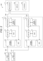
- an image inspection system 500 of a first embodiment includes two computers 1 and 2 as image inspection apparatuses, two scanners (a first scanner 3 and a second scanner 4) as readers, and a computer 5 as a report generator and an inspection result file generator.
- the image inspection system 500 can inspect an image on a printed matter 200 printed by one printer 6 as an image forming apparatus.
- the printer 6 outputs the printed matter 200 obtained by printing an image on a recording sheet.
- the printer 6 can be, for example, a one-pass (single-pass) inkjet printer, but is not limited thereto.
- the printed matter 200 is conveyed in a sub-scanning direction 201 (see Fig. 1 ) by a known conveyance mechanism (not illustrated).
- the sub-scanning direction 201 corresponds to a longitudinal direction of the printed matter 200.
- a main scanning direction corresponds to a lateral direction of the printed matter 200.
- the first scanner 3 and the second scanner 4 are a first reader and a second reader that optically read image data printed on the printed matter 200, respectively. Each of the first scanner 3 and the second scanner 4 functions as a reader that reads an image formed on the printed matter 200. The first scanner 3 and the second scanner 4 transmit read image data read from the printed matter 200 to the computers 1 and 2 via the buses 511 and 522, respectively.
- the first scanner 3 and the second scanner 4 read an image formed on the printed matter 200 as described above, the first scanner 3 and the second scanner 4 are arranged side by side in the main scanning direction. In addition, the first scanner 3 and the second scanner 4 are arranged above the conveyed printed matter 200 by a predetermined distance.
- the first scanner 3 scans a scan area 3A including a left half area of the printed matter 200. Specifically, a left end portion of the scan area 3A of the first scanner 3 is on the left of a left sheet end portion of the printed matter 200 by a predetermined number of pixels, and a right end portion of the scan area 3A is on the right of a central portion of a lateral width of the printed matter 200 by a predetermined number of pixels.
- the second scanner 4 scans a scan area 4A including a right half area of the printed matter 200. Specifically, a right end portion of the scan area 4A of the second scanner 4 is on the right of a right sheet end portion of the printed matter 200 by a predetermined number of pixels, and a left end portion of the scan area 4A is on the left of a central portion of a lateral width of the printed matter 200 by a predetermined number of pixels.
- the first scanner 3 and the second scanner 4 arranged side by side can acquire image data of the entire width of the printed matter 200.
- a central area of the printed matter 200 is scanned by both the first scanner 3 and the second scanner 4.
- Each of the computers 1 and 2 is an image inspection apparatus that inspects a defect of an image on the printed matter 200 output from the printer 6.
- the printed matter 200 is a recording medium on which an image is formed by the printer 6.
- the computer 1 is communicably connected to the first scanner 3 by the bus 511.
- the computer 2 is communicably connected to the second scanner 4 by the bus 512.
- the buses 511 and 522 are each, for example, a camera link, but are not limited thereto.
- the computer 1 compares read image data read from the left side of the printed matter 200 by the first scanner 3 with correct image data and inspects an image defect.
- the computer 2 compares read image data read from the right side of the printed matter 200 by the second scanner 4 with correct image data and inspects an image defect.
- computers 1 and 2 are communicably connected to the computer 5 by buses 533 and 544, respectively, and can exchange predetermined information with the computer 5.
- the computer 5 includes a report generator 51 and an inspection result file generator 52 described later. Since the computer 5 includes the report generator 51, the computer 5 generates a report (report data) based on image data acquired from the computers 1 and 2. Since the computer 5 includes the inspection result file generator 52, the computer 5 generates an inspection result file from a report (report data) created by the report generator 51.
- the left side of an image formed on each sheet is arranged on an odd page, and the right side of the image formed on each sheet is arranged on an even page.
- a user can view the inspection result file in a double-page spread manner, and therefore can suitably check the entire printed matter.
- the image inspection system 500 of the first embodiment includes the first scanner 3 and the second scanner 4.
- charge coupled device (CCD) line sensors 131 and 241 are used, respectively.
- a frame grabber 1a, a graphics processing unit (GPU) 1b, a chip set 1c, a solid state drive (SSD) Id, a processor 1e, and a double data rate 4 (DDR4) memory If are used as a hardware configuration of the computer 1.
- the frame grabber 1a is a dedicated assembly board having an image data input function.
- the frame grabber 1a acquires image data from the CCD line sensor 131 via the bus 511.
- the GPU 1b is a processor that performs calculation processing necessary for image depiction.
- the GPU 1b is in charge of an instruction related to image processing among instructions executed by the processor 1e.
- the chip set 1c is an IC chip that assists the processor 1e and controls data transmission between apparatuses and devices.
- the chip set 1c inputs output from the frame grabber 1a to the processor 1e.
- the SSD Id is an auxiliary storage device that handles a semiconductor memory like a disk drive.
- the SSD Id stores a predetermined program (including an image inspection program) executed by the processor 1e.
- the processor 1e is a central processing unit (CPU), and executes an instruction set described in a predetermined program. As a result, the processor 1e can implement each function according to the first embodiment.
- the processor 1e is a central processing unit of the computer 1, and executes a control program to implement functional units such as a first inspector 13 and a first generator 14 described later.
- the DDR4 memory If is a semiconductor memory capable of reading and writing.
- the DDR4 memory If is a work area of the processor 1e.
- a frame grabber 2a, a GPU 2b, a chip set 2c, an SSD 2d, a processor 2e, and a DDR4 memory 2f are used as a hardware configuration of the computer 2.
- the frame grabber 2a, the GPU 2b, the chip set 2c, the SSD 2d, the processor 2e, and the DDR4 memory 2f are the same as the frame grabber 1a, the GPU 1b, the chip set 1c, the SSD Id, the processor 1e, and the DDR4 memory If, respectively, and description thereof is omitted.
- the frame grabber 2a acquires image data from the CCD line sensor 241 via the bus 522.
- the processors 1e and 2e are connected to the computer 5 via the buses 533 and 544, respectively.
- the processor 2e is a central processing unit of the computer 2, and executes a control program to implement functional units such as a second inspector 23, a second generator 24, a first mirror processor 25, a second mirror processor 26, and a third mirror processor 20 described later.
- the computer 5 includes a processor 5a, a display 5b, a storage 5c, and the like.
- the processor 5e is a central processing unit (CPU), and executes an instruction set described in a predetermined program. As a result, the processor 5e can implement each function according to the first embodiment.
- the processor 5e is a central processing unit of the computer 5, and executes an image inspection program to implement functional units such as a report generator 51 and an inspection result file generator 52 described later.
- the display 5b is constituted by, for example, a liquid crystal display (LCD).
- the display 5b displays an inspection result file inspected by the computer 1 or 2. Note that the inspection result file is displayed not only on the computer 5, and may be displayed on any computer and viewed by a predetermined user.
- the storage 5c is a large-capacity storage device, and is constituted by, for example, a hard disk drive or a nonvolatile memory.
- the storage 120 stores, for example, an image inspection program, an inspection image, or a report.
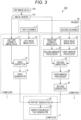
- Fig. 3 is a functional block diagram illustrating functions of the image inspection system 500 of the first embodiment.
- Raster image processor (RIP) image data 100 is stored in the printer 6 or a control device of the printer 6.
- the RIP image data 100 is image data in a bitmap format that can be printed by the printer 6 (image forming data used for image formation), and is, for example, a set of pixels indicated by CMYK values.
- An image divider 101 is included in, for example, the printer 6 or a control device (not illustrated) of the printer 6.
- the image divider 101 divides the RIP image data 100 used for printing by the printer 6 into left RIP correct image data 11 and right RIP correct image data 21 at a predetermined position in the main scanning direction. Then, the image divider 101 sends the left RIP correct image data 11 to the computer 1 and sends the right RIP correct image data 21 to the computer 2.
- the reader 30 reads an image formed on the printed matter 200 (recording medium).
- the reader 30 of the first embodiment includes the first scanner 3 and the second scanner 4 arranged at different positions in the main scanning direction with respect to the printed matter 200.
- the computer 1 of the first embodiment stores the left RIP correct image data 11 divided by the image divider 101 and left read image data 12 (first read image) acquired from the first scanner 3.
- the computer 1 includes the first inspector 13 and the first generator 14.
- the left RIP correct image data 11 is a left half of the RIP image data 100 used for image formation.
- the computer 1 receives the left RIP correct image data 11 divided by the image divider 101 from the image divider 101 and stores the left RIP correct image data 11.
- the left read image data 12 (first read image) is obtained by the first scanner 3 scanning a left half of the printed matter 200.
- the left read image data 12 includes one of divisions obtained by dividing the image formed on the printed matter 200 at a predetermined position in the main scanning direction.
- the predetermined position in the main scanning direction is any position where a scanning area by the first scanner 3 and a scanning area by the second scanner 4 overlap with each other, and is, for example, a center in a width direction of a printing area of the printed matter 200.
- the predetermined position in the main scanning direction is also a position obtained by projecting a position at which the image divider 101 divided the RIP image data 100 used for printing by the printer 6 onto a printing area of the printed matter 200.
- the first inspector 13 inspects the left read image data 12. Specifically, the first inspector 13 recognizes a left end of the printed matter 200 on the left side of the left read image data 12, and thus recognizes an image area of the printed matter 200. Then, the first inspector 13 compares the left RIP correct image data 11 with an image area of the left read image data 12, and detects an image defect of the left read image data 12. For example, the first inspector 13 determines whether or not a difference between a C (cyan) M (magenta) Y (yellow) K (black) value of a pixel at a predetermined position in the left read image data 12 and a CMYK value of a pixel at a corresponding position in the left RIP correct image data 11 falls within a predetermined range.
- the first inspector 13 determines that there is an image defect at the corresponding position of the left read image data 12.
- the first generator 14 generates first inspection image data (inspection image) related to the left read image data 12 (first read image) based on the inspection result of the first inspector 13.
- the computer 2 of the first embodiment stores the right RIP correct image data 21 divided by the image divider 101 and right read image data 22 (second read image) acquired from the second scanner 4.
- the computer 2 includes the second inspector 23, the second generator 24, the first mirror processor 25, the second mirror processor 26, and the third mirror processor 20.
- the right RIP correct image data 21 is a right half of the RIP image data 100 used for image formation.
- the computer 2 receives the right RIP correct image data 21 divided by the image divider 101 from the image divider 101 and stores the right RIP correct image data 21.
- the right read image data 22 (second read image) is obtained by the second scanner 4 scanning a right half of the printed matter 200.
- the right read image data 22 includes the other of the divisions obtained by dividing the image formed on the printed matter 200 at the predetermined position in the main scanning direction.
- the first mirror processor 25 of the computer 2 mirror-inverts the right read image data 22.
- the second mirror processor 26 of the computer 2 mirror-inverts the right RIP correct image data 21.
- detection processing in the second inspector 23 can be the same as detection processing in the first inspector 13 of the computer 1.
- the second inspector 23 inspects the right read image data 22. Specifically, the second inspector 23 recognizes a right end of the printed matter 200 on the left side of the mirror-inverted right read image data 22, and thus recognizes the image area of the printed matter 200. Then, the second inspector 23 compares the mirror-inverted right RIP correct image data 21 with the image area of the mirror-inverted right read image data 22, and detects an image defect of the mirror-inverted right read image data 22.
- the second inspector 23 determines whether or not a difference between a CMYK value of a pixel at a predetermined position in the mirror-inverted right read image data 22 and a CMYK value of a pixel at a corresponding position in the mirror-inverted right RIP correct image data 21 falls within a predetermined range.
- the second inspector 23 determines that there is an image defect at the corresponding position of the right read image data 22.
- the third mirror processor 20 mirror-inverts and returns the mirror-inverted second inspection image data to the original position, and changes the coordinates of the inspection data to the mirror-inverted position.
- the second inspector 23 needs to perform a mirror-inverted operation with respect to an operation of the first inspector 13, and it is necessary to create different detection programs between the second inspector 23 and the first inspector 13.
- an inspection program of the first inspector 13 and an inspection program of the second inspector 23 can be the same.
- first mirror processor 25, the second mirror processor 26, and the third mirror processor 20 are disposed in the computer 2, but may be disposed in the computer 1.
- the first mirror processor 25, the second mirror processor 26, and the third mirror processor 20 are optional components, and an operation of the second inspector 23 may be mirror-inversion with respect to an operation of the first inspector 13.
- the second generator 24 generates second inspection image data (inspection image) related to the right read image data 22 (second read image) based on the inspection result of the second inspector 23.
- the first generator 14 of the computer 1 and the second generator 24 of the computer 2 may add information regarding the order of the first inspection image data and the second inspection image data to the first inspection image data and the second inspection image data, respectively.
- the first generator 14 of the computer 1 and the second generator 24 of the computer 2 add information regarding the order to the first inspection image data and the second inspection image data, respectively such that the first inspection image data and the second inspection image data are continuous.
- the report generator 51 alternately arranges the first inspection image data and the second inspection image data in a report.
- the first generator 14 of the computer 1 and the second generator 24 of the computer 2 may add information regarding the order to the first inspection image data and the second inspection image data, respectively such that the first inspection image data and the second inspection image data are alternately continuous.
- the report generator 51 arranges the first inspection image data and the second inspection image data in a report based on the order information added to the first inspection image data and the second inspection image data.
- the first generator 14 of the computer 1 and the second generator 24 of the computer 2 can transmit pieces of the generated first inspection image data and pieces of the generated second inspection image data one by one, respectively.
- the first generator 14 and the second generator 24 may alternately transmit pieces of the first inspection image data and pieces of the second inspection image data one by one, respectively.
- the report generator 51 arranges the first inspection image data and the second inspection image data in a report in the order of reception.
- first generator 14 of the computer 1 and the second generator 24 of the computer 2 may collectively transmit a plurality of pieces of the first inspection image data and a plurality of pieces of the second inspection image data, respectively.
- the first generator 14 of the computer 1 and the second generator 24 of the computer 2 may add information regarding the reader 30 (the first scanner 3 and the second scanner 4) that has read the left read image data 12 or the right read image data 22 to the first inspection image data and/or the second inspection image data.
- the first generator 14 of the computer 1 and the second generator 24 of the computer 2 may generate the other image data.
- first inspection image data and the second inspection image data may include inspection results for the left read image data 12 and the right read image data 22, respectively.
- the inspection results include, for example, noise information and level information.
- the computer 5 of the first embodiment includes the report generator 51 and the inspection result file generator 52 described above.
- the report generator 51 alternately allocates (arranges) the first inspection image data and the second inspection image data in units of pages to generate a report (report data).
- the inspection result file generator 52 generates a file in a format such as a portable document format (PDF) from the report data in which the first inspection image data and the second inspection image data are alternately allocated in units of pages.
- PDF portable document format
- the first inspection image data and the second inspection image data constituting the report data are in a JPEG format.
- the inspection result file generator 52 integrates the plurality of pieces of first inspection image data and the plurality of pieces of second inspection image data into one PDF in the order of file names.
- Fig. 4 is an explanatory diagram illustrating a concept of a report including a result bookmark hierarchy.
- Each of images 300 and 320 illustrated in Fig. 4 is an image obtained by reading the printed matter 200 in units of pages.
- the image 300 includes an abnormality 301 and an abnormality 302.
- the abnormality 301 indicates a black streak
- the abnormality 302 indicates dirt
- the image 320 includes an abnormality 323.
- the abnormality 323 indicates a white streak.
- Inspection result data 310 is text data in which coordinates of an abnormal portion of the image 300 are described.
- Inspection result data 330 is text data in which coordinates of an abnormal portion of the image 320 are described.
- coordinates 333 of the abnormality 323 are described.
- Fig. 5 is a diagram illustrating a display example of an inspection result file including a result bookmark hierarchy.
- the inspection result file includes the inspection images illustrated in Fig. 4 and a result bookmark hierarchy superimposed on the inspection images.
- Information such as coordinates of an abnormal portion and the type of abnormality is stored in the result bookmark hierarchy.
- a PDF viewer displays a title or a balloon indicating the abnormality 301 at coordinates 311 and a title or a balloon indicating the abnormality 302 at coordinates 312 while the titles and the balloons are superimposed on the image 350.
- the PDF viewer displays a title or a balloon indicating the abnormality 323 at coordinates 333 while the title and the balloon are superimposed on the image 360.
- the report generator 51 allocates the inspection image data in a JPEG format and the inspection result data storing information such as the coordinates of an abnormal portion and the type of abnormality.
- the inspection result file generator 52 generates an inspection result file in which the coordinates of an abnormal portion, the type of abnormality, and the like are allocated to the result bookmark hierarchy, for example, in a PDF format while the inspection result file is superimposed on the inspection image data in a JPEG format.
- the PDF viewer can display a title or a balloon corresponding to the coordinates of the abnormal portion while the title and the balloon are superimposed on the inspection image.
- the format of the inspection result file is not limited to PDF. The viewer is not limited to the PDF viewer.
- Fig. 6 is an explanatory diagram illustrating an inspection result file obtained by combining inspection images.
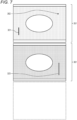
- Fig. 7 is an explanatory diagram illustrating an inspection result file obtained by combining inspection images only for an abnormal image in a read image.
- Each of Figs. 6 and 7 illustrates an inspection result file obtained by combining inspection images.
- an image 351 includes the abnormality 301 indicating a black streak and the abnormality 302 indicating dirt. Meanwhile, an image 361 includes the abnormality 323 indicating a white streak. Meanwhile, no abnormality is detected in an image 371.
- the image 351 and the image 361 are the same as those in Fig. 6 . However, since no abnormality is detected in the image 371 in Fig. 6 , the inspection result file illustrated in Fig. 7 does not include the image 371 in which no abnormality is detected.
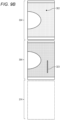
- Figs. 8A and 8B are each a diagram illustrating an inspection result file in which an inspection image is kept divided.
- Figs. 9A and 9B are each a diagram illustrating an inspection result file in which an inspection image is kept divided only for an abnormal image in a read image.
- an image 353 includes the abnormality 301 indicating a black streak. No abnormality is detected in an image 363. No abnormality is detected in an image 373. Since each of the images 353, 363, and 373 is a left half of one page, it is difficult to grasp the image quality and the like of the entire page of the printed matter 200.
- an image 354 includes the abnormality 302 indicating dirt.
- an image 364 includes the abnormality 323 indicating a white streak.
- no abnormality is detected in an image 374. Since each of the images 354, 364, and 374 is a right half of one page, it is difficult to grasp the image quality and the like of the entire page of the printed matter 200.
- the image 353 is the same as that in Fig. 8A .
- the inspection result file illustrated in Fig. 9A does not include the image 363 and the image 373 in which no abnormality is detected. Therefore, in this inspection result file, the image quality of the entire page of the printed matter 200 constituted by the images 363 and 364 or the images 373 and 374 cannot be grasped.
- the image 354 and the image 364 are the same as those in Fig. 8B .
- the inspection result file illustrated in Fig. 9B does not include the image 374. Therefore, in this inspection result file, the image quality of the entire page of the printed matter 200 constituted by the images 373 and 374 cannot be grasped.
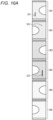
- Fig. 10A is a diagram illustrating an inspection result file generated by the image inspection system 500.
- the first inspection image data and the second inspection image data are arranged so as to be alternately continuous. Specifically, an image 381 of the first inspection image data including the page left side of a first printed matter 200 is arranged on a first page of the inspection result file. An image 382 of the second inspection image data including the page right side of the first printed matter 200 is arranged on a second page of the inspection result file.
- An image 383 of the first inspection image data including the page left side of a second printed matter 200 is arranged on a third page of the inspection result file.
- An image 384 of the second inspection image data including the page right side of the second printed matter 200 is arranged on a fourth page of the inspection result file.
- An image 385 of the first inspection image data including the page left side of a third printed matter 200 is arranged on a fifth page of the inspection result file.
- An image 386 of the second inspection image data including the page right side of the third printed matter 200 is arranged on a sixth page of the inspection result file.
- the first generator 14 adds information such that each of the images 381, 383, and 385 is arranged on the left side of an inspection image. For example, the first generator 14 assigns an odd number starting from 1 to a file name or a data name on the left side of a page of each printed matter 200.
- the second generator 24 of the computer 2 adds information regarding the order to the images 382, 384, and 386 which are the second inspection image data such that the first inspection image data and the second inspection image data are alternately continuous. Specifically, the second generator 24 adds information such that each of the images 382, 384, and 386 is arranged on the right side of an inspection image. For example, the second generator 24 assigns an even number starting from 2 to a file name or a data name on the right side of a page of each printed matter 200.
- the report generator 51 generates a report in which the left side of an image formed on each sheet is arranged on an odd page, and the right side of the image formed on each sheet is arranged on an even page.
- the inspection result file generator 52 generates an inspection result file from the report.
- the inspection result file is displayed by a PDF viewer such that each page of the first inspection image data and each page of the second inspection image data are alternately continuous.
- the image 381 includes the abnormality 301 indicating a black streak.
- the image 382 includes the abnormality 302 indicating dirt.
- the image 384 includes the abnormality 323 indicating a white streak.
- the report generator 51 of the computer 5 acquires the first inspection image data and the second inspection image data and generates a report (report data) in which the first inspection image data and the second inspection image data are alternately allocated (arranged).
- the inspection result file generator 52 generates an inspection result file, for example, in a PDF format from this report data. For example, when viewing the inspection result file, a user uses a double-page spread display function of a PDF viewer.
- Fig. 10B is a diagram illustrating an example in which an inspection result file is viewed in a double-page spread manner.
- a PDF viewer displays the inspection result file illustrated in Fig. 10A in a double-page spread manner. That is, the PDF viewer displays a first page and a second page of the inspection result file in a double-page spread manner, thereby displaying the image 381 of the first inspection image data including the page left side of a first printed matter 200 and the image 382 of the second inspection image data including the page right side of the first printed matter 200 in a double-page spread manner.
- the image 381 belonging to the first inspection image data is arranged on the first page of the inspection result file, and is therefore displayed on the left side in a double-page spread manner by the PDF viewer.
- the image 382 belonging to the second inspection image data is arranged on the second page of the inspection result file, and is therefore displayed on the right side in a double-page spread manner by the PDF viewer.
- the PDF viewer displays a third page and a fourth page of the inspection result file in a double-page spread manner, thereby displaying the image 383 of the first inspection image data including the page left side of a second printed matter 200 and the image 384 of the second inspection image data including the page right side of the second printed matter 200 in a double-page spread manner.
- the image 383 belonging to the first inspection image data is arranged on the third page of the inspection result file, and is therefore displayed on the left side in a double-page spread manner by the PDF viewer.
- the image 384 belonging to the second inspection image data is arranged on the fourth page of the inspection result file, and is therefore displayed on the right side in a double-page spread manner by the PDF viewer.
- the PDF viewer displays a fifth page and a sixth page of the inspection result file in a double-page spread manner, thereby displaying the image 385 of the first inspection image data including the page left side of a third printed matter 200 and the image 386 of the second inspection image data including the page right side of the third printed matter 200 in a double-page spread manner.
- the image 385 belonging to the first inspection image data is arranged on the fifth page of the inspection result file, and is therefore displayed on the left side in a double-page spread manner by the PDF viewer.
- the image 386 belonging to the second inspection image data is arranged on the sixth page of the inspection result file, and is therefore displayed on the right side in a double-page spread manner by the PDF viewer.
- the report generator 51 can generate and alternately arrange the first inspection image data and the second inspection image data in units of one page.
- first inspection image data and the second inspection image data may include inspection results for the left read image data 12 (first read image) and the right read image data 22 (second read image), respectively.
- the inspection results include, for example, noise information and level information.
- first generator 14 and the second generator 24 may add information regarding the reader that has read the left read image data 12 or the right read image data 22 to the first inspection image data and/or the second inspection image data.
- first generator 14 adds information of the first scanner 3 of the reader 30 to the first inspection image data.
- the second generator 24 adds information of the second scanner 4 of the reader 30 to the second inspection image data.
- the report generator 51 of the computer 5 generates a report in which the left side and the right side of an image formed on each sheet are alternately allocated.
- the entire page of the original printed matter can be viewed by a double-page spread display function of a PDF viewer (application for viewing).
- the image inspection system 500 can implement viewing substantially equivalent to a case of combining left and right inspection images and then generating a report.
- the image inspection system 500 can allocate each image such that a user can suitably view an inspection image and an inspection result report on the same sheet.
- the image inspection system 500 of the first embodiment includes the first scanner 3, the second scanner 4, the first inspector 13, the second inspector 23, the first generator 14, and the second generator 24.
- Each of the first scanner 3 and the second scanner 4 reads an image formed on the printed matter 200. That is, the first scanner 3 reads the left read image data 12 including one of divisions obtained by dividing the image on the printed matter 200 at a predetermined position in the main scanning direction. That is, the second scanner 4 reads the right read image data 22 including the other of the divisions obtained by dividing the image on the printed matter 200 at the predetermined position in the main scanning direction.
- the first inspector 13 inspects the left read image data 12 including one of divisions obtained by dividing the image at a predetermined position in the main scanning direction.
- the second inspector 23 inspects the right read image data 22 including the other of the divisions obtained by dividing the image at the predetermined position in the main scanning direction.
- the first generator 14 generates the first inspection image data (inspection image) related to the left read image data 12 based on the inspection result of the first inspector 13.
- the second generator 24 generates the second inspection image data (inspection image) related to the right read image data 22 based on the inspection result of the second inspector 23.
- the image inspection system 500 of the first embodiment can suitably generate an image inspection result in a case where a read image is divided in a sheet width direction, and can further solve a problem regarding generation of the image inspection result in a case where the read image is divided in the sheet width direction.
- the problem related to the generation of the image inspection result in a case where the read image is divided in the sheet width direction is, for example, checking the generated image inspection result in units of pages or creating a report of the image inspection result without deteriorating performance of the inspection.
- first generator 14 of the computer 1 and the second generator 24 of the computer 2 can add information regarding the order of the first inspection image data and the second inspection image data to the first inspection image data and the second inspection image data, respectively.
- the first generator 14 of the computer 1 and the second generator 24 of the computer 2 can add information regarding the order to the first inspection image data and the second inspection image data, respectively such that the first inspection image data and the second inspection image data are continuous.
- first generator 14 of the computer 1 and the second generator 24 of the computer 2 may add information regarding the order to the first inspection image data and the second inspection image data, respectively such that the first inspection image data and the second inspection image data are alternately continuous.
- first generator 14 and the second generator 24 may transmit pieces of the generated first inspection image data and pieces of the generated second inspection image data one by one, respectively. In this case, the first generator 14 and the second generator 24 may alternately transmit pieces of the first inspection image data and pieces of the second inspection image data one by one, respectively.
- first generator 14 and the second generator 24 may collectively transmit a plurality of pieces of the first inspection image data and a plurality of pieces of the second inspection image data, respectively.
- first generator 14 and the second generator 24 can generate the first inspection image data and the second inspection image data, respectively in a case where one of the first read image and the second read image includes an abnormality.
- first inspection image data and the second inspection image data can be arranged in a report so as to be displayed in a double-page spread manner all the time by a PDF viewer.
- the report includes an inspection image and an inspection result including an image defect portion and the type of defect.
- the report is generated for each of the left and right inspection images.
- the left and right inspection images are originally the inspection image obtained by analyzing an image on the same sheet, but a user views the report in which the image on the same sheet is divided into the left side and the right side. That is, there is a problem that it is difficult for the user to view the entire sheet.
- the image inspection system 500 of the first embodiment assigns each image such that a user can suitably view a report of a result of dividing an image formed on each sheet into two and inspecting the divided images. That is, the image inspection system 500 arranges the first inspection image data and the second inspection image data in the report such that the first inspection image data and the second inspection image data can be displayed in a double-page spread manner by a PDF viewer.
- the image inspection system 500 of the first embodiment can allow a user to suitably view an inspection image and an inspection result report on the same sheet.
- a report generator 51 of a computer 5 of a second embodiment generates a report such that the report does not include an inspection image in which each of left read image data 12 and right read image data 22 includes no abnormality. As a result, the number of pages and the data size of an inspection result file can be reduced.
- the report generator 51 of the second embodiment is different from the report generator 51 of the first embodiment in that two images 385 and 386 including no abnormality are not included in a report unlike Figs. 10A and 10B of the first embodiment.
- Fig. 11A is a diagram illustrating an inspection result file generated by the image inspection system 500.
- the inspection result file of Fig. 11A includes images 381 to 384 similarly to the inspection result file of Fig. 10A , but does not include images 385 and 386 constituting a page of a third printed matter 200 including no abnormality.
- the image 383 includes no abnormality, but a second printed matter 200 includes an abnormality 323. Therefore, the inspection result file includes the images 383 and 384 in order to display the entire page of the second printed matter 200 in a double-page spread manner.
- Fig. 11B is a diagram illustrating an example in which the inspection result file of Fig. 11A is viewed in a double-page spread manner.
- a PDF viewer displays the inspection result file illustrated in Fig. 11A in a double-page spread manner.
- the PDF viewer displays a first page and a second page of the inspection result file in a double-page spread manner, thereby displaying the image 381 of the first inspection image data including the page left side of a first printed matter 200 and the image 382 of the second inspection image data including the page right side of the first printed matter 200 in a double-page spread manner.
- a user can grasp the state of the entire page of the first printed matter 200 and grasp that the abnormalities 301 and 302 exist.
- the PDF viewer displays a third page and a fourth page of the inspection result file in a double-page spread manner, thereby displaying the image 383 of the first inspection image data including the page left side of a second printed matter 200 and the image 384 of the second inspection image data including the page right side of the second printed matter 200 in a double-page spread manner.
- a user can grasp the state of the entire page of the second printed matter 200 and grasp that the abnormality 323 exists.
- the inspection result file does not include the two images 385 and 386 each including no abnormality.
- the inspection result file can reduce the file size of the inspection result file.
- inspection image data of the printed matter 200 is excluded from the inspection result file.
- a user can view a combination of an odd page and an even page of the inspection result file in a double-page spread manner in association with any of the printed matters 200.
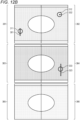
- An inspection result file of a third embodiment illustrated in Fig. 12A is obtained by combining inspection result data corresponding to images 381 to 386 (text data in which the coordinates of an abnormal portion are described) with the inspection result file of the first embodiment illustrated in Fig. 10A .
- a result bookmark hierarchy of the inspection result file can include coordinates 311 of an abnormality 301, coordinates 312 of an abnormality 302, and coordinates 333 of an abnormality 323.
- a PDF viewer can display a title or a balloon indicating an abnormality.
- Fig. 12B is a diagram illustrating an example in which the inspection result file of Fig. 12A is viewed in a double-page spread manner.
- a user can grasp the state of the entire page of a printed matter 200, can grasp that an abnormality exists, and can grasp the content of the abnormality by the title or the balloon.
- An inspection result file of a fourth embodiment illustrated in Fig. 13A is obtained by combining inspection result data corresponding to images 381 to 384 (text data in which the coordinates of an abnormal portion are described) with the inspection result file of the second embodiment illustrated in Fig. 11A .
- a result bookmark hierarchy of the inspection result file can include coordinates 311 of an abnormality 301, coordinates 312 of an abnormality 302, and coordinates 333 of an abnormality 323.
- a PDF viewer can display a title or a balloon indicating an abnormality.
- Fig. 13B is a diagram illustrating an example in which the inspection result file of Fig. 13A is viewed in a double-page spread manner.
- a user can grasp the state of the entire page of a printed matter 200, can grasp that an abnormality exists, and can grasp the content of the abnormality by the title or the balloon.
- the inspection result file can reduce the number of pages and the file size of the inspection result file.
- Fig. 14 is an overall configuration diagram of an image inspection system 501 of a fifth embodiment.
- a reader 31 of the image inspection system 501 includes a scanner 7 and an image divider 102 instead of the first scanner 3 and the second scanner 4 of the image inspection system 500 illustrated in the first embodiment.
- the scanner 7 reads an image formed on a printed matter 200.
- the scanner 7 has a longer length in a main scanning direction than the width of the printed matter 200, and can be read the image at one time.
- the image divider 102 divides the image read by the scanner 7 into left read image data 12 (first read image) and right read image data 22 (second read image) at a predetermined position in the main scanning direction.
- the image divider 102 can divide even an image read by one scanner 7. Therefore, the first inspector 13 and the second inspector 23 can inspect the left read image data 12 and the right read image data 22 in parallel, respectively.
- the image inspection system 501 of the fifth embodiment can exhibit similar effects to those of the image inspection system 500 described in the first to fourth embodiments.
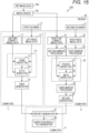
- Fig. 15 is an overall configuration diagram of an image inspection system 502 of a sixth embodiment. As illustrated in Fig. 15 , the image inspection system 502 includes a third inspector 17 and a fifth inspector 18 in a first inspector 13, and includes a fourth inspector 27 and a sixth inspector 28 in a second inspector 23.
- Each of the third inspector 17 and the fifth inspector 18 can generate an inspection image and inspection result data (text data in which the coordinates of an abnormal portion are described) in parallel.
- each of the fourth inspector 27 and the sixth inspector 28 can generate an inspection image and inspection result data (text data in which the coordinates of an abnormal portion are described) in parallel.
- the image inspection system 502 of the sixth embodiment can further improve performance of an inspection, and can perform image inspection even with a lower-speed computer.
- the first inspector 13 may include a plurality of inspectors
- the second inspector 23 may include a plurality of inspectors in the image inspection system 501 of the fifth embodiment.
Landscapes
- Engineering & Computer Science (AREA)
- Signal Processing (AREA)
- Multimedia (AREA)
- Health & Medical Sciences (AREA)
- Biomedical Technology (AREA)
- General Health & Medical Sciences (AREA)
- General Physics & Mathematics (AREA)
- Physics & Mathematics (AREA)
- Theoretical Computer Science (AREA)
- Computer Vision & Pattern Recognition (AREA)
- Quality & Reliability (AREA)
- Human Computer Interaction (AREA)
- Microelectronics & Electronic Packaging (AREA)
- Image Processing (AREA)
- Accessory Devices And Overall Control Thereof (AREA)
- Control Or Security For Electrophotography (AREA)
- Facsimiles In General (AREA)
- Facsimile Scanning Arrangements (AREA)
Abstract
Description
- The present invention relates to an image inspection apparatus, an image inspection method of the image inspection apparatus, and an image inspection system.
- As a technique related to an image inspection apparatus,
JP 2020-11472 A JP 2020-11472 A - A maximum sheet size of a normal electrophotographic printer is generally A3 size, which is 297 [mm] × 420 [mm]. Meanwhile, in a large one-pass inkjet machine, the maximum sheet size exceeds B2 (515 [mm] × 728 [mm]) and is 585 [mm] × 750 [mm].
- As an image reader for image inspection of a large printer, for example, there is an image reader that acquires a read image of the entire sheet width by a configuration in which two imaging units are connected to each other in parallel. This is because, in general, the configuration in which the two imaging units are connected to each other in parallel is often more advantageous in terms of cost than a case of adopting one imaging unit formed long in a main scanning direction. As a result, the image reader can read two read images divided in the sheet width direction.
- Here, two image processors analyze the two read images divided in the sheet width direction in parallel, respectively. In a case where two image processors process two read images in parallel, respectively, a processing speed only need to be a half of that in a case where a single read image is analyzed by one image processor, which is advantageous in terms of cost.
-
JP 2020-11472 A JP 2020-11472 A - Therefore, the present invention suitably generates an image inspection result in a case where a read image is divided in a sheet width direction.
- To achieve the abovementioned object, according to an aspect of the present invention, an image inspection apparatus reflecting one aspect of the present invention comprises:
- a reader that reads an image formed on a recording medium;
- a first inspector that inspects a first read image including one of divisions obtained by dividing the image at a predetermined position in a main scanning direction;
- a second inspector that inspects a second read image including the other of the divisions obtained by dividing the image;
- a first generator that generates first inspection image data related to the first read image based on an inspection result of the first inspector; and
- a second generator that generates second inspection image data related to the second read image based on an inspection result of the second inspector.
- The advantages and features provided by one or more embodiments of the invention will become more fully understood from the detailed description given hereinbelow and the appended drawings which are given by way of illustration only, and thus are not intended as a definition of the limits of the present invention:
-
Fig. 1 is an overall configuration diagram of an image inspection system of a first embodiment; -
Fig. 2 is a hardware configuration diagram of the image inspection system of the first embodiment; -
Fig. 3 is a functional block diagram illustrating functions of the image inspection system of the first embodiment; -
Fig. 4 is a diagram illustrating a report including a result bookmark hierarchy; -
Fig. 5 is a diagram illustrating a display example of an inspection result file including a result bookmark hierarchy; -
Fig. 6 is a diagram illustrating an inspection result file obtained by combining inspection images; -
Fig. 7 is a diagram illustrating an inspection result file obtained by combining inspection images only for an abnormal image in a read image; -
Fig. 8A is a diagram illustrating an inspection result file in which an inspection image is kept divided (part 1); -
Fig. 8B is a diagram illustrating an inspection result file in which an inspection image is kept divided (part 2); -
Fig. 9A is a diagram illustrating an inspection result file in which an inspection image is kept divided only for an abnormal image in a read image (part 1); -
Fig. 9B is a diagram illustrating an inspection result file in which an inspection image is kept divided only for an abnormal image in a read image (part 2); -
Fig. 10A is a diagram illustrating an inspection result file in which inspection images are alternately arranged while being divided; -
Fig. 10B is a screen example obtained by displaying an inspection result file in which inspection images are alternately arranged while being divided in a double-page spread manner; -
Fig. 11A is a diagram illustrating an inspection result file in which two images including no abnormality are not included and inspection images are alternately arranged while being divided, unlikeFig. 10A ; -
Fig. 11B is a diagram illustrating an inspection result file in which two images including no abnormality are not included and inspection images are alternately arranged while being divided, unlikeFig. 10B ; -
Fig. 12A is a diagram illustrating an inspection result file in which inspection images are alternately arranged while being divided and to which a result bookmark hierarchy is added; -
Fig. 12B is a screen example obtained by displaying an inspection result file in which inspection images are alternately arranged while being divided and to which a result bookmark hierarchy is added in a double-page spread manner; -
Fig. 13A is a diagram illustrating an inspection result file in which two images including no abnormality are not included and inspection images are alternately arranged while being divided, and to which a result bookmark hierarchy is added, unlikeFig. 11A ; -
Fig. 13B is a diagram illustrating an inspection result file in which two images including no abnormality are not included and inspection images are alternately arranged while being divided, and to which a result bookmark hierarchy is added, unlikeFig. 11B ; -
Fig. 14 is an overall configuration diagram of an image inspection system of a fifth embodiment; and -
Fig. 15 is an overall configuration diagram of an image inspection system of a sixth embodiment. - Hereinafter, one or more embodiments of the present invention will be described in detail with reference to the drawings. However, the scope of the invention is not limited to the disclosed embodiments. Note that the embodiments described below are examples for implementing the present invention, and should be appropriately modified or changed according to the configuration of an apparatus to which the present invention is applied and various conditions. In the drawings, the same components are denoted by the same reference numerals, and description thereof is omitted appropriately.
- As illustrated in
Fig. 1 , animage inspection system 500 of a first embodiment includes twocomputers first scanner 3 and a second scanner 4) as readers, and acomputer 5 as a report generator and an inspection result file generator. As a result, theimage inspection system 500 can inspect an image on a printedmatter 200 printed by oneprinter 6 as an image forming apparatus. - The
printer 6 outputs the printedmatter 200 obtained by printing an image on a recording sheet. Theprinter 6 can be, for example, a one-pass (single-pass) inkjet printer, but is not limited thereto. After being printed by theprinter 6, the printedmatter 200 is conveyed in a sub-scanning direction 201 (seeFig. 1 ) by a known conveyance mechanism (not illustrated). Thesub-scanning direction 201 corresponds to a longitudinal direction of the printedmatter 200. A main scanning direction corresponds to a lateral direction of the printedmatter 200. - The
first scanner 3 and thesecond scanner 4 are a first reader and a second reader that optically read image data printed on the printedmatter 200, respectively. Each of thefirst scanner 3 and thesecond scanner 4 functions as a reader that reads an image formed on the printedmatter 200. Thefirst scanner 3 and thesecond scanner 4 transmit read image data read from the printedmatter 200 to thecomputers buses - Since the
first scanner 3 and thesecond scanner 4 read an image formed on the printedmatter 200 as described above, thefirst scanner 3 and thesecond scanner 4 are arranged side by side in the main scanning direction. In addition, thefirst scanner 3 and thesecond scanner 4 are arranged above the conveyed printedmatter 200 by a predetermined distance. - Here, as the
first scanner 3 and thesecond scanner 4, for example, reduction optical system scanners can be adopted. Thefirst scanner 3 scans ascan area 3A including a left half area of the printedmatter 200. Specifically, a left end portion of thescan area 3A of thefirst scanner 3 is on the left of a left sheet end portion of the printedmatter 200 by a predetermined number of pixels, and a right end portion of thescan area 3A is on the right of a central portion of a lateral width of the printedmatter 200 by a predetermined number of pixels. - The
second scanner 4 scans ascan area 4A including a right half area of the printedmatter 200. Specifically, a right end portion of thescan area 4A of thesecond scanner 4 is on the right of a right sheet end portion of the printedmatter 200 by a predetermined number of pixels, and a left end portion of thescan area 4A is on the left of a central portion of a lateral width of the printedmatter 200 by a predetermined number of pixels. - Therefore, the
first scanner 3 and thesecond scanner 4 arranged side by side can acquire image data of the entire width of the printedmatter 200. A central area of the printedmatter 200 is scanned by both thefirst scanner 3 and thesecond scanner 4. - Each of the
computers matter 200 output from theprinter 6. The printedmatter 200 is a recording medium on which an image is formed by theprinter 6. Thecomputer 1 is communicably connected to thefirst scanner 3 by thebus 511. Thecomputer 2 is communicably connected to thesecond scanner 4 by the bus 512. Thebuses computer 1 compares read image data read from the left side of the printedmatter 200 by thefirst scanner 3 with correct image data and inspects an image defect. Thecomputer 2 compares read image data read from the right side of the printedmatter 200 by thesecond scanner 4 with correct image data and inspects an image defect. - In addition, the
computers computer 5 bybuses computer 5. - The
computer 5 includes areport generator 51 and an inspectionresult file generator 52 described later. Since thecomputer 5 includes thereport generator 51, thecomputer 5 generates a report (report data) based on image data acquired from thecomputers computer 5 includes the inspectionresult file generator 52, thecomputer 5 generates an inspection result file from a report (report data) created by thereport generator 51. - In the generated inspection result file, the left side of an image formed on each sheet is arranged on an odd page, and the right side of the image formed on each sheet is arranged on an even page. As a result, a user can view the inspection result file in a double-page spread manner, and therefore can suitably check the entire printed matter.
- As illustrated in
Fig. 1 , theimage inspection system 500 of the first embodiment includes thefirst scanner 3 and thesecond scanner 4. As thefirst scanner 3 and thesecond scanner 4, charge coupled device (CCD)line sensors image inspection system 500 of the first embodiment, aframe grabber 1a, a graphics processing unit (GPU) 1b, a chip set 1c, a solid state drive (SSD) Id, aprocessor 1e, and a double data rate 4 (DDR4) memory If are used as a hardware configuration of thecomputer 1. - The
frame grabber 1a is a dedicated assembly board having an image data input function. Theframe grabber 1a acquires image data from theCCD line sensor 131 via thebus 511. - The
GPU 1b is a processor that performs calculation processing necessary for image depiction. TheGPU 1b is in charge of an instruction related to image processing among instructions executed by theprocessor 1e. - The chip set 1c is an IC chip that assists the
processor 1e and controls data transmission between apparatuses and devices. The chip set 1c inputs output from theframe grabber 1a to theprocessor 1e. - The SSD Id is an auxiliary storage device that handles a semiconductor memory like a disk drive. The SSD Id stores a predetermined program (including an image inspection program) executed by the
processor 1e. - The
processor 1e is a central processing unit (CPU), and executes an instruction set described in a predetermined program. As a result, theprocessor 1e can implement each function according to the first embodiment. Theprocessor 1e is a central processing unit of thecomputer 1, and executes a control program to implement functional units such as afirst inspector 13 and afirst generator 14 described later. - The DDR4 memory If is a semiconductor memory capable of reading and writing. The DDR4 memory If is a work area of the
processor 1e. - In addition, in the
image inspection system 500 of the first embodiment, aframe grabber 2a, aGPU 2b, a chip set 2c, anSSD 2d, aprocessor 2e, and aDDR4 memory 2f are used as a hardware configuration of thecomputer 2. Theframe grabber 2a, theGPU 2b, the chip set 2c, theSSD 2d, theprocessor 2e, and theDDR4 memory 2f are the same as theframe grabber 1a, theGPU 1b, the chip set 1c, the SSD Id, theprocessor 1e, and the DDR4 memory If, respectively, and description thereof is omitted. - The
frame grabber 2a acquires image data from theCCD line sensor 241 via thebus 522. Theprocessors computer 5 via thebuses processor 2e is a central processing unit of thecomputer 2, and executes a control program to implement functional units such as asecond inspector 23, asecond generator 24, afirst mirror processor 25, asecond mirror processor 26, and athird mirror processor 20 described later. - The
computer 5 includes aprocessor 5a, adisplay 5b, astorage 5c, and the like. The processor 5e is a central processing unit (CPU), and executes an instruction set described in a predetermined program. As a result, the processor 5e can implement each function according to the first embodiment. The processor 5e is a central processing unit of thecomputer 5, and executes an image inspection program to implement functional units such as areport generator 51 and an inspectionresult file generator 52 described later. - The
display 5b is constituted by, for example, a liquid crystal display (LCD). Thedisplay 5b displays an inspection result file inspected by thecomputer computer 5, and may be displayed on any computer and viewed by a predetermined user. - The
storage 5c is a large-capacity storage device, and is constituted by, for example, a hard disk drive or a nonvolatile memory. The storage 120 stores, for example, an image inspection program, an inspection image, or a report. -
Fig. 3 is a functional block diagram illustrating functions of theimage inspection system 500 of the first embodiment. Raster image processor (RIP)image data 100 is stored in theprinter 6 or a control device of theprinter 6. As illustrated inFig. 3 , theRIP image data 100 is image data in a bitmap format that can be printed by the printer 6 (image forming data used for image formation), and is, for example, a set of pixels indicated by CMYK values. - An
image divider 101 is included in, for example, theprinter 6 or a control device (not illustrated) of theprinter 6. Theimage divider 101 divides theRIP image data 100 used for printing by theprinter 6 into left RIPcorrect image data 11 and right RIPcorrect image data 21 at a predetermined position in the main scanning direction. Then, theimage divider 101 sends the left RIPcorrect image data 11 to thecomputer 1 and sends the right RIPcorrect image data 21 to thecomputer 2. - The
reader 30 reads an image formed on the printed matter 200 (recording medium). Thereader 30 of the first embodiment includes thefirst scanner 3 and thesecond scanner 4 arranged at different positions in the main scanning direction with respect to the printedmatter 200. - The
computer 1 of the first embodiment stores the left RIPcorrect image data 11 divided by theimage divider 101 and left read image data 12 (first read image) acquired from thefirst scanner 3. Thecomputer 1 includes thefirst inspector 13 and thefirst generator 14. - The left RIP
correct image data 11 is a left half of theRIP image data 100 used for image formation. Thecomputer 1 receives the left RIPcorrect image data 11 divided by theimage divider 101 from theimage divider 101 and stores the left RIPcorrect image data 11. - The left read image data 12 (first read image) is obtained by the
first scanner 3 scanning a left half of the printedmatter 200. The left readimage data 12 includes one of divisions obtained by dividing the image formed on the printedmatter 200 at a predetermined position in the main scanning direction. Here, the predetermined position in the main scanning direction is any position where a scanning area by thefirst scanner 3 and a scanning area by thesecond scanner 4 overlap with each other, and is, for example, a center in a width direction of a printing area of the printedmatter 200. The predetermined position in the main scanning direction is also a position obtained by projecting a position at which theimage divider 101 divided theRIP image data 100 used for printing by theprinter 6 onto a printing area of the printedmatter 200. - The
first inspector 13 inspects the left readimage data 12. Specifically, thefirst inspector 13 recognizes a left end of the printedmatter 200 on the left side of the left readimage data 12, and thus recognizes an image area of the printedmatter 200. Then, thefirst inspector 13 compares the left RIPcorrect image data 11 with an image area of the left readimage data 12, and detects an image defect of the left readimage data 12. For example, thefirst inspector 13 determines whether or not a difference between a C (cyan) M (magenta) Y (yellow) K (black) value of a pixel at a predetermined position in the left readimage data 12 and a CMYK value of a pixel at a corresponding position in the left RIPcorrect image data 11 falls within a predetermined range. - In a case where the difference in CMYK value between the predetermined position in the left RIP
correct image data 11 and the corresponding position in the left readimage data 12 deviates from the predetermined range, thefirst inspector 13 determines that there is an image defect at the corresponding position of the left readimage data 12. - The
first generator 14 generates first inspection image data (inspection image) related to the left read image data 12 (first read image) based on the inspection result of thefirst inspector 13. - Meanwhile, the
computer 2 of the first embodiment stores the right RIPcorrect image data 21 divided by theimage divider 101 and right read image data 22 (second read image) acquired from thesecond scanner 4. Thecomputer 2 includes thesecond inspector 23, thesecond generator 24, thefirst mirror processor 25, thesecond mirror processor 26, and thethird mirror processor 20. - The right RIP
correct image data 21 is a right half of theRIP image data 100 used for image formation. Thecomputer 2 receives the right RIPcorrect image data 21 divided by theimage divider 101 from theimage divider 101 and stores the right RIPcorrect image data 21. - The right read image data 22 (second read image) is obtained by the
second scanner 4 scanning a right half of the printedmatter 200. The right readimage data 22 includes the other of the divisions obtained by dividing the image formed on the printedmatter 200 at the predetermined position in the main scanning direction. - The
first mirror processor 25 of thecomputer 2 mirror-inverts the right readimage data 22. Thesecond mirror processor 26 of thecomputer 2 mirror-inverts the right RIPcorrect image data 21. As a result, detection processing in thesecond inspector 23 can be the same as detection processing in thefirst inspector 13 of thecomputer 1. - The
second inspector 23 inspects the right readimage data 22. Specifically, thesecond inspector 23 recognizes a right end of the printedmatter 200 on the left side of the mirror-inverted right readimage data 22, and thus recognizes the image area of the printedmatter 200. Then, thesecond inspector 23 compares the mirror-inverted right RIPcorrect image data 21 with the image area of the mirror-inverted right readimage data 22, and detects an image defect of the mirror-inverted right readimage data 22. For example, thesecond inspector 23 determines whether or not a difference between a CMYK value of a pixel at a predetermined position in the mirror-inverted right readimage data 22 and a CMYK value of a pixel at a corresponding position in the mirror-inverted right RIPcorrect image data 21 falls within a predetermined range. - In a case where the difference in CMYK value between the predetermined position of the right RIP
correct image data 21 and the corresponding position of the right readimage data 22 deviates from the predetermined range, thesecond inspector 23 determines that there is an image defect at the corresponding position of the right readimage data 22. - Then, the
third mirror processor 20 mirror-inverts and returns the mirror-inverted second inspection image data to the original position, and changes the coordinates of the inspection data to the mirror-inverted position. - For example, in a case where the right read
image data 22 and the right RIPcorrect image data 21 are not mirror-inverted, thesecond inspector 23 needs to perform a mirror-inverted operation with respect to an operation of thefirst inspector 13, and it is necessary to create different detection programs between thesecond inspector 23 and thefirst inspector 13. In the first embodiment, since thefirst mirror processor 25, thesecond mirror processor 26, and thethird mirror processor 20 are disposed, an inspection program of thefirst inspector 13 and an inspection program of thesecond inspector 23 can be the same. - Note that the
first mirror processor 25, thesecond mirror processor 26, and thethird mirror processor 20 are disposed in thecomputer 2, but may be disposed in thecomputer 1. Thefirst mirror processor 25, thesecond mirror processor 26, and thethird mirror processor 20 are optional components, and an operation of thesecond inspector 23 may be mirror-inversion with respect to an operation of thefirst inspector 13. - The
second generator 24 generates second inspection image data (inspection image) related to the right read image data 22 (second read image) based on the inspection result of thesecond inspector 23. - The
first generator 14 of thecomputer 1 and thesecond generator 24 of thecomputer 2 may add information regarding the order of the first inspection image data and the second inspection image data to the first inspection image data and the second inspection image data, respectively. In this case, thefirst generator 14 of thecomputer 1 and thesecond generator 24 of thecomputer 2 add information regarding the order to the first inspection image data and the second inspection image data, respectively such that the first inspection image data and the second inspection image data are continuous. Thereport generator 51 alternately arranges the first inspection image data and the second inspection image data in a report. - Furthermore, the
first generator 14 of thecomputer 1 and thesecond generator 24 of thecomputer 2 may add information regarding the order to the first inspection image data and the second inspection image data, respectively such that the first inspection image data and the second inspection image data are alternately continuous. At this time, thereport generator 51 arranges the first inspection image data and the second inspection image data in a report based on the order information added to the first inspection image data and the second inspection image data. - In addition, the
first generator 14 of thecomputer 1 and thesecond generator 24 of thecomputer 2 can transmit pieces of the generated first inspection image data and pieces of the generated second inspection image data one by one, respectively. At this time, thefirst generator 14 and thesecond generator 24 may alternately transmit pieces of the first inspection image data and pieces of the second inspection image data one by one, respectively. Thereport generator 51 arranges the first inspection image data and the second inspection image data in a report in the order of reception. - In addition, the
first generator 14 of thecomputer 1 and thesecond generator 24 of thecomputer 2 may collectively transmit a plurality of pieces of the first inspection image data and a plurality of pieces of the second inspection image data, respectively. - In addition, the
first generator 14 of thecomputer 1 and thesecond generator 24 of thecomputer 2 may add information regarding the reader 30 (thefirst scanner 3 and the second scanner 4) that has read the left readimage data 12 or the right readimage data 22 to the first inspection image data and/or the second inspection image data. In a case where either the left readimage data 12 or the right readimage data 22 includes an abnormality, thefirst generator 14 of thecomputer 1 and thesecond generator 24 of thecomputer 2 may generate the other image data. - Note that the first inspection image data and the second inspection image data may include inspection results for the left read
image data 12 and the right readimage data 22, respectively. The inspection results include, for example, noise information and level information. - Meanwhile, the
computer 5 of the first embodiment includes thereport generator 51 and the inspectionresult file generator 52 described above. - The
report generator 51 alternately allocates (arranges) the first inspection image data and the second inspection image data in units of pages to generate a report (report data). - The inspection
result file generator 52 generates a file in a format such as a portable document format (PDF) from the report data in which the first inspection image data and the second inspection image data are alternately allocated in units of pages. In this case, for example, the first inspection image data and the second inspection image data constituting the report data are in a JPEG format. The inspectionresult file generator 52 integrates the plurality of pieces of first inspection image data and the plurality of pieces of second inspection image data into one PDF in the order of file names. -
Fig. 4 is an explanatory diagram illustrating a concept of a report including a result bookmark hierarchy. - Each of
images Fig. 4 is an image obtained by reading the printedmatter 200 in units of pages. - The
image 300 includes anabnormality 301 and anabnormality 302. Theabnormality 301 indicates a black streak, and theabnormality 302 indicates dirt. In addition, theimage 320 includes anabnormality 323. Theabnormality 323 indicates a white streak. -
Inspection result data 310 is text data in which coordinates of an abnormal portion of theimage 300 are described. Here, coordinates 311 of theabnormality 301 and coordinates 312 of theabnormality 302 are described.Inspection result data 330 is text data in which coordinates of an abnormal portion of theimage 320 are described. Here, coordinates 333 of theabnormality 323 are described. -
Fig. 5 is a diagram illustrating a display example of an inspection result file including a result bookmark hierarchy. - The inspection result file includes the inspection images illustrated in
Fig. 4 and a result bookmark hierarchy superimposed on the inspection images. Information such as coordinates of an abnormal portion and the type of abnormality is stored in the result bookmark hierarchy. - As illustrated in
Fig. 5 , a PDF viewer displays a title or a balloon indicating theabnormality 301 atcoordinates 311 and a title or a balloon indicating theabnormality 302 atcoordinates 312 while the titles and the balloons are superimposed on theimage 350. Similarly, the PDF viewer displays a title or a balloon indicating theabnormality 323 atcoordinates 333 while the title and the balloon are superimposed on theimage 360. - In this case, as illustrated in
Fig. 5 , thereport generator 51 allocates the inspection image data in a JPEG format and the inspection result data storing information such as the coordinates of an abnormal portion and the type of abnormality. The inspectionresult file generator 52 generates an inspection result file in which the coordinates of an abnormal portion, the type of abnormality, and the like are allocated to the result bookmark hierarchy, for example, in a PDF format while the inspection result file is superimposed on the inspection image data in a JPEG format. As a result, the PDF viewer can display a title or a balloon corresponding to the coordinates of the abnormal portion while the title and the balloon are superimposed on the inspection image. Note that the format of the inspection result file is not limited to PDF. The viewer is not limited to the PDF viewer. - Here, as a comparative example, a display example of an inspection result file obtained by combining conventional inspection images will be described. Note that the same components are denoted by the same reference numerals, and description thereof is omitted appropriately.
-
Fig. 6 is an explanatory diagram illustrating an inspection result file obtained by combining inspection images.Fig. 7 is an explanatory diagram illustrating an inspection result file obtained by combining inspection images only for an abnormal image in a read image. Each ofFigs. 6 and7 illustrates an inspection result file obtained by combining inspection images. - As illustrated in
Fig. 6 , animage 351 includes theabnormality 301 indicating a black streak and theabnormality 302 indicating dirt. Meanwhile, animage 361 includes theabnormality 323 indicating a white streak. Meanwhile, no abnormality is detected in animage 371. - As illustrated in
Fig. 7 , theimage 351 and theimage 361 are the same as those inFig. 6 . However, since no abnormality is detected in theimage 371 inFig. 6 , the inspection result file illustrated inFig. 7 does not include theimage 371 in which no abnormality is detected. -
Figs. 8A and8B are each a diagram illustrating an inspection result file in which an inspection image is kept divided.Figs. 9A and9B are each a diagram illustrating an inspection result file in which an inspection image is kept divided only for an abnormal image in a read image. - As illustrated in
Fig. 8A , animage 353 includes theabnormality 301 indicating a black streak. No abnormality is detected in animage 363. No abnormality is detected in animage 373. Since each of theimages matter 200. - As illustrated in
Fig. 8B , animage 354 includes theabnormality 302 indicating dirt. Meanwhile, animage 364 includes theabnormality 323 indicating a white streak. Meanwhile, no abnormality is detected in animage 374. Since each of theimages matter 200. - As illustrated in
Fig. 9A , theimage 353 is the same as that inFig. 8A . However, since no abnormality is detected in theimage 363 and theimage 373 inFig. 8A , the inspection result file illustrated inFig. 9A does not include theimage 363 and theimage 373 in which no abnormality is detected. Therefore, in this inspection result file, the image quality of the entire page of the printedmatter 200 constituted by theimages images - As illustrated in
Fig. 9B , theimage 354 and theimage 364 are the same as those inFig. 8B . However, since no abnormality is detected in theimage 374 inFig. 8B , the inspection result file illustrated inFig. 9B does not include theimage 374. Therefore, in this inspection result file, the image quality of the entire page of the printedmatter 200 constituted by theimages -
Fig. 10A is a diagram illustrating an inspection result file generated by theimage inspection system 500. - In the inspection result file illustrated in
Fig. 10A , the first inspection image data and the second inspection image data are arranged so as to be alternately continuous. Specifically, animage 381 of the first inspection image data including the page left side of a first printedmatter 200 is arranged on a first page of the inspection result file. Animage 382 of the second inspection image data including the page right side of the first printedmatter 200 is arranged on a second page of the inspection result file. - An
image 383 of the first inspection image data including the page left side of a second printedmatter 200 is arranged on a third page of the inspection result file. Animage 384 of the second inspection image data including the page right side of the second printedmatter 200 is arranged on a fourth page of the inspection result file. - An
image 385 of the first inspection image data including the page left side of a third printedmatter 200 is arranged on a fifth page of the inspection result file. Animage 386 of the second inspection image data including the page right side of the third printedmatter 200 is arranged on a sixth page of the inspection result file. - Returning to
Fig. 3 , the description will be continued. Thefirst generator 14 adds information such that each of theimages first generator 14 assigns an odd number starting from 1 to a file name or a data name on the left side of a page of each printedmatter 200. - Meanwhile, the
second generator 24 of thecomputer 2 adds information regarding the order to theimages second generator 24 adds information such that each of theimages second generator 24 assigns an even number starting from 2 to a file name or a data name on the right side of a page of each printedmatter 200. - As a result, the
report generator 51 generates a report in which the left side of an image formed on each sheet is arranged on an odd page, and the right side of the image formed on each sheet is arranged on an even page. Then, the inspectionresult file generator 52 generates an inspection result file from the report. As a result, the inspection result file is displayed by a PDF viewer such that each page of the first inspection image data and each page of the second inspection image data are alternately continuous. - Here, in the inspection result file illustrated in
Fig. 10A , theimage 381 includes theabnormality 301 indicating a black streak. Theimage 382 includes theabnormality 302 indicating dirt. - No abnormality is detected in the
image 383. Theimage 384 includes theabnormality 323 indicating a white streak. - No abnormality is detected in the
images - Returning to
Fig. 3 , the description will be continued. Thereport generator 51 of thecomputer 5 acquires the first inspection image data and the second inspection image data and generates a report (report data) in which the first inspection image data and the second inspection image data are alternately allocated (arranged). The inspectionresult file generator 52 generates an inspection result file, for example, in a PDF format from this report data. For example, when viewing the inspection result file, a user uses a double-page spread display function of a PDF viewer. -
Fig. 10B is a diagram illustrating an example in which an inspection result file is viewed in a double-page spread manner. - A PDF viewer displays the inspection result file illustrated in
Fig. 10A in a double-page spread manner. That is, the PDF viewer displays a first page and a second page of the inspection result file in a double-page spread manner, thereby displaying theimage 381 of the first inspection image data including the page left side of a first printedmatter 200 and theimage 382 of the second inspection image data including the page right side of the first printedmatter 200 in a double-page spread manner. - In this case, the
image 381 belonging to the first inspection image data is arranged on the first page of the inspection result file, and is therefore displayed on the left side in a double-page spread manner by the PDF viewer. Meanwhile, theimage 382 belonging to the second inspection image data is arranged on the second page of the inspection result file, and is therefore displayed on the right side in a double-page spread manner by the PDF viewer. - The PDF viewer displays a third page and a fourth page of the inspection result file in a double-page spread manner, thereby displaying the
image 383 of the first inspection image data including the page left side of a second printedmatter 200 and theimage 384 of the second inspection image data including the page right side of the second printedmatter 200 in a double-page spread manner. - In this case, the
image 383 belonging to the first inspection image data is arranged on the third page of the inspection result file, and is therefore displayed on the left side in a double-page spread manner by the PDF viewer. Meanwhile, theimage 384 belonging to the second inspection image data is arranged on the fourth page of the inspection result file, and is therefore displayed on the right side in a double-page spread manner by the PDF viewer. - Then, the PDF viewer displays a fifth page and a sixth page of the inspection result file in a double-page spread manner, thereby displaying the
image 385 of the first inspection image data including the page left side of a third printedmatter 200 and theimage 386 of the second inspection image data including the page right side of the third printedmatter 200 in a double-page spread manner. - In this case, the
image 385 belonging to the first inspection image data is arranged on the fifth page of the inspection result file, and is therefore displayed on the left side in a double-page spread manner by the PDF viewer. Meanwhile, theimage 386 belonging to the second inspection image data is arranged on the sixth page of the inspection result file, and is therefore displayed on the right side in a double-page spread manner by the PDF viewer. - In this manner, the
report generator 51 can generate and alternately arrange the first inspection image data and the second inspection image data in units of one page. - Note that the first inspection image data and the second inspection image data may include inspection results for the left read image data 12 (first read image) and the right read image data 22 (second read image), respectively. The inspection results include, for example, noise information and level information.
- In addition, the
first generator 14 and thesecond generator 24 may add information regarding the reader that has read the left readimage data 12 or the right readimage data 22 to the first inspection image data and/or the second inspection image data. For example, thefirst generator 14 adds information of thefirst scanner 3 of thereader 30 to the first inspection image data. Thesecond generator 24 adds information of thesecond scanner 4 of thereader 30 to the second inspection image data. - In this manner, the
report generator 51 of thecomputer 5 generates a report in which the left side and the right side of an image formed on each sheet are alternately allocated. In the inspection result file generated based on this report, the entire page of the original printed matter can be viewed by a double-page spread display function of a PDF viewer (application for viewing). - As a result, the
image inspection system 500 can implement viewing substantially equivalent to a case of combining left and right inspection images and then generating a report. In other words, theimage inspection system 500 can allocate each image such that a user can suitably view an inspection image and an inspection result report on the same sheet. - As described above, the
image inspection system 500 of the first embodiment includes thefirst scanner 3, thesecond scanner 4, thefirst inspector 13, thesecond inspector 23, thefirst generator 14, and thesecond generator 24. - Each of the
first scanner 3 and thesecond scanner 4 reads an image formed on the printedmatter 200. That is, thefirst scanner 3 reads the left readimage data 12 including one of divisions obtained by dividing the image on the printedmatter 200 at a predetermined position in the main scanning direction. That is, thesecond scanner 4 reads the right readimage data 22 including the other of the divisions obtained by dividing the image on the printedmatter 200 at the predetermined position in the main scanning direction. - The
first inspector 13 inspects the left readimage data 12 including one of divisions obtained by dividing the image at a predetermined position in the main scanning direction. Thesecond inspector 23 inspects the right readimage data 22 including the other of the divisions obtained by dividing the image at the predetermined position in the main scanning direction. Thefirst generator 14 generates the first inspection image data (inspection image) related to the left readimage data 12 based on the inspection result of thefirst inspector 13. Thesecond generator 24 generates the second inspection image data (inspection image) related to the right readimage data 22 based on the inspection result of thesecond inspector 23. - As a result, the
image inspection system 500 of the first embodiment can suitably generate an image inspection result in a case where a read image is divided in a sheet width direction, and can further solve a problem regarding generation of the image inspection result in a case where the read image is divided in the sheet width direction. The problem related to the generation of the image inspection result in a case where the read image is divided in the sheet width direction is, for example, checking the generated image inspection result in units of pages or creating a report of the image inspection result without deteriorating performance of the inspection. - Note that the
first generator 14 of thecomputer 1 and thesecond generator 24 of thecomputer 2 can add information regarding the order of the first inspection image data and the second inspection image data to the first inspection image data and the second inspection image data, respectively. - In this case, the
first generator 14 of thecomputer 1 and thesecond generator 24 of thecomputer 2 can add information regarding the order to the first inspection image data and the second inspection image data, respectively such that the first inspection image data and the second inspection image data are continuous. - Furthermore, the
first generator 14 of thecomputer 1 and thesecond generator 24 of thecomputer 2 may add information regarding the order to the first inspection image data and the second inspection image data, respectively such that the first inspection image data and the second inspection image data are alternately continuous. - In addition, the
first generator 14 and thesecond generator 24 may transmit pieces of the generated first inspection image data and pieces of the generated second inspection image data one by one, respectively. In this case, thefirst generator 14 and thesecond generator 24 may alternately transmit pieces of the first inspection image data and pieces of the second inspection image data one by one, respectively. - In addition, the
first generator 14 and thesecond generator 24 may collectively transmit a plurality of pieces of the first inspection image data and a plurality of pieces of the second inspection image data, respectively. - In addition, the
first generator 14 and thesecond generator 24 can generate the first inspection image data and the second inspection image data, respectively in a case where one of the first read image and the second read image includes an abnormality. As a result, the first inspection image data and the second inspection image data can be arranged in a report so as to be displayed in a double-page spread manner all the time by a PDF viewer. - Here, as described above, the report includes an inspection image and an inspection result including an image defect portion and the type of defect. In a case where the report is created based on an analysis result of an inspection image divided into the left side and the right side, the report is generated for each of the left and right inspection images. In this case, the left and right inspection images are originally the inspection image obtained by analyzing an image on the same sheet, but a user views the report in which the image on the same sheet is divided into the left side and the right side. That is, there is a problem that it is difficult for the user to view the entire sheet.
- Therefore, in order to make it easy for the user to view the entire sheet, it is conceivable to combine two read images on the left side and the right side on the same sheet and then perform inspection. However, since the area of the image to be analyzed is large, a higher-speed image processor is required.
- In addition, in order to make it easy for the user to view the entire sheet, it is also conceivable to combine two inspection images on the left side and the right side to create a report. However, when the report is created during an inspection, there is a concern that performance of the inspection is deteriorated. As a result, another image processor or a higher-speed image processor is required.
- Therefore, the
image inspection system 500 of the first embodiment assigns each image such that a user can suitably view a report of a result of dividing an image formed on each sheet into two and inspecting the divided images. That is, theimage inspection system 500 arranges the first inspection image data and the second inspection image data in the report such that the first inspection image data and the second inspection image data can be displayed in a double-page spread manner by a PDF viewer. - As a result, in a case where an image formed on the printed
matter 200 is divided into two and inspected, theimage inspection system 500 of the first embodiment can allow a user to suitably view an inspection image and an inspection result report on the same sheet. - A
report generator 51 of acomputer 5 of a second embodiment generates a report such that the report does not include an inspection image in which each of left readimage data 12 and right readimage data 22 includes no abnormality. As a result, the number of pages and the data size of an inspection result file can be reduced. - The
report generator 51 of the second embodiment is different from thereport generator 51 of the first embodiment in that twoimages Figs. 10A and10B of the first embodiment. -
Fig. 11A is a diagram illustrating an inspection result file generated by theimage inspection system 500. The inspection result file ofFig. 11A includesimages 381 to 384 similarly to the inspection result file ofFig. 10A , but does not includeimages matter 200 including no abnormality. Theimage 383 includes no abnormality, but a second printedmatter 200 includes anabnormality 323. Therefore, the inspection result file includes theimages matter 200 in a double-page spread manner. -
Fig. 11B is a diagram illustrating an example in which the inspection result file ofFig. 11A is viewed in a double-page spread manner. A PDF viewer displays the inspection result file illustrated inFig. 11A in a double-page spread manner. The PDF viewer displays a first page and a second page of the inspection result file in a double-page spread manner, thereby displaying theimage 381 of the first inspection image data including the page left side of a first printedmatter 200 and theimage 382 of the second inspection image data including the page right side of the first printedmatter 200 in a double-page spread manner. As a result, a user can grasp the state of the entire page of the first printedmatter 200 and grasp that theabnormalities - In addition, the PDF viewer displays a third page and a fourth page of the inspection result file in a double-page spread manner, thereby displaying the
image 383 of the first inspection image data including the page left side of a second printedmatter 200 and theimage 384 of the second inspection image data including the page right side of the second printedmatter 200 in a double-page spread manner. As a result, a user can grasp the state of the entire page of the second printedmatter 200 and grasp that theabnormality 323 exists. - In addition, the inspection result file does not include the two
images matter 200 from the inspection result file, the inspection result file can reduce the file size of the inspection result file. Furthermore, in a case where each of an inspection image on the left side and an inspection image on the right side on the printedmatter 200 includes no abnormality, inspection image data of the printedmatter 200 is excluded from the inspection result file. As a result, a user can view a combination of an odd page and an even page of the inspection result file in a double-page spread manner in association with any of the printed matters 200. - An inspection result file of a third embodiment illustrated in
Fig. 12A is obtained by combining inspection result data corresponding toimages 381 to 386 (text data in which the coordinates of an abnormal portion are described) with the inspection result file of the first embodiment illustrated inFig. 10A . As a result, a result bookmark hierarchy of the inspection result file can includecoordinates 311 of anabnormality 301, coordinates 312 of anabnormality 302, and coordinates 333 of anabnormality 323. - By combining the inspection result data with the result bookmark hierarchy of the inspection result file, a PDF viewer can display a title or a balloon indicating an abnormality.
-
Fig. 12B is a diagram illustrating an example in which the inspection result file ofFig. 12A is viewed in a double-page spread manner. As a result, a user can grasp the state of the entire page of a printedmatter 200, can grasp that an abnormality exists, and can grasp the content of the abnormality by the title or the balloon. - An inspection result file of a fourth embodiment illustrated in
Fig. 13A is obtained by combining inspection result data corresponding toimages 381 to 384 (text data in which the coordinates of an abnormal portion are described) with the inspection result file of the second embodiment illustrated inFig. 11A . As a result, a result bookmark hierarchy of the inspection result file can includecoordinates 311 of anabnormality 301, coordinates 312 of anabnormality 302, and coordinates 333 of anabnormality 323. - By combining the inspection result data with the result bookmark hierarchy of the inspection result file, a PDF viewer can display a title or a balloon indicating an abnormality.
-
Fig. 13B is a diagram illustrating an example in which the inspection result file ofFig. 13A is viewed in a double-page spread manner. As a result, a user can grasp the state of the entire page of a printedmatter 200, can grasp that an abnormality exists, and can grasp the content of the abnormality by the title or the balloon. Furthermore, by excluding a left inspection image and a right inspection image of a third printedmatter 200 including no abnormality, the inspection result file can reduce the number of pages and the file size of the inspection result file. -
Fig. 14 is an overall configuration diagram of animage inspection system 501 of a fifth embodiment. As illustrated inFig. 14 , areader 31 of theimage inspection system 501 includes ascanner 7 and animage divider 102 instead of thefirst scanner 3 and thesecond scanner 4 of theimage inspection system 500 illustrated in the first embodiment. - The
scanner 7 reads an image formed on a printedmatter 200. For example, thescanner 7 has a longer length in a main scanning direction than the width of the printedmatter 200, and can be read the image at one time. - The
image divider 102 divides the image read by thescanner 7 into left read image data 12 (first read image) and right read image data 22 (second read image) at a predetermined position in the main scanning direction. - As a result, the
image divider 102 can divide even an image read by onescanner 7. Therefore, thefirst inspector 13 and thesecond inspector 23 can inspect the left readimage data 12 and the right readimage data 22 in parallel, respectively. - Therefore, the
image inspection system 501 of the fifth embodiment can exhibit similar effects to those of theimage inspection system 500 described in the first to fourth embodiments. -
Fig. 15 is an overall configuration diagram of animage inspection system 502 of a sixth embodiment. As illustrated inFig. 15 , theimage inspection system 502 includes athird inspector 17 and afifth inspector 18 in afirst inspector 13, and includes afourth inspector 27 and asixth inspector 28 in asecond inspector 23. - To the
third inspector 17 and thefifth inspector 18, for example, inspectors that perform analysis according to an inspection item are assigned. Each of thethird inspector 17 and thefifth inspector 18 can generate an inspection image and inspection result data (text data in which the coordinates of an abnormal portion are described) in parallel. - Meanwhile, similarly to the
third inspector 17 and thefifth inspector 18, to thefourth inspector 27 and thesixth inspector 28, for example, inspectors that perform analysis according to an inspection item are assigned. Each of thefourth inspector 27 and thesixth inspector 28 can generate an inspection image and inspection result data (text data in which the coordinates of an abnormal portion are described) in parallel. - As a result, the
image inspection system 502 of the sixth embodiment can further improve performance of an inspection, and can perform image inspection even with a lower-speed computer. Furthermore, in theimage inspection system 502 of the sixth embodiment, thefirst inspector 13 may include a plurality of inspectors, and thesecond inspector 23 may include a plurality of inspectors in theimage inspection system 501 of the fifth embodiment. - Although embodiments of the present invention have been described and illustrated in detail, the disclosed embodiments are made for purposes of illustration and example only and not limitation. The scope of the present invention should be interpreted by terms of the appended claims.
Claims (15)
- An image inspection apparatus comprising:a reader (30) that reads an image formed on a recording medium;a first inspector (13) that inspects a first read image (12) including one of divisions obtained by dividing the image at a predetermined position in a main scanning direction;a second inspector (23) that inspects a second read image (22) including the other of the divisions obtained by dividing the image;a first generator (14) that generates first inspection image data related to the first read image (12) based on an inspection result of the first inspector (13); anda second generator (24) that generates second inspection image data related to the second read image (22) based on an inspection result of the second inspector (23).
- The image inspection apparatus according to claim 1, wherein
the reader (30) includes a first reader (3) and a second reader (4) arranged at different positions in the main scanning direction with respect to the recording medium. - The image inspection apparatus according to claim 1, wherein
the reader (30) further includes an image divider (101) that divides the image read from the recording medium into the first read image (12) and the second read image (22) at a predetermined position in the main scanning direction. - The image inspection apparatus according to any one of claims 1 to 3, whereinthe first generator (14) and the second generator (24)add information regarding an order of the first inspection image data and the second inspection image data to the first inspection image data and the second inspection image data, respectively.
- The image inspection apparatus according to claim 4, whereinthe first generator (14) and the second generator (24)add the information regarding the order to the first inspection image data and the second inspection image data, respectively such that the first inspection image data and the second inspection image data are continuous.
- The image inspection apparatus according to claim 5, whereinthe first generator (14) and the second generator (24)add the information regarding the order to the first inspection image data and the second inspection image data, respectively such that the first inspection image data and the second inspection image data are alternately continuous.
- The image inspection apparatus according to any one of claims 1 to 6, comprising
a report generator (51) that generates a report in which the first inspection image data and the second inspection image data are alternately arranged in units of pages. - The image inspection apparatus according to claim 7, whereinthe first inspection image data and the second inspection image dataare displayed in a double-page spread manner by a viewer in correspondence with arrangement of the first read image (12) and the second read image (22).
- The image inspection apparatus according to claim 7 or 8, whereinthe report generator (51)generates the first inspection image data and the second inspection image data in units of one page and alternately allocates the first inspection image data and the second inspection image data.
- The image inspection apparatus according to any one of claims 1 to 9, whereinthe first inspection image data and the second inspection image datainclude inspection results for the first read image (12) and the second read image (22), respectively.
- The image inspection apparatus according to any one of claims 1 to 10, whereinin a case where either the first read image (12) or the second read image (22) includes an abnormality,the first generator (14) and the second generator (24) generate the other read image.
- The image inspection apparatus according to claim 1, whereinthe first generator (14) and the second generator (24)add information regarding the reader (30) that has read the first read image (12) or the second read image (22) to the first inspection image data and/or the second inspection image data.
- The image inspection apparatus according to claim 1, wherein
one of the first inspector (13) and the second inspector (23) further includes:a first mirror processor (25) that mirror-inverts the first read image (12) or the second read image (22);a second mirror processor (26) that mirror-inverts correct image data corresponding to the inverted first read image (12) or the inverted second read image (22); anda third mirror processor (20) that mirror-inverts an inspection result of the second inspector (23), andthe first inspector (13) and the second inspector (23)compare the first read image (12) and the second read image (22) with correct image data for inspection, respectively. - An image inspection method of an image inspection apparatus, the method comprising:reading an image formed on a recording medium;inspecting a first read image (12) including one of divisions obtained by dividing the image at a predetermined position in a main scanning direction;inspecting a second read image (22) including the other of the divisions obtained by dividing the image;generating first inspection image data related to the first read image (12) based on an inspection result of the first read image (12); andgenerating second inspection image data related to the second read image (22) based on an inspection result of the second read image (22).
- An image inspection system (500) comprising:a reader (30) that reads an image formed on a recording medium;a first inspector (13) that inspects a first read image (12) including one of divisions obtained by dividing the image at a predetermined position in a main scanning direction;a second inspector (23) that inspects a second read image (22) including the other of the divisions obtained by dividing the image;a first generator (14) that generates first inspection image data related to the first read image (12) based on an inspection result of the first inspector (13);a second generator (24) that generates second inspection image data related to the second read image (22) based on an inspection result of the second inspector (23); anda report generator (51) that generates a report in which the first inspection image data and the second inspection image data are alternately arranged in units of pages.
Applications Claiming Priority (1)
| Application Number | Priority Date | Filing Date | Title |
|---|---|---|---|
| JP2021178606A JP7790095B2 (en) | 2021-11-01 | 2021-11-01 | Image inspection device, image inspection system, and image inspection program |
Publications (1)
| Publication Number | Publication Date |
|---|---|
| EP4175271A1 true EP4175271A1 (en) | 2023-05-03 |
Family
ID=83996763
Family Applications (1)
| Application Number | Title | Priority Date | Filing Date |
|---|---|---|---|
| EP22203467.0A Pending EP4175271A1 (en) | 2021-11-01 | 2022-10-25 | Image inspection apparatus, image inspection method of image inspection apparatus, and image inspection system |
Country Status (4)
| Country | Link |
|---|---|
| US (1) | US12450725B2 (en) |
| EP (1) | EP4175271A1 (en) |
| JP (1) | JP7790095B2 (en) |
| CN (1) | CN116074449A (en) |
Citations (4)
| Publication number | Priority date | Publication date | Assignee | Title |
|---|---|---|---|---|
| JP2020011472A (en) | 2018-07-19 | 2020-01-23 | コニカミノルタ株式会社 | Image inspection device, program and image formation device |
| US20200051231A1 (en) * | 2018-08-13 | 2020-02-13 | Konica Minolta, Inc. | Image inspection device, image forming device, and computer-readable recording medium storing a program |
| US20200322492A1 (en) * | 2019-04-08 | 2020-10-08 | Konica Minolta, Inc. | Inspection system, inspection method, and inspection program |
| JP2021063673A (en) * | 2019-10-11 | 2021-04-22 | コニカミノルタ株式会社 | Image data inspection device, image data inspection method, and image inspection program |
Family Cites Families (7)
| Publication number | Priority date | Publication date | Assignee | Title |
|---|---|---|---|---|
| JP2000172844A (en) * | 1998-12-03 | 2000-06-23 | Toshiba Corp | Print inspection method and print inspection device |
| JP4882926B2 (en) * | 2007-08-31 | 2012-02-22 | セイコーエプソン株式会社 | Image data processing apparatus and image data processing method |
| JP6273932B2 (en) * | 2014-03-14 | 2018-02-07 | 株式会社リコー | Image inspection apparatus, image inspection system, and image inspection program |
| JP2017176202A (en) * | 2016-03-28 | 2017-10-05 | コニカミノルタ株式会社 | Dynamics analysis system |
| JP6862674B2 (en) * | 2016-04-19 | 2021-04-21 | コニカミノルタ株式会社 | Inkjet recording device |
| JP6665671B2 (en) * | 2016-05-11 | 2020-03-13 | コニカミノルタ株式会社 | Image inspection apparatus, image forming apparatus, and program |
| JP2018170734A (en) * | 2017-03-30 | 2018-11-01 | キヤノン株式会社 | Image forming apparatus and image forming method |
-
2021
- 2021-11-01 JP JP2021178606A patent/JP7790095B2/en active Active
-
2022
- 2022-10-25 EP EP22203467.0A patent/EP4175271A1/en active Pending
- 2022-10-26 US US18/049,629 patent/US12450725B2/en active Active
- 2022-10-28 CN CN202211334539.1A patent/CN116074449A/en active Pending
Patent Citations (4)
| Publication number | Priority date | Publication date | Assignee | Title |
|---|---|---|---|---|
| JP2020011472A (en) | 2018-07-19 | 2020-01-23 | コニカミノルタ株式会社 | Image inspection device, program and image formation device |
| US20200051231A1 (en) * | 2018-08-13 | 2020-02-13 | Konica Minolta, Inc. | Image inspection device, image forming device, and computer-readable recording medium storing a program |
| US20200322492A1 (en) * | 2019-04-08 | 2020-10-08 | Konica Minolta, Inc. | Inspection system, inspection method, and inspection program |
| JP2021063673A (en) * | 2019-10-11 | 2021-04-22 | コニカミノルタ株式会社 | Image data inspection device, image data inspection method, and image inspection program |
Also Published As
| Publication number | Publication date |
|---|---|
| US12450725B2 (en) | 2025-10-21 |
| JP2023067408A (en) | 2023-05-16 |
| CN116074449A (en) | 2023-05-05 |
| US20230132446A1 (en) | 2023-05-04 |
| JP7790095B2 (en) | 2025-12-23 |
Similar Documents
| Publication | Publication Date | Title |
|---|---|---|
| US9007658B2 (en) | Inspection apparatus, inspection method, and program | |
| US10489091B2 (en) | Image forming apparatus, inspection device, and inspection program | |
| JP2020026091A (en) | Image inspection device, image forming device, and program | |
| US20210082100A1 (en) | Image inspection apparatus, image inspection method, and image inspection program | |
| US20200250805A1 (en) | Image inspection device, image formation device, image inspection method, and non-transitory recording medium storing a computer readable program | |
| US12462374B2 (en) | Image processing apparatus, image processing method, and non-transitory computer-readable storage medium | |
| JP2021158584A (en) | Image processing equipment, image processing methods and programs | |
| JP2021107788A (en) | Inspection device, insection method and program | |
| JP2023122792A (en) | Print inspection system and program | |
| US12086482B2 (en) | Overprinting inspection apparatus and non-transitory computer readable medium storing overprinting inspection program | |
| US12450725B2 (en) | Image inspection apparatus, image inspection method of image inspection apparatus, and image inspection system | |
| JP4510847B2 (en) | Image processing apparatus and image processing program | |
| US11863716B2 (en) | Image forming apparatus including printer and readers | |
| JP2021045866A (en) | Image inspection system, image inspection method, and image inspection program | |
| US20110216337A1 (en) | Image processing apparatus, image processing system, and computer readable medium | |
| US8331736B2 (en) | Image processing device and method therefor | |
| US12450727B2 (en) | Image processing apparatus, image processing method, and medium that obtains a difference in color information at corresponding positions between a composite image and a print image | |
| US12050818B2 (en) | Image processing apparatus, image processing method, and storage medium for inspecting a printed image | |
| US12394034B2 (en) | Inspecting print quality of a print product with coordinate information acquired without printing the image data | |
| CN118032798A (en) | Print inspection system and computer readable medium | |
| US12423543B2 (en) | Inspection system, inspection apparatus, and method of controlling these | |
| US20240095904A1 (en) | Image processing apparatus, image processing method, and non-transitory computer readable medium | |
| US20090116045A1 (en) | System and method for driver-based image manipulation | |
| JP2021063673A (en) | Image data inspection device, image data inspection method, and image inspection program | |
| JP7581849B2 (en) | Print inspection device, image forming device, program, and print inspection system |
Legal Events
| Date | Code | Title | Description |
|---|---|---|---|
| PUAI | Public reference made under article 153(3) epc to a published international application that has entered the european phase |
Free format text: ORIGINAL CODE: 0009012 |
|
| STAA | Information on the status of an ep patent application or granted ep patent |
Free format text: STATUS: THE APPLICATION HAS BEEN PUBLISHED |
|
| AK | Designated contracting states |
Kind code of ref document: A1 Designated state(s): AL AT BE BG CH CY CZ DE DK EE ES FI FR GB GR HR HU IE IS IT LI LT LU LV MC ME MK MT NL NO PL PT RO RS SE SI SK SM TR |
|
| STAA | Information on the status of an ep patent application or granted ep patent |
Free format text: STATUS: REQUEST FOR EXAMINATION WAS MADE |
|
| 17P | Request for examination filed |
Effective date: 20231030 |
|
| RBV | Designated contracting states (corrected) |
Designated state(s): AL AT BE BG CH CY CZ DE DK EE ES FI FR GB GR HR HU IE IS IT LI LT LU LV MC ME MK MT NL NO PL PT RO RS SE SI SK SM TR |
|
| STAA | Information on the status of an ep patent application or granted ep patent |
Free format text: STATUS: EXAMINATION IS IN PROGRESS |
|
| 17Q | First examination report despatched |
Effective date: 20250925 |
|
| GRAP | Despatch of communication of intention to grant a patent |
Free format text: ORIGINAL CODE: EPIDOSNIGR1 |
|
| STAA | Information on the status of an ep patent application or granted ep patent |
Free format text: STATUS: GRANT OF PATENT IS INTENDED |
|
| INTG | Intention to grant announced |
Effective date: 20260211 |
|
| GRAS | Grant fee paid |
Free format text: ORIGINAL CODE: EPIDOSNIGR3 |
|
| GRAA | (expected) grant |
Free format text: ORIGINAL CODE: 0009210 |
|
| STAA | Information on the status of an ep patent application or granted ep patent |
Free format text: STATUS: THE PATENT HAS BEEN GRANTED |