EP4175192A1 - Apparatus and method for beam failure recovery in mobile communications - Google Patents
Apparatus and method for beam failure recovery in mobile communications Download PDFInfo
- Publication number
- EP4175192A1 EP4175192A1 EP22202232.9A EP22202232A EP4175192A1 EP 4175192 A1 EP4175192 A1 EP 4175192A1 EP 22202232 A EP22202232 A EP 22202232A EP 4175192 A1 EP4175192 A1 EP 4175192A1
- Authority
- EP
- European Patent Office
- Prior art keywords
- referred
- following
- csi
- network node
- configuration
- Prior art date
- Legal status (The legal status is an assumption and is not a legal conclusion. Google has not performed a legal analysis and makes no representation as to the accuracy of the status listed.)
- Pending
Links
Images


Classifications
-
- H—ELECTRICITY
- H04—ELECTRIC COMMUNICATION TECHNIQUE
- H04B—TRANSMISSION
- H04B7/00—Radio transmission systems, i.e. using radiation field
- H04B7/02—Diversity systems; Multi-antenna system, i.e. transmission or reception using multiple antennas
- H04B7/04—Diversity systems; Multi-antenna system, i.e. transmission or reception using multiple antennas using two or more spaced independent antennas
- H04B7/06—Diversity systems; Multi-antenna system, i.e. transmission or reception using multiple antennas using two or more spaced independent antennas at the transmitting station
- H04B7/0686—Hybrid systems, i.e. switching and simultaneous transmission
- H04B7/0695—Hybrid systems, i.e. switching and simultaneous transmission using beam selection
- H04B7/06952—Selecting one or more beams from a plurality of beams, e.g. beam training, management or sweeping
- H04B7/06964—Re-selection of one or more beams after beam failure
-
- H—ELECTRICITY
- H04—ELECTRIC COMMUNICATION TECHNIQUE
- H04B—TRANSMISSION
- H04B7/00—Radio transmission systems, i.e. using radiation field
- H04B7/02—Diversity systems; Multi-antenna system, i.e. transmission or reception using multiple antennas
- H04B7/04—Diversity systems; Multi-antenna system, i.e. transmission or reception using multiple antennas using two or more spaced independent antennas
- H04B7/08—Diversity systems; Multi-antenna system, i.e. transmission or reception using multiple antennas using two or more spaced independent antennas at the receiving station
- H04B7/0868—Hybrid systems, i.e. switching and combining
- H04B7/088—Hybrid systems, i.e. switching and combining using beam selection
-
- H—ELECTRICITY
- H04—ELECTRIC COMMUNICATION TECHNIQUE
- H04L—TRANSMISSION OF DIGITAL INFORMATION, e.g. TELEGRAPHIC COMMUNICATION
- H04L5/00—Arrangements affording multiple use of the transmission path
- H04L5/003—Arrangements for allocating sub-channels of the transmission path
- H04L5/0048—Allocation of pilot signals, i.e. of signals known to the receiver
- H04L5/0051—Allocation of pilot signals, i.e. of signals known to the receiver of dedicated pilots, i.e. pilots destined for a single user or terminal
-
- H—ELECTRICITY
- H04—ELECTRIC COMMUNICATION TECHNIQUE
- H04W—WIRELESS COMMUNICATION NETWORKS
- H04W24/00—Supervisory, monitoring or testing arrangements
- H04W24/04—Arrangements for maintaining operational condition
Definitions
- the disclosed embodiments relate generally to wireless communication, and, more particularly, to channel state information-reference signal (CSI-RS) associated with serving transmission configuration indication (TCI) in mobile communications.
- CSI-RS channel state information-reference signal
- TCI serving transmission configuration indication
- LTE long-term evolution
- 4G long-term evolution
- LTE systems also known as the 4G system
- an evolved universal terrestrial radio access network includes a plurality of evolved Node-Bs (eNodeBs or eNBs) communicating with a plurality of mobile stations, referred to as user equipments (UEs).
- UEs user equipments
- 3GPP 3 rd generation partner project
- 3GPP 3 rd generation partner project
- the next generation mobile network (NGMN) board has decided to focus the future NGMN activities on defining the end-to-end requirements for 5G new radio (NR) systems.
- NGMN next generation mobile network
- BFR beam failure recovery
- TCI serving transmission configuration indication
- PDCH UE-dedicated physical downlink control channel
- PDSCH UE-dedicated physical downlink shared channel
- the network node may allocate channel state information (CSI) configuration for the user equipment (UE).
- the CSI configuration may comprise at least one CSI-reference signal (CSI-RS) associated with a serving transmission configuration indication (TCI) for the UE.
- the network node may transmit the CSI configuration to the UE.
- the UE may perform BFD procedure to determine whether a beam failure happens and transmit a beam failure recovery (BFR) request to the network node when the beam failure happens.
- the UE may perform operations based on the CSI-RS associated with the serving TCI when the UE receives a response from the network node for the BFR request.
- a user equipment receives a configuration of at least one channel state information-reference signal (CSI-RS).
- the UE transmits a beam failure recovery (BFR) request to the network node in an event that a BFR is triggered.
- BFR beam failure recovery
- the UE receives a response for the BFR request from the network node.
- the UE receives the at least one CSI-RS by using antenna port quasi-co-location (QCL) parameters the same as the antenna port QCL parameters associated with a new beam reference signal (RS) from the network node.
- the configuration of the at least one CSI-RS may indicate that the at least one CSI-RS is quasi co-located with reference signals in a serving transmission configuration indication (TCI).
- TCI serving transmission configuration indication
- a network node transmits a configuration of at least one channel state information-reference signal (CSI-RS) to a user equipment (UE).
- the network node receives a beam failure recovery (BFR) request from the UE in an event that a BFR is triggered. Then, the network node transmits a response for the BFR request to the UE.
- the network node transmits the at least one CSI-RS by using antenna port quasi-co-location (QCL) parameters the same as the antenna port QCL parameters associated with a new beam reference signal (RS) to the UE.
- the configuration of the at least one CSI-RS may indicate that the at least one CSI-RS is quasi co-located with reference signals in a serving transmission configuration indication (TCI).
- TCI serving transmission configuration indication
- FIG. 1 illustrates an exemplary 5G new radio (NR) network 100 in accordance with aspects of the current invention.
- the 5G NR network 100 comprises a network node 101 communicatively connected to a user equipment (UE) 102 operating in a licensed band (e.g., 30GHz ⁇ 300GHz for mmWave) of an access network 110 which provides radio access using a Radio Access Technology (RAT) (e.g., the 5G NR technology).
- RAT Radio Access Technology
- the access network 110 is connected to a 5G core network 120 by means of the NG interface, more specifically to a User Plane Function (UPF) by means of the NG user-plane part (NG-u), and to a Mobility Management Function (AMF) by means of the NG control-plane part (NG-c).
- UPF User Plane Function
- NG-u NG user-plane part
- AMF Mobility Management Function
- the network node 101 may be a gNB.
- the UE 102 may be a smart phone, a wearable device, an Internet of Things (IoT) device, and a tablet, etc.
- UE 110 may be a Notebook (NB) or Personal Computer (PC) inserted or installed with a data card which includes a modem and RF transceiver(s) to provide the functionality of wireless communication.
- the network node 101 may provide communication coverage for a geographic coverage area in which communications with the UE 102 is supported via a communication link 103.
- the communication link 103 between the network node 101 and the UE 102 may utilize one or more frequency carriers to form one or more cells (e.g., a PCell and one or more Scells).
- the communication link 103 shown in the 5G NR network 100 may include uplink transmissions from the UE 102 to the network node 101 (e.g., on the Physical Uplink Control Channel (PUCCH) or Physical Uplink Shared Channel (PUSCH)) or downlink transmissions from the network node 101 to the UE 102 (e.g., on the Physical Downlink Control Channel (PDCCH) or Physical Downlink Shared Channel (PDSCH)).
- PUCCH Physical Uplink Control Channel
- PUSCH Physical Uplink Shared Channel
- the UE 102 may receive a configuration of at least one channel state information-reference signal (CSI-RS) the network node 101.
- the configuration of at least one CSI-RS indicates that the at least one CSI-RS is quasi co-located with reference signals in a serving transmission configuration indication (TCI).
- TCI serving transmission configuration indication
- the UE 102 may receive the configuration of the CSI-RS associated with the serving TCI through a radio resource control (RRC) signaling.
- RRC radio resource control
- the serving TCI is used for a physical downlink control channel (PDCCH) reception and a physical downlink shared channel (PDSCH) reception.
- the CSI-RS associated with the serving TCI is configured to the UE 102 to share the same port quasi-co-location (QCL) parameters as the UE-dedicated PDCCH reception and the PDSCH reception.
- the CSI-RS associated with the serving TCI does not comprise QCL information. That is to say, the CSI-RS associated with the serving TCI may be a specific CSI-RS which is configured to share the same QCL parameters as the PDCCH reception and the PDSCH reception, but the CSI-RS associated with the serving TCI does not provide any information of other QCL parameters.
- the UE 102 may perform BFD procedure to determine whether a beam failure happens. When the beam failure happens, the UE 102 may trigger the bean failure recovery (BFR) procedure. When a BFR procedure is triggered, the UE 102 may transmit a beam failure recovery (BFR) request to the network node 101.
- the BFR request may comprise at least one of a physical random access channel (PRACH) transmission, physical uplink control channel (PUCCH) transmission with scheduling request (SR) and a BFR medium access control-control element (MAC-CE) which is transmitted on a first physical uplink shared channel (PUSCH).
- PRACH physical random access channel
- PUCCH physical uplink control channel
- SR scheduling request
- MAC-CE medium access control-control element
- the network node 101 may transmit a response for the BFR request from the UE 102.
- the response may comprise at least one of a downlink control information (DCI) with cyclic redundancy check (CRC) scrambled by cell-radio network temporary identifier (C-RNTI) or modulation coding scheme-cell-RNTI (MCS-C-RNTI) transmitted on PDCCH in a specific search space set, and a DCI scheduling a second PUSCH with the same hybrid automatic repeat request (HARQ) process number as for the first PUSCH and having a toggled new data indicator (NDI) field value.
- DCI downlink control information
- C-RNTI cell-radio network temporary identifier
- MCS-C-RNTI modulation coding scheme-cell-RNTI
- the UE 102 may receive the CSI-RS associated with the serving TCI by using the antenna QCL parameters the same as the antenna port QCL parameters associated with a new beam reference signal (RS).
- the new beam RS may be identified or selected by the UE 102 from a set of candidate beam RSs during the new beam identification (NBI) procedure of the BFR procedure.
- the UE 102 may further receive a sounding reference signal (SRS) configured by the network node 101.
- the SRS is configured by the network node 101 to use a same spatial domain filter associated with the serving TCI.
- the SRS is configured to share the same uplink spatial filter as physical uplink control channel (PUSCH) transmission and physical uplink control channel (PUCCH) resources.
- the UE 102 may transmit the SRS by using a spatial domain filter which is the same as the spatial domain filter associated with the new beam RS.
- PUSCH physical uplink control channel
- PUCCH physical uplink control channel
- the UE 102 may further receive a configuration of a set of cells for common TCI-State update from the network node 101. Therefore, the configuration of the CSI-RS associated with the serving TCI may be configured in the set of configured cells. That is to say, the CSI-RS associated with the serving TCI is configured to share the same QCL parameters as the PDCCH reception and the PDSCH reception in the set of configured cells.
- the UE 102 may receive the CSI-RS (associated with the serving TCI) by using the antenna QCL parameters the same as the antenna port QCL parameters associated with a new beam RS in the set of configured cells.
- the set of configured cells may be configured in the same band.
- FIG. 2 is a simplified block diagram of a network node and a user equipment (UE) that carry out certain embodiments of the present invention.
- the network node 201 may be a base station (BS) or a gNB, but the present invention should not be limited thereto.
- the UE 202 may be a smart phone, a wearable device, an Internet of Things (IoT) device, and a tablet, etc.
- UE 202 may be a Notebook (NB) or Personal Computer (PC) inserted or installed with a data card which includes a modem and RF transceiver(s) to provide the functionality of wireless communication.
- NB Base station
- PC Personal Computer
- Network node 201 has an antenna array 211 having multiple antenna elements that transmits and receives radio signals, one or more RF transceiver modules 212, coupled with the antenna array 211, receives RF signals from antenna array 211, converts them to baseband signal, and sends them to processor 213.
- RF transceiver 212 also converts received baseband signals from processor 213, converts them to RF signals, and sends out to antenna array 211.
- Processor 213 processes the received baseband signals and invokes different functional modules 220 to perform features in network node 201.
- Memory 214 stores program instructions and data 215 to control the operations of network node 201.
- Network node 201 also includes multiple function modules that carry out different tasks in accordance with embodiments of the current invention.
- UE 202 has an antenna array 231, which transmits and receives radio signals.
- a RF transceiver 232 coupled with the antenna, receives RF signals from antenna array 231, converts them to baseband signals and sends them to processor 233.
- RF transceiver 232 also converts received baseband signals from processor 233, converts them to RF signals, and sends out to antenna array 231.
- Processor 233 processes the received baseband signals and invokes different functional modules 240 to perform features in UE 202.
- Memory 234 stores program instructions and data 235 to control the operations of UE 202.
- UE 202 also includes multiple function modules and circuits that carry out different tasks in accordance with embodiments of the current invention.
- the functional modules and circuits 220 and 240 can be implemented and configured by hardware, firmware, software, and any combination thereof.
- the function modules and circuits 220 and 240 when executed by the processors 213 and 233 (e.g., via executing program codes 215 and 235), allow network node 201 and UE 202 to perform embodiments of the present invention.
- the network node 201 may comprise an allocation circuit 221 and a configuration circuit 222.
- Allocation circuit 121 may allocate CSI configuration for the UE 202.
- the CSI configuration may comprise at least one CSI-RS associated with a serving transmission configuration indication (TCI) for the UE 202.
- Configuration circuit 222 may transmit the CSI configuration to the UE 202.
- the UE 202 may comprise a beam failure detection (BFD) circuit 241, a report circuit 242 and a determining circuit 243.
- BFD circuit 241 may perform BFD procedure to determine whether a beam failure happens.
- Report circuit 242 may transmit a beam failure recovery (BFR) request to the network node when the BFD circuit 241 determines that a beam failure happens.
- Determining circuit 243 may perform operations based on the CSI-RS associated with the serving TCI when the UE 202 receive a response for the BFR request from the network node 201.
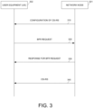
- Figure 3 illustrates a procedure for beam failure recovery (BFR) in accordance with one novel aspect.
- the network node 301 transmits a configuration of at least one channel state information-reference signal (CSI-RS) to the UE 302.
- the configuration of the at least one CSI-RS indicates that the at least one CSI-RS is quasi co-located with reference signals in a serving transmission configuration indication (TCI) .
- TCI serving transmission configuration indication
- step 320 the UE 302 transmits a beam failure recovery (BFR) request to the network node 301 in an event that a BFR is triggered.
- BFR beam failure recovery
- step 330 the network node 301 transmits a response for the BFR request to the UE 302.
- the UE 302 receives the at least one CSI-RS by using antenna port quasi-co-location (QCL) parameters the same as the antenna port QCL parameters associated with a new beam reference signal (RS) from the network node 301.
- QCL antenna port quasi-co-location
- FIG 4 is a flow chart of a method for beam failure recovery (BFR) in accordance with one novel aspect.
- the UE 102 receives a configuration of at least one channel state information-reference signal (CSI-RS) from the network node 101.
- the configuration of the at least one CSI-RS indicates that the at least one CSI-RS is quasi co-located with reference signals in a serving transmission configuration indication (TCI).
- TCI serving transmission configuration indication
- step 402 the UE 102 transmits a beam failure recovery (BFR) request to the network node 101 in an event that a BFR is triggered.
- BFR beam failure recovery
- step 403 the UE 102 receives a response for the BFR request from the network node 101.
- the UE 102 receives the at least one CSI-RS by using antenna port quasi-co-location (QCL) parameters the same as the antenna port QCL parameters associated with a new beam reference signal (RS) from the network node.
- QCL antenna port quasi-co-location
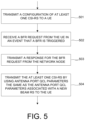
- FIG. 5 is a flow chart of a method for beam failure recovery (BFR) in accordance with another novel aspect.
- the network node 101 transmits a configuration of at least one channel state information-reference signal (CSI-RS) to the UE 102.
- CSI-RS channel state information-reference signal
- the configuration of the at least one CSI-RS indicates that the at least one CSI-RS is quasi co-located with reference signals in a serving transmission configuration indication (TCI) .
- TCI serving transmission configuration indication
- the network node 101 receives a beam failure recovery (BFR) request from the UE in an event that a BFR is triggered.
- BFR beam failure recovery
- step 503 the network node 101 transmits a response for the BFR request to the UE 102.
- the network node 101 transmits the at least one CSI-RS by using antenna port quasi-co-location (QCL) parameters the same as the antenna port QCL parameters associated with a new beam reference signal (RS) to the UE.
- QCL antenna port quasi-co-location
Landscapes
- Engineering & Computer Science (AREA)
- Signal Processing (AREA)
- Computer Networks & Wireless Communication (AREA)
- Mobile Radio Communication Systems (AREA)
Abstract
Description
- This application claims priority under 35 U.S.C. §119 from
U.S. Provisional Application Number 63/272,348, entitled "BFR for Joint and Separate TCI Modes", filed on October 27, 2021 U.S. Provisional Application Number 63/274,034, entitled "BFR for Joint and Separate TCI Modes", filed on November 01, 2021 - The disclosed embodiments relate generally to wireless communication, and, more particularly, to channel state information-reference signal (CSI-RS) associated with serving transmission configuration indication (TCI) in mobile communications.
- The wireless communications network has grown exponentially over the years. A long-term evolution (LTE) system offers high peak data rates, low latency, improved system capacity, and low operating cost resulting from simplified network architecture. LTE systems, also known as the 4G system, also provide seamless integration to older wireless network, such as GSM, CDMA and universal mobile telecommunication system (UMTS). In LTE systems, an evolved universal terrestrial radio access network (E-UTRAN) includes a plurality of evolved Node-Bs (eNodeBs or eNBs) communicating with a plurality of mobile stations, referred to as user equipments (UEs). The 3rd generation partner project (3GPP) network normally includes a hybrid of 2G/3G/4G systems. The next generation mobile network (NGMN) board, has decided to focus the future NGMN activities on defining the end-to-end requirements for 5G new radio (NR) systems.
- In conventional 5G technology, beam failure recovery (BFR) procedure is proposed to handle beam tracking issues, e.g., feedback rate for determined channel state may not be frequent enough or sudden blockage results in lost connection. Furthermore, in conventional 5G technology, the serving transmission configuration indication (TCI) is applied to at least UE-dedicated physical downlink control channel (PDCCH) reception and UE-dedicated physical downlink shared channel (PDSCH) reception.
- After UE receives a response for the BFR request from the network node, the operations of UE associated with a new beam may be worthy of further discussion.
- Apparatus and method for beam failure recovery (BFR) are proposed. In the proposed methods, the network node may allocate channel state information (CSI) configuration for the user equipment (UE). The CSI configuration may comprise at least one CSI-reference signal (CSI-RS) associated with a serving transmission configuration indication (TCI) for the UE. In addition, the network node may transmit the CSI configuration to the UE. The UE may perform BFD procedure to determine whether a beam failure happens and transmit a beam failure recovery (BFR) request to the network node when the beam failure happens. In addition, the UE may perform operations based on the CSI-RS associated with the serving TCI when the UE receives a response from the network node for the BFR request. Methods and a UE according to the invention are defined in the independent claims. The dependent claims define preferred embodiments thereof.
- In one embodiment, a user equipment (UE) receives a configuration of at least one channel state information-reference signal (CSI-RS). The UE transmits a beam failure recovery (BFR) request to the network node in an event that a BFR is triggered. The UE receives a response for the BFR request from the network node. In addition, the UE receives the at least one CSI-RS by using antenna port quasi-co-location (QCL) parameters the same as the antenna port QCL parameters associated with a new beam reference signal (RS) from the network node. The configuration of the at least one CSI-RS may indicate that the at least one CSI-RS is quasi co-located with reference signals in a serving transmission configuration indication (TCI).
- In another embodiment, a network node transmits a configuration of at least one channel state information-reference signal (CSI-RS) to a user equipment (UE). The network node receives a beam failure recovery (BFR) request from the UE in an event that a BFR is triggered. Then, the network node transmits a response for the BFR request to the UE. In addition, the network node transmits the at least one CSI-RS by using antenna port quasi-co-location (QCL) parameters the same as the antenna port QCL parameters associated with a new beam reference signal (RS) to the UE. The configuration of the at least one CSI-RS may indicate that the at least one CSI-RS is quasi co-located with reference signals in a serving transmission configuration indication (TCI).
- Other embodiments and advantages are described in the detailed description below. This summary does not purport to define the invention. The invention is defined by the claims.
- The accompanying drawings, where like numerals indicate like components, illustrate embodiments of the invention.
-
Figure 1 illustrates an exemplary 5G new radio (NR)network 100 in accordance with aspects of the current invention. -
Figure 2 is a simplified block diagram of a network node and a user equipment that carry out certain embodiments of the present invention. -
Figure 3 illustrates a procedure for beam failure recovery (BFR) in accordance with one novel aspect. -
Figure 4 is a flow chart of a method for beam failure recovery (BFR) in accordance with one novel aspect. -
Figure 5 is a flow chart of a method for beam failure recovery (BFR) in accordance with another novel aspect. - Reference will now be made in detail to some embodiments of the invention, examples of which are illustrated in the accompanying drawings.
-
Figure 1 illustrates an exemplary 5G new radio (NR)network 100 in accordance with aspects of the current invention. The5G NR network 100 comprises anetwork node 101 communicatively connected to a user equipment (UE) 102 operating in a licensed band (e.g., 30GHz~300GHz for mmWave) of anaccess network 110 which provides radio access using a Radio Access Technology (RAT) (e.g., the 5G NR technology). Theaccess network 110 is connected to a5G core network 120 by means of the NG interface, more specifically to a User Plane Function (UPF) by means of the NG user-plane part (NG-u), and to a Mobility Management Function (AMF) by means of the NG control-plane part (NG-c). One gNB can be connected to multiple UPFs/AMFs for the purpose of load sharing and redundancy. Thenetwork node 101 may be a gNB. The UE 102 may be a smart phone, a wearable device, an Internet of Things (IoT) device, and a tablet, etc. Alternatively, UE 110 may be a Notebook (NB) or Personal Computer (PC) inserted or installed with a data card which includes a modem and RF transceiver(s) to provide the functionality of wireless communication. - The
network node 101 may provide communication coverage for a geographic coverage area in which communications with the UE 102 is supported via acommunication link 103. Thecommunication link 103 between thenetwork node 101 and the UE 102 may utilize one or more frequency carriers to form one or more cells (e.g., a PCell and one or more Scells). Thecommunication link 103 shown in the5G NR network 100 may include uplink transmissions from the UE 102 to the network node 101 (e.g., on the Physical Uplink Control Channel (PUCCH) or Physical Uplink Shared Channel (PUSCH)) or downlink transmissions from thenetwork node 101 to the UE 102 (e.g., on the Physical Downlink Control Channel (PDCCH) or Physical Downlink Shared Channel (PDSCH)). - In accordance with one novel aspect, the UE 102 may receive a configuration of at least one channel state information-reference signal (CSI-RS) the
network node 101. The configuration of at least one CSI-RS indicates that the at least one CSI-RS is quasi co-located with reference signals in a serving transmission configuration indication (TCI). In an example, the UE 102 may receive the configuration of the CSI-RS associated with the serving TCI through a radio resource control (RRC) signaling. - The serving TCI is used for a physical downlink control channel (PDCCH) reception and a physical downlink shared channel (PDSCH) reception. In accordance with one novel aspect, the CSI-RS associated with the serving TCI is configured to the UE 102 to share the same port quasi-co-location (QCL) parameters as the UE-dedicated PDCCH reception and the PDSCH reception. In addition, the CSI-RS associated with the serving TCI does not comprise QCL information. That is to say, the CSI-RS associated with the serving TCI may be a specific CSI-RS which is configured to share the same QCL parameters as the PDCCH reception and the PDSCH reception, but the CSI-RS associated with the serving TCI does not provide any information of other QCL parameters.
- The UE 102 may perform BFD procedure to determine whether a beam failure happens. When the beam failure happens, the
UE 102 may trigger the bean failure recovery (BFR) procedure. When a BFR procedure is triggered, the UE 102 may transmit a beam failure recovery (BFR) request to thenetwork node 101. The BFR request may comprise at least one of a physical random access channel (PRACH) transmission, physical uplink control channel (PUCCH) transmission with scheduling request (SR) and a BFR medium access control-control element (MAC-CE) which is transmitted on a first physical uplink shared channel (PUSCH). - The
network node 101 may transmit a response for the BFR request from theUE 102. The response may comprise at least one of a downlink control information (DCI) with cyclic redundancy check (CRC) scrambled by cell-radio network temporary identifier (C-RNTI) or modulation coding scheme-cell-RNTI (MCS-C-RNTI) transmitted on PDCCH in a specific search space set, and a DCI scheduling a second PUSCH with the same hybrid automatic repeat request (HARQ) process number as for the first PUSCH and having a toggled new data indicator (NDI) field value. - In accordance with one novel aspect, after the
UE 102 receives the response for the BFR request from thenetwork node 101, theUE 102 may receive the CSI-RS associated with the serving TCI by using the antenna QCL parameters the same as the antenna port QCL parameters associated with a new beam reference signal (RS). The new beam RS may be identified or selected by theUE 102 from a set of candidate beam RSs during the new beam identification (NBI) procedure of the BFR procedure. - In accordance with one novel aspect, the
UE 102 may further receive a sounding reference signal (SRS) configured by thenetwork node 101. The SRS is configured by thenetwork node 101 to use a same spatial domain filter associated with the serving TCI. The SRS is configured to share the same uplink spatial filter as physical uplink control channel (PUSCH) transmission and physical uplink control channel (PUCCH) resources. TheUE 102 may transmit the SRS by using a spatial domain filter which is the same as the spatial domain filter associated with the new beam RS. - In accordance with one novel aspect, the
UE 102 may further receive a configuration of a set of cells for common TCI-State update from thenetwork node 101. Therefore, the configuration of the CSI-RS associated with the serving TCI may be configured in the set of configured cells. That is to say, the CSI-RS associated with the serving TCI is configured to share the same QCL parameters as the PDCCH reception and the PDSCH reception in the set of configured cells. After theUE 102 receives the response for the BFR request from thenetwork node 101, theUE 102 may receive the CSI-RS (associated with the serving TCI) by using the antenna QCL parameters the same as the antenna port QCL parameters associated with a new beam RS in the set of configured cells. In an example, the set of configured cells may be configured in the same band. -
Figure 2 is a simplified block diagram of a network node and a user equipment (UE) that carry out certain embodiments of the present invention. Thenetwork node 201 may be a base station (BS) or a gNB, but the present invention should not be limited thereto. TheUE 202 may be a smart phone, a wearable device, an Internet of Things (IoT) device, and a tablet, etc. Alternatively,UE 202 may be a Notebook (NB) or Personal Computer (PC) inserted or installed with a data card which includes a modem and RF transceiver(s) to provide the functionality of wireless communication. -
Network node 201 has anantenna array 211 having multiple antenna elements that transmits and receives radio signals, one or moreRF transceiver modules 212, coupled with theantenna array 211, receives RF signals fromantenna array 211, converts them to baseband signal, and sends them toprocessor 213.RF transceiver 212 also converts received baseband signals fromprocessor 213, converts them to RF signals, and sends out toantenna array 211.Processor 213 processes the received baseband signals and invokes differentfunctional modules 220 to perform features innetwork node 201.Memory 214 stores program instructions anddata 215 to control the operations ofnetwork node 201.Network node 201 also includes multiple function modules that carry out different tasks in accordance with embodiments of the current invention. - Similarly,
UE 202 has anantenna array 231, which transmits and receives radio signals. ARF transceiver 232, coupled with the antenna, receives RF signals fromantenna array 231, converts them to baseband signals and sends them toprocessor 233.RF transceiver 232 also converts received baseband signals fromprocessor 233, converts them to RF signals, and sends out toantenna array 231.Processor 233 processes the received baseband signals and invokes differentfunctional modules 240 to perform features inUE 202.Memory 234 stores program instructions anddata 235 to control the operations ofUE 202.UE 202 also includes multiple function modules and circuits that carry out different tasks in accordance with embodiments of the current invention. - The functional modules and
circuits circuits processors 213 and 233 (e.g., via executingprogram codes 215 and 235), allownetwork node 201 andUE 202 to perform embodiments of the present invention. - In the example of
Figure 1 , thenetwork node 201 may comprise anallocation circuit 221 and aconfiguration circuit 222. Allocation circuit 121 may allocate CSI configuration for theUE 202. The CSI configuration may comprise at least one CSI-RS associated with a serving transmission configuration indication (TCI) for theUE 202.Configuration circuit 222 may transmit the CSI configuration to theUE 202. - In the example of
Figure 1 , theUE 202 may comprise a beam failure detection (BFD)circuit 241, areport circuit 242 and a determiningcircuit 243.BFD circuit 241 may perform BFD procedure to determine whether a beam failure happens.Report circuit 242 may transmit a beam failure recovery (BFR) request to the network node when theBFD circuit 241 determines that a beam failure happens. Determiningcircuit 243 may perform operations based on the CSI-RS associated with the serving TCI when theUE 202 receive a response for the BFR request from thenetwork node 201. -
Figure 3 illustrates a procedure for beam failure recovery (BFR) in accordance with one novel aspect. Initially, instep 310, thenetwork node 301 transmits a configuration of at least one channel state information-reference signal (CSI-RS) to theUE 302. In an example, the configuration of the at least one CSI-RS indicates that the at least one CSI-RS is quasi co-located with reference signals in a serving transmission configuration indication (TCI) . - In
step 320, theUE 302 transmits a beam failure recovery (BFR) request to thenetwork node 301 in an event that a BFR is triggered. - In
step 330, thenetwork node 301 transmits a response for the BFR request to theUE 302. - In
step 340, theUE 302 receives the at least one CSI-RS by using antenna port quasi-co-location (QCL) parameters the same as the antenna port QCL parameters associated with a new beam reference signal (RS) from thenetwork node 301. -
Figure 4 is a flow chart of a method for beam failure recovery (BFR) in accordance with one novel aspect. Instep 401, theUE 102 receives a configuration of at least one channel state information-reference signal (CSI-RS) from thenetwork node 101. In an example, the configuration of the at least one CSI-RS indicates that the at least one CSI-RS is quasi co-located with reference signals in a serving transmission configuration indication (TCI). - In
step 402, theUE 102 transmits a beam failure recovery (BFR) request to thenetwork node 101 in an event that a BFR is triggered. - In
step 403, theUE 102 receives a response for the BFR request from thenetwork node 101. - In
step 404, theUE 102 receives the at least one CSI-RS by using antenna port quasi-co-location (QCL) parameters the same as the antenna port QCL parameters associated with a new beam reference signal (RS) from the network node. -
Figure 5 is a flow chart of a method for beam failure recovery (BFR) in accordance with another novel aspect. Instep 501, thenetwork node 101 transmits a configuration of at least one channel state information-reference signal (CSI-RS) to theUE 102. In an example, the configuration of the at least one CSI-RS indicates that the at least one CSI-RS is quasi co-located with reference signals in a serving transmission configuration indication (TCI) . - In
step 502, thenetwork node 101 receives a beam failure recovery (BFR) request from the UE in an event that a BFR is triggered. - In
step 503, thenetwork node 101 transmits a response for the BFR request to theUE 102. - In
step 504, thenetwork node 101 transmits the at least one CSI-RS by using antenna port quasi-co-location (QCL) parameters the same as the antenna port QCL parameters associated with a new beam reference signal (RS) to the UE. - Although the present invention has been described in connection with certain specific embodiments for instructional purposes, the present invention is not limited thereto. Accordingly, various modifications, adaptations, and combinations of various features of the described embodiments can be practiced without departing from the scope of the invention as set forth in the claims.
Claims (15)
- A method, comprising:receiving, by a user equipment, in the following also referred to as UE, a configuration of at least one channel state information-reference signal, in the following also referred to as CSI-RS, from a network node (310; 401);transmitting, by the UE, a beam failure recovery, in the following also referred to as BFR, request to the network node in an event that a BFR is triggered (320; 402);receiving, by the UE, a response for the BFR request from the network node (330; 403); andreceiving, by the UE, the at least one CSI-RS by using antenna port quasi-co-location, in the following also referred to as QCL, parameters the same as the antenna port QCL parameters associated with a new beam reference signal, in the following also referred to as RS, from the network node (340; 404).
- The method of Claim 1, wherein the configuration of the at least one CSI-RS is received through a radio resource control, in the following also referred to as RRC, signaling.
- The method of Claim 1 or 2, wherein the configuration of the at least one CSI-RS indicates that the at least one CSI-RS is quasi co-located with reference signals in a serving transmission configuration indication, in the following also referred to as TCI.
- The method of Claim 3, wherein the serving TCI is used for a physical downlink control channel, in the following also referred to as PDCCH, reception and a physical downlink shared channel, in the following also referred to as PDSCH, reception.
- The method of any one of Claims 1 to 4, wherein the new beam RS is identified by the UE from a set of candidate beam RSs.
- The method of any one of Claims 1 to 5, wherein the configuration of the at least one CSI-RS does not comprise QCL information.
- The method of any one of Claims 1 to 6, further comprising:
transmitting, by the UE, a sounding reference signal, in the following also referred to as SRS, by using a spatial domain filter which is the same as the spatial domain filter associated with the new beam RS to the network node, wherein the SRS is configured by the network node to use a same spatial domain filter associated with a serving TCI. - A method, comprising:transmitting, by a network node, a configuration of at least one channel state information-reference signal, in the following also referred to as CSI-RS, to a user equipment, in the following also referred to as UE, (310; 501);receiving, by the network node, a beam failure recovery, in the following also referred to as BFR, request from the UE in an event that a BFR is triggered (320; 502);transmitting, by the network node, a response for the BFR request to the UE (330; 503); andtransmitting, by the network node, the at least one CSI-RS by using antenna port quasi-co-location, in the following also referred to as QCL, parameters the same as the antenna port QCL parameters associated with a new beam reference signal, in the following also referred to as RS, to the UE (340; 504).
- The method of Claim 8, wherein the configuration of the at least one CSI-RS is transmitted through a radio resource control, in the following also referred to as RRC, signaling; and/orwherein the configuration of the at least one CSI-RS indicates that the at least one CSI-RS is quasi co-located with reference signals in a serving transmission configuration indication, in the following also referred to as TCI,wherein preferably the serving TCI is used for a physical downlink control channel, in the following also referred to as PDCCH, reception and a physical downlink shared channel, in the following also referred to as PDSCH, reception.
- The method of Claim 8 or 9, wherein the at least one CSI-RS does not comprise QCL information.
- The method of any one of Claims 8 to 10, further comprising:
receiving, by the network node, a sounding reference signal, in the following also referred to as SRS, by using a spatial domain filter which is the same as the spatial domain filter associated with the new beam RS from the UE, wherein the SRS is configured by the network node to use a same spatial domain filter associated with a serving TCI. - A user equipment, in the following also referred to as UE, (202), comprising:a receiver (232), receiving a configuration of at least one channel state information-reference signal, in the following also referred to as CSI-RS, from a network node and receiving a response for a beam failure recovery, in the following also referred to as BFR, request from the network node; anda transmitter (232), transmitting the BFR request to the network node in an event that a BFR is triggered;wherein the receiver (232) receives the at least one CSI-RS by using antenna port quasi-co-location, in the following also referred to as QCL, parameters the same as the antenna port QCL parameters associated with a new beam reference signal, in the following also referred to as RS, from the network node.
- The UE (202) of Claim 12, wherein the receiver (232) receives the configuration of the at least one CSI-RS through a radio resource control, in the following also referred to as RRC, signaling; and/orwherein the configuration of the at least one CSI-RS indicates that the at least one CSI-RS is quasi co-located with reference signals in a serving transmission configuration indication, in the following also referred to as TCI,wherein preferably the serving TCI is used for a physical downlink control channel, in the following also referred to as PDCCH, reception and a physical downlink shared channel, in the following also referred to as PDSCH, reception; and/orwherein the configuration of the at least one CSI-RS does not comprise QCL information.
- The UE of Claim 12 or 13, further comprises:
a processor, identifying the new beam RS from a set of candidate beam RSs. - The UE of any one of Claims 12 to 14, wherein the transmitter further transmits a sounding reference signal, in the following also referred to as SRS, by using a spatial domain filter which is the same as the spatial domain filter associated with the new beam RS to the network node, wherein the SRS is configured by the network node to use a same spatial domain filter associated with a serving TCI.
Applications Claiming Priority (3)
| Application Number | Priority Date | Filing Date | Title |
|---|---|---|---|
| US202163272348P | 2021-10-27 | 2021-10-27 | |
| US202163274034P | 2021-11-01 | 2021-11-01 | |
| US17/958,426 US20230131462A1 (en) | 2021-10-27 | 2022-10-02 | Apparatus and method for beam failure recovery in mobile communications |
Publications (1)
| Publication Number | Publication Date |
|---|---|
| EP4175192A1 true EP4175192A1 (en) | 2023-05-03 |
Family
ID=83902855
Family Applications (1)
| Application Number | Title | Priority Date | Filing Date |
|---|---|---|---|
| EP22202232.9A Pending EP4175192A1 (en) | 2021-10-27 | 2022-10-18 | Apparatus and method for beam failure recovery in mobile communications |
Country Status (4)
| Country | Link |
|---|---|
| US (1) | US20230131462A1 (en) |
| EP (1) | EP4175192A1 (en) |
| CN (1) | CN116033573A (en) |
| TW (1) | TWI842157B (en) |
Family Cites Families (3)
| Publication number | Priority date | Publication date | Assignee | Title |
|---|---|---|---|---|
| CN118573252A (en) * | 2019-11-25 | 2024-08-30 | 三星电子株式会社 | Method and device for beam fault recovery in network cooperative communication |
| US11764854B2 (en) * | 2019-12-06 | 2023-09-19 | Qualcomm Incorporated | Coordinated beam refinement and coordinated beam failure recovery |
| US12089195B2 (en) * | 2020-04-06 | 2024-09-10 | Samsung Electronics Co., Ltd. | Method and apparatus for uplink reference signal-based beam management |
-
2022
- 2022-10-02 US US17/958,426 patent/US20230131462A1/en not_active Abandoned
- 2022-10-18 EP EP22202232.9A patent/EP4175192A1/en active Pending
- 2022-10-24 CN CN202211307670.9A patent/CN116033573A/en not_active Withdrawn
- 2022-10-26 TW TW111140643A patent/TWI842157B/en active
Non-Patent Citations (2)
| Title |
|---|
| LENOVO ET AL: "Enhancements on Multi-beam Operation", vol. RAN WG1, no. e-Meeting; 20220221 - 20220303, 12 February 2022 (2022-02-12), XP052122254, Retrieved from the Internet <URL:https://ftp.3gpp.org/tsg_ran/WG1_RL1/TSGR1_108-e/Docs/R1-2201426.zip R1-2201426 Multi-beam operation.docx> [retrieved on 20220212] * |
| MODERATOR (SAMSUNG): "Moderator summary for multi-beam enhancement", vol. RAN WG1, no. e-Meeting; 20211011 - 20211019, 12 October 2021 (2021-10-12), XP052060378, Retrieved from the Internet <URL:https://ftp.3gpp.org/tsg_ran/WG1_RL1/TSGR1_106b-e/Inbox/R1-2109466.zip R1-2109466 FeMIMO Item 1 Round 0 - VFinal.docx> [retrieved on 20211012] * |
Also Published As
| Publication number | Publication date |
|---|---|
| CN116033573A (en) | 2023-04-28 |
| TW202318828A (en) | 2023-05-01 |
| TWI842157B (en) | 2024-05-11 |
| US20230131462A1 (en) | 2023-04-27 |
Similar Documents
| Publication | Publication Date | Title |
|---|---|---|
| EP4171165A1 (en) | Secondary cell beam recovery | |
| WO2023109422A1 (en) | Method and appratus for rach procedure with transmission configuration indicatior (tci) state indication | |
| EP3610596B1 (en) | Feedback techniques in wireless communications | |
| US12225565B2 (en) | Methods and apparatus of spatial relation switching in new radio system | |
| US20230262824A1 (en) | Methods and apparatus to speed up direct acell activation | |
| US20230189150A1 (en) | Power saving enhancements with tracking reference signal (trs) in idle mode | |
| US20230096588A1 (en) | Apparatus and method for unknown pucch scell activation | |
| US20160234772A1 (en) | User equipment detection for energy saving cell activation | |
| EP4181417A1 (en) | Method and apparatus for beam group reporting in mobile communications | |
| US12532371B2 (en) | Downlink reception with multiple TCI states | |
| US20230044253A1 (en) | Method and user equipment for beam group reporting in mobile communications | |
| WO2023193623A1 (en) | Method and apparatus for forwarding control information in mobile communications | |
| US20230131462A1 (en) | Apparatus and method for beam failure recovery in mobile communications | |
| US20230171128A1 (en) | Method and apparatus for joint communication and sensing in a mobile communication system | |
| US20230089145A1 (en) | Method and apparatus for new beam identification | |
| US20230090834A1 (en) | Method and apparatus for beam failure recovery procedure | |
| WO2023131344A1 (en) | Method and appratus for relay node configuration and protocol stacks | |
| WO2023131342A1 (en) | Method and appratus for relay node id acquisition | |
| US20250365116A1 (en) | Method and user equipment for performing uplink transmissions to multiple transmission reception points |
Legal Events
| Date | Code | Title | Description |
|---|---|---|---|
| PUAI | Public reference made under article 153(3) epc to a published international application that has entered the european phase |
Free format text: ORIGINAL CODE: 0009012 |
|
| STAA | Information on the status of an ep patent application or granted ep patent |
Free format text: STATUS: THE APPLICATION HAS BEEN PUBLISHED |
|
| AK | Designated contracting states |
Kind code of ref document: A1 Designated state(s): AL AT BE BG CH CY CZ DE DK EE ES FI FR GB GR HR HU IE IS IT LI LT LU LV MC ME MK MT NL NO PL PT RO RS SE SI SK SM TR |
|
| STAA | Information on the status of an ep patent application or granted ep patent |
Free format text: STATUS: REQUEST FOR EXAMINATION WAS MADE |
|
| 17P | Request for examination filed |
Effective date: 20231031 |
|
| RBV | Designated contracting states (corrected) |
Designated state(s): AL AT BE BG CH CY CZ DE DK EE ES FI FR GB GR HR HU IE IS IT LI LT LU LV MC ME MK MT NL NO PL PT RO RS SE SI SK SM TR |
|
| STAA | Information on the status of an ep patent application or granted ep patent |
Free format text: STATUS: EXAMINATION IS IN PROGRESS |
|
| 17Q | First examination report despatched |
Effective date: 20250212 |