EP4175162A1 - Stepping motor abnormality detecting device - Google Patents
Stepping motor abnormality detecting device Download PDFInfo
- Publication number
- EP4175162A1 EP4175162A1 EP21829688.7A EP21829688A EP4175162A1 EP 4175162 A1 EP4175162 A1 EP 4175162A1 EP 21829688 A EP21829688 A EP 21829688A EP 4175162 A1 EP4175162 A1 EP 4175162A1
- Authority
- EP
- European Patent Office
- Prior art keywords
- stepping motor
- current level
- power supply
- detecting device
- abnormality detecting
- Prior art date
- Legal status (The legal status is an assumption and is not a legal conclusion. Google has not performed a legal analysis and makes no representation as to the accuracy of the status listed.)
- Granted
Links
Images



Classifications
-
- H—ELECTRICITY
- H02—GENERATION; CONVERSION OR DISTRIBUTION OF ELECTRIC POWER
- H02P—CONTROL OR REGULATION OF ELECTRIC MOTORS, ELECTRIC GENERATORS OR DYNAMO-ELECTRIC CONVERTERS; CONTROLLING TRANSFORMERS, REACTORS OR CHOKE COILS
- H02P8/00—Arrangements for controlling dynamo-electric motors rotating step by step
- H02P8/36—Protection against faults, e.g. against overheating or step-out; Indicating faults
- H02P8/38—Protection against faults, e.g. against overheating or step-out; Indicating faults the fault being step-out
-
- H—ELECTRICITY
- H02—GENERATION; CONVERSION OR DISTRIBUTION OF ELECTRIC POWER
- H02P—CONTROL OR REGULATION OF ELECTRIC MOTORS, ELECTRIC GENERATORS OR DYNAMO-ELECTRIC CONVERTERS; CONTROLLING TRANSFORMERS, REACTORS OR CHOKE COILS
- H02P8/00—Arrangements for controlling dynamo-electric motors rotating step by step
- H02P8/12—Control or stabilisation of current
Definitions
- the present disclosure relates to a device that detects an abnormality in driving of a stepping motor. More particularly, the present disclosure relates to a device that detects an abnormality of a stepping motor employed in a two-way valve for opening and closing a gas flow in a gas meter.
- PTL 1 discloses a shut-off valve device that determines a stall state or a step-out state of a stepping motor.
- This shut-off valve device includes a drive control circuit that controls driving of the stepping motor and a valve abnormality circuit that determines a stall state or step-out state of the stepping motor. As illustrated in FIG. 4 , the shut-off valve device is capable of determining the stall state or step-out state by comparing a maximum value or a wave height of the maximum value in a drive voltage waveform detected from the stepping motor with a predetermined threshold.
- FIG. 4 is a graph illustrating a current level change while the stepping motor is driven.
- PTL2 discloses a step-out detection method for stepping motors.
- a motor current waveform in a stepping motor driver that drives the stepping motor is converted into a rectangular wave signal, and this rectangular wave signal is converted into a voltage signal. Then, a voltage value acquired from the voltage signal is compared with a reference voltage to determine occurrence of the step-out state.
- Both PTL1 and PTL2 disclose techniques focused on a difference in current and voltage waveforms between the normal and step-out states. These techniques are capable of detecting a waveform difference in a stable step-out state. However, in a practical operating environment, the stepping motor often repeats unstable behavior such as slight rotation or return. In such case, the waveform difference becomes unclear and it becomes difficult to distinguish between the normal and step-out states.
- the present disclosure provides a stepping motor abnormality detecting device that is capable of correcting a waveform detected in an unstable state to reliably detect an abnormality of the stepping motor.
- the stepping motor abnormality detecting device of the present disclosure includes an instantaneous current detector, an integrator, and a determiner.
- the instantaneous current detector acquires a reference current of the stepping motor.
- the integrator generates an average drive current.
- the determiner compares the average drive current with a predetermined threshold based on the reference current, and determines the abnormality of the stepping motor.
- the present disclosure provides the stepping motor abnormality detecting device capable of detecting the abnormality of the stepping motor even in the unstable operating environment.
- the first exemplary embodiment will be described below with referent to FIG. 1 to FIG. 5 .
- FIG. 1 is a block diagram of an example of a configuration of stepping motor abnormality detecting device 100 according to the first exemplary embodiment.
- stepping motor 4 is connected to stepping motor driver 3.
- Stepping motor driver 3 is connected to power supply 1 via current level detector 2.
- Current level detector 2 is also connected to determiner 5.
- Determiner 5 and stepping motor driver 3 are connected to controller 6 and controlled by controller 6.
- Power supply 1 is configured by connecting a plurality of primary lithium batteries (not illustrated) in parallel. Power supply 1 has a battery capacity equivalent to a current capacity consumed by an electrical system within a validity period of verification.
- the validity period is, for example, 15 years.
- Current level detector 2 has instantaneous current level detector 21 that detects a level of instantaneous current flowing in stepping motor driver 3.
- Current level detector 2 further includes integrator 22 that integrates the current level detected, and power supply impedance estimator 23 that estimates impedance of power supply 1 (hereinafter referred to as power supply impedance).
- Stepping motor driver 3 is controlled by controller 6, and outputs a drive pulse for driving stepping motor 4 to drive stepping motor 4.
- stepping motor 4 When stepping motor 4 is employed in a gas meter, stepping motor 4 is regarded as a valve for controlling a gas flow rate. In this case, stepping motor 4 performs two types of operation: a shut-off operation to shut off gas and a return operation to release the gas shut-off operation.
- Determiner 5 includes corrector 55.
- Corrector 55 uses the power supply impedance acquired by power supply impedance estimator 23 to correct the current level detected by current level detector 2 and integrated by integrator 22.
- determiner 5 includes first comparator 53 and second comparator 54. Each of first comparator 53 and second comparator 54 compares the current level corrected by corrector 55 with a predetermined determination threshold.
- the determination threshold used in first comparator 53 is set by first determination threshold setter 51.
- the determination threshold used in second comparator 54 is set by second determination threshold setter 52.
- Controller 6 controls stepping motor driver 3. Controller 6 performs the shut-off and return operations of the gas meter by operating stepping motor 4 via stepping motor driver 3. Still more, controller 6 retains timing information that specifies timing to detect the current level by current level detector 2. Furthermore, controller 6 stores a determination result acquired by determiner 5.
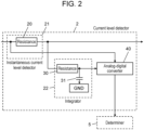
- FIG. 2 is a block diagram illustrating an example of a configuration of current level detector 2 according to the first exemplary embodiment.
- Instantaneous current level detector 21 has resistance 20.
- Integrator 22 integrates the current flowing from resistance 20 to stepping motor driver 3 by resistance 30 and capacitor 31.
- Capacitor 31 is connected to ground (GND).
- Analog-digital converter 40 has a function to convert input current from an analog value to a digital value. More specifically, using an output voltage of power supply 1 as a reference voltage, voltage acquired by integrating current flowing in resistance 20 by integrator 22 is converted into a digital value. Accordingly, the smaller the digital value is, the larger the current is. In the present exemplary embodiment, this digital value is regarded as the current level. The converted digital value is output to determiner 5, and determiner 5 uses this digital value for determination. Analog-digital converter 40 also functions as power supply impedance estimator 23.
- stepping motor abnormality detecting device 100 The operation of stepping motor abnormality detecting device 100 as configured above will be described below.
- instantaneous current level detector 21 acquires a current level while stepping motor 4 is driven.
- corrector 55 corrects the current level using the power supply impedance estimated by power supply impedance estimator 23.
- first comparator 53 and second comparator 54 compare the current level after correction with the predetermined determination thresholds, and determiner 5 determines abnormality of the stepping motor. The operation will be detailed below.
- Current level detector 2 retains the timing information that specifies timing to detect the current level.
- Current level detector 2 acquires the current level at a predetermined timing, based on the timing information, while stepping motor 4 is driven. More specifically, controller 6 controls stepping motor driver 3 to drive stepping motor 4.
- analog-digital converter 40 converts the current level acquired by instantaneous current level detector 21 into a digital value.
- a timing that analog-digital converter 40 acquires the digital value can be arbitrary set. However, the timing is limited to while stepping motor 4 is driven.
- the number of times that analog-digital converter 40 acquires the digital value is not limited to once. For example, analog-digital converter 40 can calculate an average by acquiring the digital value more than once to prevent faulty determination typically due to noise.
- FIG. 4 a current level change is illustrated according to a difference in power supply impedance while stepping motor 4 is driven when stepping motor 4 is employed for driving a shut-off valve.
- FIG. 4 illustrates the current level change in a period when stepping motor driver 3 is turned ON at timing A to change the shut-off vale from a full open state to a full close state by closing the shut-off valve until stepping motor driver 3 is turned OFF at timing B after the rotation of stepping motor 4 is stopped.
- the current level is the digital value as described above.
- FIG. 4 the current level change immediately before timing B indicates that a load has increased due to stopping of the rotation of stepping motor 4. Still more, FIG. 4 indicates that the current level is higher, compared with the current level in the normal state, when the impedance is high. Accordingly, it can be confirmed that the current flow is increased by increased internal impedance of the lithium batteries configuring power supply 1 due to temperature change and decreased battery capacity.
- the current level is acquired by converting instantaneous current flowing in stepping motor driver 3 into voltage, using resistance 20.
- the current level detected is divided by a voltage value of power supply 1 and then the result is multiplied by 1024.
- the current level change from timing B to timing C indicates a state that the current level gradually reaches 1024 by the action of integrator 22 after current consumption of stepping motor 4 becomes 0 at timing B.
- Stepping motor abnormality detecting device 100 acquires the power supply impedance by power supply impedance estimator 23 at a moment between operation ON and OFF. More specifically, the power supply impedance is calculated by acquiring a difference between the upper limit of current level, i.e., 1024, and the current level detected at each timing of operation ON (timing A) and operation OFF (timing B). As illustrated in FIG. 4 , when the power supply impedance is high, the aforementioned difference becomes small at operation ON and large at operation OFF. Corrector 55 corrects the current level according to the power supply impedance acquired by power supply impedance estimator 23.
- analog-digital converter 40 converts the current flowing at the predetermined timing while stepping motor is driven into the current level indicated by the digital value.
- Corrector 55 uses the power supply impedance acquired by power supply impedance estimator 23 to correct the current level acquired by integrator 22 to the current level used for abnormality determination.
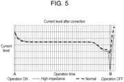
- FIG. 5 is a graph illustrating the current level after correcting the current level illustrated in FIG. 4 by corrector 55.
- an absolute value of the current level is large at operation ON and during the operation of the stepping motor, and an absolute value of the current level is small at operation OFF.
- the current level change due to power supply impedance can be converted in to a constant current level change. This can significantly reduce faulty determination by determiner 5 described later due to variation in power supply impedance. As a result, high precision abnormality detection can be achieved.
- FIG. 3 is a flow chart illustrating an abnormality determining method in determiner 5 according to the first exemplary embodiment.
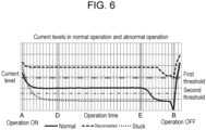
- FIG. 6 is a graph illustrating the current level of stepping motor 4 during the normal operation, the current level of stepping motor during abnormal operation (disconnection), the current level of stepping motor 4 in a step-out or stuck state, a first threshold (first determination threshold), and a second threshold (second determination threshold).
- stepping motor abnormality detecting device 100 first detects current level Z1 corrected at the predetermined timing while the stepping motor is driven (Step S1).
- the predetermined timing is set in a period between point D and point E in FIG. 6 where the current level is stable.
- first comparator 53 compares current level Z1 with the first threshold (Step S2).
- Step S2 when current level Z1 is determined to be greater than the first threshold (Yes in Step S2), determiner 5 determines that stepping motor 4 is disconnected (R1).
- second comparator 54 compares current level Z1 with the second threshold (Step S3).
- Step S3 when current level Z1 is determined to be less than the second threshold (Yes in Step S3), determiner 5 determines that stepping motor 4 is in the step-out or stuck state (R2). When no abnormality is determined through comparison of current level Z1 with the first threshold and the second threshold (No in Step S3), determiner 5 determines that stepping motor 4 is normally operated (R3). Note that processes in Step S2 and Step S3 may be performed in a reverse order in the flow chart illustrated in FIG. 3 .
- stepping motor abnormality detecting device 100 in the first exemplary embodiment includes power supply 1, current level detector 2, stepping motor driver 3, and determiner 5.
- Current level detector 2 detects the instantaneous current level of current flowing from power supply 1 to stepping motor driver 3, and integrates the instantaneous current level detected to estimate the power supply impedance.
- Determiner 5 corrects the integrated value, using the power supply impedance, and compares the corrected value with the predetermined thresholds.
- stepping motor abnormality detecting device 100 is capable of detecting the abnormal operation, such as disconnection and sticking, of the stepping motor at high precision without being affected by the unstable operation of the stepping motor because the current level is corrected according to the power supply impedance.
- the exemplary embodiment refers to the example of operation in which the current level is detected in a period at the stable current level.
- a current level detection timing is not limited to the period at the stable current level.
- stepping motor abnormality detecting device 100 is capable of detecting the abnormality of the stepping motor by setting the first threshold and the second threshold to values that can determine abnormality.
- stepping motor abnormality detecting device 100 may input only the current level of the current flowing in stepping motor driver 3 to analog-digital converter 40 without using instantaneous current level detector 21 and integrator 22.
- the present disclosure is applicable to battery equipment employing a stepping motor, and more particularly to water meters.
Landscapes
- Engineering & Computer Science (AREA)
- Power Engineering (AREA)
- Control Of Stepping Motors (AREA)
Abstract
Description
- The present disclosure relates to a device that detects an abnormality in driving of a stepping motor. More particularly, the present disclosure relates to a device that detects an abnormality of a stepping motor employed in a two-way valve for opening and closing a gas flow in a gas meter.
-
PTL 1 discloses a shut-off valve device that determines a stall state or a step-out state of a stepping motor. - This shut-off valve device includes a drive control circuit that controls driving of the stepping motor and a valve abnormality circuit that determines a stall state or step-out state of the stepping motor. As illustrated in
FIG. 4 , the shut-off valve device is capable of determining the stall state or step-out state by comparing a maximum value or a wave height of the maximum value in a drive voltage waveform detected from the stepping motor with a predetermined threshold.FIG. 4 is a graph illustrating a current level change while the stepping motor is driven. - PTL2 discloses a step-out detection method for stepping motors. In the step-out detection method, a motor current waveform in a stepping motor driver that drives the stepping motor is converted into a rectangular wave signal, and this rectangular wave signal is converted into a voltage signal. Then, a voltage value acquired from the voltage signal is compared with a reference voltage to determine occurrence of the step-out state.
-
- PTL 1: Unexamined
Japanese Patent Publication No. 2006-118642 - PTL 2: Unexamined
Japanese Patent Publication No. 1999-187697 - Both PTL1 and PTL2 disclose techniques focused on a difference in current and voltage waveforms between the normal and step-out states. These techniques are capable of detecting a waveform difference in a stable step-out state. However, in a practical operating environment, the stepping motor often repeats unstable behavior such as slight rotation or return. In such case, the waveform difference becomes unclear and it becomes difficult to distinguish between the normal and step-out states.
- The present disclosure provides a stepping motor abnormality detecting device that is capable of correcting a waveform detected in an unstable state to reliably detect an abnormality of the stepping motor.
- The stepping motor abnormality detecting device of the present disclosure includes an instantaneous current detector, an integrator, and a determiner. The instantaneous current detector acquires a reference current of the stepping motor. The integrator generates an average drive current. The determiner compares the average drive current with a predetermined threshold based on the reference current, and determines the abnormality of the stepping motor.
- The present disclosure provides the stepping motor abnormality detecting device capable of detecting the abnormality of the stepping motor even in the unstable operating environment.
-
-
FIG. 1 is a block diagram illustrating an example of a configuration of a stepping motor abnormality detecting device according to a first exemplary embodiment. -
FIG. 2 is a block diagram illustrating an example of a configuration of a current level detector according to the first exemplary embodiment. -
FIG. 3 is a flow chart illustrating an operation of a determiner according to the first exemplary embodiment. -
FIG. 4 is a graph illustrating a current level change while the stepping motor is driven. -
FIG. 5 is a graph illustrating a current level after correcting the current level by a corrector while the stepping motor is driven according to the first exemplary embodiment. -
FIG. 6 is a graph illustrating a current level during normal operation and a current level during abnormal operation of the stepping motor. - Exemplary embodiments will be detailed below with reference to the drawings. However, detailed description more than necessary may be omitted. For example, details of broadly-known facts or duplicate description of substantially the same structure may be omitted. This is to prevent the following description from becoming redundant more than necessary and facilitate understanding of those skilled in the art.
- The attached drawings and the following description are provided to enable those skilled in the art to sufficiently understand the present disclosure, and do not intend to limit the subject matters in the scope of claims.
- The first exemplary embodiment will be described below with referent to
FIG. 1 to FIG. 5 . -
FIG. 1 is a block diagram of an example of a configuration of stepping motorabnormality detecting device 100 according to the first exemplary embodiment. As illustrated inFIG. 1 , steppingmotor 4 is connected to steppingmotor driver 3. Steppingmotor driver 3 is connected topower supply 1 viacurrent level detector 2.Current level detector 2 is also connected to determiner 5. Determiner 5 and steppingmotor driver 3 are connected to controller 6 and controlled by controller 6. -
Power supply 1 is configured by connecting a plurality of primary lithium batteries (not illustrated) in parallel.Power supply 1 has a battery capacity equivalent to a current capacity consumed by an electrical system within a validity period of verification. The validity period is, for example, 15 years. -
Current level detector 2 has instantaneouscurrent level detector 21 that detects a level of instantaneous current flowing in steppingmotor driver 3.Current level detector 2 further includesintegrator 22 that integrates the current level detected, and powersupply impedance estimator 23 that estimates impedance of power supply 1 (hereinafter referred to as power supply impedance). - Stepping
motor driver 3 is controlled by controller 6, and outputs a drive pulse for driving steppingmotor 4 to drive steppingmotor 4. - When stepping
motor 4 is employed in a gas meter, steppingmotor 4 is regarded as a valve for controlling a gas flow rate. In this case, steppingmotor 4 performs two types of operation: a shut-off operation to shut off gas and a return operation to release the gas shut-off operation. - Determiner 5 includes
corrector 55. Corrector 55 uses the power supply impedance acquired by powersupply impedance estimator 23 to correct the current level detected bycurrent level detector 2 and integrated byintegrator 22. Still more,determiner 5 includesfirst comparator 53 andsecond comparator 54. Each offirst comparator 53 andsecond comparator 54 compares the current level corrected bycorrector 55 with a predetermined determination threshold. The determination threshold used infirst comparator 53 is set by firstdetermination threshold setter 51. The determination threshold used insecond comparator 54 is set by seconddetermination threshold setter 52. - Controller 6 controls stepping
motor driver 3. Controller 6 performs the shut-off and return operations of the gas meter by operatingstepping motor 4 viastepping motor driver 3. Still more, controller 6 retains timing information that specifies timing to detect the current level bycurrent level detector 2. Furthermore, controller 6 stores a determination result acquired bydeterminer 5. -
FIG. 2 is a block diagram illustrating an example of a configuration ofcurrent level detector 2 according to the first exemplary embodiment. - Instantaneous
current level detector 21 hasresistance 20. -
Integrator 22 integrates the current flowing fromresistance 20 to steppingmotor driver 3 byresistance 30 andcapacitor 31.Capacitor 31 is connected to ground (GND). - Analog-
digital converter 40 has a function to convert input current from an analog value to a digital value. More specifically, using an output voltage ofpower supply 1 as a reference voltage, voltage acquired by integrating current flowing inresistance 20 byintegrator 22 is converted into a digital value. Accordingly, the smaller the digital value is, the larger the current is. In the present exemplary embodiment, this digital value is regarded as the current level. The converted digital value is output todeterminer 5, anddeterminer 5 uses this digital value for determination. Analog-digital converter 40 also functions as powersupply impedance estimator 23. - The operation of stepping motor
abnormality detecting device 100 as configured above will be described below. In stepping motorabnormality detecting device 100, instantaneouscurrent level detector 21 acquires a current level while steppingmotor 4 is driven. Then, corrector 55 corrects the current level using the power supply impedance estimated by powersupply impedance estimator 23. Then,first comparator 53 andsecond comparator 54 compare the current level after correction with the predetermined determination thresholds, anddeterminer 5 determines abnormality of the stepping motor. The operation will be detailed below. -
Current level detector 2 retains the timing information that specifies timing to detect the current level.Current level detector 2 acquires the current level at a predetermined timing, based on the timing information, while steppingmotor 4 is driven. More specifically, controller 6 controls steppingmotor driver 3 to drive steppingmotor 4. While steppingmotor 4 is driven, analog-digital converter 40 converts the current level acquired by instantaneouscurrent level detector 21 into a digital value. A timing that analog-digital converter 40 acquires the digital value can be arbitrary set. However, the timing is limited to while steppingmotor 4 is driven. The number of times that analog-digital converter 40 acquires the digital value is not limited to once. For example, analog-digital converter 40 can calculate an average by acquiring the digital value more than once to prevent faulty determination typically due to noise. - In
FIG. 4 , a current level change is illustrated according to a difference in power supply impedance while steppingmotor 4 is driven when steppingmotor 4 is employed for driving a shut-off valve.FIG. 4 illustrates the current level change in a period when steppingmotor driver 3 is turned ON at timing A to change the shut-off vale from a full open state to a full close state by closing the shut-off valve until steppingmotor driver 3 is turned OFF at timing B after the rotation of steppingmotor 4 is stopped. InFIG. 4 , the current level is the digital value as described above. - In
FIG. 4 , the current level change immediately before timing B indicates that a load has increased due to stopping of the rotation of steppingmotor 4. Still more,FIG. 4 indicates that the current level is higher, compared with the current level in the normal state, when the impedance is high. Accordingly, it can be confirmed that the current flow is increased by increased internal impedance of the lithium batteries configuringpower supply 1 due to temperature change and decreased battery capacity. - The current level is acquired by converting instantaneous current flowing in stepping
motor driver 3 into voltage, usingresistance 20. The current level detected is divided by a voltage value ofpower supply 1 and then the result is multiplied by 1024. In other words, when steppingmotor 4 is not operating, the detected current level and the voltage value ofpower supply 1 are equivalent, and thus the calculated current level becomes 1024. InFIG. 4 , the current level change from timing B to timing C indicates a state that the current level gradually reaches 1024 by the action ofintegrator 22 after current consumption of steppingmotor 4 becomes 0 at timing B. - Stepping motor
abnormality detecting device 100 acquires the power supply impedance by powersupply impedance estimator 23 at a moment between operation ON and OFF. More specifically, the power supply impedance is calculated by acquiring a difference between the upper limit of current level, i.e., 1024, and the current level detected at each timing of operation ON (timing A) and operation OFF (timing B). As illustrated inFIG. 4 , when the power supply impedance is high, the aforementioned difference becomes small at operation ON and large at operation OFF.Corrector 55 corrects the current level according to the power supply impedance acquired by powersupply impedance estimator 23. - As described above, in
current level detector 2, analog-digital converter 40 converts the current flowing at the predetermined timing while stepping motor is driven into the current level indicated by the digital value.Corrector 55 uses the power supply impedance acquired by powersupply impedance estimator 23 to correct the current level acquired byintegrator 22 to the current level used for abnormality determination. -
FIG. 5 is a graph illustrating the current level after correcting the current level illustrated inFIG. 4 bycorrector 55. InFIG. 4 , it can be confirmed that an absolute value of the current level is large at operation ON and during the operation of the stepping motor, and an absolute value of the current level is small at operation OFF. By performing correction described above, the current level change due to power supply impedance can be converted in to a constant current level change. This can significantly reduce faulty determination bydeterminer 5 described later due to variation in power supply impedance. As a result, high precision abnormality detection can be achieved. -
FIG. 3 is a flow chart illustrating an abnormality determining method indeterminer 5 according to the first exemplary embodiment. -
FIG. 6 is a graph illustrating the current level of steppingmotor 4 during the normal operation, the current level of stepping motor during abnormal operation (disconnection), the current level of steppingmotor 4 in a step-out or stuck state, a first threshold (first determination threshold), and a second threshold (second determination threshold). - As illustrated in
FIG. 3 , stepping motorabnormality detecting device 100 first detects current level Z1 corrected at the predetermined timing while the stepping motor is driven (Step S1). In the present exemplary embodiment, the predetermined timing is set in a period between point D and point E inFIG. 6 where the current level is stable. Next,first comparator 53 compares current level Z1 with the first threshold (Step S2). In Step S2, when current level Z1 is determined to be greater than the first threshold (Yes in Step S2),determiner 5 determines that steppingmotor 4 is disconnected (R1). On the other hand, when current level Z1 is determined to be equal to or lower than the first threshold in Step S2 (No in Step S2),second comparator 54 compares current level Z1 with the second threshold (Step S3). In Step S3, when current level Z1 is determined to be less than the second threshold (Yes in Step S3),determiner 5 determines that steppingmotor 4 is in the step-out or stuck state (R2). When no abnormality is determined through comparison of current level Z1 with the first threshold and the second threshold (No in Step S3),determiner 5 determines that steppingmotor 4 is normally operated (R3). Note that processes in Step S2 and Step S3 may be performed in a reverse order in the flow chart illustrated inFIG. 3 . - As described above, stepping motor
abnormality detecting device 100 in the first exemplary embodiment includespower supply 1,current level detector 2, steppingmotor driver 3, anddeterminer 5.Current level detector 2 detects the instantaneous current level of current flowing frompower supply 1 to steppingmotor driver 3, and integrates the instantaneous current level detected to estimate the power supply impedance.Determiner 5 corrects the integrated value, using the power supply impedance, and compares the corrected value with the predetermined thresholds. - Accordingly, even during the unstable operation, stepping motor
abnormality detecting device 100 is capable of detecting the abnormal operation, such as disconnection and sticking, of the stepping motor at high precision without being affected by the unstable operation of the stepping motor because the current level is corrected according to the power supply impedance. - The exemplary embodiment refers to the example of operation in which the current level is detected in a period at the stable current level. However, a current level detection timing is not limited to the period at the stable current level. Even in a period that the current level changes, stepping motor
abnormality detecting device 100 is capable of detecting the abnormality of the stepping motor by setting the first threshold and the second threshold to values that can determine abnormality. - In the exemplary embodiment, stepping motor
abnormality detecting device 100 may input only the current level of the current flowing in steppingmotor driver 3 to analog-digital converter 40 without using instantaneouscurrent level detector 21 andintegrator 22. - Note that the above exemplary embodiments are merely examples of the technique of the present disclosure, and all changes, replacements, additions, omissions, and the like which come within the range of equivalency of the claims are therefore intended to be embraced therein.
- The present disclosure is applicable to battery equipment employing a stepping motor, and more particularly to water meters.
-
- 1: power supply
- 2 2: current level detector
- 3: stepping motor driver
- 4: stepping motor
- 5: determiner
- 6: controller
- 20: resistance
- 30: resistance
- 31: capacitor
- 40: analog-digital converter
- 100: stepping motor abnormality detecting device
Claims (9)
- A stepping motor abnormality detecting device comprising:a stepping motor driver configured to output a drive pulse for driving a stepping motor;a power supply configured to supply power to the stepping motor driver;a current level detector configured to detect current flowing in the stepping motor driver; anda determiner configured to determine whether or not the stepping motor is in a normal operation state by comparing a current level detected by the current level detector with a determination threshold predetermined based on a current level when the stepping motor operates normally.
- The stepping motor abnormality detecting device of claim 1, wherein
the determiner has a first determination threshold as the determination threshold, the first determination threshold being used for determining a disconnected state of the stepping motor. - The stepping motor abnormality detecting device of claim 1, wherein
the determiner has a second determination threshold as the determination threshold, the second determination threshold being used for determining a stuck state of the stepping motor. - The stepping motor abnormality detecting device of one of claims 1 to 3, wherein
the current level detector is configured with an integrator that integrates an instantaneous current. - The stepping motor abnormality detecting device of claim 4, whereinthe current level detector is configured by inserting resistance between the power supply and the stepping motor driver, andthe integrator is configured to integrate a signal at a connection point of the resistance and the stepping motor driver by a capacitor via the resistance.
- The stepping motor abnormality detecting device of one of claims 1 to 5, wherein
the current level detector includes an analog-digital converter that converts the current level into a digital signal corresponding to the current level. - The stepping motor abnormality detecting device of one of claims 1 to 6, wherein
the current level detector includes a power supply impedance estimator that estimates power supply impedance of the power supply, and the determination threshold or the current level is corrected based on the power supply impedance estimated. - The stepping motor abnormality detecting device of claim 7, wherein
the power supply impedance estimator estimates larger power supply impedance as an output voltage difference of the power supply increases between operation ON and operation OFF of the stepping motor driver. - The stepping motor abnormality detecting device of claim 8, wherein
the output voltage difference of the power supply between the operation ON and the operation OFF of the stepping motor driver is a ratio of an output voltage of the power supply to an output from the integrator after the stepping motor driver changes from the operation ON to the operation OFF.
Applications Claiming Priority (2)
| Application Number | Priority Date | Filing Date | Title |
|---|---|---|---|
| JP2020109221A JP7390621B2 (en) | 2020-06-25 | 2020-06-25 | Stepping motor abnormality detection device |
| PCT/JP2021/023143 WO2021261387A1 (en) | 2020-06-25 | 2021-06-18 | Stepping motor abnormality detecting device |
Publications (3)
| Publication Number | Publication Date |
|---|---|
| EP4175162A1 true EP4175162A1 (en) | 2023-05-03 |
| EP4175162A4 EP4175162A4 (en) | 2023-11-29 |
| EP4175162B1 EP4175162B1 (en) | 2025-08-13 |
Family
ID=79281272
Family Applications (1)
| Application Number | Title | Priority Date | Filing Date |
|---|---|---|---|
| EP21829688.7A Active EP4175162B1 (en) | 2020-06-25 | 2021-06-18 | Stepping motor abnormality detecting device |
Country Status (8)
| Country | Link |
|---|---|
| US (1) | US12132436B2 (en) |
| EP (1) | EP4175162B1 (en) |
| JP (1) | JP7390621B2 (en) |
| CN (1) | CN115836473B (en) |
| ES (1) | ES3047719T3 (en) |
| PL (1) | PL4175162T3 (en) |
| PT (1) | PT4175162T (en) |
| WO (1) | WO2021261387A1 (en) |
Family Cites Families (17)
| Publication number | Priority date | Publication date | Assignee | Title |
|---|---|---|---|---|
| JP2545641B2 (en) * | 1990-08-09 | 1996-10-23 | 本田技研工業株式会社 | Drive controller for pulse motor |
| JPH0799796A (en) * | 1993-09-27 | 1995-04-11 | Fujitsu Ten Ltd | Driving device for stepping motor |
| KR100316280B1 (en) * | 1995-03-10 | 2002-04-24 | 무라타 기카이 가부시키가이샤 | Step motor control method |
| JPH08275592A (en) | 1995-03-30 | 1996-10-18 | Canon Inc | Motor control circuit |
| JP4054426B2 (en) | 1997-12-18 | 2008-02-27 | 日本パルスモーター株式会社 | Stepping motor step-out detection method |
| US6476578B2 (en) * | 1999-12-01 | 2002-11-05 | Canon Kabushiki Kaisha | Stepping motor driving apparatus and image forming apparatus having such driving apparatus |
| JP3461313B2 (en) * | 1999-12-02 | 2003-10-27 | キヤノン株式会社 | Image forming apparatus with stepping motor out-of-step detection device |
| JP4257603B2 (en) * | 2004-07-09 | 2009-04-22 | サンケン電気株式会社 | Disconnection detection device for stepping motor drive device |
| JP2006118642A (en) | 2004-10-22 | 2006-05-11 | Tokyo Gas Co Ltd | Shut-off valve device |
| JP5382566B2 (en) * | 2008-03-21 | 2014-01-08 | 株式会社ダイヘン | Impedance matching device |
| WO2012102232A1 (en) * | 2011-01-25 | 2012-08-02 | ローム株式会社 | Drive circuit for stepping motor, integrated circuit for same and electronic device comprising same, and control method for stepping motor drive circuit |
| JP4948685B1 (en) * | 2011-08-10 | 2012-06-06 | 三菱電機株式会社 | Position detector, drive control device, and motor drive control system |
| CN103124159A (en) * | 2013-01-24 | 2013-05-29 | 珠海市蓝德节能科技有限公司 | Alternating current dynamo electricity saving control method and dynamo electricity saving device implementing method |
| US9318944B2 (en) * | 2013-04-29 | 2016-04-19 | Rockwell Automation Technologies, Inc. | Methods and apparatus for active front end filter capacitor degradation detection |
| JP6271925B2 (en) * | 2013-09-17 | 2018-01-31 | Necプラットフォームズ株式会社 | Stepping motor failure detection circuit, stepping motor drive device, and stepping motor drive system |
| CN106150728B (en) | 2015-03-31 | 2019-09-20 | 长城汽车股份有限公司 | Fault Detection and Treatment Method of Continuously Variable Valve Lift Mechanism |
| JP6548619B2 (en) * | 2016-08-31 | 2019-07-24 | ミネベアミツミ株式会社 | Motor control device and method for detecting out-of-step condition |
-
2020
- 2020-06-25 JP JP2020109221A patent/JP7390621B2/en active Active
-
2021
- 2021-06-18 ES ES21829688T patent/ES3047719T3/en active Active
- 2021-06-18 PL PL21829688.7T patent/PL4175162T3/en unknown
- 2021-06-18 EP EP21829688.7A patent/EP4175162B1/en active Active
- 2021-06-18 WO PCT/JP2021/023143 patent/WO2021261387A1/en not_active Ceased
- 2021-06-18 CN CN202180043934.1A patent/CN115836473B/en active Active
- 2021-06-18 US US17/997,735 patent/US12132436B2/en active Active
- 2021-06-18 PT PT218296887T patent/PT4175162T/en unknown
Also Published As
| Publication number | Publication date |
|---|---|
| US12132436B2 (en) | 2024-10-29 |
| US20230198433A1 (en) | 2023-06-22 |
| JP2022006768A (en) | 2022-01-13 |
| PT4175162T (en) | 2025-11-13 |
| JP7390621B2 (en) | 2023-12-04 |
| PL4175162T3 (en) | 2025-12-22 |
| CN115836473A (en) | 2023-03-21 |
| ES3047719T3 (en) | 2025-12-04 |
| EP4175162B1 (en) | 2025-08-13 |
| WO2021261387A1 (en) | 2021-12-30 |
| CN115836473B (en) | 2026-03-17 |
| EP4175162A4 (en) | 2023-11-29 |
Similar Documents
| Publication | Publication Date | Title |
|---|---|---|
| US7929323B2 (en) | Method and apparatus for pre-charging power converters and diagnosing pre-charge faults | |
| US7609496B2 (en) | Non-feedback type load current controller | |
| KR102294575B1 (en) | Sensor fault diagnosis system for converter | |
| CN106664051B (en) | Method for obtaining an indication of faulty load conditions of a polyphase motor | |
| US11951866B2 (en) | Method and device for determining an operating temperature, operating method for a battery cell, control unit for a battery cell, and working device | |
| WO2007142195A1 (en) | Method for judging abnormality of battery pack, and battery pack | |
| US10280834B2 (en) | Valve control device and valve system | |
| US20130113440A1 (en) | Electric actuator | |
| US9528456B2 (en) | Fault detection and correction in valve assemblies | |
| CN104950163A (en) | System and method for detecting output voltage feedback abnormality of storage battery charging device | |
| US10821994B2 (en) | On-board control device, on-board integrated circuit | |
| US12132436B2 (en) | Stepping motor abnormality detecting device | |
| KR20160110700A (en) | Fault diagnosis apparatus for battery system | |
| US7800872B2 (en) | Switch-state monitoring device | |
| CN113285484B (en) | Photovoltaic module shut-off device, current sampling single point fault detection and control method | |
| US20150229122A1 (en) | Method and device for recognizing a short circuit in a pwn driver circuit | |
| JP2016181071A (en) | Power supply | |
| JPWO2018225235A1 (en) | Control device for DC / DC converter | |
| CN112684372B (en) | A short-circuit detection circuit and method, and a light-emitting device | |
| JP2019213387A (en) | Distributed power supply unit, control method thereof, and abnormality determination method | |
| EP4207581A1 (en) | Stepping motor abnormality detecting device | |
| JP2022039202A (en) | Stepping motor abnormality detection device | |
| JP7531105B2 (en) | Stepping motor abnormality detection device | |
| US20260106487A1 (en) | Uninterruptible power supply device | |
| CN120779221A (en) | Fuel cell system switch detection method and fuel cell system |
Legal Events
| Date | Code | Title | Description |
|---|---|---|---|
| STAA | Information on the status of an ep patent application or granted ep patent |
Free format text: STATUS: THE INTERNATIONAL PUBLICATION HAS BEEN MADE |
|
| PUAI | Public reference made under article 153(3) epc to a published international application that has entered the european phase |
Free format text: ORIGINAL CODE: 0009012 |
|
| STAA | Information on the status of an ep patent application or granted ep patent |
Free format text: STATUS: REQUEST FOR EXAMINATION WAS MADE |
|
| 17P | Request for examination filed |
Effective date: 20221123 |
|
| AK | Designated contracting states |
Kind code of ref document: A1 Designated state(s): AL AT BE BG CH CY CZ DE DK EE ES FI FR GB GR HR HU IE IS IT LI LT LU LV MC MK MT NL NO PL PT RO RS SE SI SK SM TR |
|
| DAV | Request for validation of the european patent (deleted) | ||
| DAX | Request for extension of the european patent (deleted) | ||
| A4 | Supplementary search report drawn up and despatched |
Effective date: 20231026 |
|
| RIC1 | Information provided on ipc code assigned before grant |
Ipc: H02P 8/38 20060101ALI20231020BHEP Ipc: H02P 8/12 20060101ALI20231020BHEP Ipc: H02P 8/36 20060101AFI20231020BHEP |
|
| GRAP | Despatch of communication of intention to grant a patent |
Free format text: ORIGINAL CODE: EPIDOSNIGR1 |
|
| STAA | Information on the status of an ep patent application or granted ep patent |
Free format text: STATUS: GRANT OF PATENT IS INTENDED |
|
| INTG | Intention to grant announced |
Effective date: 20250318 |
|
| GRAS | Grant fee paid |
Free format text: ORIGINAL CODE: EPIDOSNIGR3 |
|
| GRAA | (expected) grant |
Free format text: ORIGINAL CODE: 0009210 |
|
| STAA | Information on the status of an ep patent application or granted ep patent |
Free format text: STATUS: THE PATENT HAS BEEN GRANTED |
|
| AK | Designated contracting states |
Kind code of ref document: B1 Designated state(s): AL AT BE BG CH CY CZ DE DK EE ES FI FR GB GR HR HU IE IS IT LI LT LU LV MC MK MT NL NO PL PT RO RS SE SI SK SM TR |
|
| REG | Reference to a national code |
Ref country code: GB Ref legal event code: FG4D |
|
| REG | Reference to a national code |
Ref country code: CH Ref legal event code: EP |
|
| REG | Reference to a national code |
Ref country code: DE Ref legal event code: R096 Ref document number: 602021036313 Country of ref document: DE |
|
| REG | Reference to a national code |
Ref country code: IE Ref legal event code: FG4D |
|
| REG | Reference to a national code |
Ref country code: PT Ref legal event code: SC4A Ref document number: 4175162 Country of ref document: PT Date of ref document: 20251113 Kind code of ref document: T Free format text: AVAILABILITY OF NATIONAL TRANSLATION Effective date: 20251107 |
|
| REG | Reference to a national code |
Ref country code: ES Ref legal event code: FG2A Ref document number: 3047719 Country of ref document: ES Kind code of ref document: T3 Effective date: 20251204 |
|
| REG | Reference to a national code |
Ref country code: NL Ref legal event code: MP Effective date: 20250813 |
|
| PG25 | Lapsed in a contracting state [announced via postgrant information from national office to epo] |
Ref country code: IS Free format text: LAPSE BECAUSE OF FAILURE TO SUBMIT A TRANSLATION OF THE DESCRIPTION OR TO PAY THE FEE WITHIN THE PRESCRIBED TIME-LIMIT Effective date: 20251213 |
|
| PG25 | Lapsed in a contracting state [announced via postgrant information from national office to epo] |
Ref country code: NO Free format text: LAPSE BECAUSE OF FAILURE TO SUBMIT A TRANSLATION OF THE DESCRIPTION OR TO PAY THE FEE WITHIN THE PRESCRIBED TIME-LIMIT Effective date: 20251113 |
|
| REG | Reference to a national code |
Ref country code: LT Ref legal event code: MG9D |
|
| PG25 | Lapsed in a contracting state [announced via postgrant information from national office to epo] |
Ref country code: FI Free format text: LAPSE BECAUSE OF FAILURE TO SUBMIT A TRANSLATION OF THE DESCRIPTION OR TO PAY THE FEE WITHIN THE PRESCRIBED TIME-LIMIT Effective date: 20250813 |
|
| PG25 | Lapsed in a contracting state [announced via postgrant information from national office to epo] |
Ref country code: NL Free format text: LAPSE BECAUSE OF FAILURE TO SUBMIT A TRANSLATION OF THE DESCRIPTION OR TO PAY THE FEE WITHIN THE PRESCRIBED TIME-LIMIT Effective date: 20250813 Ref country code: HR Free format text: LAPSE BECAUSE OF FAILURE TO SUBMIT A TRANSLATION OF THE DESCRIPTION OR TO PAY THE FEE WITHIN THE PRESCRIBED TIME-LIMIT Effective date: 20250813 |
|
| PG25 | Lapsed in a contracting state [announced via postgrant information from national office to epo] |
Ref country code: GR Free format text: LAPSE BECAUSE OF FAILURE TO SUBMIT A TRANSLATION OF THE DESCRIPTION OR TO PAY THE FEE WITHIN THE PRESCRIBED TIME-LIMIT Effective date: 20251114 |
|
| PG25 | Lapsed in a contracting state [announced via postgrant information from national office to epo] |
Ref country code: SE Free format text: LAPSE BECAUSE OF FAILURE TO SUBMIT A TRANSLATION OF THE DESCRIPTION OR TO PAY THE FEE WITHIN THE PRESCRIBED TIME-LIMIT Effective date: 20250813 |
|
| PG25 | Lapsed in a contracting state [announced via postgrant information from national office to epo] |
Ref country code: LV Free format text: LAPSE BECAUSE OF FAILURE TO SUBMIT A TRANSLATION OF THE DESCRIPTION OR TO PAY THE FEE WITHIN THE PRESCRIBED TIME-LIMIT Effective date: 20250813 |
|
| PG25 | Lapsed in a contracting state [announced via postgrant information from national office to epo] |
Ref country code: RS Free format text: LAPSE BECAUSE OF FAILURE TO SUBMIT A TRANSLATION OF THE DESCRIPTION OR TO PAY THE FEE WITHIN THE PRESCRIBED TIME-LIMIT Effective date: 20251113 |
|
| REG | Reference to a national code |
Ref country code: AT Ref legal event code: MK05 Ref document number: 1825815 Country of ref document: AT Kind code of ref document: T Effective date: 20250813 |
|
| PG25 | Lapsed in a contracting state [announced via postgrant information from national office to epo] |
Ref country code: SM Free format text: LAPSE BECAUSE OF FAILURE TO SUBMIT A TRANSLATION OF THE DESCRIPTION OR TO PAY THE FEE WITHIN THE PRESCRIBED TIME-LIMIT Effective date: 20250813 |
|
| PG25 | Lapsed in a contracting state [announced via postgrant information from national office to epo] |
Ref country code: DK Free format text: LAPSE BECAUSE OF FAILURE TO SUBMIT A TRANSLATION OF THE DESCRIPTION OR TO PAY THE FEE WITHIN THE PRESCRIBED TIME-LIMIT Effective date: 20250813 |
|
| PG25 | Lapsed in a contracting state [announced via postgrant information from national office to epo] |
Ref country code: AT Free format text: LAPSE BECAUSE OF FAILURE TO SUBMIT A TRANSLATION OF THE DESCRIPTION OR TO PAY THE FEE WITHIN THE PRESCRIBED TIME-LIMIT Effective date: 20250813 |
|
| PG25 | Lapsed in a contracting state [announced via postgrant information from national office to epo] |
Ref country code: CZ Free format text: LAPSE BECAUSE OF FAILURE TO SUBMIT A TRANSLATION OF THE DESCRIPTION OR TO PAY THE FEE WITHIN THE PRESCRIBED TIME-LIMIT Effective date: 20250813 |
|
| PG25 | Lapsed in a contracting state [announced via postgrant information from national office to epo] |
Ref country code: SK Free format text: LAPSE BECAUSE OF FAILURE TO SUBMIT A TRANSLATION OF THE DESCRIPTION OR TO PAY THE FEE WITHIN THE PRESCRIBED TIME-LIMIT Effective date: 20250813 Ref country code: EE Free format text: LAPSE BECAUSE OF FAILURE TO SUBMIT A TRANSLATION OF THE DESCRIPTION OR TO PAY THE FEE WITHIN THE PRESCRIBED TIME-LIMIT Effective date: 20250813 |