EP4175135A1 - Vehicle drive unit - Google Patents
Vehicle drive unit Download PDFInfo
- Publication number
- EP4175135A1 EP4175135A1 EP22201535.6A EP22201535A EP4175135A1 EP 4175135 A1 EP4175135 A1 EP 4175135A1 EP 22201535 A EP22201535 A EP 22201535A EP 4175135 A1 EP4175135 A1 EP 4175135A1
- Authority
- EP
- European Patent Office
- Prior art keywords
- power module
- phase
- group
- coil
- motor
- Prior art date
- Legal status (The legal status is an assumption and is not a legal conclusion. Google has not performed a legal analysis and makes no representation as to the accuracy of the status listed.)
- Pending
Links
Images









Classifications
-
- H—ELECTRICITY
- H02—GENERATION; CONVERSION OR DISTRIBUTION OF ELECTRIC POWER
- H02K—DYNAMO-ELECTRIC MACHINES
- H02K11/00—Structural association of dynamo-electric machines with electric components or with devices for shielding, monitoring or protection
- H02K11/30—Structural association with control circuits or drive circuits
- H02K11/33—Drive circuits, e.g. power electronics
-
- B—PERFORMING OPERATIONS; TRANSPORTING
- B60—VEHICLES IN GENERAL
- B60L—PROPULSION OF ELECTRICALLY-PROPELLED VEHICLES; SUPPLYING ELECTRIC POWER FOR AUXILIARY EQUIPMENT OF ELECTRICALLY-PROPELLED VEHICLES; ELECTRODYNAMIC BRAKE SYSTEMS FOR VEHICLES IN GENERAL; MAGNETIC SUSPENSION OR LEVITATION FOR VEHICLES; MONITORING OPERATING VARIABLES OF ELECTRICALLY-PROPELLED VEHICLES; ELECTRIC SAFETY DEVICES FOR ELECTRICALLY-PROPELLED VEHICLES
- B60L50/00—Electric propulsion with power supplied within the vehicle
- B60L50/50—Electric propulsion with power supplied within the vehicle using propulsion power supplied by batteries or fuel cells
- B60L50/51—Electric propulsion with power supplied within the vehicle using propulsion power supplied by batteries or fuel cells characterised by AC-motors
-
- H—ELECTRICITY
- H02—GENERATION; CONVERSION OR DISTRIBUTION OF ELECTRIC POWER
- H02K—DYNAMO-ELECTRIC MACHINES
- H02K3/00—Details of windings
- H02K3/04—Windings characterised by the conductor shape, form or construction, e.g. with bar conductors
- H02K3/28—Layout of windings or of connections between windings
-
- H—ELECTRICITY
- H02—GENERATION; CONVERSION OR DISTRIBUTION OF ELECTRIC POWER
- H02M—APPARATUS FOR CONVERSION BETWEEN AC AND AC, BETWEEN AC AND DC, OR BETWEEN DC AND DC, AND FOR USE WITH MAINS OR SIMILAR POWER SUPPLY SYSTEMS; CONVERSION OF DC OR AC INPUT POWER INTO SURGE OUTPUT POWER; CONTROL OR REGULATION THEREOF
- H02M7/00—Conversion of AC power input into DC power output; Conversion of DC power input into AC power output
- H02M7/003—Constructional details, e.g. physical layout, assembly, wiring or busbar connections
-
- H—ELECTRICITY
- H02—GENERATION; CONVERSION OR DISTRIBUTION OF ELECTRIC POWER
- H02M—APPARATUS FOR CONVERSION BETWEEN AC AND AC, BETWEEN AC AND DC, OR BETWEEN DC AND DC, AND FOR USE WITH MAINS OR SIMILAR POWER SUPPLY SYSTEMS; CONVERSION OF DC OR AC INPUT POWER INTO SURGE OUTPUT POWER; CONTROL OR REGULATION THEREOF
- H02M7/00—Conversion of AC power input into DC power output; Conversion of DC power input into AC power output
- H02M7/42—Conversion of DC power input into AC power output without possibility of reversal
- H02M7/44—Conversion of DC power input into AC power output without possibility of reversal by static converters
- H02M7/48—Conversion of DC power input into AC power output without possibility of reversal by static converters using discharge tubes with control electrode or semiconductor devices with control electrode
-
- H—ELECTRICITY
- H02—GENERATION; CONVERSION OR DISTRIBUTION OF ELECTRIC POWER
- H02M—APPARATUS FOR CONVERSION BETWEEN AC AND AC, BETWEEN AC AND DC, OR BETWEEN DC AND DC, AND FOR USE WITH MAINS OR SIMILAR POWER SUPPLY SYSTEMS; CONVERSION OF DC OR AC INPUT POWER INTO SURGE OUTPUT POWER; CONTROL OR REGULATION THEREOF
- H02M7/00—Conversion of AC power input into DC power output; Conversion of DC power input into AC power output
- H02M7/42—Conversion of DC power input into AC power output without possibility of reversal
- H02M7/44—Conversion of DC power input into AC power output without possibility of reversal by static converters
- H02M7/48—Conversion of DC power input into AC power output without possibility of reversal by static converters using discharge tubes with control electrode or semiconductor devices with control electrode
- H02M7/53—Conversion of DC power input into AC power output without possibility of reversal by static converters using discharge tubes with control electrode or semiconductor devices with control electrode using devices of a triode or transistor type requiring continuous application of a control signal
- H02M7/537—Conversion of DC power input into AC power output without possibility of reversal by static converters using discharge tubes with control electrode or semiconductor devices with control electrode using devices of a triode or transistor type requiring continuous application of a control signal using semiconductor devices only, e.g. single switched pulse inverters
-
- H—ELECTRICITY
- H02—GENERATION; CONVERSION OR DISTRIBUTION OF ELECTRIC POWER
- H02P—CONTROL OR REGULATION OF ELECTRIC MOTORS, ELECTRIC GENERATORS OR DYNAMO-ELECTRIC CONVERTERS; CONTROLLING TRANSFORMERS, REACTORS OR CHOKE COILS
- H02P25/00—Arrangements or methods for the control of AC motors characterised by the kind of AC motor or by structural details
- H02P25/16—Arrangements or methods for the control of AC motors characterised by the kind of AC motor or by structural details characterised by the circuit arrangement or by the kind of wiring
-
- B—PERFORMING OPERATIONS; TRANSPORTING
- B60—VEHICLES IN GENERAL
- B60L—PROPULSION OF ELECTRICALLY-PROPELLED VEHICLES; SUPPLYING ELECTRIC POWER FOR AUXILIARY EQUIPMENT OF ELECTRICALLY-PROPELLED VEHICLES; ELECTRODYNAMIC BRAKE SYSTEMS FOR VEHICLES IN GENERAL; MAGNETIC SUSPENSION OR LEVITATION FOR VEHICLES; MONITORING OPERATING VARIABLES OF ELECTRICALLY-PROPELLED VEHICLES; ELECTRIC SAFETY DEVICES FOR ELECTRICALLY-PROPELLED VEHICLES
- B60L2210/00—Converter types
- B60L2210/40—DC to AC converters
-
- B—PERFORMING OPERATIONS; TRANSPORTING
- B60—VEHICLES IN GENERAL
- B60L—PROPULSION OF ELECTRICALLY-PROPELLED VEHICLES; SUPPLYING ELECTRIC POWER FOR AUXILIARY EQUIPMENT OF ELECTRICALLY-PROPELLED VEHICLES; ELECTRODYNAMIC BRAKE SYSTEMS FOR VEHICLES IN GENERAL; MAGNETIC SUSPENSION OR LEVITATION FOR VEHICLES; MONITORING OPERATING VARIABLES OF ELECTRICALLY-PROPELLED VEHICLES; ELECTRIC SAFETY DEVICES FOR ELECTRICALLY-PROPELLED VEHICLES
- B60L2220/00—Electrical machine types; Structures or applications thereof
- B60L2220/40—Electrical machine applications
- B60L2220/42—Electrical machine applications with use of more than one motor
-
- B—PERFORMING OPERATIONS; TRANSPORTING
- B60—VEHICLES IN GENERAL
- B60L—PROPULSION OF ELECTRICALLY-PROPELLED VEHICLES; SUPPLYING ELECTRIC POWER FOR AUXILIARY EQUIPMENT OF ELECTRICALLY-PROPELLED VEHICLES; ELECTRODYNAMIC BRAKE SYSTEMS FOR VEHICLES IN GENERAL; MAGNETIC SUSPENSION OR LEVITATION FOR VEHICLES; MONITORING OPERATING VARIABLES OF ELECTRICALLY-PROPELLED VEHICLES; ELECTRIC SAFETY DEVICES FOR ELECTRICALLY-PROPELLED VEHICLES
- B60L2220/00—Electrical machine types; Structures or applications thereof
- B60L2220/50—Structural details of electrical machines
-
- H—ELECTRICITY
- H02—GENERATION; CONVERSION OR DISTRIBUTION OF ELECTRIC POWER
- H02K—DYNAMO-ELECTRIC MACHINES
- H02K11/00—Structural association of dynamo-electric machines with electric components or with devices for shielding, monitoring or protection
- H02K11/0094—Structural association with other electrical or electronic devices
-
- H—ELECTRICITY
- H02—GENERATION; CONVERSION OR DISTRIBUTION OF ELECTRIC POWER
- H02K—DYNAMO-ELECTRIC MACHINES
- H02K2213/00—Specific aspects, not otherwise provided for and not covered by codes H02K2201/00 - H02K2211/00
- H02K2213/03—Machines characterised by numerical values, ranges, mathematical expressions or similar information
Definitions
- the present disclosure relates to a vehicle drive unit including a motor and an inverter.
- a drive unit that drives a motor by converting direct current from a battery into alternating current by an inverter is known.
- the inverter has a power module including a switching element.
- An inverter disclosed in Japanese Unexamined Patent Application Publication No. 2021-112011 includes a power module unit including a U-phase power module, a V-phase power module, and a W-phase power module.
- the phase power modules correspond to respective phase coils of the motor.
- an inverter of this type handles high electric power, a high voltage is applied and a large current flows. Therefore, the heat generation amount at the time of operation is large, and thus cooling is required. A high surge voltage is also generated. Therefore, individual electronic components of the inverter become large, and also tend to be heavy. Consequently, the inverter of the related art is a factor that prevents fuel costs and electricity costs from being reduced.
- the inverter In order to reduce a power transmission distance, the inverter is ordinarily disposed near a drive motor.
- the inverter In order to reduce a power transmission distance, the inverter is ordinarily disposed near a drive motor.
- the inverter In the case of a car, there are many devices to be installed and thus a space in which the inverter can be disposed is limited. It is also necessary to consider the balance of a car body. Therefore, it is difficult to adequately dispose a large, heavy inverter in a car.
- the inverter is made small and light by integrating the inverter with the motor.
- Each phase power module of the inverter is connected to a corresponding one of the phase coils of the motor via an electrical connection member. Since a large current flows in the electrical connection member, the electrical connection member is large and heavy. When a wiring length of the electrical connection member increases, the electrical resistance increases correspondingly, and thus copper loss occurs at the time of energization. The electrical connection member generates a large amount of heat. Moreover, in the inverter, since the large current is set in an on/off state at a high speed by switching control, a large magnetic change occurs in the electrical connection member.
- noise, vibration, electromagnetic interference, and the like occur at the electrical connection member due to the magnetic change.
- the noise, vibration, electromagnetic interference, and the like result in energy loss and variously adversely affect the performance of the car, as a result of which measures need to be taken.
- the present disclosure has been made in view of such points, and it is an object of the present disclosure to, while suppressing a drive unit including a motor and an inverter from increasing in size, increase an output of a motor, and reduce and equalize inductances of electrical paths extending from phase power modules to respective phase coils.
- a vehicle drive unit is a vehicle drive unit in which a motor and an inverter having a plurality of power modules are disposed adjacent to each other in an axial direction of the motor.
- each power module is placed on a placement surface orthogonal to the axial direction; in the motor, as coil groups each including one U-phase coil, one V-phase coil, and one W-phase coil, at least a first coil group and a second coil group are provided; the plurality of power modules constitute at least a first power module group and a second power module group that are connected in parallel; the first power module group and the second power module group each include one U-phase power module, one V-phase power module, and one W-phase power module corresponding to the U-phase coil, the V-phase coil, and the W-phase coil, respectively; each power module of the first power module group is connected to a corresponding one of the coils of the first coil group; each power module of the second power module group is connected to a corresponding one of the
- the output of the motor can be increased.
- each power module is placed side by side on the placement surface orthogonal to the axial direction of the motor, the axial-direction length of the inverter can be suppressed from being increased even though the number of power modules has been increased.
- the motor and the inverter are disposed adjacent to each other in the axial direction of the motor, the distances between the phase power modules and the respective phase coils can be reduced. Therefore, the inductances of the electrical paths extending from the phase power modules to the respective phase coils can be reduced.
- the distances between the phase power modules and the respective phase coils are equal to each other between the U phase, the V phase, and the W phase. Therefore, in the first power module group and the first coil group, the inductances of the electrical paths extending from the phase power modules to the respective phase coils can be equalized between the U phase, the V phase, and the W phase.
- the output of the motor is increased, and the inductances of the electrical paths extending from the phase power modules to the respective phase coils can be reduced and equalized.
- a distance between the U-phase power module of the second power module group and the U-phase coil of the second coil group, a distance between the V-phase power module of the second power module group and the V-phase coil of the second coil group, and a distance between the W-phase power module of the second power module group and the W-phase coil of the second coil group are equal to each other.
- the inductances of the electrical paths extending from the phase power modules to the respective phase coils can be equalized between the U phase, the V phase, and the W phase.
- the distance between the U-phase power module of the first power module group and the U-phase coil of the first coil group and the distance between the U-phase power module of the second power module group and the U-phase coil of the second coil group are equal to each other; when seen in the axial direction, the distance between the V-phase power module of the first power module group and the V-phase coil of the first coil group and the distance between the V-phase power module of the second power module group and the V-phase coil of the second coil group are equal to each other; and when seen in the axial direction, the distance between the W-phase power module of the first power module group and the W-phase coil of the first coil group and the distance between the W-phase power module of the second power module group and the W-phase coil of the second coil group are equal to each other.
- the inductances of the electrical paths extending from the phase power modules to the respective phase coils can be equalized between the first power module group and the first coil group and the second power module group and the second coil group.
- the U-phase coils, the V-phase coils, and the W-phase coils are each wound in a concentrated manner so as to be disposed at at least two locations; when seen in the axial direction, the U-phase power module of the first power module group is disposed at a position overlapping the U-phase coils of the first coil group; when seen in the axial direction, the V-phase power module of the first power module group is disposed at a position overlapping the V-phase coils of the first coil group; and when seen in the axial direction, the W-phase power module of the first power module group is disposed at a position overlapping the W-phase coils of the first coil group.
- the distances between the phase power modules and the corresponding phase coils can be reduced. Therefore, in the first power module group and the first coil group, the inductances of the electrical paths extending from the phase power modules to the corresponding phase coils can be reduced.
- the U-phase power module of the second power module group when seen in the axial direction, is disposed at a position overlapping the U-phase coils of the second coil group; when seen in the axial direction, the V-phase power module of the second power module group is disposed at a position overlapping the V-phase coils of the second coil group; and when seen in the axial direction, the W-phase power module of the second power module group is disposed at a position overlapping the W-phase coils of the second coil group.
- the inductances of the electrical paths extending from the phase power modules to the corresponding phase coils can be reduced.
- each of the power modules of the first power module group is disposed on one side in a radial direction of the motor; each of the power modules of the second power module group is disposed on the other side in the radial direction; the U-phase power module of the first power module group and the U-phase power module of the second power module group oppose each other in the radial direction; the V-phase power module of the first power module group and the V-phase power module of the second power module group oppose each other in the radial direction; and the W-phase power module of the first power module group and the W-phase power module of the second power module group oppose each other in the radial direction.
- coils of the same phase are often disposed so as to oppose each other in the radial direction of the motor.
- power modules of the same phase are disposed so as to oppose each other in the radial direction of the motor. Therefore, the phase power modules are easily positioned with respect to the respective phase coils.
- At least an output busbar is interposed between each of the power modules and each of the coils; and the output busbar is formed with a wide width so as to extend along a peripheral direction of the motor.
- the inverter has a smoothing capacitor placed on the placement surface.
- Such a structure is advantageous in terms of suppressing an increase in the axial-direction length of the inverter.
- the smoothing capacitor and each power module are connected to each other by a negative-electrode-side busbar and a positive-electrode-side busbar, serving as input busbars; one end portion of each input busbar is connected to the smoothing capacitor; the other end portion of each input busbar is connected to each power module; an inductance of each input busbar is a function of a length extending from the one end portion to the other end portion of each input busbar; the function has a minimum value so that the inductances become the same at a first length and a second length that differ from each other; the length of one of the negative-electrode-side busbar and the positive-electrode-side busbar is the first length; and the length of the other of the negative-electrode-side busbar and the positive-electrode-side busbar is the second length.
- the inductance of the negative-electrode-side busbar and the inductance of the positive-electrode-side busbar can be equalized with respect to each other even though the length of the negative-electrode-side busbar and the length of the positive-electrode-side busbar differ from each other.
- a vehicle drive unit is a vehicle drive unit in which a motor and an inverter having a plurality of power modules are disposed adjacent to each other in an axial direction of the motor.
- each power module is placed on a placement surface orthogonal to the axial direction; in the motor, as coil groups each including one U-phase coil, one V-phase coil, and one W-phase coil, at least a first coil group and a second coil group are provided; the plurality of power modules constitute at least a first power module group and a second power module group that are connected in parallel; the first power module group and the second power module group each include one U-phase power module, one V-phase power module, and one W-phase power module corresponding to the U-phase coil, the V-phase coil, and the W-phase coil, respectively; each power module of the first power module group is connected to a corresponding one of the coils of the first coil group; each power module of the second power module group is connected to a corresponding one of the
- the output of the motor can be increased.
- each power module is placed side by side on the placement surface orthogonal to the axial direction of the motor, the axial-direction length of the inverter can be suppressed from being increased even though the number of power modules has been increased.
- the motor and the inverter are disposed adjacent to each other in the axial direction of the motor, the distances between the phase power modules and the respective phase coils can be reduced. Therefore, the inductances of the electrical paths extending from the phase power modules to the respective phase coils can be reduced.
- the phase power modules when seen in the axial direction of the motor, the phase power modules are disposed at positions overlapping the respective phase coils. Therefore, in the first power module group and the first coil group, the inductances of the electrical paths extending from the phase power modules to the respective phase coils can be equalized between the U phase, the V phase, and the W phase.
- the output of the motor is increased, and the inductances of the electrical paths extending from the phase power modules to the respective phase coils can be reduced and equalized.
- the U-phase power module of the second power module group when seen in the axial direction, is disposed at a position overlapping the U-phase coil of the second coil group; when seen in the axial direction, the V-phase power module of the second power module group is disposed at a position overlapping the V-phase coil of the second coil group; and when seen in the axial direction, the W-phase power module of the second power module group is disposed at a position overlapping the W-phase coil of the second coil group.
- the inductances of the electrical paths extending from the phase power modules to the respective phase coils can be equalized between the U phase, the V phase, and the W phase.
- the output of the motor is increased, and the inductances of the electrical paths extending from the phase power modules to the respective phase coils can be reduced and equalized.
- Fig. 1 shows a vehicle 1 including drive units A according to a first embodiment when seen from below the vehicle.
- the vehicle 1 power from at least one of an engine 2 and a drive motor 3 disposed at the front of the vehicle is transmitted to rear wheels 4 disposed at the rear of the vehicle. That is, the vehicle 1 is a hybrid vehicle of a front engine/rear drive (FR) type.
- FR front engine/rear drive
- the vehicle 1 includes the engine 2, a transmission 5 that is connected to the engine 2, the drive motor 3 that is disposed between the engine 2 and the transmission 5, a propeller shaft 6 that is connected to the transmission 5 and that transmits power from the engine 2 and the drive motor 3 to the rear wheels, and a differential 7 that is connected to the propeller shaft 6 and that transmits power from the engine 2 and the drive motor 3 to the left and right rear wheels 4.
- the propeller shaft 6 extends below a floor panel 8 in a vehicle front-rear direction.
- a tunnel portion 9 is provided on a central side in a vehicle width direction of the floor panel 8.
- the propeller shaft 6 is disposed on an inner side of the tunnel portion 9.
- the vehicle 1 includes an exhaust pipe 10 extending in the vehicle front-rear direction from the engine 2.
- a catalytic device 11 is disposed on an upstream side of the exhaust pipe 10.
- a silencer is disposed on a downstream side of the exhaust pipe 10.
- the vehicle 1 includes a fuel tank (not shown) that stores fuel to be supplied to the engine 2, and a battery 12 that stores electric power to be supplied to the motor 3.
- the drive motor 3 transmits power to the rear wheels 4, and is rotationally driven by the propeller shaft 6 and generates regenerative power when the speed of the vehicle is reduced to supply the generated electric power to the battery 12.
- the battery 12 includes a first battery unit 12a and a second battery unit 12b, which are disposed one on each side in the vehicle width direction.
- the second battery unit 12b is longer than the first battery unit 12a in the vehicle front-rear direction.
- Each of the battery units 12a and 12b includes a plurality of battery cells.
- the battery cells are, for example, lithium ion batteries.
- An in-wheel motor 14 is connected to each of left and right front wheels 13. Each in-wheel motor 14 functions as an assist motor that generates power and transmits the power to the front wheels 13 when the vehicle 1 is started. Each in-wheel motor 14 functions as a regenerative brake that generates electric power when the speed of the vehicle is reduced. Similarly to the drive motor 3, each in-wheel motor 14 has electric power supplied thereto from the battery 12.
- an inverter 15 is interposed between the drive motor 3 and the transmission 5.
- the drive motor 3 and the inverter 15 are disposed adjacent to each other in an axial direction of the drive motor 3 (vehicle front-rear direction).
- Inverters 16 are disposed on inner sides of the respective in-wheel motors 14 in the vehicle width direction.
- the in-wheel motors 14 and the respective inverters 16 are disposed adjacent to each other in an axial direction of each in-wheel motor 14 (vehicle width direction).
- the drive motor 3 and the inverter 15 constitute the drive unit A.
- the in-wheel motors 14 and the respective inverters 16 constitute the drive units A.
- the inverter 15 and the inverters 16 each convert direct-current electric power stored in the battery 12 into alternating-current electric power and supply the converted electric power to a corresponding one of the motor 3 and the motors 14, and each convert the alternating-current electric power generated at the corresponding one of the motor 3 and the motors 14 into direct-current electric power to charge the battery when the speed of the vehicle is reduced.
- the drive units A of the vehicle 1 are described by taking as an example, the drive unit A including the drive motor 3 and the inverter 15.
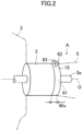
- Fig. 2 is a perspective view of the drive unit A.
- the drive unit A includes the motor 3 and the inverter 15.
- the motor 3 and the inverter 15 are disposed adjacent and coaxially to each other in the axial direction of the motor 3. Specifically, a center axis O of the motor 3 and a center axis O of the inverter 15 coincide with each other.
- the motor 3 (specifically, a casing of the motor 3) is formed with a cylindrical shape.
- the inverter 15 (specifically, a casing of the inverter 15) is formed with a cylindrical shape corresponding to that of the motor 3.
- a rotation shaft 3a of the motor 3 extends through the inverter 15 in the axial direction.
- a thickness Wiv of the inverter 15 is small, and is, for example, 50 mm or less (preferably, 30 mm or less).
- a cooling path 61 (described later) is provided inside the inverter 15.
- a cooling inlet pipe 62 and a cooling outlet pipe 63 that communicate with the cooling path 61 are connected to an upper portion of the inverter.
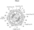
- Fig. 3 is a cross sectional view of the motor 3 when seen from the inverter 15.
- the motor 3 has coils 17. Specifically, each coil 17 is wound in a concentrated manner on a stator of the motor 3 so that two U-phase coils 17u, two V-phase coils 17v, and two W-phase coils 17w are disposed. Each coil 17 is disposed side by side uniformly in a peripheral direction of the motor 3.
- U-phase coils 17u a first U-phase coil 17u1 and a second U-phase coil 17u2 are provided.
- V-phase coils 17v a first V-phase coil 17v1 and a second V-phase coil 17v2 are provided.
- W-phase coils 17w a first W-phase coil 17w1 and a second W-phase coil 17w2 are provided.
- a first coil group C1 and a second coil group C2 are provided.
- the first coil group C1 includes the first U-phase coil 17u1, the first V-phase coil 17v1, and the first W-phase coil 17w1.
- the second coil group C2 includes the second U-phase coil 17u2, the second V-phase coil 17v2, and the second W-phase coil 17w2.
- Each of the phase coils 17u1, 17v1, and 17w1 of the first coil group C1 is disposed on one side in a radial direction of the motor 3.
- Each of the phase coils 17u2, 17v2, and 17w2 of the second coil group C2 is disposed on the other side in the radial direction of the motor 3.
- the first U-phase coil 17u1 of the first coil group C1 and the second U-phase coil 17u2 of the second coil group C2 oppose each other in the radial direction of the motor 3.
- the first V-phase coil 17v1 of the first coil group C1 and the second V-phase coil 17v2 of the second coil group C2 oppose each other in the radial direction of the motor 3.
- the first W-phase coil 17w1 of the first coil group C1 and the second W-phase coil 17w2 of the second coil group C2 oppose each other in the radial direction of the motor 3.
- each motor-side terminal block 18 is disposed at a corresponding peripheral-direction position and at a radial-direction outer side with respect to a corresponding one of the coils 17.
- a lead wire extends from each coil 17.
- Each lead wire is connected to a corresponding one of the motor-side terminal blocks 18.
- an iron core 27 and a permanent magnet 28 having a N pole and a S pole are fixed to the rotation shaft 3a.
- Fig. 4 is a circuit diagram of the inverter 15.
- the inverter 15 includes a smoothing capacitor 19 and a plurality of power modules 20.
- the smoothing capacitor 19 smoothens a voltage that is applied to the power modules 20.
- the plurality of power modules 20 constitute an inverter circuit, and convert direct-current voltage into an alternating-current voltage.
- U-phase power modules 20u As the plurality of power modules 20, U-phase power modules 20u, V-phase power modules 20v, and W-phase power modules 20w are provided.
- the U-phase power modules 20u correspond to the U-phase coils 17u.
- the V-phase power modules 20v correspond to the V-phase coils 17v.
- the W-phase power modules 20w correspond to the W-phase coils 17w.
- U-phase power modules 20u a first U-phase power module 20u1 and a second U-phase power module 20u2 are provided.
- V-phase power modules 20v a first V-phase power module 20v1 and a second V-phase power module 20v2 are provided.
- W-phase power modules 20w a first W-phase power module 20w1 and a second W-phase power module 20w2 are provided.
- the plurality of power modules 20 constitute a first power module group P1 and a second power module group P2 that are connected in parallel.
- the first power module group P1 and the second power module group P2 each include one U-phase power module 20u, one V-phase power module 20v, and one W-phase power module 20w.
- the first power module group P1 includes the first U-phase power module 20u1, the first V-phase power module 20v1, and the first W-phase power module 20w1.
- the phase power modules 20u1, 20v1, and 20w1 of the first power module group P1 are connected to the phase coils 17u1, 17v1, and 17w1 of the first coil group C1, respectively.
- the first U-phase power module 20u1 of the first power module group P1 is connected to the first U-phase coil 17u1 of the first coil group C1.
- the first V-phase power module 20v1 of the first power module group P1 is connected to the first V-phase coil 17v1 of the first coil group C1.
- the first W-phase power module 20w1 of the first power module group P1 is connected to the first W-phase coil 17w1 of the first coil group C1.
- the second power module group P2 includes the second U-phase power module 20u2, the second V-phase power module 20v2, and the second W-phase power module 20w2.
- the phase power modules 20u2, 20v2, and 20w2 of the second power module group P2 are connected to the phase coils 17u2, 17v2, and 17w2 of the second coil group C2, respectively.
- the second U-phase power module 20u2 of the second power module group P2 is connected to the second U-phase coil 17u2 of the second coil group C2.
- the second V-phase power module 20v2 of the second power module group P2 is connected to the second V-phase coil 17v2 of the second coil group C2.
- the second W-phase power module 20w2 of the second power module group P2 is connected to the second W-phase coil 17w2 of the second coil group C2.
- Each power module 20 includes two arm elements, that is, a lower arm element 21 and an upper arm element 22, serving as switching elements.
- a lower arm element 21 and an upper arm element 22 serving as switching elements.
- the other of the lower arm element 21 and the upper arm element 22 is closed. Therefore, a three-phase alternating current is supplied to the motor 3.
- each power module 20 includes a SiC-MOSFET.
- Fig. 5 shows a comparison between a SiC-MOSFET and an IGBT.
- the SiC-MOSFET is a MOSFET (metal-oxide-semiconductor field-effect transistor) including silicon carbide (SiC), and constitutes a chip 24 including the lower arm element 21 and the upper arm element 22 and, for example, other control elements.
- a lower surface of the chip 24 is soldered and fixed to a silicon substrate.
- a copper block 25, serving as a heat transfer block, is soldered and fixed to an upper surface of the chip 24. This also applies to the IGBT (insulated gate bipolar transistor).
- a surface area of the chip 24 constituted by the SiC-MOSFET is smaller than a surface area of a chip 24' constituted by the IGBT. Therefore, the size of the copper block 25 disposed on an upper side of the SiC-MOSFET (chip) 24 is smaller than the size of a copper block 25' disposed on an upper side of the IGBT (chip) 24'.
- the SiC-MOSFET has better heat resistance than the IGBT.
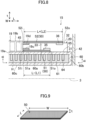
- Fig. 6 is a perspective view and a circuit diagram of a detailed structure of a power module 20.
- Each power module 20 has a flat shape having a wide width. Specifically, each power module 20 is longer in a width direction W than in a thickness direction t.
- Each power module 20 has a substantially parallelepiped shape.
- the width direction W includes a first width direction W1 and a second width direction W2 orthogonal to each other.
- one side of the power module 20 in the thickness direction may be the lower side and the other side of the power module 20 in the thickness direction may be the upper side.
- the power module 20 has a lower surface 31 on the lower side (one surface side, the one side in the thickness direction).
- the power module 20 has an upper surface 32 on the upper side.
- the power module 20 has a first end surface 33 on one side in the first width direction W1.
- the power module 20 has a second end surface 34 on the other side in the first width direction W1.
- a negative-electrode-side input terminal 35 is connected to a lower side of the first end surface 33 and on one side in the second width direction W2.
- a positive-electrode-side input terminal 36 is connected to an upper side of the first end surface 33 and on the other side in the second width direction W2.
- the negative-electrode-side input terminal 35 and the positive-electrode-side input terminal 36 are disposed apart from each other in an up-down direction (thickness direction).
- An output terminal 37 is connected to a central portion of the second end surface 34.
- the lower arm element 21 and the upper arm element 22 are accommodated inside a package (box body) of the power module 20.
- the negative-electrode-side input terminal 35 is connected to the lower arm element 21.
- the positive-electrode-side input terminal 36 is connected to the upper arm element 22.
- the output terminal 37 is connected between the lower arm element 21 and the upper arm element 22.
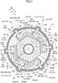
- Fig. 7 is a cross sectional view of the inverter 15 when seen from a side opposite to the motor 3.
- Fig. 8 is a vertical sectional view of the inverter 15 along line VIII-VIII.
- an axial through hole 40 through which the rotation shaft 3a of the motor 3 passes is provided in the center of the inverter 15.
- a cylindrical boss portion 41 is formed around the axial through hole 40.
- the smoothing capacitor 19 is disposed at a center O of the inverter 15.
- the smoothing capacitor 19 is disposed along the boss portion 41.
- the smoothing capacitor 19 is formed with a hollow polygonal shape having an axial through hole through which the rotation shaft 3a passes.
- Each power module 20 (the first U-phase power module 20u1, the first V-phase power module 20v1, the first W-phase power module 20w1, the second U-phase power module 20u2, the second V-phase power module 20v2, and the second W-phase power module 20w2) are disposed on an outer peripheral side with respect to the smoothing capacitor 19.
- each power module 20 is disposed side by side in the peripheral direction of the motor 3.
- the input terminals 35 and 36 (the first end surface 33) and the output terminal 37 (the second end surface 34) of each power module 20 face the peripheral direction of the motor 3 (the inverter 15).
- Each power module 20 is disposed so that the thickness direction t coincides with the axial direction of the motor 3.
- the smoothing capacitor 19 and each power module 20 are disposed in a space defined by an outer peripheral wall portion 42 and the boss portion 41 of the inverter 15.
- Each of the phase power modules 20u1, 20v1, and 20w1 of the first power module group P1 is disposed on one side in the radial direction of the motor 3 (the inverter 15).
- Each of the phase power modules 20u2, 20v2, and 20w2 of the second power module group P2 is disposed on the other side in the radial direction of the motor 3.
- the first U-phase power module 20u1 of the first power module group P1 and the second U-phase power module 20u2 of the second power module group P2 oppose each other in the radial direction of the motor 3 (the inverter 15).
- the first V-phase power module 20v1 of the first power module group P1 and the second V-phase power module 20v2 of the second power module group P2 oppose each other in the radial direction of the motor 3.
- the first W-phase power module 20w1 of the first power module group P1 and the second W-phase power module 20w2 of the second power module group P2 oppose each other in the radial direction of the motor 3.
- a heat sink 60 is provided on a motor-3 side of the inverter 15.
- the heat sink 60 is primarily used for cooling each power module 20.
- the heat sink 60 is disposed between the outer peripheral wall portion 42 and the boss portion 41 of the inverter 15.
- the heat sink 60 has an upper wall portion 60a, an outer peripheral wall portion 60b, a lower wall portion 60c, and an inner peripheral wall portion 60d.
- An upper surface 65 of the upper wall portion 60a of the heat sink 60 constitutes a placement surface orthogonal to the axial direction of the motor 3 (may hereunder be referred to as "placement surface 65").
- a lower surface 31 of each power module 20 faces the motor 3. Specifically, the lower surface 31 of each power module 20 is placed side by side on the same placement surface 65.
- the smoothing capacitor 19 is one in which an assembly of a plurality of columnar capacitors 45 is covered by a flat plate from both sides in the thickness direction.
- the smoothing capacitor 19 has a lower surface 19a on a lower side (one surface side, the one side in the thickness direction).
- the smoothing capacitor 19 has an upper surface 19b on a side opposite to the lower surface 19a.
- the lower surface 19a and the upper surface 19b of the smoothing capacitor 19 are constituted by flat plates.
- the lower surface 19a of the smoothing capacitor 19 faces the motor 3. Specifically, the lower surface 19a of the smoothing capacitor 19 is placed on the placement surface 65.
- the smoothing capacitor 19 and each power module 20 are connected to each other by a negative-electrode-side busbar 51 and a positive-electrode-side busbar 52, serving as input busbars 50 (may hereunder be simply referred to as "busbars 50").
- the negative-electrode-side busbar 51 and the positive-electrode-side busbar 52 each have a plate shape. Specifically, the negative-electrode-side busbar 51 and the positive-electrode-side busbar 52 are longer in the width direction W and a length direction L than in the thickness direction t.
- the negative-electrode-side busbar 51 and the positive-electrode-side busbar 52 are formed with wide widths so as to be extend along the peripheral direction of the motor 3 (the inverter 15).
- the negative-electrode-side busbar 51 and the positive-electrode-side busbar 52 are formed with wide widths so as to extend along a direction in which each power module 20 is disposed side by side.
- the width direction W of the negative-electrode-side busbar 51 and the positive-electrode-side busbar 52 is the peripheral direction of the motor 3 (an arc shape is formed).
- the negative-electrode-side busbar 51 and the positive-electrode-side busbar 52 each have a fan shape.
- the length direction L of the negative-electrode-side busbar 51 and the positive-electrode-side busbar 52 is the radial direction of the motor 3.
- One end portion 51i of the negative-electrode-side busbar 51 (input busbar 50) is connected to a negative-electrode terminal 19c provided on a lower-surface-19a side of the smoothing capacitor 19.
- the other end portion 51o of the negative-electrode-side busbar 51 (input busbar 50) is connected to a negative-electrode-side input terminal 35 of each power module 20.
- One end portion 52i of the positive-electrode-side busbar 52 (input busbar 50) is connected to a positive-electrode terminal 19d provided on an upper-surface-19b side of the smoothing capacitor 19.
- the other end portion 52o of the positive-electrode-side busbar 52 (input busbar 50) is connected to a positive-electrode-side input terminal 36 of each power module 20.
- the negative-electrode-side busbar 51 has a lower surface 51a on the lower side (one surface side, the one side in the thickness direction).
- the lower surface 51a of the negative-electrode-side busbar 51 faces the motor 3. Specifically, the lower surface 51a of the negative-electrode-side busbar 51 is placed on the placement surface 65.
- output busbars 54 are each connected to the output terminal 37 of a corresponding one of the power modules 20.
- the output busbars 54 are each interposed between the corresponding one of the power modules 20 and a corresponding one of the coils 17.
- the output busbars 54 each have a plate shape.
- a wire harness or the like may be interposed between the corresponding one of the power modules 20 and the corresponding one of the coils 17.
- each inverter-side terminal block 46 is disposed at a corresponding peripheral-direction position and at a radial-direction outer side with respect to a corresponding one of the power modules 20.
- the output busbars 54 extend up to the respective inverter-side terminal blocks 46. Electrically conductive members (busbars, wire harnesses, or the like) are each interposed between a corresponding one of the inverter-side terminal blocks 46 and a corresponding one of the motor-side terminal blocks 18.
- the cooling path (cooling jacket) 61 is provided inside the heat sink 60.
- the cooling path 61 is defined by the upper wall portion 60a, the outer peripheral wall portion 60b, the lower wall portion 60c, and the inner peripheral wall portion 60d.
- the cooling path 61 is formed with a doughnut shape (ring shape, cylindrical shape) over the entire periphery when seen in the axial direction of the motor 3 (the inverter 15) (see Fig. 7 ).
- the rotation shaft 3a of the motor 3 passes through an inner side of the inner peripheral wall portion 60d.
- the upper surface of the upper wall portion 60a of the heat sink 60 is the placement surface 65.
- the cooling path 61 is provided closer to the motor 3 than the placement surface 65.
- a cooling medium H flows in the cooling path 61.
- the cooling medium H is, for example, cooling water or cooling oil.
- a plurality of fins 64 are provided inside the heat sink 60 (the cooling path 61).
- the fins 64 extend downward inside the cooling path 61 from the upper wall portion 60a. That is, the fins 64 are provided closer to the motor 3 than the placement surface 65.
- the cooling path 61 faces the lower surface 31 of each power module 20, the lower surface 51a of the negative-electrode-side busbar 51, and the lower surface 19a of the smoothing capacitor 19.
- the fins 64 face the lower surface 31 of each power module 20, the lower surface 51a of the negative-electrode-side busbar 51, and the lower surface 19a of the smoothing capacitor 19.
- the inlet pipe 62 and the outlet pipe 63 are connected to an upper portion of the outer peripheral portion of the inverter 15.
- the inlet pipe 62 and the outlet pipe 63 communicate with the cooling path 61.
- the cooling medium H introduced into the cooling path 61 via the inlet pipe 62 is discharged to the outside via the outlet pipe 63 after having flowed inside the cooling path 61.
- Fig. 9 is a perspective view of a busbar 50.
- Fig. 10 shows graphs showing the relationship between size and inductance sensitivity of busbar 50.
- a minimum value (inflection point) M exists in the relationship between the length L (mm) and the inductance sensitivity (nH) of busbar 50. Therefore, even if lengths L differ from each other, the inductance sensitivity (nH) may become the same.
- the inductance sensitivity (nH) of busbar 50 (51, 52) is a function of the length L (mm) extending from the one end portion 51i or 52i of busbar 50 (51, 52) (the terminal 19c or 19d of the smoothing capacitor 19) to the other end portion 51o or 52o of busbar 50 (51, 52) (the input terminal 35 or 36 of each power module 20).
- the function has the minimum value M so that the inductance sensitivity K (nH) becomes the same at a first length L1 (mm) and a second length L2 (mm) that differ from each other.
- the second length L2 (mm) is larger than the first length L1 (mm).
- busbar 50 Even if a thickness t (mm) of busbar 50 changes, the inductance sensitivity (nH) of busbar 50 does not change.
- the width of the negative-electrode-side busbar 51 and the width of the positive-electrode-side busbar 52 are substantially the same.
- a length L- of the negative-electrode-side busbar 51 and a length L+ of the positive-electrode-side busbar 52 differ from each other.
- the length L- of the negative-electrode-side busbar 51 corresponds to the first length L1.
- the length L+ of the positive-electrode-side busbar 52 corresponds to the second length L2.
- the length L+ of the positive-electrode-side busbar 52 (the second length L2) is larger than the length L- of the negative-electrode-side busbar 51 (the first length L1).
- the inductance sensitivity of the negative-electrode-side busbar 51 and the inductance sensitivity of the positive-electrode-side busbar 52 are equal to each other.
- the first U-phase power module 20u1 of the first power module group P1 when seen in the axial direction of the motor 3 (the inverter 15), the first U-phase power module 20u1 of the first power module group P1 is disposed at a position overlapping the first U-phase coil 17u1 of the first coil group C1.
- the first V-phase power module 20v1 of the first power module group P1 is disposed at a position overlapping the first V-phase coil 17v1 of the first coil group C1.
- the first W-phase power module 20w1 of the first power module group P1 is disposed at a position overlapping the first W-phase coil 17w1 of the first coil group C1.
- the second U-phase power module 20u2 of the second power module group P2 when seen in the axial direction of the motor 3 (the inverter 15), the second U-phase power module 20u2 of the second power module group P2 is disposed at a position overlapping the second U-phase coil 17u2 of the second coil group C2.
- the second V-phase power module 20v2 of the second power module group P2 is disposed at a position overlapping the second V-phase coil 17v2 of the second coil group C2.
- the second W-phase power module 20w2 of the second power module group P2 is disposed at a position overlapping the second W-phase coil 17w2 of the second coil group C2.
- each power module 20 is disposed so as to overlap at least a part of the corresponding one of the coils 17.
- a distance du1 between the first U-phase power module 20u1 of the first power module group P1 and the first U-phase coil 17u1 of the first coil group C1, a distance dv1 between the first V-phase power module 20v1 of the first power module group P1 and the first V-phase coil 17v1 of the first coil group C1, and a distance dw1 between the first W-phase power module 20w1 of the first power module group P1 and the first W-phase coil 17w1 of the first coil group C1 are equal to each other.
- a distance du2 between the second U-phase power module 20u2 of the second power module group P2 and the second U-phase coil 17u2 of the second coil group C2 a distance dv2 between the second V-phase power module 20v2 of the second power module group P2 and the second V-phase coil 17v2 of the second coil group C2
- a distance dw2 between the second W-phase power module 20w2 of the second power module group P2 and the second W-phase coil 17w2 of the second coil group C2 are equal to each other.
- the distance du1 between the first U-phase power module 20u1 of the first power module group P1 and the first U-phase coil 17u1 of the first coil group C1 and the distance du2 between the second U-phase power module 20u2 of the second power module group P2 and the second U-phase coil 17u2 of the second coil group C2 are equal to each other.
- the distance dv1 between the first V-phase power module 20v1 of the first power module group P1 and the first V-phase coil 17v1 of the first coil group C1 and the distance dv2 between the second V-phase power module 20v2 of the second power module group P2 and the second V-phase coil 17v2 of the second coil group C2 are equal to each other.
- the distance dw1 between the first W-phase power module 20w1 of the first power module group P1 and the first W-phase coil 17w1 of the first coil group C1 and the distance dw2 between the second W-phase power module 20w2 of the second power module group P2 and the second W-phase coil 17w2 of the second coil group C2 are equal to each other.
- the distances du1, dv1, dw1, du2, dv2, and dw2 are all zero. Any standard may be set for the distances du1, dv1, dw1, du2, dv2, and dw2.
- the output of the motor 3 can be increased.
- each power module 20 is placed side by side on the same placement surface 65 orthogonal to the axial direction of the motor 3, the axial-direction length of the inverter 15 can be suppressed from being increased even though the number of power modules 20 has been increased.
- the motor 3 and the inverter 15 are disposed adjacent to each other in the axial direction of the motor 3, the distance between the phase power modules 20 and the respective phase coils 17 can be reduced. Therefore, inductances of electrical paths (including the output busbars 54) extending from the phase power modules 20 to the respective phase coils 17 can be reduced.
- the distances du1, dv1, and dw1 between a corresponding one of the phase power modules 20u1, 20v1, and 20w1 and a corresponding one of the phase coils 17u1, 17v1, and 17w1 are equal to each other between the U phase, the V phase, and the W phase.
- the inductances of the electrical paths (including the output busbars 54) extending from the phase power modules 20u1, 20v1, and 20w1 to the respective phase coils 17u1, 17v1, and 17w1 can be equalized between the U phase, the V phase, and the W phase.
- the output of the motor 3 is increased, and the inductances of the electrical paths extending from the phase power modules 20 to the respective phase coils 17 can be reduced and equalized.
- the distances du2, dv2, and dw2 between a corresponding one of the phase power modules 20u2, 20v2, and 20w2 and a corresponding one of the phase coils 17u2, 17v2, and 17w2 are equal to each other between the U phase, the V phase, and the W phase.
- inductances of electrical paths (including the output busbars 54) extending from the phase power modules 20u2, 20v2, and 20w2 to the respective phase coils 17u2, 17v2, and 17w2 can be equalized between the U phase, the V phase, and the W phase.
- the inductances of the electrical paths (including the output busbars 54) extending from the phase power modules 20u1, 20v1, 20w1, 20u2, 20v2, and 20w2 to the respective phase coils 17u1, 17v1, 17w1, 17u2, 17v2, and 17w2 can be equalized.
- the phase power modules 20u1, 20v1, and 20w1 of the first power module group P1 are disposed at positions overlapping the respective phase coils 17u1, 17v1, and 17w1 of the first coil group C1. Therefore, in the first power module group P1 and the first coil group C1, the distances du1, dv1, and dw1 between the corresponding one of the phase power modules 20u1, 20v1, and 20w1 and the corresponding one of the phase coils 17u1, 17v1, and 17w1 can be reduced.
- the inductances of the electrical paths (including the output busbars 54) extending from the phase power modules 20u1, 20v1, and 20w1 to the respective phase coils 17u1, 17v1, and 17w1 can be reduced.
- the phase power modules 20u2, 20v2, and 20w2 of the second power module group P2 are disposed at positions overlapping the respective phase coils 17u2, 17v2, 17w2 of the second coil group C2. Therefore, even in the second power module group P2 and the second coil group C2, as in the first power module group P1 and the first coil group C1, the distances du2, dv2, and dw2 between the corresponding one of the phase power modules 20u2, 20v2, and 20w2 and the corresponding one of the phase coils 17u2, 17v2, and 17w2 can be reduced.
- coils 17 of the same phase are often disposed so as to oppose each other in the radial direction of the motor 3 (see Fig. 3 ).
- power modules 20 of the same phase are disposed so as to oppose each other in the radial direction of the motor 3. Therefore, the phase power modules 20 are easily positioned with respect to the respective phase coils 17.
- each power module 20 is disposed side by side in the peripheral direction of the motor 3 on the outer peripheral side with respect to the smoothing capacitor 19, the distances between the smoothing capacitor 19 and each power module 20 can be made equal to each other. Further, since the input busbars 50 (the negative-electrode-side busbar 51 and the positive-electrode-side busbar 52) are formed with wide widths so as to be extend along the peripheral direction of the motor 3, in the input busbars 50, inductances of electrical paths between the smoothing capacitor 19 and each power module 20 can be equalized.
- the input busbars 50 (the negative-electrode-side busbar 51 and the positive-electrode-side busbar 52) that connect the smoothing capacitor 19 and each power module 20 to each other, by using the minimum value (the inflection point) M (see Fig. 10 ), even though the length L- of the negative-electrode-side busbar 51 (the first length L1) and the length L+ of the positive-electrode-side busbar 52 (the second length L2) differ from each other, the inductance of the negative-electrode-side busbar 51 and the inductance of the positive-electrode-side busbar 52 can be equalized with respect to each other.
- an inverter 15' is often disposed near a second battery unit 12b' of a battery 12'.
- the inverter 15 since the inverter 15 can be disposed adjacent to the motor 3 in the axial direction, the inverter 15 no longer needs to be disposed near the second battery unit 12b. Therefore, the layout of the second battery unit 12b can be provided with greater freedom, and the second battery unit 12b can be increased in size.
- the phase power modules 20u1, 20v1, and 20w1 of the first power module group P1 are disposed at positions overlapping the respective phase coils 17u1, 17v1, and 17w1 of the first coil group C1. Therefore, in the first power module group P1 and the first coil group C1, this is advantageous in terms of equalizing the inductances of the electrical paths extending from the phase power modules 20u1, 20v1, and 20w1 to the respective phase coils 17u1, 17v1, and 17w1 between the U phase, the V phase, and the W phase.
- the phase power modules 20u2, 20v2, and 20w2 of the second power module group P2 are disposed at positions overlapping the respective phase coils 17u2, 17v2, and 17w2 of the second coil group C2. Therefore, even in the second power module group P2 and the second coil group C2, as in the first power module group P1 and the first coil group C1, this is advantageous in terms of equalizing the inductances of the electrical paths extending from the phase power modules 20u2, 20v2, and 20w2 to the respective phase coils 17u2, 17v2, and 17w2 between the U phase, the V phase, and the W phase.
- Fig. 11 is a view, corresponding to Fig. 7 , of Modification 1 of the first embodiment.
- the phase power modules 20u1, 20v1, 20w1, 20u2, 20v2, and 20w2 are disposed at locations that do not overlap the respective phase coils 17u1, 17v1, 17w1, 17u2, 17v2, and 17w2.
- phase power modules 20u1, 20v1, 20w1, 20u2, 20v2, and 20w2 are displaced form the respective phase coils 17u1, 17v1, 17w1, 17u2, 17v2, and 17w2 in the peripheral direction of the motor 3.
- the distances du1, dv1, dw1, du2, dv2, and dw2 between the corresponding one of the phase power modules 20u1, 20v1, 20w1, 20u2, 20v2, and 20w2 and the corresponding one of the phase coils 17u1, 17v1, 17w1, 17u2, 17v2, and 17w2 are equal to each other, and are d (> 0).
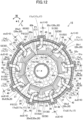
- Fig. 12 is a view, corresponding to Fig. 7 , of Modification 2 of the first embodiment.
- the stator of the motor 3 is further provided with a third U-phase coil 17u3, serving as a U-phase coil 17u, a third V-phase coil 17v3, serving as a V-phase coil 17v, and a third W-phase coil 17w3, serving as a W-phase coil 17w.
- the third U-phase coil 17u3, the third V-phase coil 17v3, and the third W-phase coil 17w3 constitute a third coil group C3.
- the inverter 15 further includes a third U-phase power module 20u3, serving as a U-phase power module 20u, a third V-phase power module 20v3, serving as a V-phase power module 20v, and a third W-phase power module 20w3, serving as a W-phase power module 20w.
- the third U-phase power module 20u3, the third V-phase power module 20v3, and the third W-phase power module 20w3 constitute a third power module group P3.
- phase power modules 20u1, 20v1, 20w1, 20u2, 20v2, 20w2, 20u3, 20v3, and 20w3 are disposed at positions overlapping the respective phase coils 17u1, 17v1, 17w1, 17u2, 17v2, 17w2, 17u3, 17v3, and 17w3.
- the distances du1, dv1, dw1, du2, dv2, dw2, du3, dv3, and dw3 between a corresponding one of the phase power modules 20u1, 20v1, 20w1, 20u2, 20v2, 20w2, 20u3, 20v3, and 20w3 and a corresponding one of the phase coils 17u1, 17v1, 17w1, 17u2, 17v2, 17w2, 17u3, 17v3, and 17w3 are equal to each other, and are zero.
- the output of the motor 3 can be further increased by connecting the first power module group P1, the second power module group P2, and the third power module group P3 by three parallel connection.
- Fig. 13A is a view, corresponding to Fig. 7 , of Modification 3 of the first embodiment.
- the inverters 16 according to the present modification are disposed adjacent to the respective in-wheel motors 14 in the axial direction of the in-wheel motors 14 (see Fig. 1 ).
- the inverters 16 do not have an axial through hole 40 and a boss portion 41.
- the smoothing capacitor 19 has a columnar shape.
- the smoothing capacitor 19 does not have an axial through hole.
- Fig. 13B shows an output busbar 54 according to Modification 4 of the first embodiment.
- each output busbar 54 is formed with a wide width so as to extend along the peripheral direction of the motor 3.
- the width direction of each output busbar 54 is the peripheral direction (an arc shape is formed).
- Each output busbar 54 has a fan shape. Therefore, since each output busbar 54 is easily formed with a wide width, the inductance of each output busbar 54 is easily reduced.
- the number of coil groups of the motor 3 and the number of power module groups of the inverter 15 may differ from each other. For example, when the number of coil groups of the motor 3 is three (the number of coils is nine), the number of power module groups of the inverter 15 may be two (the number of power modules may be six). In contrast, when the number of coil groups of the motor 3 is two (the number of coils is six), the number of power module groups of the inverter 15 may be three (the number of power modules 20 may be nine).
- the U-phase coils 17u, the V-phase coils 17v, and the W-phase coils 17w may be subjected to distributed winding.
- the length L- of the negative-electrode-side busbar 51 may be the second length L2
- the length L+ of the positive-electrode-side busbar 52 may be the first length L1.
- the placement surface 65 may include a plurality of surfaces that are positioned in the same plane orthogonal to the axial direction of the motor 3.
- Fig. 14 is a view, corresponding to Fig. 7 , of a second embodiment, and is a cross sectional view of an inverter 15 when seen from a side opposite to a motor 3.
- Fig. 15 is a view, corresponding to Fig. 8 , of the second embodiment, and is a vertical sectional view of the inverter 15. A detailed description of structures that are the same as those of the embodiment above may not be given.
- each power module 20 is disposed on an outer peripheral side with respect to a smoothing capacitor 19. On the outer peripheral side with respect to the smoothing capacitor 19, the power modules 20 are disposed side by side in a peripheral direction of the motor 3.
- Input terminals 35 and 36 (first end surface 33) and an output terminal 37 (second end surface 34) of each power module 20 face a radial direction of the motor 3 (the inverter 15). Specifically, the input terminals 35 and 36 (the first end surface 33) of each power module 20 face an inner peripheral side. The output terminal 37 (the second end surface 34) of each power module 20 faces the outer peripheral side. Each power module 20 is disposed radially from a center O, which is an origin, of the inverter 15 (the motor 3) .
- the width of a negative-electrode-side busbar 51 and the width of a positive-electrode-side busbar 52 are the same.
- a length L- of the negative-electrode-side busbar 51 and a length L+ of the positive-electrode-side busbar 52 are the same. Therefore, the inductance of the negative-electrode-side busbar 51 and the inductance of the positive-electrode-side busbar 52 are equal to each other.
- Fig. 16 is a view, corresponding to Fig. 7 , of a third embodiment, and is a cross sectional view of an inverter 15 when seen from a side opposite to a motor 3.
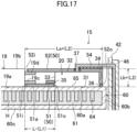
- Fig. 17 is a view, corresponding to Fig. 8 , of the third embodiment, and is a vertical sectional view of the inverter 15. A detailed description of structures that are the same as those of the embodiments above may not be given.
- negative-electrode-side input terminals 35 are each connected to a lower side of a first end surface 33 of a corresponding one of power modules 20.
- Positive-electrode-side input terminals 36 are each connected to a lower side of a second end surface 34 of the corresponding one of the power modules 20.
- Output terminals 37 are each connected to the center of an upper surface 32 of the corresponding one of the power modules 20.
- a negative-electrode-side busbar 51 connects a negative-electrode terminal 19c of a smoothing capacitor 19 and the negative-electrode-side input terminal 35 of each power module to each other.
- a positive-electrode-side busbar 52 connects a positive-electrode terminal 19d of the smoothing capacitor 19 and the positive-electrode-side input terminal 36 of each power module 20 to each other.
- the positive-electrode-side busbar 52 starts out from the positive-electrode terminal 19d of the smoothing capacitor 19 (one end portion 52i), and extends along the upper surface 32 to the second end surface 34 from the first end surface 33 of each power module 20. Then, the positive-electrode-side busbar 52 bends downward and extends along the second end surface 34 up to the positive-electrode-side input terminal 36 (other end portion 52o) on the lower side of each power module 20. In other words, the positive-electrode-side busbar 52 extends so as to be wound around each power module 20 from the upper surface 32.
- Each output busbar 54 starts out from an output terminal 37 at the upper surface 32 of each power module 20, and extends upward.
- the positive-electrode-side busbar 52 has three opening portions for passing three upwardly extending output busbars 54 therethrough.
- the width of the negative-electrode-side busbar 51 and the width of the positive-electrode-side busbar 52 are the same.
- the length (L-) of the negative-electrode-side busbar 51 and the length (sum of La+ and Lb+) of the positive-electrode-side busbar 52 differ from each other.
- the length (L-) of the negative-electrode-side busbar 51 corresponds to the first length L1.
- the length (sum of La+ and Lb+) of the positive-electrode-side busbar 52 corresponds to the second length L2.
- the length (sum of La+ and Lb+, the second length L2) of the positive-electrode-side busbar 52 is larger than the length (L-, the first length L1) of the negative-electrode-side busbar 51.
- the inductance of the negative-electrode-side busbar 51 and the inductance of the positive-electrode-side busbar 52 are equal to each other.
- the conditions (for example, materials) of the negative-electrode-side busbar 51 and the positive-electrode-side busbar 52 according to the present embodiment differ from those of the embodiments above. Therefore, the mode of the minimum value (M above) (see Fig. 10 ) also differs. Specifically, the difference between the first length L1 and the second length L2 is larger than that in the embodiments above.
- Fig. 18 is a view, corresponding to Fig. 8 , of Modification 1 of the third embodiment, and is a vertical sectional view of an inverter 15.
- each power module 20 accommodates both the lower arm element 21 and the upper arm element 22 in one package
- the present modification differs.
- each power module 20 is separated into a first package 20a that accommodates the lower arm element 21 and a second package 20b that accommodates the upper arm element 22.
- Fig. 19 is a perspective view of power modules 20 and busbars 50 according to Modification 2 of the third embodiment.
- each power module 20 is linearly disposed side by side.
- the width direction of each of the busbars 51 and 52 is a linear direction (direction in which each power module 20 is disposed side by side).
- the distances du1, dv1, and dw1 between the corresponding one of the phase power modules 20u1, 20v1, and 20w1 and the corresponding one of the phase coils 17u1, 17v1, and 17w1 are to be equal to each other between the U phase, the V phase, and the W phase.
- the present disclosure is applicable to a vehicle drive unit, and thus is very effective and has high industrial applicability.
Landscapes
- Engineering & Computer Science (AREA)
- Power Engineering (AREA)
- Life Sciences & Earth Sciences (AREA)
- Sustainable Development (AREA)
- Sustainable Energy (AREA)
- Transportation (AREA)
- Mechanical Engineering (AREA)
- Microelectronics & Electronic Packaging (AREA)
- Inverter Devices (AREA)
- Motor Or Generator Cooling System (AREA)
Abstract
Description
- The present disclosure relates to a vehicle drive unit including a motor and an inverter.
- A drive unit that drives a motor by converting direct current from a battery into alternating current by an inverter is known. The inverter has a power module including a switching element. An inverter disclosed in
Japanese Unexamined Patent Application Publication No. 2021-112011 - Since an inverter of this type handles high electric power, a high voltage is applied and a large current flows. Therefore, the heat generation amount at the time of operation is large, and thus cooling is required. A high surge voltage is also generated. Therefore, individual electronic components of the inverter become large, and also tend to be heavy. Consequently, the inverter of the related art is a factor that prevents fuel costs and electricity costs from being reduced.
- In order to reduce a power transmission distance, the inverter is ordinarily disposed near a drive motor. However, in the case of a car, there are many devices to be installed and thus a space in which the inverter can be disposed is limited. It is also necessary to consider the balance of a car body. Therefore, it is difficult to adequately dispose a large, heavy inverter in a car.
- With regard to such a problem, in
Japanese Unexamined Patent Application Publication No. 2021-112011 - Each phase power module of the inverter is connected to a corresponding one of the phase coils of the motor via an electrical connection member. Since a large current flows in the electrical connection member, the electrical connection member is large and heavy. When a wiring length of the electrical connection member increases, the electrical resistance increases correspondingly, and thus copper loss occurs at the time of energization. The electrical connection member generates a large amount of heat. Moreover, in the inverter, since the large current is set in an on/off state at a high speed by switching control, a large magnetic change occurs in the electrical connection member.
- Therefore, when the inverter operates, noise, vibration, electromagnetic interference, and the like occur at the electrical connection member due to the magnetic change. The noise, vibration, electromagnetic interference, and the like result in energy loss and variously adversely affect the performance of the car, as a result of which measures need to be taken.
- Therefore, from the viewpoint of motor control, it is important to reduce inductances of electrical paths extending from the phase power modules to the respective phase coils of the motor, and to equalize the inductances between the U phase, the V phase, and the W phase. In particular, when the output of the motor is large, it is important to reduce and equalize the inductances of the electrical paths.
- On the other hand, in order to increase the output of the motor, it is important to increase the number of power modules of the inverter. However, an increase in the size of the inverter caused by an increase in the number of power modules is to be avoided.
- The present disclosure has been made in view of such points, and it is an object of the present disclosure to, while suppressing a drive unit including a motor and an inverter from increasing in size, increase an output of a motor, and reduce and equalize inductances of electrical paths extending from phase power modules to respective phase coils.
- A vehicle drive unit according to a first aspect of the present disclosure is a vehicle drive unit in which a motor and an inverter having a plurality of power modules are disposed adjacent to each other in an axial direction of the motor. In the vehicle drive unit, each power module is placed on a placement surface orthogonal to the axial direction; in the motor, as coil groups each including one U-phase coil, one V-phase coil, and one W-phase coil, at least a first coil group and a second coil group are provided; the plurality of power modules constitute at least a first power module group and a second power module group that are connected in parallel; the first power module group and the second power module group each include one U-phase power module, one V-phase power module, and one W-phase power module corresponding to the U-phase coil, the V-phase coil, and the W-phase coil, respectively; each power module of the first power module group is connected to a corresponding one of the coils of the first coil group; each power module of the second power module group is connected to a corresponding one of the coils of the second coil group; and when seen in the axial direction, a distance between the U-phase power module of the first power module group and the U-phase coil of the first coil group, a distance between the V-phase power module of the first power module group and the V-phase coil of the first coil group, and a distance between the W-phase power module of the first power module group and the W-phase coil of the first coil group are equal to each other.
- According to such a structure, since the first power module group and the second power module group of the inverter are connected in parallel, the output of the motor can be increased.
- Since each power module is placed side by side on the placement surface orthogonal to the axial direction of the motor, the axial-direction length of the inverter can be suppressed from being increased even though the number of power modules has been increased.
- Since the motor and the inverter are disposed adjacent to each other in the axial direction of the motor, the distances between the phase power modules and the respective phase coils can be reduced. Therefore, the inductances of the electrical paths extending from the phase power modules to the respective phase coils can be reduced.
- Further, in the first power module group and the first coil group, when seen in the axial direction of the motor, the distances between the phase power modules and the respective phase coils are equal to each other between the U phase, the V phase, and the W phase. Therefore, in the first power module group and the first coil group, the inductances of the electrical paths extending from the phase power modules to the respective phase coils can be equalized between the U phase, the V phase, and the W phase.
- Accordingly, while suppressing the drive unit including a motor and an inverter from increasing in size, the output of the motor is increased, and the inductances of the electrical paths extending from the phase power modules to the respective phase coils can be reduced and equalized.
- In one embodiment, when seen in the axial direction, a distance between the U-phase power module of the second power module group and the U-phase coil of the second coil group, a distance between the V-phase power module of the second power module group and the V-phase coil of the second coil group, and a distance between the W-phase power module of the second power module group and the W-phase coil of the second coil group are equal to each other.
- According to such a structure, even in the second power module group and the second coil group, as in the first power module group and the first coil group, the inductances of the electrical paths extending from the phase power modules to the respective phase coils can be equalized between the U phase, the V phase, and the W phase.
- In one embodiment, when seen in the axial direction, the distance between the U-phase power module of the first power module group and the U-phase coil of the first coil group and the distance between the U-phase power module of the second power module group and the U-phase coil of the second coil group are equal to each other; when seen in the axial direction, the distance between the V-phase power module of the first power module group and the V-phase coil of the first coil group and the distance between the V-phase power module of the second power module group and the V-phase coil of the second coil group are equal to each other; and when seen in the axial direction, the distance between the W-phase power module of the first power module group and the W-phase coil of the first coil group and the distance between the W-phase power module of the second power module group and the W-phase coil of the second coil group are equal to each other.
- According to such a structure, the inductances of the electrical paths extending from the phase power modules to the respective phase coils can be equalized between the first power module group and the first coil group and the second power module group and the second coil group.
- In one embodiment, in the motor, the U-phase coils, the V-phase coils, and the W-phase coils are each wound in a concentrated manner so as to be disposed at at least two locations; when seen in the axial direction, the U-phase power module of the first power module group is disposed at a position overlapping the U-phase coils of the first coil group; when seen in the axial direction, the V-phase power module of the first power module group is disposed at a position overlapping the V-phase coils of the first coil group; and when seen in the axial direction, the W-phase power module of the first power module group is disposed at a position overlapping the W-phase coils of the first coil group.
- According to such a structure, in the first power module group and the first coil group, the distances between the phase power modules and the corresponding phase coils can be reduced. Therefore, in the first power module group and the first coil group, the inductances of the electrical paths extending from the phase power modules to the corresponding phase coils can be reduced.
- In one embodiment, when seen in the axial direction, the U-phase power module of the second power module group is disposed at a position overlapping the U-phase coils of the second coil group; when seen in the axial direction, the V-phase power module of the second power module group is disposed at a position overlapping the V-phase coils of the second coil group; and when seen in the axial direction, the W-phase power module of the second power module group is disposed at a position overlapping the W-phase coils of the second coil group.
- According to such a structure, even in the second power module group and the second coil group, as in the first power module group and the first coil group, the inductances of the electrical paths extending from the phase power modules to the corresponding phase coils can be reduced.
- In one embodiment, each of the power modules of the first power module group is disposed on one side in a radial direction of the motor; each of the power modules of the second power module group is disposed on the other side in the radial direction; the U-phase power module of the first power module group and the U-phase power module of the second power module group oppose each other in the radial direction; the V-phase power module of the first power module group and the V-phase power module of the second power module group oppose each other in the radial direction; and the W-phase power module of the first power module group and the W-phase power module of the second power module group oppose each other in the radial direction.
- In the motor (in particular, a concentrated winding type in which the number of coils is even), coils of the same phase are often disposed so as to oppose each other in the radial direction of the motor. According to such a structure, as with the coils of the same phase, power modules of the same phase are disposed so as to oppose each other in the radial direction of the motor. Therefore, the phase power modules are easily positioned with respect to the respective phase coils.
- In one embodiment, at least an output busbar is interposed between each of the power modules and each of the coils; and the output busbar is formed with a wide width so as to extend along a peripheral direction of the motor.
- According to such a structure, since the output busbar is easily formed with a wide width, the inductance of the output busbar is easily reduced.
- In one embodiment, the inverter has a smoothing capacitor placed on the placement surface.
- Such a structure is advantageous in terms of suppressing an increase in the axial-direction length of the inverter.
- In one embodiment, the smoothing capacitor and each power module are connected to each other by a negative-electrode-side busbar and a positive-electrode-side busbar, serving as input busbars; one end portion of each input busbar is connected to the smoothing capacitor; the other end portion of each input busbar is connected to each power module; an inductance of each input busbar is a function of a length extending from the one end portion to the other end portion of each input busbar; the function has a minimum value so that the inductances become the same at a first length and a second length that differ from each other; the length of one of the negative-electrode-side busbar and the positive-electrode-side busbar is the first length; and the length of the other of the negative-electrode-side busbar and the positive-electrode-side busbar is the second length.
- According to such a structure, in each input busbar that connects the smoothing capacitor and each power module to each other, the inductance of the negative-electrode-side busbar and the inductance of the positive-electrode-side busbar can be equalized with respect to each other even though the length of the negative-electrode-side busbar and the length of the positive-electrode-side busbar differ from each other.
- A vehicle drive unit according to a second aspect of the present disclosure is a vehicle drive unit in which a motor and an inverter having a plurality of power modules are disposed adjacent to each other in an axial direction of the motor. In the vehicle drive unit, each power module is placed on a placement surface orthogonal to the axial direction; in the motor, as coil groups each including one U-phase coil, one V-phase coil, and one W-phase coil, at least a first coil group and a second coil group are provided; the plurality of power modules constitute at least a first power module group and a second power module group that are connected in parallel; the first power module group and the second power module group each include one U-phase power module, one V-phase power module, and one W-phase power module corresponding to the U-phase coil, the V-phase coil, and the W-phase coil, respectively; each power module of the first power module group is connected to a corresponding one of the coils of the first coil group; each power module of the second power module group is connected to a corresponding one of the coils of the second coil group; when seen in the axial direction, the U-phase power module of the first power module group is disposed at a position overlapping the U-phase coil of the first coil group; when seen in the axial direction, the V-phase power module of the first power module group is disposed at a position overlapping the V-phase coil of the first coil group; and when seen in the axial direction, the W-phase power module of the first power module group is disposed at a position overlapping the W-phase coil of the first coil group.
- According to such a structure, since the first power module group and the second power module group of the inverter are connected in parallel, the output of the motor can be increased.
- Since each power module is placed side by side on the placement surface orthogonal to the axial direction of the motor, the axial-direction length of the inverter can be suppressed from being increased even though the number of power modules has been increased.
- Since the motor and the inverter are disposed adjacent to each other in the axial direction of the motor, the distances between the phase power modules and the respective phase coils can be reduced. Therefore, the inductances of the electrical paths extending from the phase power modules to the respective phase coils can be reduced.
- Further, in the first power module group and the first coil group, when seen in the axial direction of the motor, the phase power modules are disposed at positions overlapping the respective phase coils. Therefore, in the first power module group and the first coil group, the inductances of the electrical paths extending from the phase power modules to the respective phase coils can be equalized between the U phase, the V phase, and the W phase.
- Accordingly, while suppressing the drive unit including a motor and an inverter from increasing in size, the output of the motor is increased, and the inductances of the electrical paths extending from the phase power modules to the respective phase coils can be reduced and equalized.
- In one embodiment, when seen in the axial direction, the U-phase power module of the second power module group is disposed at a position overlapping the U-phase coil of the second coil group; when seen in the axial direction, the V-phase power module of the second power module group is disposed at a position overlapping the V-phase coil of the second coil group; and when seen in the axial direction, the W-phase power module of the second power module group is disposed at a position overlapping the W-phase coil of the second coil group.
- According to such a structure, even in the second power module group and the second coil group, as in the first power module group and the first coil group, the inductances of the electrical paths extending from the phase power modules to the respective phase coils can be equalized between the U phase, the V phase, and the W phase.
- According to the present disclosure, while suppressing the drive unit including a motor and an inverter from increasing in size, the output of the motor is increased, and the inductances of the electrical paths extending from the phase power modules to the respective phase coils can be reduced and equalized.
-
-
Fig. 1 is a schematic structural view of a vehicle system including a drive unit according to a first embodiment; -
Fig. 2 is a perspective view of the drive unit including a motor and an inverter; -
Fig. 3 is a cross sectional view of the motor when seen from the inverter; -
Fig. 4 is a circuit diagram of the inverter; -
Fig. 5 shows a comparison between a SiC-MOSFET and an IGBT; -
Fig. 6 is a perspective view and a circuit diagram of a detailed structure of a power module; -
Fig. 7 is a cross sectional view of the inverter when seen from a side opposite to the motor; -
Fig. 8 is a vertical sectional view of the inverter; -
Fig. 9 is a perspective view of a busbar; -
Fig. 10 shows graphs showing the relationship between size and inductance sensitivity of busbar; -
Fig. 11 is a view, corresponding toFig. 7 , of Modification 1 of the first embodiment, and is a cross sectional view of an inverter when seen from a side opposite to a motor; -
Fig. 12 is a view, corresponding toFig. 7 , ofModification 2 of the first embodiment, and is a cross sectional view of an inverter when seen from a side opposite to a motor; -
Fig. 13A is a view, corresponding toFig. 7 , ofModification 3 of the first embodiment, and is a cross sectional view of an inverter when seen from a side opposite to a motor; -
Fig. 13B shows an output busbar according toModification 4 of the first embodiment; -
Fig. 14 is a view, corresponding toFig. 7 , of a second embodiment, and is a cross sectional view of an inverter when seen from a side opposite to a motor; -
Fig. 15 is a view, corresponding toFig. 8 , of the second embodiment, and is a vertical sectional view of the inverter; -
Fig. 16 is a view, corresponding toFig. 7 , of a third embodiment, and is a cross sectional view of an inverter when seen from a side opposite to a motor; -
Fig. 17 is a view, corresponding toFig. 8 , of the third embodiment, and is a vertical sectional view of the inverter; -
Fig. 18 is a view, corresponding toFig. 8 , of Modification 1 of the third embodiment, and is a vertical sectional view of an inverter; and -
Fig. 19 is a perspective view of power modules and busbars according toModification 2 of the third embodiment. - Embodiments of the present disclosure are described in detail below based on the drawings. The description of preferable embodiments below merely substantially gives exemplifications, and is not intended at all to limit the present disclosure, applicable matters thereof, or use thereof.
-
Fig. 1 shows a vehicle 1 including drive units A according to a first embodiment when seen from below the vehicle. In the vehicle 1, power from at least one of anengine 2 and adrive motor 3 disposed at the front of the vehicle is transmitted torear wheels 4 disposed at the rear of the vehicle. That is, the vehicle 1 is a hybrid vehicle of a front engine/rear drive (FR) type. - As shown in
Fig. 1 , the vehicle 1 includes theengine 2, atransmission 5 that is connected to theengine 2, thedrive motor 3 that is disposed between theengine 2 and thetransmission 5, apropeller shaft 6 that is connected to thetransmission 5 and that transmits power from theengine 2 and thedrive motor 3 to the rear wheels, and a differential 7 that is connected to thepropeller shaft 6 and that transmits power from theengine 2 and thedrive motor 3 to the left and rightrear wheels 4. - The
propeller shaft 6 extends below afloor panel 8 in a vehicle front-rear direction. Atunnel portion 9 is provided on a central side in a vehicle width direction of thefloor panel 8. Thepropeller shaft 6 is disposed on an inner side of thetunnel portion 9. - The vehicle 1 includes an
exhaust pipe 10 extending in the vehicle front-rear direction from theengine 2. Acatalytic device 11 is disposed on an upstream side of theexhaust pipe 10. Although not shown, a silencer is disposed on a downstream side of theexhaust pipe 10. - The vehicle 1 includes a fuel tank (not shown) that stores fuel to be supplied to the
engine 2, and abattery 12 that stores electric power to be supplied to themotor 3. Thedrive motor 3 transmits power to therear wheels 4, and is rotationally driven by thepropeller shaft 6 and generates regenerative power when the speed of the vehicle is reduced to supply the generated electric power to thebattery 12. Thebattery 12 includes afirst battery unit 12a and asecond battery unit 12b, which are disposed one on each side in the vehicle width direction. Thesecond battery unit 12b is longer than thefirst battery unit 12a in the vehicle front-rear direction. Each of thebattery units - An in-
wheel motor 14 is connected to each of left and rightfront wheels 13. Each in-wheel motor 14 functions as an assist motor that generates power and transmits the power to thefront wheels 13 when the vehicle 1 is started. Each in-wheel motor 14 functions as a regenerative brake that generates electric power when the speed of the vehicle is reduced. Similarly to thedrive motor 3, each in-wheel motor 14 has electric power supplied thereto from thebattery 12. - As shown in
Fig. 1 , aninverter 15 is interposed between thedrive motor 3 and thetransmission 5. Thedrive motor 3 and theinverter 15 are disposed adjacent to each other in an axial direction of the drive motor 3 (vehicle front-rear direction).Inverters 16 are disposed on inner sides of the respective in-wheel motors 14 in the vehicle width direction. The in-wheel motors 14 and therespective inverters 16 are disposed adjacent to each other in an axial direction of each in-wheel motor 14 (vehicle width direction). Thedrive motor 3 and theinverter 15 constitute the drive unit A. Similarly, the in-wheel motors 14 and therespective inverters 16 constitute the drive units A. - The
inverter 15 and theinverters 16 each convert direct-current electric power stored in thebattery 12 into alternating-current electric power and supply the converted electric power to a corresponding one of themotor 3 and themotors 14, and each convert the alternating-current electric power generated at the corresponding one of themotor 3 and themotors 14 into direct-current electric power to charge the battery when the speed of the vehicle is reduced. - The drive units A of the vehicle 1 are described by taking as an example, the drive unit A including the
drive motor 3 and theinverter 15.Fig. 2 is a perspective view of the drive unit A. As described above, the drive unit A includes themotor 3 and theinverter 15. Themotor 3 and theinverter 15 are disposed adjacent and coaxially to each other in the axial direction of themotor 3. Specifically, a center axis O of themotor 3 and a center axis O of theinverter 15 coincide with each other. The motor 3 (specifically, a casing of the motor 3) is formed with a cylindrical shape. The inverter 15 (specifically, a casing of the inverter 15) is formed with a cylindrical shape corresponding to that of themotor 3. Arotation shaft 3a of themotor 3 extends through theinverter 15 in the axial direction. A thickness Wiv of theinverter 15 is small, and is, for example, 50 mm or less (preferably, 30 mm or less). A cooling path 61 (described later) is provided inside theinverter 15. A coolinginlet pipe 62 and acooling outlet pipe 63 that communicate with the coolingpath 61 are connected to an upper portion of the inverter. -
Fig. 3 is a cross sectional view of themotor 3 when seen from theinverter 15. Themotor 3 has coils 17. Specifically, eachcoil 17 is wound in a concentrated manner on a stator of themotor 3 so that twoU-phase coils 17u, two V-phase coils 17v, and two W-phase coils 17w are disposed. Eachcoil 17 is disposed side by side uniformly in a peripheral direction of themotor 3. - As the
U-phase coils 17u, a first U-phase coil 17u1 and a second U-phase coil 17u2 are provided. As the V-phase coils 17v, a first V-phase coil 17v1 and a second V-phase coil 17v2 are provided. As the W-phase coils 17w, a first W-phase coil 17w1 and a second W-phase coil 17w2 are provided. - In the
motor 3, as coil groups each including oneU-phase coil 17u, one V-phase coil 17v, and one W-phase coil 17w, a first coil group C1 and a second coil group C2 are provided. Specifically, the first coil group C1 includes the first U-phase coil 17u1, the first V-phase coil 17v1, and the first W-phase coil 17w1. The second coil group C2 includes the second U-phase coil 17u2, the second V-phase coil 17v2, and the second W-phase coil 17w2. - Each of the phase coils 17u1, 17v1, and 17w1 of the first coil group C1 is disposed on one side in a radial direction of the
motor 3. Each of the phase coils 17u2, 17v2, and 17w2 of the second coil group C2 is disposed on the other side in the radial direction of themotor 3. - The first U-phase coil 17u1 of the first coil group C1 and the second U-phase coil 17u2 of the second coil group C2 oppose each other in the radial direction of the
motor 3. The first V-phase coil 17v1 of the first coil group C1 and the second V-phase coil 17v2 of the second coil group C2 oppose each other in the radial direction of themotor 3. The first W-phase coil 17w1 of the first coil group C1 and the second W-phase coil 17w2 of the second coil group C2 oppose each other in the radial direction of themotor 3. - Six motor-side terminal blocks 18 are provided at an outer peripheral portion of the
motor 3. The motor-side terminal blocks 18 correspond to the respective coils 17. Specifically, each motor-side terminal block 18 is disposed at a corresponding peripheral-direction position and at a radial-direction outer side with respect to a corresponding one of thecoils 17. A lead wire (not shown) extends from eachcoil 17. Each lead wire is connected to a corresponding one of the motor-side terminal blocks 18. As a rotor, aniron core 27 and apermanent magnet 28 having a N pole and a S pole are fixed to therotation shaft 3a. -
Fig. 4 is a circuit diagram of theinverter 15. Theinverter 15 includes a smoothingcapacitor 19 and a plurality ofpower modules 20. The smoothingcapacitor 19 smoothens a voltage that is applied to thepower modules 20. The plurality ofpower modules 20 constitute an inverter circuit, and convert direct-current voltage into an alternating-current voltage. - As the plurality of
power modules 20,U-phase power modules 20u, V-phase power modules 20v, and W-phase power modules 20w are provided. TheU-phase power modules 20u correspond to theU-phase coils 17u. The V-phase power modules 20v correspond to the V-phase coils 17v. The W-phase power modules 20w correspond to the W-phase coils 17w. - Further, as the
U-phase power modules 20u, a first U-phase power module 20u1 and a second U-phase power module 20u2 are provided. As the V-phase power modules 20v, a first V-phase power module 20v1 and a second V-phase power module 20v2 are provided. As the W-phase power modules 20w, a first W-phase power module 20w1 and a second W-phase power module 20w2 are provided. - The plurality of
power modules 20 constitute a first power module group P1 and a second power module group P2 that are connected in parallel. The first power module group P1 and the second power module group P2 each include oneU-phase power module 20u, one V-phase power module 20v, and one W-phase power module 20w. - The first power module group P1 includes the first U-phase power module 20u1, the first V-phase power module 20v1, and the first W-phase power module 20w1. The phase power modules 20u1, 20v1, and 20w1 of the first power module group P1 are connected to the phase coils 17u1, 17v1, and 17w1 of the first coil group C1, respectively. Specifically, the first U-phase power module 20u1 of the first power module group P1 is connected to the first U-phase coil 17u1 of the first coil group C1. The first V-phase power module 20v1 of the first power module group P1 is connected to the first V-phase coil 17v1 of the first coil group C1. The first W-phase power module 20w1 of the first power module group P1 is connected to the first W-phase coil 17w1 of the first coil group C1.
- The second power module group P2 includes the second U-phase power module 20u2, the second V-phase power module 20v2, and the second W-phase power module 20w2. The phase power modules 20u2, 20v2, and 20w2 of the second power module group P2 are connected to the phase coils 17u2, 17v2, and 17w2 of the second coil group C2, respectively. Specifically, the second U-phase power module 20u2 of the second power module group P2 is connected to the second U-phase coil 17u2 of the second coil group C2. The second V-phase power module 20v2 of the second power module group P2 is connected to the second V-phase coil 17v2 of the second coil group C2. The second W-phase power module 20w2 of the second power module group P2 is connected to the second W-phase coil 17w2 of the second coil group C2.
- Each
power module 20 includes two arm elements, that is, alower arm element 21 and anupper arm element 22, serving as switching elements. In eachphase power module 20, when one of thelower arm element 21 and theupper arm element 22 is opened, the other of thelower arm element 21 and theupper arm element 22 is closed. Therefore, a three-phase alternating current is supplied to themotor 3. - Here, each
power module 20 includes a SiC-MOSFET.Fig. 5 shows a comparison between a SiC-MOSFET and an IGBT. The SiC-MOSFET is a MOSFET (metal-oxide-semiconductor field-effect transistor) including silicon carbide (SiC), and constitutes achip 24 including thelower arm element 21 and theupper arm element 22 and, for example, other control elements. A lower surface of thechip 24 is soldered and fixed to a silicon substrate. Acopper block 25, serving as a heat transfer block, is soldered and fixed to an upper surface of thechip 24. This also applies to the IGBT (insulated gate bipolar transistor). - As shown in
Fig. 5 , a surface area of thechip 24 constituted by the SiC-MOSFET is smaller than a surface area of a chip 24' constituted by the IGBT. Therefore, the size of thecopper block 25 disposed on an upper side of the SiC-MOSFET (chip) 24 is smaller than the size of a copper block 25' disposed on an upper side of the IGBT (chip) 24'. The SiC-MOSFET has better heat resistance than the IGBT. -
Fig. 6 is a perspective view and a circuit diagram of a detailed structure of apower module 20. Eachpower module 20 has a flat shape having a wide width. Specifically, eachpower module 20 is longer in a width direction W than in a thickness direction t. Eachpower module 20 has a substantially parallelepiped shape. The width direction W includes a first width direction W1 and a second width direction W2 orthogonal to each other. Hereunder, one side of thepower module 20 in the thickness direction may be the lower side and the other side of thepower module 20 in the thickness direction may be the upper side. - The
power module 20 has alower surface 31 on the lower side (one surface side, the one side in the thickness direction). Thepower module 20 has anupper surface 32 on the upper side. Thepower module 20 has afirst end surface 33 on one side in the first width direction W1. Thepower module 20 has asecond end surface 34 on the other side in the first width direction W1. - A negative-electrode-
side input terminal 35 is connected to a lower side of thefirst end surface 33 and on one side in the second width direction W2. A positive-electrode-side input terminal 36 is connected to an upper side of thefirst end surface 33 and on the other side in the second width direction W2. The negative-electrode-side input terminal 35 and the positive-electrode-side input terminal 36 are disposed apart from each other in an up-down direction (thickness direction). Anoutput terminal 37 is connected to a central portion of thesecond end surface 34. - The
lower arm element 21 and theupper arm element 22 are accommodated inside a package (box body) of thepower module 20. The negative-electrode-side input terminal 35 is connected to thelower arm element 21. The positive-electrode-side input terminal 36 is connected to theupper arm element 22. Theoutput terminal 37 is connected between thelower arm element 21 and theupper arm element 22. -
Fig. 7 is a cross sectional view of theinverter 15 when seen from a side opposite to themotor 3.Fig. 8 is a vertical sectional view of theinverter 15 along line VIII-VIII. As shown inFig. 7 , an axial throughhole 40 through which therotation shaft 3a of themotor 3 passes is provided in the center of theinverter 15. Acylindrical boss portion 41 is formed around the axial throughhole 40. The smoothingcapacitor 19 is disposed at a center O of theinverter 15. The smoothingcapacitor 19 is disposed along theboss portion 41. The smoothingcapacitor 19 is formed with a hollow polygonal shape having an axial through hole through which therotation shaft 3a passes. - Each power module 20 (the first U-phase power module 20u1, the first V-phase power module 20v1, the first W-phase power module 20w1, the second U-phase power module 20u2, the second V-phase power module 20v2, and the second W-phase power module 20w2) are disposed on an outer peripheral side with respect to the smoothing
capacitor 19. On the outer peripheral side with respect to the smoothingcapacitor 19, eachpower module 20 is disposed side by side in the peripheral direction of themotor 3. Theinput terminals 35 and 36 (the first end surface 33) and the output terminal 37 (the second end surface 34) of eachpower module 20 face the peripheral direction of the motor 3 (the inverter 15). Eachpower module 20 is disposed so that the thickness direction t coincides with the axial direction of themotor 3. The smoothingcapacitor 19 and eachpower module 20 are disposed in a space defined by an outerperipheral wall portion 42 and theboss portion 41 of theinverter 15. - Each of the phase power modules 20u1, 20v1, and 20w1 of the first power module group P1 is disposed on one side in the radial direction of the motor 3 (the inverter 15). Each of the phase power modules 20u2, 20v2, and 20w2 of the second power module group P2 is disposed on the other side in the radial direction of the
motor 3. - The first U-phase power module 20u1 of the first power module group P1 and the second U-phase power module 20u2 of the second power module group P2 oppose each other in the radial direction of the motor 3 (the inverter 15). The first V-phase power module 20v1 of the first power module group P1 and the second V-phase power module 20v2 of the second power module group P2 oppose each other in the radial direction of the
motor 3. The first W-phase power module 20w1 of the first power module group P1 and the second W-phase power module 20w2 of the second power module group P2 oppose each other in the radial direction of themotor 3. - As shown in
Figs. 7 and8 , aheat sink 60 is provided on a motor-3 side of theinverter 15. Theheat sink 60 is primarily used for cooling eachpower module 20. Theheat sink 60 is disposed between the outerperipheral wall portion 42 and theboss portion 41 of theinverter 15. Theheat sink 60 has anupper wall portion 60a, an outerperipheral wall portion 60b, alower wall portion 60c, and an innerperipheral wall portion 60d. - An
upper surface 65 of theupper wall portion 60a of theheat sink 60 constitutes a placement surface orthogonal to the axial direction of the motor 3 (may hereunder be referred to as "placement surface 65"). Alower surface 31 of eachpower module 20 faces themotor 3. Specifically, thelower surface 31 of eachpower module 20 is placed side by side on thesame placement surface 65. - As shown in
Figs. 7 and8 , the smoothingcapacitor 19 is one in which an assembly of a plurality ofcolumnar capacitors 45 is covered by a flat plate from both sides in the thickness direction. The smoothingcapacitor 19 has alower surface 19a on a lower side (one surface side, the one side in the thickness direction). The smoothingcapacitor 19 has anupper surface 19b on a side opposite to thelower surface 19a. Thelower surface 19a and theupper surface 19b of the smoothingcapacitor 19 are constituted by flat plates. Thelower surface 19a of the smoothingcapacitor 19 faces themotor 3. Specifically, thelower surface 19a of the smoothingcapacitor 19 is placed on theplacement surface 65. - As shown in
Figs. 7 and8 , the smoothingcapacitor 19 and eachpower module 20 are connected to each other by a negative-electrode-side busbar 51 and a positive-electrode-side busbar 52, serving as input busbars 50 (may hereunder be simply referred to as "busbars 50"). The negative-electrode-side busbar 51 and the positive-electrode-side busbar 52 each have a plate shape. Specifically, the negative-electrode-side busbar 51 and the positive-electrode-side busbar 52 are longer in the width direction W and a length direction L than in the thickness direction t. - As shown in
Fig. 7 , the negative-electrode-side busbar 51 and the positive-electrode-side busbar 52 are formed with wide widths so as to be extend along the peripheral direction of the motor 3 (the inverter 15). In other words, the negative-electrode-side busbar 51 and the positive-electrode-side busbar 52 are formed with wide widths so as to extend along a direction in which eachpower module 20 is disposed side by side. The width direction W of the negative-electrode-side busbar 51 and the positive-electrode-side busbar 52 is the peripheral direction of the motor 3 (an arc shape is formed). The negative-electrode-side busbar 51 and the positive-electrode-side busbar 52 each have a fan shape. The length direction L of the negative-electrode-side busbar 51 and the positive-electrode-side busbar 52 is the radial direction of themotor 3. - One
end portion 51i of the negative-electrode-side busbar 51 (input busbar 50) is connected to a negative-electrode terminal 19c provided on a lower-surface-19a side of the smoothingcapacitor 19. The other end portion 51o of the negative-electrode-side busbar 51 (input busbar 50) is connected to a negative-electrode-side input terminal 35 of eachpower module 20. Oneend portion 52i of the positive-electrode-side busbar 52 (input busbar 50) is connected to a positive-electrode terminal 19d provided on an upper-surface-19b side of the smoothingcapacitor 19. The other end portion 52o of the positive-electrode-side busbar 52 (input busbar 50) is connected to a positive-electrode-side input terminal 36 of eachpower module 20. - The negative-electrode-
side busbar 51 has alower surface 51a on the lower side (one surface side, the one side in the thickness direction). Thelower surface 51a of the negative-electrode-side busbar 51 faces themotor 3. Specifically, thelower surface 51a of the negative-electrode-side busbar 51 is placed on theplacement surface 65. - As shown in
Fig. 7 ,output busbars 54 are each connected to theoutput terminal 37 of a corresponding one of thepower modules 20. There are a total of sixoutput busbars 54 each corresponding to a corresponding one of the power modules 20u1, 20v1, 20w1, 20u2, 20v2, and 20w2 (the coils 17u1, 17v1, 17w1, 17u2, 17v2, and 17w2). Theoutput busbars 54 are each interposed between the corresponding one of thepower modules 20 and a corresponding one of thecoils 17. Theoutput busbars 54 each have a plate shape. In addition to theoutput busbars 54, a wire harness or the like may be interposed between the corresponding one of thepower modules 20 and the corresponding one of thecoils 17. - Six inverter-side terminal blocks 46 are provided at an outer peripheral portion of the
inverter 15. The inverter-side terminal blocks 46 correspond to therespective power modules 20. Specifically, each inverter-side terminal block 46 is disposed at a corresponding peripheral-direction position and at a radial-direction outer side with respect to a corresponding one of thepower modules 20. - The
output busbars 54 extend up to the respective inverter-side terminal blocks 46. Electrically conductive members (busbars, wire harnesses, or the like) are each interposed between a corresponding one of the inverter-side terminal blocks 46 and a corresponding one of the motor-side terminal blocks 18. - As shown in
Figs. 7 and8 , the cooling path (cooling jacket) 61 is provided inside theheat sink 60. The coolingpath 61 is defined by theupper wall portion 60a, the outerperipheral wall portion 60b, thelower wall portion 60c, and the innerperipheral wall portion 60d. The coolingpath 61 is formed with a doughnut shape (ring shape, cylindrical shape) over the entire periphery when seen in the axial direction of the motor 3 (the inverter 15) (seeFig. 7 ).
Therotation shaft 3a of themotor 3 passes through an inner side of the innerperipheral wall portion 60d. As described above, the upper surface of theupper wall portion 60a of theheat sink 60 is theplacement surface 65. - The cooling
path 61 is provided closer to themotor 3 than theplacement surface 65. A cooling medium H flows in thecooling path 61. The cooling medium H is, for example, cooling water or cooling oil. - A plurality of
fins 64 are provided inside the heat sink 60 (the cooling path 61). Thefins 64 extend downward inside the coolingpath 61 from theupper wall portion 60a. That is, thefins 64 are provided closer to themotor 3 than theplacement surface 65. - As shown in
Figs. 7 and8 , when seen in the axial direction of the motor 3 (the inverter 15), the coolingpath 61 faces thelower surface 31 of eachpower module 20, thelower surface 51a of the negative-electrode-side busbar 51, and thelower surface 19a of the smoothingcapacitor 19. - Similarly, when seen in the axial direction of the
motor 3, thefins 64 face thelower surface 31 of eachpower module 20, thelower surface 51a of the negative-electrode-side busbar 51, and thelower surface 19a of the smoothingcapacitor 19. - As shown in
Fig. 2 , theinlet pipe 62 and theoutlet pipe 63 are connected to an upper portion of the outer peripheral portion of theinverter 15. Theinlet pipe 62 and theoutlet pipe 63 communicate with the coolingpath 61. The cooling medium H introduced into the coolingpath 61 via theinlet pipe 62 is discharged to the outside via theoutlet pipe 63 after having flowed inside the coolingpath 61. -
Fig. 9 is a perspective view of abusbar 50.Fig. 10 shows graphs showing the relationship between size and inductance sensitivity ofbusbar 50. As a result of assiduous studies, the inventor of the present application and others have found out the following with regard to the relationship between the size and inductance sensitivity ofbusbar 50. - As shown in
Figs. 9 and10 , the larger a width W (mm) ofbusbar 50, the smaller an inductance sensitivity (nH) ofbusbar 50. - Basically, the larger a length L (mm) of
busbar 50, the larger the inductance sensitivity (nH) ofbusbar 50. However, as shown in the middle graph inFig. 10 , a minimum value (inflection point) M exists in the relationship between the length L (mm) and the inductance sensitivity (nH) ofbusbar 50. Therefore, even if lengths L differ from each other, the inductance sensitivity (nH) may become the same. Specifically, the inductance sensitivity (nH) of busbar 50 (51, 52) is a function of the length L (mm) extending from the oneend portion input terminal - Even if a thickness t (mm) of
busbar 50 changes, the inductance sensitivity (nH) ofbusbar 50 does not change. - As shown in
Fig. 7 , the width of the negative-electrode-side busbar 51 and the width of the positive-electrode-side busbar 52 are substantially the same. As shown inFig. 8 , a length L- of the negative-electrode-side busbar 51 and a length L+ of the positive-electrode-side busbar 52 differ from each other. The length L- of the negative-electrode-side busbar 51 corresponds to the first length L1. The length L+ of the positive-electrode-side busbar 52 corresponds to the second length L2. The length L+ of the positive-electrode-side busbar 52 (the second length L2) is larger than the length L- of the negative-electrode-side busbar 51 (the first length L1). However, due to the existence of the minimum value M above, the inductance sensitivity of the negative-electrode-side busbar 51 and the inductance sensitivity of the positive-electrode-side busbar 52 are equal to each other. - As shown in
Fig. 7 , when seen in the axial direction of the motor 3 (the inverter 15), the first U-phase power module 20u1 of the first power module group P1 is disposed at a position overlapping the first U-phase coil 17u1 of the first coil group C1. When seen in the axial direction of themotor 3, the first V-phase power module 20v1 of the first power module group P1 is disposed at a position overlapping the first V-phase coil 17v1 of the first coil group C1. When seen in the axial direction of themotor 3, the first W-phase power module 20w1 of the first power module group P1 is disposed at a position overlapping the first W-phase coil 17w1 of the first coil group C1. - As shown in
Fig. 7 , when seen in the axial direction of the motor 3 (the inverter 15), the second U-phase power module 20u2 of the second power module group P2 is disposed at a position overlapping the second U-phase coil 17u2 of the second coil group C2. When seen in the axial direction of themotor 3, the second V-phase power module 20v2 of the second power module group P2 is disposed at a position overlapping the second V-phase coil 17v2 of the second coil group C2. When seen in the axial direction of themotor 3, the second W-phase power module 20w2 of the second power module group P2 is disposed at a position overlapping the second W-phase coil 17w2 of the second coil group C2. - Specifically, when seen in the axial direction of the motor 3 (the inverter 15), at least a part of each
power module 20 is disposed so as to overlap at least a part of the corresponding one of thecoils 17. - That is, as shown in
Fig. 7 , when seen in the axial direction of the motor 3 (the inverter 15), a distance du1 between the first U-phase power module 20u1 of the first power module group P1 and the first U-phase coil 17u1 of the first coil group C1, a distance dv1 between the first V-phase power module 20v1 of the first power module group P1 and the first V-phase coil 17v1 of the first coil group C1, and a distance dw1 between the first W-phase power module 20w1 of the first power module group P1 and the first W-phase coil 17w1 of the first coil group C1 are equal to each other. - Similarly, as shown in
Fig. 7 , when seen in the axial direction of the motor 3 (the inverter 15), a distance du2 between the second U-phase power module 20u2 of the second power module group P2 and the second U-phase coil 17u2 of the second coil group C2, a distance dv2 between the second V-phase power module 20v2 of the second power module group P2 and the second V-phase coil 17v2 of the second coil group C2, and a distance dw2 between the second W-phase power module 20w2 of the second power module group P2 and the second W-phase coil 17w2 of the second coil group C2 are equal to each other. - Further, as shown in
Fig. 7 , when seen in the axial direction of the motor 3 (the inverter 15), the distance du1 between the first U-phase power module 20u1 of the first power module group P1 and the first U-phase coil 17u1 of the first coil group C1 and the distance du2 between the second U-phase power module 20u2 of the second power module group P2 and the second U-phase coil 17u2 of the second coil group C2 are equal to each other. When seen in the axial direction of themotor 3, the distance dv1 between the first V-phase power module 20v1 of the first power module group P1 and the first V-phase coil 17v1 of the first coil group C1 and the distance dv2 between the second V-phase power module 20v2 of the second power module group P2 and the second V-phase coil 17v2 of the second coil group C2 are equal to each other. When seen in the axial direction of themotor 3, the distance dw1 between the first W-phase power module 20w1 of the first power module group P1 and the first W-phase coil 17w1 of the first coil group C1 and the distance dw2 between the second W-phase power module 20w2 of the second power module group P2 and the second W-phase coil 17w2 of the second coil group C2 are equal to each other. - The distances du1, dv1, dw1, du2, dv2, and dw2 are all zero. Any standard may be set for the distances du1, dv1, dw1, du2, dv2, and dw2.
- According to the present embodiment, since the first power module group P1 and the second power module group P2 of the
inverter 15 are connected in parallel, the output of themotor 3 can be increased. - Since each
power module 20 is placed side by side on thesame placement surface 65 orthogonal to the axial direction of themotor 3, the axial-direction length of theinverter 15 can be suppressed from being increased even though the number ofpower modules 20 has been increased. - Since the
motor 3 and theinverter 15 are disposed adjacent to each other in the axial direction of themotor 3, the distance between thephase power modules 20 and the respective phase coils 17 can be reduced. Therefore, inductances of electrical paths (including the output busbars 54) extending from thephase power modules 20 to the respective phase coils 17 can be reduced. - Further, in at least the first power module group P1 and the first coil group C1, when seen in the axial direction of the
motor 3, the distances du1, dv1, and dw1 between a corresponding one of the phase power modules 20u1, 20v1, and 20w1 and a corresponding one of the phase coils 17u1, 17v1, and 17w1 are equal to each other between the U phase, the V phase, and the W phase. Therefore, in at least the first power module group P1 and the first coil group C1, the inductances of the electrical paths (including the output busbars 54) extending from the phase power modules 20u1, 20v1, and 20w1 to the respective phase coils 17u1, 17v1, and 17w1 can be equalized between the U phase, the V phase, and the W phase. - Accordingly, while suppressing the drive unit A including the
motor 3 and theinverter 15 from increasing in size, the output of themotor 3 is increased, and the inductances of the electrical paths extending from thephase power modules 20 to the respective phase coils 17 can be reduced and equalized. - Even in the second power module group P2 and the second coil group C2, as in the first power module group P1 and the first coil group C1, when seen in the axial direction of the
motor 3, the distances du2, dv2, and dw2 between a corresponding one of the phase power modules 20u2, 20v2, and 20w2 and a corresponding one of the phase coils 17u2, 17v2, and 17w2 are equal to each other between the U phase, the V phase, and the W phase. Therefore, even in the second power module group P2 and the second coil group C2, as in the first power module group P1 and the first coil group C1, inductances of electrical paths (including the output busbars 54) extending from the phase power modules 20u2, 20v2, and 20w2 to the respective phase coils 17u2, 17v2, and 17w2 can be equalized between the U phase, the V phase, and the W phase. - Further, between the first power module group P1 and the first coil group C1 and the second power module group P2 and the second coil group C2, the inductances of the electrical paths (including the output busbars 54) extending from the phase power modules 20u1, 20v1, 20w1, 20u2, 20v2, and 20w2 to the respective phase coils 17u1, 17v1, 17w1, 17u2, 17v2, and 17w2 can be equalized.
- When seen in the axial direction of the
motor 3, the phase power modules 20u1, 20v1, and 20w1 of the first power module group P1 are disposed at positions overlapping the respective phase coils 17u1, 17v1, and 17w1 of the first coil group C1. Therefore, in the first power module group P1 and the first coil group C1, the distances du1, dv1, and dw1 between the corresponding one of the phase power modules 20u1, 20v1, and 20w1 and the corresponding one of the phase coils 17u1, 17v1, and 17w1 can be reduced. Consequently, in the first power module group P1 and the first coil group C1, the inductances of the electrical paths (including the output busbars 54) extending from the phase power modules 20u1, 20v1, and 20w1 to the respective phase coils 17u1, 17v1, and 17w1 can be reduced. - When seen in the axial direction of the
motor 3, the phase power modules 20u2, 20v2, and 20w2 of the second power module group P2 are disposed at positions overlapping the respective phase coils 17u2, 17v2, 17w2 of the second coil group C2. Therefore, even in the second power module group P2 and the second coil group C2, as in the first power module group P1 and the first coil group C1, the distances du2, dv2, and dw2 between the corresponding one of the phase power modules 20u2, 20v2, and 20w2 and the corresponding one of the phase coils 17u2, 17v2, and 17w2 can be reduced. Consequently, even in the second power module group P2 and the second coil group C2, as in the first power module group P1 and the first coil group C1, the inductances of the electrical paths (including the output busbars 54) extending from the phase power modules 20u2, 20v2, and 20w2 to the respective phase coils 17u2, 17v2, and 17w2 can be reduced. - In the motor 3 (in particular, a concentrated winding type in which the number of
coils 17 is even), coils 17 of the same phase are often disposed so as to oppose each other in the radial direction of the motor 3 (seeFig. 3 ). According to the present embodiment, as with thecoils 17 of the same phase,power modules 20 of the same phase are disposed so as to oppose each other in the radial direction of themotor 3. Therefore, thephase power modules 20 are easily positioned with respect to the respective phase coils 17. - Since the smoothing
capacitor 19 and eachpower module 20 are placed on thesame placement surface 65 orthogonal to the axial direction of themotor 3, such a structure is advantageous in terms of suppressing an increase in the axial-direction length of theinverter 15. Further, since the distance between the smoothingcapacitor 19 and eachpower module 20 can be reduced, inductances of the input busbars 50 (the negative-electrode-side busbar 51 and the positive-electrode-side busbar 52) that connect the smoothingcapacitor 19 and eachpower module 20 to each other can be reduced. - Since each
power module 20 is disposed side by side in the peripheral direction of themotor 3 on the outer peripheral side with respect to the smoothingcapacitor 19, the distances between the smoothingcapacitor 19 and eachpower module 20 can be made equal to each other. Further, since the input busbars 50 (the negative-electrode-side busbar 51 and the positive-electrode-side busbar 52) are formed with wide widths so as to be extend along the peripheral direction of themotor 3, in theinput busbars 50, inductances of electrical paths between the smoothingcapacitor 19 and eachpower module 20 can be equalized. - In the input busbars 50 (the negative-electrode-
side busbar 51 and the positive-electrode-side busbar 52) that connect the smoothingcapacitor 19 and eachpower module 20 to each other, by using the minimum value (the inflection point) M (seeFig. 10 ), even though the length L- of the negative-electrode-side busbar 51 (the first length L1) and the length L+ of the positive-electrode-side busbar 52 (the second length L2) differ from each other, the inductance of the negative-electrode-side busbar 51 and the inductance of the positive-electrode-side busbar 52 can be equalized with respect to each other. - As shown by an alternate long and short dash lines in
Fig. 1 , in the related art, an inverter 15' is often disposed near asecond battery unit 12b' of a battery 12'. According to the present embodiment, since theinverter 15 can be disposed adjacent to themotor 3 in the axial direction, theinverter 15 no longer needs to be disposed near thesecond battery unit 12b. Therefore, the layout of thesecond battery unit 12b can be provided with greater freedom, and thesecond battery unit 12b can be increased in size. - When seen in the axial direction of the
motor 3, the phase power modules 20u1, 20v1, and 20w1 of the first power module group P1 are disposed at positions overlapping the respective phase coils 17u1, 17v1, and 17w1 of the first coil group C1. Therefore, in the first power module group P1 and the first coil group C1, this is advantageous in terms of equalizing the inductances of the electrical paths extending from the phase power modules 20u1, 20v1, and 20w1 to the respective phase coils 17u1, 17v1, and 17w1 between the U phase, the V phase, and the W phase. - When seen in the axial direction of the
motor 3, the phase power modules 20u2, 20v2, and 20w2 of the second power module group P2 are disposed at positions overlapping the respective phase coils 17u2, 17v2, and 17w2 of the second coil group C2. Therefore, even in the second power module group P2 and the second coil group C2, as in the first power module group P1 and the first coil group C1, this is advantageous in terms of equalizing the inductances of the electrical paths extending from the phase power modules 20u2, 20v2, and 20w2 to the respective phase coils 17u2, 17v2, and 17w2 between the U phase, the V phase, and the W phase. -
Fig. 11 is a view, corresponding toFig. 7 , of Modification 1 of the first embodiment. According to the present modification, in the first power module group P1 and the first coil group C1 and in the second power module group P2 and the second coil group C2, when seen in the axial direction of themotor 3, the phase power modules 20u1, 20v1, 20w1, 20u2, 20v2, and 20w2 are disposed at locations that do not overlap the respective phase coils 17u1, 17v1, 17w1, 17u2, 17v2, and 17w2. Specifically, when seen in the axial direction of themotor 3, the phase power modules 20u1, 20v1, 20w1, 20u2, 20v2, and 20w2 are displaced form the respective phase coils 17u1, 17v1, 17w1, 17u2, 17v2, and 17w2 in the peripheral direction of themotor 3. - When seen in the axial direction of the
motor 3, the distances du1, dv1, dw1, du2, dv2, and dw2 between the corresponding one of the phase power modules 20u1, 20v1, 20w1, 20u2, 20v2, and 20w2 and the corresponding one of the phase coils 17u1, 17v1, 17w1, 17u2, 17v2, and 17w2 are equal to each other, and are d (> 0). -
Fig. 12 is a view, corresponding toFig. 7 , ofModification 2 of the first embodiment. According to the present modification, the stator of themotor 3 is further provided with a third U-phase coil 17u3, serving as aU-phase coil 17u, a third V-phase coil 17v3, serving as a V-phase coil 17v, and a third W-phase coil 17w3, serving as a W-phase coil 17w. The third U-phase coil 17u3, the third V-phase coil 17v3, and the third W-phase coil 17w3 constitute a third coil group C3. - The
inverter 15 further includes a third U-phase power module 20u3, serving as aU-phase power module 20u, a third V-phase power module 20v3, serving as a V-phase power module 20v, and a third W-phase power module 20w3, serving as a W-phase power module 20w. The third U-phase power module 20u3, the third V-phase power module 20v3, and the third W-phase power module 20w3 constitute a third power module group P3. - When seen in the axial direction of the
motor 3, the phase power modules 20u1, 20v1, 20w1, 20u2, 20v2, 20w2, 20u3, 20v3, and 20w3 are disposed at positions overlapping the respective phase coils 17u1, 17v1, 17w1, 17u2, 17v2, 17w2, 17u3, 17v3, and 17w3. When seen in the axial direction of themotor 3, the distances du1, dv1, dw1, du2, dv2, dw2, du3, dv3, and dw3 between a corresponding one of the phase power modules 20u1, 20v1, 20w1, 20u2, 20v2, 20w2, 20u3, 20v3, and 20w3 and a corresponding one of the phase coils 17u1, 17v1, 17w1, 17u2, 17v2, 17w2, 17u3, 17v3, and 17w3 are equal to each other, and are zero. - According to the present modification, the output of the
motor 3 can be further increased by connecting the first power module group P1, the second power module group P2, and the third power module group P3 by three parallel connection. -
Fig. 13A is a view, corresponding toFig. 7 , ofModification 3 of the first embodiment. Theinverters 16 according to the present modification are disposed adjacent to the respective in-wheel motors 14 in the axial direction of the in-wheel motors 14 (seeFig. 1 ). Theinverters 16 do not have an axial throughhole 40 and aboss portion 41.
The smoothingcapacitor 19 has a columnar shape. The smoothingcapacitor 19 does not have an axial through hole.Modification 4 of First Embodiment -
Fig. 13B shows anoutput busbar 54 according toModification 4 of the first embodiment. In the present modification, eachoutput busbar 54 is formed with a wide width so as to extend along the peripheral direction of themotor 3. In other words, the width direction of eachoutput busbar 54 is the peripheral direction (an arc shape is formed). Eachoutput busbar 54 has a fan shape. Therefore, since eachoutput busbar 54 is easily formed with a wide width, the inductance of eachoutput busbar 54 is easily reduced. - The number of coil groups of the
motor 3 and the number of power module groups of theinverter 15 may differ from each other. For example, when the number of coil groups of themotor 3 is three (the number of coils is nine), the number of power module groups of theinverter 15 may be two (the number of power modules may be six). In contrast, when the number of coil groups of themotor 3 is two (the number of coils is six), the number of power module groups of theinverter 15 may be three (the number ofpower modules 20 may be nine). - Although not shown, in the
motor 3, theU-phase coils 17u, the V-phase coils 17v, and the W-phase coils 17w may be subjected to distributed winding. - For the
input busbars 50, the length L- of the negative-electrode-side busbar 51 may be the second length L2, and the length L+ of the positive-electrode-side busbar 52 may be the first length L1. - The
placement surface 65 may include a plurality of surfaces that are positioned in the same plane orthogonal to the axial direction of themotor 3. -
Fig. 14 is a view, corresponding toFig. 7 , of a second embodiment, and is a cross sectional view of aninverter 15 when seen from a side opposite to amotor 3.Fig. 15 is a view, corresponding toFig. 8 , of the second embodiment, and is a vertical sectional view of theinverter 15. A detailed description of structures that are the same as those of the embodiment above may not be given. - In the present embodiment, each
power module 20 is disposed on an outer peripheral side with respect to a smoothingcapacitor 19. On the outer peripheral side with respect to the smoothingcapacitor 19, thepower modules 20 are disposed side by side in a peripheral direction of themotor 3. -
Input terminals 35 and 36 (first end surface 33) and an output terminal 37 (second end surface 34) of eachpower module 20 face a radial direction of the motor 3 (the inverter 15). Specifically, theinput terminals 35 and 36 (the first end surface 33) of eachpower module 20 face an inner peripheral side. The output terminal 37 (the second end surface 34) of eachpower module 20 faces the outer peripheral side. Eachpower module 20 is disposed radially from a center O, which is an origin, of the inverter 15 (the motor 3) . - As shown in
Fig. 14 , the width of a negative-electrode-side busbar 51 and the width of a positive-electrode-side busbar 52 are the same. As shown inFig. 15 , a length L- of the negative-electrode-side busbar 51 and a length L+ of the positive-electrode-side busbar 52 are the same. Therefore, the inductance of the negative-electrode-side busbar 51 and the inductance of the positive-electrode-side busbar 52 are equal to each other. - The other structures are the same as those of the first embodiment.
-
Fig. 16 is a view, corresponding toFig. 7 , of a third embodiment, and is a cross sectional view of aninverter 15 when seen from a side opposite to amotor 3.Fig. 17 is a view, corresponding toFig. 8 , of the third embodiment, and is a vertical sectional view of theinverter 15. A detailed description of structures that are the same as those of the embodiments above may not be given. - As shown in
Figs. 16 and17 , negative-electrode-side input terminals 35 are each connected to a lower side of afirst end surface 33 of a corresponding one ofpower modules 20. Positive-electrode-side input terminals 36 are each connected to a lower side of asecond end surface 34 of the corresponding one of thepower modules 20.Output terminals 37 are each connected to the center of anupper surface 32 of the corresponding one of thepower modules 20. - A negative-electrode-
side busbar 51 connects a negative-electrode terminal 19c of a smoothingcapacitor 19 and the negative-electrode-side input terminal 35 of each power module to each other. A positive-electrode-side busbar 52 connects a positive-electrode terminal 19d of the smoothingcapacitor 19 and the positive-electrode-side input terminal 36 of eachpower module 20 to each other. - The positive-electrode-
side busbar 52 starts out from the positive-electrode terminal 19d of the smoothing capacitor 19 (oneend portion 52i), and extends along theupper surface 32 to thesecond end surface 34 from thefirst end surface 33 of eachpower module 20. Then, the positive-electrode-side busbar 52 bends downward and extends along thesecond end surface 34 up to the positive-electrode-side input terminal 36 (other end portion 52o) on the lower side of eachpower module 20. In other words, the positive-electrode-side busbar 52 extends so as to be wound around eachpower module 20 from theupper surface 32. Eachoutput busbar 54 starts out from anoutput terminal 37 at theupper surface 32 of eachpower module 20, and extends upward. The positive-electrode-side busbar 52 has three opening portions for passing three upwardly extendingoutput busbars 54 therethrough. - As shown in
Fig. 16 , the width of the negative-electrode-side busbar 51 and the width of the positive-electrode-side busbar 52 are the same. As shown inFig. 17 , the length (L-) of the negative-electrode-side busbar 51 and the length (sum of La+ and Lb+) of the positive-electrode-side busbar 52 differ from each other. The length (L-) of the negative-electrode-side busbar 51 corresponds to the first length L1. The length (sum of La+ and Lb+) of the positive-electrode-side busbar 52 corresponds to the second length L2. The length (sum of La+ and Lb+, the second length L2) of the positive-electrode-side busbar 52 is larger than the length (L-, the first length L1) of the negative-electrode-side busbar 51. However, due to the existence of the minimum value M (seeFig. 10 ), the inductance of the negative-electrode-side busbar 51 and the inductance of the positive-electrode-side busbar 52 are equal to each other. - Note that the conditions (for example, materials) of the negative-electrode-
side busbar 51 and the positive-electrode-side busbar 52 according to the present embodiment differ from those of the embodiments above. Therefore, the mode of the minimum value (M above) (seeFig. 10 ) also differs. Specifically, the difference between the first length L1 and the second length L2 is larger than that in the embodiments above. - The other structures are the same as those of the second embodiment.
-
Fig. 18 is a view, corresponding toFig. 8 , of Modification 1 of the third embodiment, and is a vertical sectional view of aninverter 15. Although, in the embodiments above, eachpower module 20 accommodates both thelower arm element 21 and theupper arm element 22 in one package, the present modification differs. In the present modification, eachpower module 20 is separated into afirst package 20a that accommodates thelower arm element 21 and asecond package 20b that accommodates theupper arm element 22. -
Fig. 19 is a perspective view ofpower modules 20 andbusbars 50 according toModification 2 of the third embodiment. In the present modification, eachpower module 20 is linearly disposed side by side. The width direction of each of thebusbars power module 20 is disposed side by side). Even in this case, in at least the first power module group P1 and the first coil group C1, when seen in the axial direction of themotor 3, the distances du1, dv1, and dw1 between the corresponding one of the phase power modules 20u1, 20v1, and 20w1 and the corresponding one of the phase coils 17u1, 17v1, and 17w1 are to be equal to each other between the U phase, the V phase, and the W phase. - Although the present disclosure has been described by way of preferred embodiments above, such descriptions are not limiting matters, and, naturally, various modifications are possible.
- The present disclosure is applicable to a vehicle drive unit, and thus is very effective and has high industrial applicability.
Claims (11)
- A vehicle drive unit (A) in which a motor (3) and an inverter (15) having a plurality of power modules (20) are disposed adjacent to each other in an axial direction of the motor (3),wherein each power module (20) is placed on a placement surface (65) orthogonal to the axial direction,wherein, in the motor (3), as coil groups each including one U-phase coil (17u), one V-phase coil (17v), and one W-phase coil (17w), at least a first coil group (C1) and a second coil group (C2) are provided,wherein the plurality of power modules (20) constitute at least a first power module group (P1) and a second power module group (P2) that are connected in parallel,wherein the first power module group (P1) and the second power module group (P2) each include one U-phase power module (20u), one V-phase power module (20v), and one W-phase power module (20w) corresponding to the U-phase coil (17u), the V-phase coil (17v), and the W-phase coil (17w), respectively,wherein each power module (20) of the first power module group (P1) is connected to a corresponding one of the coils (17) of the first coil group (C1),wherein each power module (20) of the second power module group (P2) is connected to a corresponding one of the coils (17) of the second coil group (C2), andwherein, when seen in the axial direction, a distance between the U-phase power module (20u) of the first power module group (P1) and the U-phase coil (17u) of the first coil group (C1), a distance between the V-phase power module (20v) of the first power module group (P1) and the V-phase coil (17v) of the first coil group (C1), and a distance between the W-phase power module (20w) of the first power module group (P1) and the W-phase coil (17w) of the first coil group (C1) are equal to each other.
- The vehicle drive unit (A) according to claim 1, wherein, when seen in the axial direction, a distance between the U-phase power module (20u) of the second power module group (P2) and the U-phase coil (17u) of the second coil group (C2), a distance between the V-phase power module (20v) of the second power module group (P2) and the V-phase coil (17v) of the second coil group (C2), and a distance between the W-phase power module (20w) of the second power module group (P2) and the W-phase coil (17w) of the second coil group (C2) are equal to each other.
- The vehicle drive unit (A) according to claim 1 or claim 2, wherein, when seen in the axial direction, the distance between the U-phase power module (20u) of the first power module group (P1) and the U-phase coil (17u) of the first coil group (C1) and a distance between the U-phase power module (20u) of the second power module group (P2) and the U-phase coil (17u) of the second coil group (C2) are equal to each other,wherein, when seen in the axial direction, the distance between the V-phase power module (20v) of the first power module group (P1) and the V-phase coil (17v) of the first coil group (C1) and a distance between the V-phase power module (20v) of the second power module group (P2) and the V-phase coil (17v) of the second coil group (C2) are equal to each other, andwherein, when seen in the axial direction, the distance between the W-phase power module (20w) of the first power module group (P1) and the W-phase coil (17w) of the first coil group (C1) and a distance between the W-phase power module (20w) of the second power module group (P2) and the W-phase coil (17w) of the second coil group (C2) are equal to each other.
- The vehicle drive unit (A) according to any one of claims 1 to 3, wherein, in the motor (3), the U-phase coils (17u), the V-phase coils (17v), and the W-phase coils (17w) are each wound in a concentrated manner so as to be disposed at at least two locations,wherein, when seen in the axial direction, the U-phase power module (20u) of the first power module group (P1) is disposed at a position overlapping the U-phase coils of the first coil group (C1),wherein, when seen in the axial direction, the V-phase power module (20v) of the first power module group (P1) is disposed at a position overlapping the V-phase coils of the first coil group (C1), andwherein, when seen in the axial direction, the W-phase power module (20w) of the first power module group (P1) is disposed at a position overlapping the W-phase coils of the first coil group (C1).
- The vehicle drive unit (A) according to claim 4, wherein, when seen in the axial direction, the U-phase power module (20u) of the second power module group (P2) is disposed at a position overlapping the U-phase coils of the second coil group (C2),wherein, when seen in the axial direction, the V-phase power module (20v) of the second power module group (P2) is disposed at a position overlapping the V-phase coils of the second coil group (C2), andwherein, when seen in the axial direction, the W-phase power module (20w) of the second power module group (P2) is disposed at a position overlapping the W-phase coils of the second coil group (C2).
- The vehicle drive unit (A) according to any one of claims 1 to 5, wherein each of the power modules (20) of the first power module group (P1) is disposed on one side in a radial direction of the motor (3),wherein each of the power modules (20) of the second power module group (P2) is disposed on the other side in the radial direction,wherein the U-phase power module (20u) of the first power module group (P1) and the U-phase power module (20u) of the second power module group (P2) oppose each other in the radial direction,wherein the V-phase power module (20v) of the first power module group (P1) and the V-phase power module (20v) of the second power module group (P2) oppose each other in the radial direction, andwherein the W-phase power module (20w) of the first power module group (P1) and the W-phase power module (20w) of the second power module group (P2) oppose each other in the radial direction.
- The vehicle drive unit (A) according to any one of claims 1 to 6, wherein at least an output busbar (54) is interposed between each of the power modules (20) and each of the coils (17), and
wherein the output busbar (54) is formed with a wide width so as to extend along a peripheral direction of the motor (3). - The vehicle drive unit (A) according to any one of claims 1 to 7, wherein the inverter (15) has a smoothing capacitor (19) placed on the placement surface (65).
- The vehicle drive unit (A) according to claim 8, wherein the smoothing capacitor (19) and each power module (20) are connected to each other by a negative-electrode-side busbar (51) and a positive-electrode-side busbar (52), serving as input busbars (50),wherein one end portion of each input busbar (50) is connected to the smoothing capacitor (19),wherein the other end portion of each input busbar (50) is connected to each power module (20),wherein an inductance of each input busbar (50) is a function of a length extending from the one end portion to the other end portion of each input busbar (50)wherein the function has a minimum value so that the inductances become same at a first length and a second length that differ from each other,wherein the length of one of the negative-electrode-side busbar (51) and the positive-electrode-side busbar (52) is the first length, andwherein the length of the other of the negative-electrode-side busbar (51) and the positive-electrode-side busbar (52) is the second length.
- A vehicle drive unit (A) in which a motor (3) and an inverter (15) having a plurality of power modules (20) are disposed adjacent to each other in an axial direction of the motor (3),wherein each power module (20) is placed on a placement surface (65) orthogonal to the axial direction,wherein, in the motor (3), as coil groups each including one U-phase coil (17u), one V-phase coil (17v), and one W-phase coil (17w), at least a first coil group (C1) and a second coil group (C2) are provided,wherein the plurality of power modules (20) constitute at least a first power module group (P1) and a second power module group (P2) that are connected in parallel,wherein the first power module group (P1) and the second power module group (P2) each include one U-phase power module (20u), one V-phase power module (20v), and one W-phase power module (20w) corresponding to the U-phase coil (17u), the V-phase coil (17v), and the W-phase coil (17w), respectively,wherein each power module (20) of the first power module group (P1) is connected to a corresponding one of the coils (17) of the first coil group (C1),wherein each power module (20) of the second power module group (P2) is connected to a corresponding one of the coils (17) of the second coil group (C2),wherein, when seen in the axial direction, the U-phase power module (20u) of the first power module group (P1) is disposed at a position overlapping the U-phase coil (17u) of the first coil group (C1),wherein, when seen in the axial direction, the V-phase power module (20v) of the first power module group (P1) is disposed at a position overlapping the V-phase coil (17v) of the first coil group (C1), andwherein, when seen in the axial direction, the W-phase power module (20w) of the first power module group (P1) is disposed at a position overlapping the W-phase coil (17w) of the first coil group (C1).
- The vehicle drive unit (A) according to claim 10, wherein, when seen in the axial direction, the U-phase power module (20u) of the second power module group (P2) is disposed at a position overlapping the U-phase coil (17u) of the second coil group (C2),wherein, when seen in the axial direction, the V-phase power module (20v) of the second power module group (P2) is disposed at a position overlapping the V-phase coil (17v) of the second coil group (C2), andwherein, when seen in the axial direction, the W-phase power module (20w) of the second power module group (P2) is disposed at a position overlapping the W-phase coil (17w) of the second coil group (C2).
Applications Claiming Priority (1)
| Application Number | Priority Date | Filing Date | Title |
|---|---|---|---|
| JP2021178193A JP7712848B2 (en) | 2021-10-29 | 2021-10-29 | Vehicle drive unit |
Publications (1)
| Publication Number | Publication Date |
|---|---|
| EP4175135A1 true EP4175135A1 (en) | 2023-05-03 |
Family
ID=83692698
Family Applications (1)
| Application Number | Title | Priority Date | Filing Date |
|---|---|---|---|
| EP22201535.6A Pending EP4175135A1 (en) | 2021-10-29 | 2022-10-14 | Vehicle drive unit |
Country Status (4)
| Country | Link |
|---|---|
| US (1) | US11850953B2 (en) |
| EP (1) | EP4175135A1 (en) |
| JP (1) | JP7712848B2 (en) |
| CN (1) | CN116073600A (en) |
Citations (7)
| Publication number | Priority date | Publication date | Assignee | Title |
|---|---|---|---|---|
| US20120098366A1 (en) * | 2009-06-24 | 2012-04-26 | Masashi Yamasaki | Drive apparatus |
| JP2013198367A (en) * | 2012-03-22 | 2013-09-30 | Aisin Seiki Co Ltd | Capacitor and inverter integrated type three-phase synchronous motor device |
| US20150001972A1 (en) * | 2012-02-06 | 2015-01-01 | Mitsubishi Electric Corporation | Mechanically and electrically integrated module |
| US20160276895A1 (en) * | 2013-12-16 | 2016-09-22 | Mitsubishi Electric Corporation | Mechanically and electrically integrated driving apparatus and manufacturing method therefor |
| EP3346587A1 (en) * | 2017-01-06 | 2018-07-11 | Chicony Power Technology Co., Ltd. | Fixing device for junction wires of stator of motor |
| KR102258377B1 (en) * | 2017-03-10 | 2021-05-31 | 엘지전자 주식회사 | Motor |
| JP2021112011A (en) | 2020-01-08 | 2021-08-02 | マツダ株式会社 | Inverter structure |
Family Cites Families (7)
| Publication number | Priority date | Publication date | Assignee | Title |
|---|---|---|---|---|
| JP2009291040A (en) | 2008-05-30 | 2009-12-10 | Panasonic Corp | Synchronous motor drive system |
| JP2013219290A (en) | 2012-04-12 | 2013-10-24 | Panasonic Corp | Semiconductor device |
| ES2790632T3 (en) | 2012-08-28 | 2020-10-28 | Ge Energy Power Conversion Technology Ltd | DC electrical machines |
| JP2014096967A (en) | 2012-11-12 | 2014-05-22 | Nissan Motor Co Ltd | Mechatronic drive unit |
| US10576828B2 (en) * | 2017-01-12 | 2020-03-03 | Ford Global Technologies, Llc | Variable voltage converter modulation obtaining lower minimum boost ratio |
| US10778105B2 (en) * | 2017-12-11 | 2020-09-15 | Ford Global Technologies, Llc | Interleaved DC-DC converter for electrified vehicles |
| US10715042B2 (en) * | 2018-07-19 | 2020-07-14 | Ford Global Technologies, Llc | High gain DC-DC converter for electrified vehicles |
-
2021
- 2021-10-29 JP JP2021178193A patent/JP7712848B2/en active Active
-
2022
- 2022-10-14 EP EP22201535.6A patent/EP4175135A1/en active Pending
- 2022-10-20 US US17/970,507 patent/US11850953B2/en active Active
- 2022-10-20 CN CN202211286953.XA patent/CN116073600A/en active Pending
Patent Citations (7)
| Publication number | Priority date | Publication date | Assignee | Title |
|---|---|---|---|---|
| US20120098366A1 (en) * | 2009-06-24 | 2012-04-26 | Masashi Yamasaki | Drive apparatus |
| US20150001972A1 (en) * | 2012-02-06 | 2015-01-01 | Mitsubishi Electric Corporation | Mechanically and electrically integrated module |
| JP2013198367A (en) * | 2012-03-22 | 2013-09-30 | Aisin Seiki Co Ltd | Capacitor and inverter integrated type three-phase synchronous motor device |
| US20160276895A1 (en) * | 2013-12-16 | 2016-09-22 | Mitsubishi Electric Corporation | Mechanically and electrically integrated driving apparatus and manufacturing method therefor |
| EP3346587A1 (en) * | 2017-01-06 | 2018-07-11 | Chicony Power Technology Co., Ltd. | Fixing device for junction wires of stator of motor |
| KR102258377B1 (en) * | 2017-03-10 | 2021-05-31 | 엘지전자 주식회사 | Motor |
| JP2021112011A (en) | 2020-01-08 | 2021-08-02 | マツダ株式会社 | Inverter structure |
Also Published As
| Publication number | Publication date |
|---|---|
| JP2023067173A (en) | 2023-05-16 |
| JP7712848B2 (en) | 2025-07-24 |
| US11850953B2 (en) | 2023-12-26 |
| CN116073600A (en) | 2023-05-05 |
| US20230135655A1 (en) | 2023-05-04 |
Similar Documents
| Publication | Publication Date | Title |
|---|---|---|
| EP4175157B1 (en) | Inverter structure | |
| EP4175158B1 (en) | Inverter structure | |
| US12249878B2 (en) | Electric drive with arc shaped busbar connected to terminal of smoothing capacitor | |
| US11850953B2 (en) | Vehicle drive unit | |
| US12355365B2 (en) | Electric drive unit having arrangement constituting inverter to reduce busbar inductance and installation space | |
| US12272996B2 (en) | Electric drive unit | |
| US12206338B2 (en) | Electric drive with arc shaped busbar connected to terminal of smoothing capacitor | |
| EP4175133A1 (en) | Vehicle drive unit | |
| JP7761455B2 (en) | Inverter Structure | |
| CN111404397B (en) | power conversion device |
Legal Events
| Date | Code | Title | Description |
|---|---|---|---|
| PUAI | Public reference made under article 153(3) epc to a published international application that has entered the european phase |
Free format text: ORIGINAL CODE: 0009012 |
|
| STAA | Information on the status of an ep patent application or granted ep patent |
Free format text: STATUS: THE APPLICATION HAS BEEN PUBLISHED |
|
| AK | Designated contracting states |
Kind code of ref document: A1 Designated state(s): AL AT BE BG CH CY CZ DE DK EE ES FI FR GB GR HR HU IE IS IT LI LT LU LV MC ME MK MT NL NO PL PT RO RS SE SI SK SM TR |
|
| STAA | Information on the status of an ep patent application or granted ep patent |
Free format text: STATUS: REQUEST FOR EXAMINATION WAS MADE |
|
| 17P | Request for examination filed |
Effective date: 20231018 |
|
| RBV | Designated contracting states (corrected) |
Designated state(s): AL AT BE BG CH CY CZ DE DK EE ES FI FR GB GR HR HU IE IS IT LI LT LU LV MC ME MK MT NL NO PL PT RO RS SE SI SK SM TR |
|
| STAA | Information on the status of an ep patent application or granted ep patent |
Free format text: STATUS: EXAMINATION IS IN PROGRESS |
|
| 17Q | First examination report despatched |
Effective date: 20260213 |