EP4175050A1 - Secondary battery and manufacturing method therefor - Google Patents
Secondary battery and manufacturing method therefor Download PDFInfo
- Publication number
- EP4175050A1 EP4175050A1 EP21867168.3A EP21867168A EP4175050A1 EP 4175050 A1 EP4175050 A1 EP 4175050A1 EP 21867168 A EP21867168 A EP 21867168A EP 4175050 A1 EP4175050 A1 EP 4175050A1
- Authority
- EP
- European Patent Office
- Prior art keywords
- bent
- angle
- electrode
- bent surface
- secondary battery
- Prior art date
- Legal status (The legal status is an assumption and is not a legal conclusion. Google has not performed a legal analysis and makes no representation as to the accuracy of the status listed.)
- Pending
Links
Images







Classifications
-
- H—ELECTRICITY
- H01—ELECTRIC ELEMENTS
- H01M—PROCESSES OR MEANS, e.g. BATTERIES, FOR THE DIRECT CONVERSION OF CHEMICAL ENERGY INTO ELECTRICAL ENERGY
- H01M10/00—Secondary cells; Manufacture thereof
- H01M10/04—Construction or manufacture in general
-
- H—ELECTRICITY
- H01—ELECTRIC ELEMENTS
- H01M—PROCESSES OR MEANS, e.g. BATTERIES, FOR THE DIRECT CONVERSION OF CHEMICAL ENERGY INTO ELECTRICAL ENERGY
- H01M10/00—Secondary cells; Manufacture thereof
- H01M10/04—Construction or manufacture in general
- H01M10/049—Processes for forming or storing electrodes in the battery container
-
- H—ELECTRICITY
- H01—ELECTRIC ELEMENTS
- H01M—PROCESSES OR MEANS, e.g. BATTERIES, FOR THE DIRECT CONVERSION OF CHEMICAL ENERGY INTO ELECTRICAL ENERGY
- H01M50/00—Constructional details or processes of manufacture of the non-active parts of electrochemical cells other than fuel cells, e.g. hybrid cells
- H01M50/10—Primary casings; Jackets or wrappings
- H01M50/102—Primary casings; Jackets or wrappings characterised by their shape or physical structure
- H01M50/105—Pouches or flexible bags
-
- H—ELECTRICITY
- H01—ELECTRIC ELEMENTS
- H01M—PROCESSES OR MEANS, e.g. BATTERIES, FOR THE DIRECT CONVERSION OF CHEMICAL ENERGY INTO ELECTRICAL ENERGY
- H01M50/00—Constructional details or processes of manufacture of the non-active parts of electrochemical cells other than fuel cells, e.g. hybrid cells
- H01M50/10—Primary casings; Jackets or wrappings
- H01M50/172—Arrangements of electric connectors penetrating the casing
- H01M50/174—Arrangements of electric connectors penetrating the casing adapted for the shape of the cells
- H01M50/178—Arrangements of electric connectors penetrating the casing adapted for the shape of the cells for pouch or flexible bag cells
-
- H—ELECTRICITY
- H01—ELECTRIC ELEMENTS
- H01M—PROCESSES OR MEANS, e.g. BATTERIES, FOR THE DIRECT CONVERSION OF CHEMICAL ENERGY INTO ELECTRICAL ENERGY
- H01M50/00—Constructional details or processes of manufacture of the non-active parts of electrochemical cells other than fuel cells, e.g. hybrid cells
- H01M50/50—Current conducting connections for cells or batteries
- H01M50/531—Electrode connections inside a battery casing
- H01M50/54—Connection of several leads or tabs of plate-like electrode stacks, e.g. electrode pole straps or bridges
-
- H—ELECTRICITY
- H01—ELECTRIC ELEMENTS
- H01M—PROCESSES OR MEANS, e.g. BATTERIES, FOR THE DIRECT CONVERSION OF CHEMICAL ENERGY INTO ELECTRICAL ENERGY
- H01M50/00—Constructional details or processes of manufacture of the non-active parts of electrochemical cells other than fuel cells, e.g. hybrid cells
- H01M50/50—Current conducting connections for cells or batteries
- H01M50/572—Means for preventing undesired use or discharge
- H01M50/584—Means for preventing undesired use or discharge for preventing incorrect connections inside or outside the batteries
- H01M50/586—Means for preventing undesired use or discharge for preventing incorrect connections inside or outside the batteries inside the batteries, e.g. incorrect connections of electrodes
-
- Y—GENERAL TAGGING OF NEW TECHNOLOGICAL DEVELOPMENTS; GENERAL TAGGING OF CROSS-SECTIONAL TECHNOLOGIES SPANNING OVER SEVERAL SECTIONS OF THE IPC; TECHNICAL SUBJECTS COVERED BY FORMER USPC CROSS-REFERENCE ART COLLECTIONS [XRACs] AND DIGESTS
- Y02—TECHNOLOGIES OR APPLICATIONS FOR MITIGATION OR ADAPTATION AGAINST CLIMATE CHANGE
- Y02E—REDUCTION OF GREENHOUSE GAS [GHG] EMISSIONS, RELATED TO ENERGY GENERATION, TRANSMISSION OR DISTRIBUTION
- Y02E60/00—Enabling technologies; Technologies with a potential or indirect contribution to GHG emissions mitigation
- Y02E60/10—Energy storage using batteries
-
- Y—GENERAL TAGGING OF NEW TECHNOLOGICAL DEVELOPMENTS; GENERAL TAGGING OF CROSS-SECTIONAL TECHNOLOGIES SPANNING OVER SEVERAL SECTIONS OF THE IPC; TECHNICAL SUBJECTS COVERED BY FORMER USPC CROSS-REFERENCE ART COLLECTIONS [XRACs] AND DIGESTS
- Y02—TECHNOLOGIES OR APPLICATIONS FOR MITIGATION OR ADAPTATION AGAINST CLIMATE CHANGE
- Y02P—CLIMATE CHANGE MITIGATION TECHNOLOGIES IN THE PRODUCTION OR PROCESSING OF GOODS
- Y02P70/00—Climate change mitigation technologies in the production process for final industrial or consumer products
- Y02P70/50—Manufacturing or production processes characterised by the final manufactured product
Definitions
- the first-b angle 1b° of the first bent surface 133a is inclined to be bent at 100° to 120°, preferably 109° to 116° in the thickness direction of the electrode assembly 100 with respect to the coupling part 132 and also inclined to be optimally bent at 111°.
- the second-b angle 2b° of the second bent surface 133b is 94° to 104°, preferably 98° to 100°, and optimally, 99° with respect to the connection part 131.
Landscapes
- Chemical & Material Sciences (AREA)
- Chemical Kinetics & Catalysis (AREA)
- Electrochemistry (AREA)
- General Chemical & Material Sciences (AREA)
- Engineering & Computer Science (AREA)
- Manufacturing & Machinery (AREA)
- Secondary Cells (AREA)
- Connection Of Batteries Or Terminals (AREA)
- Sealing Battery Cases Or Jackets (AREA)
Abstract
Description
- The present application claims the benefit of the priority of
Korean Patent Application Nos. 10-2020-0117212, filed on September 11, 2020 10-2021-0120034, filed on September 08, 2021 - The present invention relates to a secondary battery and a method for manufacturing the same, and more particularly, to a secondary battery, in which a margin (i.e., an extra length) at which a length of an electrode tab is capable of increasing is secured, and a method for manufacturing the same.
- In general, secondary batteries refer to chargeable and dischargeable, unlike primary batteries that are not chargeable. The secondary batteries are being widely used for mobile phones, notebook computers, and camcorders, electric vehicles, and the like.
- Such a secondary battery is classified into a can type secondary battery in which an electrode assembly is built in a metal can and a pouch type secondary battery in which an electrode assembly is built in a pouch. In addition, the pouch type secondary battery comprises an electrode assembly having a structure, in which electrodes and separators are alternately stacked, an electrode lead coupled to an electrode tab of the electrode assembly, and a pouch accommodating the electrode assembly in a state in which a front end of the electrode lead is withdrawn to the outside.
- However, in the secondary battery according to the related art, when a swelling phenomenon occurs in the electrode assembly, there is a problem in that the electrode tab connected between the electrode assembly and the electrode lead is stretched to cause disconnection.
- In order to solve this problem, the secondary battery according to the related art significantly secures a length between the electrode and the electrode lead to increase in length of the electrode tab, thereby preventing the electrode tab from being disconnected. However, when the electrode tab increases in length as described above, there is a problem in that a size of the secondary battery unnecessarily increases.
- In a secondary battery and a method for manufacturing the same according to the present invention for solving the above problem, a margin, at which a length of the electrode tab is capable of increasing, so that even if swelling occurs in the electrode assembly, the length of the electrode tab increases to prevent the electrode tab from being disconnected and prevent the secondary battery from increasing in length.
- A secondary battery according to the present invention for achieving the above object comprises: an electrode assembly provided with a plurality of electrodes, a separator interposed between the plurality of electrodes, and a plurality of electrode tabs respectively connected to the plurality of electrodes; an electrode lead coupled to the plurality of electrode tabs; and a pouch configured to accommodate the electrode assembly in a state in which a front end of the electrode lead is withdrawn to the outside, wherein the plurality of electrode tabs comprise a connection part connected to the plurality of electrodes, a coupling part coupled to the electrode lead in a state of being combined into a mass, and a bent part provided between the connection part and the coupling part, and the bent part comprises a first bent surface connected to the coupling part and bent at a first-b angle, a second bent surface connected to the connection part and bent at a second-b angle, and a connection surface configured to connect the first bent surface to the second bent surface, wherein the first-b angle is greater than the second-b angle.
- The first-b angle of the first bent surface may be 100° to 120° with respect to the coupling part.
- The first-b angle of the first bent surface may be 109° to 116° with respect to the coupling part.
- The second-b angle of the second bent surface may be 94° to 104° with respect to the connection part.
- The second-b angle of the second bent surface may be 98° to 100° with respect to the connection part.
- When viewed in a longitudinal direction of the electrode assembly, a distance (α) from one end to the other end of the connection surface to which each of the first bent surface and the second bent surface is connected may be 0.5 mm to 2.0 mm.
- When viewed in a longitudinal direction of the electrode assembly, a distance (β) from an end of the separator to an end of the coupling part, which face each other, may be 2.0 mm to 4.5 mm.
- A method for manufacturing a secondary battery according to the present invention comprises: a process (a) of preparing a plurality of electrodes provided with electrode tabs and alternately disposing a plurality of electrodes and a plurality of separators to manufacture an electrode assembly; a process (b) of bending the plurality of electrode tabs to be combined, wherein the bent electrode tab is provided with a connection part connected to each of the electrodes, a coupling part which is combined into a mass and to which an electrode lead is coupled, and a bent part provided between the connection part and the coupling part, and the bent part is provided with a first bent surface coupled to the coupling part and bent at a first-a angle, a second bent surface connected to the connection part and bent at a second-a angle, and a connection surface connecting the first bent surface to the second bent surface; a process (c) of coupling the electrode lead to the coupling part of the electrode tab; a process (d) of accommodating the electrode assembly in a pouch in a state in which a front end of the electrode lead is withdrawn to the outside and then attaching an electrode film to the electrode lead disposed on the sealing part of the pouch; a process (e), in which, when the lead film is pushed by a first length into the pouch, the electrode lead is inserted by the first length into the pouch by the lead film, the fist-a angle of the first bent surface is adjusted to be reduced to a first-b angle while pushing the bent part by the electrode lead, and the second-a angle of the second bent surface is adjusted to be reduced to a second-b angle; and a process (f) of sealing a sealing part (310) of the pouch on which the lead film is disposed, wherein the first-b angle is greater than the second-b angle.
- In the process (e), the first-b angle of the first bent surface may be 100° to 120° with respect to the coupling part.
- In the process (e), wherein the second-b angle of the second bent surface may be 94° to 104° with respect to the connection part.
- In the process (d), when the lead film is attached to the electrode lead, the lead film may be attached to be withdrawn further by the first length to the outside of the pouch, and in the process (e), the lead film may be pushed by the first length into the pouch, wherein the first length may be 0.5 mm to 1.5 mm.
- In the process (e), when viewed in a longitudinal direction of the electrode assembly, a distance (α) from one end to the other end of the connection surface to which each of the first bent surface and the second bent surface may be connected is 0.5 mm to 2.0 mm.
- When the process (e) is completed, a distance (β) between an end of the separator and an end of the coupling part, which face each other, may be 2.0 mm to 4.5 mm.
- A process of inspecting whether the first-b angle of the first bent surface and the second-b angle of the second bent surface are within a preset angle range may be further performed between the process (e) and the process (f).
- in the process (e1), when viewed in a longitudinal direction of the electrode assembly, a distance (α) from one end to the other end of the connection surface to which each of the first bent surface and the second bent surface may be connected is 0.5 mm to 2.0 mm.
- The secondary battery according to the present invention may comprise the electrode tab provided with the bent part, and the bent part may comprise the first bent surface connected to the coupling part and bent at the first-b angle, the second bent surface connected to the connection part and bent at the second-b angle, and the connection surface connecting the first bent surface to the second bent surface. The first-b angle may have the angle greater than the second-b angle. Due to such the feature, the electrode tab may secure the margin (i.e., the extra length) that is capable of increasing in length. That is, when the swelling occurs in the electrode assembly, the bent part of the electrode tab may be unfolded to increase in length, thereby preventing the disconnection of the electrode tab from occurring. Particularly, it is possible to prevent the secondary battery from increasing in size, thereby improving the productivity.
- In addition, in the secondary battery of the present invention, the first and second bent surfaces may be provided as the curved surfaces. Due to such the feature, it is possible to prevent the first and second bent surfaces from being folded.
-
-
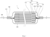
FIG. 1 is a cross-sectional view of a secondary battery according to a first embodiment of the present invention. -
FIG. 2 is a partially enlarged view ofFIG. 1 . -
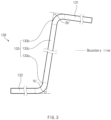
FIG. 3 is a side view illustrating an electrode tab of the secondary battery according to the first embodiment of the present invention. -
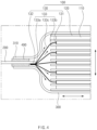
FIG. 4 is a cross-sectional view illustrating a state in which an electrode assembly of the secondary battery is deformed according to the first embodiment of the present invention. -
FIG. 5 is a flowchart illustrating a method for manufacturing a second battery according to a second embodiment of the present invention. -
FIG. 6 is a cross-sectional view illustrating a process (a) in the method for manufacturing the second battery according to the second embodiment of the present invention. -
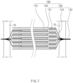
FIG. 7 is a cross-sectional view illustrating a process (b) in the method for manufacturing the second battery according to the second embodiment of the present invention. -
FIG. 8 is a side view of an electrode tab that is bent in the process (b). -
FIG. 9 is a cross-sectional view illustrating processes (b) and (d) in the method for manufacturing the second battery according to the second embodiment of the present invention. -
FIG. 10 is a cross-sectional view illustrating a process (e) in the method for manufacturing the second battery according to the second embodiment of the present invention. -
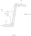
FIG. 11 is a side view of an electrode tab that is deformed in the process (e). -
FIG. 12 is a cross-sectional view illustrating a process (f) in the method for manufacturing the second battery according to the second embodiment of the present invention. -
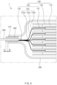
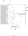
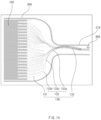
FIGS. 13 to 16 are photographed images illustrating an experimental example of the present invention. - Hereinafter, embodiments of the present invention will be described in detail with reference to the accompanying drawings in such a manner that the technical idea of the present invention may easily be carried out by a person with ordinary skill in the art to which the invention pertains. The present invention may, however, be embodied in different forms and should not be construed as limited to the embodiments set forth herein. In the drawings, anything unnecessary for describing the present invention will be omitted for clarity, and also like reference numerals in the drawings denote like elements.
- As illustrated in
FIGS. 1 to 4 , asecondary battery 1 according to a first embodiment of the present invention comprises anelectrode assembly 100 provided with a plurality of electrode tabs, anelectrode lead 200 coupled to the plurality of electrode tabs, apouch 300 accommodating theelectrode assembly 100 in a state in which a front end of theelectrode lead 200 is withdrawn to the outside, and anelectrode film 400 provided on theelectrode lead 200 disposed on an sealingpart 310 of thepouch 300. - The
electrode assembly 100 comprises a plurality ofelectrodes 110, aseparator 120 disposed between the plurality ofelectrodes 110, and a plurality ofelectrode tabs 130 respectively connected to the plurality ofelectrodes 110. - Here, the plurality of
electrodes 110 may be a positive electrode and a negative electrode, and the plurality ofelectrode tabs 130 may be a positive electrode tab connected to the positive electrode and a negative electrode tab connected to the negative electrode. - The
electrode assembly 100 having such a configuration has a structure in which the plurality ofelectrodes 110 are stacked vertically with theseparator 120 therebetween. In this case, the plurality ofelectrode tabs 130 are connected to the plurality ofelectrodes 110 in the same direction. For example, the plurality of positive electrode tabs are arranged to face a left direction when viewed inFIG. 1 , and the plurality of negative electrode tabs are arranged to face a right direction as viewed inFIG. 1 . - The plurality of
electrode tabs 130 comprise aconnection part 131 connected to each of the plurality ofelectrodes 110 and acoupling part 132 that is welded in a state of being combined into a single mass and is coupled to theelectrode lead 200. - The
electrode lead 200 is configured to connect the electrode assembly to an external device and is coupled to thecoupling part 132 of theelectrode tab 130. - The
pouch 300 is configured to accommodate the electrode assembly in a state in which the front end of theelectrode lead 200 is withdrawn to the outside. That is, thepouch 300 comprises an accommodating part accommodating theelectrode assembly 100 and a sealingpart 310 sealing the accommodating part. - The
pouch 300 further comprises alead film 400 for improving sealing force between the sealingpart 310 and theelectrode lead 200. - The
lead film 400 has a structure surrounding an outer circumferential surface of theelectrode lead 200 disposed on the sealingpart 310. That is, thelead film 400 may be bonded to the sealingpart 310 when the sealingpart 310 is thermally fused to improve the sealing force between the electrode lead and the sealing part. - The
secondary battery 1 according to the first embodiment of the present invention has a structure, in which even if the electrode assembly is swelled to increase in thickness or length, disconnection of theelectrode tab 130 is prevented. - That is, in the
secondary battery 1 according to the first embodiment of the present invention, theelectrode tab 130 may be provided in a bent state to secure a margin. Thus, when theelectrode assembly 100 is swelled, thebent electrode tab 130 may be unfolded to be flat, and thus, the length of theelectrode tab 130 may increase to prevent theelectrode tab 130 from being disconnected. - For example, the plurality of
electrode tabs 130 further comprise abent part 133 provided between theconnection part 131 and thecoupling part 132. - The
bent part 133 comprises a firstbent surface 133a connected to thecoupling part 132 and bent at a first-b angle 1b° along a thickness direction (approximately '' shape) of the
electrode assembly 100, a secondbent surface 133b connected to theconnection part 131 and bent at a second-b angle 2b° along a direction (approximately '' shape) parallel to a longitudinal direction of the
electrode assembly 100, and aconnection surface 133c connecting the firstbent surface 133a to the secondbent surface 133b. - As illustrated in
FIGS. 3 ,8 , and11 , a boundary line (---) is drawn to distinguish positions of the firstbent surface 133a, the secondbent surface 133b, and the connectingsurface 133c from each other. - Here, the first-
b angle 1b° is greater than 90° when viewed with respect to theconnection part 131. Thus, even when the electrode tab is pressed, thebent part 133 may be induced to be folded in a direction in which thebent part 133 does not face the electrode assembly, and as a result, the electrode may be prevented from being in contact with an electrode having a polarity different from that of the electrode tab. - In addition, the second-b angle 2b° is greater than 90° when viewed with respect to the
coupling part 132. Thus, even when theelectrode tab 130 is compressed in the thickness direction of the electrode assembly, thebent part 133 may be prevented from being folded in a direction in which thebent part 133 faces the electrode assembly, thereby preventing the electrode tab from being in contact with an electrode having a different polarity. - The first-
b angle 1b° may be greater than the second-b angle 2b°. That is, the second-b angle 2b° is formed to be less than the first-b angle 1b° to minimize the space between the electrode tab and the electrode assembly, and the first-b angle 1b° is formed to be greater than the second-b angle 2b° to allow the electrode lead and the electrode assembly to be largely spaced apart from each other. In addition, the first-b angle 1b° may be formed to be greater than the second-b angle 2b° to significantly secure a margin between the electrode tab and the pouch. - Referring to
FIG. 4 , in the plurality ofelectrode tabs 130 having such the structure, when theelectrode assembly 100 is swelled, a thickness or length of theelectrode assembly 100 may increase, and thus, the first and secondbent surfaces bent part 133 may be unfolded to prevent theelectrode tab 130 from being disconnected. That is, since theelectrode tab 130 has the bent shape, the margin may be secured to prevent theelectrode tab 130 from being disconnected. - Particularly, each of the plurality of
electrode tabs 130 may be made of a metal material having restoring force, and thus, when theelectrode assembly 100 returns to its original shape, thebent part 133 may also return to its original shape, and as a result, efficiency in reuse may be improved. - Therefore, since the
electrode assembly 100 comprises theelectrode tab 130 having the secured margin, even if the electrode assembly is swelled, the disconnection of theelectrode tab 130 may be prevented to improve the safety. - The first
bent surface 133a or the secondbent surface 133b is formed as a bent surface. Thus, it is possible to prevent the first and secondbent surfaces 133b from being folded at a right angle due to an external impact. Particularly, when the swelling occurs in theelectrode assembly 100, theelectrode assembly 100 may be unfolded more quickly to significantly prevent theelectrode tab 130 from being disconnected. - A distance β between an end of the separator and an end of the
coupling part 132, which face each other, in theelectrode assembly 100 is 2.0 mm to 4.5 mm, preferably 3.5 mm. That is, when theelectrode tab 130 is bent, the distance β between the end of theseparator 120 and the end of thecoupling part 132 is close to 2.0 mm to 4.5 mm. Thus, the secondary battery may be designed to be more compact in side. Here, when the distance between the end of theseparator 120 and the end of thecoupling part 132 is 2.0 mm or less, theelectrode tab 130 may be in contact with the electrode having the different polarity or theelectrode lead 200 having the different polarity to cause short circuit. When the distance between the end of theseparator 120 and the end of thecoupling part 132 is 4.5 mm or more, the secondary battery may unnecessarily increase in size. - When viewed in the longitudinal direction of the
electrode assembly 100, a distance α from one end to the other end of theconnection surface 133c to which each of the firstbent surface 133a and the secondbent surface 133b is connected is 0.5 mm to 2.0mm, preferably 1.0 mm. Accordingly, the length of the secondary battery may be minimized, and also, the margin of theelectrode tab 130 may be stably secured. Here, if the distance α from one end to the other end of theconnection surface 133c is 0.5 mm or less, there is a problem in that theelectrode tab 130 and theelectrode assembly 100 are in contact with each other, and if the distance α is 2.0 mm or more, there is a problem in that the secondary battery largely increases in length to deteriorate a product quality. - Referring to
FIG. 3 , the first-b angle 1b° of the firstbent surface 133a is inclined to be bent at 100° to 120°, preferable 109° to 116° in the thickness direction of theelectrode assembly 100 with respect to thecoupling part 132, and the second-b angle 2b° of the secondbent surface 133b is inclined to be bent at 94° to 104°, preferably 98° to 100° with respect to theconnection part 131. Thus, since each of the first and secondbent surfaces bent part 133 may maximally secure the margin of theelectrode tab 130 without damaging the pouch or separator. - Therefore, since the
secondary battery 1 according to the first embodiment of the present invention comprises theelectrode tab 130 having the first and second bent surfaces, theelectrode tab 130 may be prevented from being disconnected to improve the safety. - Hereinafter, a method for manufacturing the secondary battery according to the second embodiment of the present invention will be described.
- As illustrated in
FIGS. 5 to 12 , a method for manufacturing a secondary battery according to a second embodiment of the present invention comprises an electrode assembly manufacturing process (a), a combination process (b), a coupling process (c), an attachment process (d), a pushing process (e), and a sealing process (f). - In the process (a), as illustrated in
FIG. 6 , anelectrode 110 provided with anelectrode tab 130 is provided in plurality. Next, a plurality ofelectrodes 110 and a plurality ofseparators 120 are alternately disposed to manufacture anelectrode assembly 100. Here, theelectrode tabs 130 provided on the plurality ofelectrodes 110 are disposed to face the same direction. - In the process (b), as illustrated in
FIG. 7 , sides of the plurality ofelectrode tabs 130 are compressed using a pair of compression blocks 10 to combine front ends of theelectrode tabs 130 into a single mass. - Here, the sides of the plurality of electrode tabs are bent at a first-a angle 1a° in a thickness direction of the
electrode assembly 100 to form a firstbent surface 133a, and other ends are bent at a second-aangle 2a° in the thickness of theelectrode assembly 100 to form a secondbent surface 133b. Here, aconnection surface 133c is formed between the firstbent surface 133a and the secondbent surface 133b. - In summary, as illustrated in
FIG. 8 , theelectrode tab 130 comprises aconnection part 131 connected to an electrode, acoupling part 132 combined into a mass and coupled to anelectrode lead 200, and abent part 133 provided between theconnection part 131 and thecoupling part 132. Also, thebent part 133 comprises a firstbent surface 133a connected to thecoupling part 132 and bent at the first-a angle 1a°, a secondbent surface 133b connected to theconnection part 131 and bent at the second-aangle 2a°, and aconnection surface 133c connecting the firstbent surface 133a to the secondbent surface 133b. - Here, edges of the pair of compression blocks 10 are formed as curved surface, and thus, the first
bent surface 133a compressed by the pair of compression blocks 10 is formed as a curved surface. - The first-a angle 1a° of the first
bent surface 133a is inclined to be bent at 130° to 150°, preferable 148° in the thickness direction of theelectrode assembly 100 with respect to thecoupling part 132, and the second-aangle 2a° of the secondbent surface 133b is inclined to be bent at 94° to 104°, preferably 99° with respect to theconnection part 131. - In the process (c), as illustrated in
FIG. 9 , the front ends of theelectrode tabs 130 combined into the single mass are welded to form thecoupling part 132, and theelectrode lead 200 is coupled to thecoupling part 132. - After the process (c), when viewed in a longitudinal direction of the electrode assembly, a distance α from one end to the other end of the
connection surface 133c to which each of the firstbent surface 133a and the secondbent surface 133b is connected is 2.0 mm to 3.0mm, preferably 2.0 mm. That is, the distance α from one end to the other end of theconnection surface 133c is secured so that thebent part 133 is pressed. - In the process (d), the electrode assembly is accommodated in a
pouch 300 in a state in which a front end of theelectrode lead 200 is withdrawn to the outside, and then, anelectrode film 400 is attached to theelectrode lead 200 disposed on a sealingpart 310 of thepouch 300. Here, thelead film 400 is attached to be withdrawn further by a first length B to the outside of the sealingpart 310 of thepouch 300. - That is, referring to
FIG. 9 , thelead film 400 is withdrawn by a length A to the outside of the sealingpart 310, and in the present application, thelead film 400 is withdrawn further by the first length B to the outside of the sealing part of thepouch 300. - Here, the first length B may be 1 mm to 2 mm, preferably 1 mm.
- In the process (e), as illustrated in
FIG. 10 , thelead film 400 is pushed to be inserted by the first length B into thepouch 300 with respect to the sealingpart 310 of thepouch 300. Thus, theelectrode lead 200 is inserted by the first length B into thepouch 300 by thelead film 400, and thebent part 133 is deformed while being pressed by theelectrode lead 200 in a direction of theelectrode assembly 100. Here, a first-a angle of the firstbent surface 133a is adjusted to be reduced to a first-b angle, and a second-a angle of the secondbent surface 133b is adjusted to be reduced to a second-b angle. Here, the first-b angle of the firstbent surface 133a is connected to the coupling part that is combined into the single mass so as to be largely adjusted in angle, and the second-b angle of the secondbent surface 133b is connected to the plurality of connection parts so as to be adjusted small in angle or so as not to be adjusted in angle. Thus, since the first-b angle is largely changed compared to the first-a angle, the first-b angle is greater than the second-b angle. - Here, the
lead film 400 and the sealingpart 310 are separated from each other without being sealed. - Here, the first-
b angle 1b° of the firstbent surface 133a is inclined to be bent at 100° to 120°, preferably 109° to 116° in the thickness direction of theelectrode assembly 100 with respect to thecoupling part 132 and also inclined to be optimally bent at 111°. The second-b angle 2b° of the secondbent surface 133b is 94° to 104°, preferably 98° to 100°, and optimally, 99° with respect to theconnection part 131. - After the process (e), a distance between an end of the
separator 120 and an end of thecoupling part 132, which face each other, is 2.0 mm to 4.5 mm, preferably 3.5 mm. - That is, before the process (e), the distance between the end of the
separator 120 and the end of thecoupling part 132, which face each other, is 4.5 mm, and after the process (e), the distance between the end of theseparator 120 and the end of thecoupling part 132 is 3.5 mm. - In addition, after the process (e), when viewed in the longitudinal direction of the electrode assembly, the distance from one end of the bent surface, to which the first bent surface is connected, to the other end of the bent surface, to which the second
bent surface 133b is connected, is 0.5 mm to 2.0 mm, preferably 1.0 mm. Thus, a length of the secondary battery in the longitudinal direction may be minimized, and as a result, the secondary battery may increase in size. - In the process (f), the sealing
part 310 of thepouch 300 is sealed using asealing block 20. Thus, theelectrode assembly 100 is accommodated in thepouch 300 so as to be sealed. - When the above processes are completed, a finished
secondary battery 1 may be manufactured. - A process of inspecting whether the first-b angle of the first
bent surface 133a and the second-b angle of the secondbent surface 133b are within a preset angle range is further performed between the process (e) and the process (f). - In the process (e1), the
secondary battery 1 is vision-photographed, an image of the electrode assembly is output from the photographed image, the first-b angle of the firstbent surface 133a and the second-b angle of the secondbent surface 133b are measured from the photographed output image of the electrode assembly, and the first-b angle of the firstbent surface 133a and the second-b angle of the secondbent surface 133b, which are measured, are compared to the preset angle to inspect whether detects occur. - Here, the preset angle range of the first angle is 109° to 116°, and the preset angle range of the second angle is 94° to 104°.
- Thus, in the process (e1), the bending state of the
electrode tab 130 may be inspected. - In the process (e1), when viewed in a longitudinal direction of the electrode assembly, whether a distance α from one end to the other end of the
connection surface 133c to which each of the firstbent surface 133a and the secondbent surface 133b is connected is 0.5mm to 2.0mm, preferably 2.0 mm is further inspected. - Therefore, in a method for manufacturing the secondary battery according to the second embodiment of the present invention, a
secondary battery 1 having a secured margin may be manufactured. - In the method for manufacturing the secondary battery according to the second embodiment of the present application, four secondary batteries manufactured up to the attachment process (d) are prepared. The four secondary batteries have the same structure and are referred to as first to fourth experimental pieces.
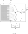
- In Experimental Example 1, the first experimental piece before the pushing process (e) is photographed. As a result, a photographic image as illustrated in
FIG. 13 may be obtained. - In Experimental Example 2, an
electrode lead 400 of the second experimental piece is pushed by 0.5 mm in the pushing process (e), and then, the second experimental piece is photographed. As a result, a photographic image as illustrated inFIG. 14 may be obtained. That is, it is confirmed that the bent angle of theelectrode tab 130 is changed in the second experimental piece rather than in the first experimental piece, and a phenomenon in which a gap occurs between the electrode and the separator does not occur. - In Experimental Example 3, an
electrode lead 400 of the third experimental piece is pushed by 1.0 mm in the pushing process (e), and then, the third experimental piece is photographed. As a result, a photographic image as illustrated inFIG. 15 may be obtained. That is, it is confirmed that the bent angle of theelectrode tab 130 is changed in the third experimental piece rather than in the second experimental piece, and a phenomenon, in which a gap between the electrode and the separator is widened, does not occur. - In Experimental Example 4, an
electrode lead 400 of the fourth experimental piece is pushed by 1.2 mm in the pushing process (e), and then, the fourth experimental piece is photographed. As a result, a photographic image as illustrated inFIG. 16 may be obtained. That is, it is seen that the bending angle of theelectrode tab 130 is significantly changed in the fourth experimental piece rather than in the third experimental piece. However, it is seen that defects, in which a gap between the electrode and the separator is widened, occur. - Therefore, as the results of the above experiments, in order to prevent the defects from occurring in the pushing process (e), the
lead film 400 has to be pushed by 0.5 mm to 1.5 mm, preferably by 1.0 mm, and when the pushing excesses the above-described values, defects, in which the gap between the electrode and the separator is widened, occur. - Accordingly, the scope of the present invention is defined by the appended claims more than the foregoing description and the exemplary embodiments described therein. Various modifications made within the meaning of an equivalent of the claims of the invention and within the claims are to be regarded to be in the scope of the present invention.
-
- 1:
- Secondary battery
- 100:
- Electrode assembly
- 110:
- Electrode
- 120:
- Separator
- 130:
- Electrode tab
- 131:
- Connection part
- 132:
- Coupling part
- 133:
- Bent part
- 133a:
- First bent surface
- 133b:
- Second bent surface
- 133c:
- Connection surface
- 200:
- Electrode lead
- 300:
- Pouch
- 400:
- Lead film
Claims (15)
- A secondary battery comprising:an electrode assembly provided with a plurality of electrodes, a separator interposed between the plurality of electrodes, and a plurality of electrode tabs respectively connected to the plurality of electrodes;an electrode lead coupled to the plurality of electrode tabs; anda pouch configured to accommodate the electrode assembly in a state in which a front end of the electrode lead is withdrawn to the outside,wherein the plurality of electrode tabs comprise a connection part connected to the plurality of electrodes, a coupling part coupled to the electrode lead in a state of being combined into a mass, and a bent part provided between the connection part and the coupling part, andthe bent part comprises a first bent surface connected to the coupling part and bent at a first-b angle, a second bent surface connected to the connection part and bent at a second-b angle, and a connection surface configured to connect the first bent surface to the second bent surface,wherein the first-b angle is greater than the second-b angle.
- The secondary battery of claim 1, wherein the first-b angle of the first bent surface is 100° to 120° with respect to the coupling part.
- The secondary battery of claim 2, wherein the first-b angle of the first bent surface is 109° to 116° with respect to the coupling part.
- The secondary battery of claim 1, wherein the second-b angle of the second bent surface is 94° to 104° with respect to the connection part.
- The secondary battery of claim 4, wherein the second-b angle of the second bent surface is 98° to 100° with respect to the connection part.
- The secondary battery of claim 1, wherein, when viewed in a longitudinal direction of the electrode assembly, a distance (α) from one end to the other end of the connection surface to which each of the first bent surface and the second bent surface is connected is 0.5 mm to 2.0 mm.
- The secondary battery of claim 1, wherein, when viewed in a longitudinal direction of the electrode assembly, a distance (β) from an end of the separator to an end of the coupling part, which face each other, is 2.0 mm to 4.5 mm.
- A method for manufacturing a secondary battery, the method comprising:a process (a) of preparing a plurality of electrodes provided with electrode tabs and alternately disposing a plurality of electrodes and a plurality of separators to manufacture an electrode assembly;a process (b) of bending the plurality of electrode tabs to be combined, wherein the bent electrode tab is provided with a connection part connected to each of the electrodes, a coupling part which is combined into a mass and to which an electrode lead is coupled, and a bent part provided between the connection part and the coupling part, and the bent part is provided with a first bent surface coupled to the coupling part and bent at a first-a angle, a second bent surface connected to the connection part and bent at a second-a angle, and a connection surface connecting the first bent surface to the second bent surface;a process (c) of coupling the electrode lead to the coupling part of the electrode tab;a process (d) of accommodating the electrode assembly in a pouch in a state in which a front end of the electrode lead is withdrawn to the outside and then attaching an electrode film to the electrode lead disposed on the sealing part of the pouch;a process (e), in which, when the lead film is pushed by a first length into the pouch, the electrode lead is inserted by the first length into the pouch by the lead film, the fist-a angle of the first bent surface is adjusted to be reduced to a first-b angle while pushing the bent part by the electrode lead, and the second-a angle of the second bent surface is adjusted to be reduced to a second-b angle; and a process (f) of sealing a sealing part (310) of the pouch on which the lead film is disposed,wherein the first-b angle is greater than the second-b angle.
- The method of claim 8, wherein, in the process (e), the first-b angle of the first bent surface is 100° to 120° with respect to the coupling part.
- The method of claim 8, wherein, in the process (e), wherein the second-b angle of the second bent surface is 94° to 104° with respect to the connection part.
- The method of claim 8, wherein, in the process (d), when the lead film is attached to the electrode lead, the lead film is attached to be withdrawn further by the first length to the outside of the pouch, andin the process (e), the lead film is pushed by the first length into the pouch,wherein the first length is 0.5 mm to 1.5 mm.
- The method of claim 8, wherein, in the process (e), when viewed in a longitudinal direction of the electrode assembly, a distance (α) from one end to the other end of the connection surface to which each of the first bent surface and the second bent surface is connected is 0.5 mm to 2.0 mm.
- The method of claim 8, wherein, when the process (e) is completed, a distance (β) between an end of the separator and an end of the coupling part, which face each other, is 2.0 mm to 4.5 mm.
- The method of claim 8, wherein a process of inspecting whether the first-b angle of the first bent surface and the second-b angle of the second bent surface are within a preset angle range is further performed between the process (e) and the process (f).
- The method of claim 8, wherein, in the process (e1), when viewed in a longitudinal direction of the electrode assembly, a distance (α) from one end to the other end of the connection surface to which each of the first bent surface and the second bent surface is connected is 0.5 mm to 2.0 mm.
Applications Claiming Priority (3)
| Application Number | Priority Date | Filing Date | Title |
|---|---|---|---|
| KR20200117212 | 2020-09-11 | ||
| KR1020210120034A KR20220034684A (en) | 2020-09-11 | 2021-09-08 | Secondary battery and manufacturing method thereof |
| PCT/KR2021/012356 WO2022055303A1 (en) | 2020-09-11 | 2021-09-10 | Secondary battery and manufacturing method therefor |
Publications (2)
| Publication Number | Publication Date |
|---|---|
| EP4175050A1 true EP4175050A1 (en) | 2023-05-03 |
| EP4175050A4 EP4175050A4 (en) | 2024-08-28 |
Family
ID=80632043
Family Applications (1)
| Application Number | Title | Priority Date | Filing Date |
|---|---|---|---|
| EP21867168.3A Pending EP4175050A4 (en) | 2020-09-11 | 2021-09-10 | SECONDARY BATTERY AND MANUFACTURING METHODS THEREFOR |
Country Status (5)
| Country | Link |
|---|---|
| US (1) | US20230275330A1 (en) |
| EP (1) | EP4175050A4 (en) |
| JP (1) | JP7558609B2 (en) |
| CN (1) | CN116134677A (en) |
| WO (1) | WO2022055303A1 (en) |
Families Citing this family (1)
| Publication number | Priority date | Publication date | Assignee | Title |
|---|---|---|---|---|
| CN114614210B (en) * | 2022-03-18 | 2024-02-20 | 东莞新能安科技有限公司 | Electrochemical devices, battery modules and electronic equipment |
Family Cites Families (14)
| Publication number | Priority date | Publication date | Assignee | Title |
|---|---|---|---|---|
| EP2002495B1 (en) * | 2006-04-03 | 2015-09-09 | LG Chem, Ltd. | Lithium secondary battery improved safety and capacity |
| JP2011081925A (en) * | 2009-10-02 | 2011-04-21 | Sumitomo Electric Ind Ltd | Nonaqueous solid electrolyte battery |
| JP2013171618A (en) * | 2012-02-17 | 2013-09-02 | Sanyo Electric Co Ltd | Laminate outer body battery |
| WO2014050988A1 (en) * | 2012-09-27 | 2014-04-03 | Necエナジーデバイス株式会社 | Lithium ion secondary battery and method for manufacturing same |
| JP2014229435A (en) * | 2013-05-21 | 2014-12-08 | 日産自動車株式会社 | Stacked battery |
| CN107408659B (en) * | 2014-10-10 | 2020-11-13 | 株式会社Lg化学 | Electrode assembly and method of making the same |
| JP6680881B2 (en) * | 2016-02-11 | 2020-04-15 | エルジー・ケム・リミテッド | Battery module |
| KR102119535B1 (en) * | 2017-01-18 | 2020-06-05 | 주식회사 엘지화학 | Battery Cell Comprising Electrode Lead Facing Outer Surface of Electrode Assembly |
| JP2018181447A (en) * | 2017-04-04 | 2018-11-15 | マクセルホールディングス株式会社 | Electrochemical element |
| KR102285642B1 (en) * | 2017-04-28 | 2021-08-04 | 주식회사 엘지에너지솔루션 | Battery Cell Comprising Electrode Lead Facing Outer Surface of Electrode Assembly |
| US10673028B2 (en) * | 2017-09-28 | 2020-06-02 | Maxwell Holdings, Ltd. | Electrochemical element |
| JP7109233B2 (en) * | 2018-03-30 | 2022-07-29 | 株式会社エンビジョンAescジャパン | Electrochemical device manufacturing method |
| KR102320342B1 (en) * | 2018-05-29 | 2021-11-03 | 주식회사 엘지에너지솔루션 | Battery module |
| KR102517098B1 (en) * | 2018-05-29 | 2023-04-03 | 주식회사 엘지에너지솔루션 | Battery module |
-
2021
- 2021-09-10 EP EP21867168.3A patent/EP4175050A4/en active Pending
- 2021-09-10 WO PCT/KR2021/012356 patent/WO2022055303A1/en not_active Ceased
- 2021-09-10 CN CN202180059677.0A patent/CN116134677A/en active Pending
- 2021-09-10 US US18/018,200 patent/US20230275330A1/en active Pending
- 2021-09-10 JP JP2022572784A patent/JP7558609B2/en active Active
Also Published As
| Publication number | Publication date |
|---|---|
| CN116134677A (en) | 2023-05-16 |
| WO2022055303A1 (en) | 2022-03-17 |
| JP2023528792A (en) | 2023-07-06 |
| US20230275330A1 (en) | 2023-08-31 |
| JP7558609B2 (en) | 2024-10-01 |
| EP4175050A4 (en) | 2024-08-28 |
Similar Documents
| Publication | Publication Date | Title |
|---|---|---|
| EP3699974B1 (en) | Method for manufacturing secondary battery and pouch for secondary battery | |
| US10230129B2 (en) | Secondary battery having a clamping device and method for manufacturing same | |
| EP3346520A1 (en) | Battery cell and method for manufacturing same | |
| US10532423B2 (en) | Battery pack and method for manufacturing the same | |
| EP3637492A1 (en) | Pouch-type secondary battery sealing block for preventing cracks, pouch-type battery case manufactured by using same, and sealing method for pouch-type battery case | |
| CN111373589B (en) | Electrode assembly having improved safety in use by outermost electrode structure and current collector material, and lithium ion secondary battery having the same | |
| CN105474428A (en) | Prismatic battery cells with a battery case made of two or more components | |
| CN118402130A (en) | Electrode joint welding device, electrode joint welding method and electrode assembly | |
| KR20190027528A (en) | Pouch type secondary battery | |
| EP4175050A1 (en) | Secondary battery and manufacturing method therefor | |
| JP7515205B2 (en) | Enclosure material, method of forming a pattern on the enclosure material, and method of producing a battery including the enclosure material | |
| US8920964B2 (en) | Rechargeable battery | |
| KR101925582B1 (en) | Rechargeable battery and case for battery | |
| KR20160026259A (en) | Method for Manufacturing Secondary Battery | |
| CN115398723B (en) | Button secondary battery and method for manufacturing same | |
| CN110571364A (en) | Pouch type secondary battery and manufacturing method thereof | |
| CN114846678A (en) | Button type secondary battery and method for manufacturing the same | |
| US7687196B2 (en) | Prismatic battery and method for manufacturing the same | |
| KR20220034684A (en) | Secondary battery and manufacturing method thereof | |
| EP4270611A1 (en) | Exterior material and battery using exterior material | |
| US20230170559A1 (en) | Button-type secondary battery and method for manufacturing the same | |
| CN115995644A (en) | Square battery and method for manufacturing square battery | |
| CN116018717B (en) | The bag for secondary batteries and its manufacturing method, as well as the method for manufacturing secondary batteries. | |
| CN115668596A (en) | Exterior material, method of forming pattern on exterior material, and method of manufacturing battery including exterior material | |
| JP7475767B2 (en) | Pouch-type secondary battery and method for manufacturing the same |
Legal Events
| Date | Code | Title | Description |
|---|---|---|---|
| STAA | Information on the status of an ep patent application or granted ep patent |
Free format text: STATUS: THE INTERNATIONAL PUBLICATION HAS BEEN MADE |
|
| PUAI | Public reference made under article 153(3) epc to a published international application that has entered the european phase |
Free format text: ORIGINAL CODE: 0009012 |
|
| STAA | Information on the status of an ep patent application or granted ep patent |
Free format text: STATUS: REQUEST FOR EXAMINATION WAS MADE |
|
| 17P | Request for examination filed |
Effective date: 20230127 |
|
| AK | Designated contracting states |
Kind code of ref document: A1 Designated state(s): AL AT BE BG CH CY CZ DE DK EE ES FI FR GB GR HR HU IE IS IT LI LT LU LV MC MK MT NL NO PL PT RO RS SE SI SK SM TR |
|
| DAV | Request for validation of the european patent (deleted) | ||
| DAX | Request for extension of the european patent (deleted) | ||
| A4 | Supplementary search report drawn up and despatched |
Effective date: 20240726 |
|
| RIC1 | Information provided on ipc code assigned before grant |
Ipc: H01M 50/116 20210101ALI20240722BHEP Ipc: H01M 50/183 20210101ALI20240722BHEP Ipc: H01M 50/172 20210101ALI20240722BHEP Ipc: H01M 50/543 20210101ALI20240722BHEP Ipc: H01M 50/586 20210101ALI20240722BHEP Ipc: H01M 10/04 20060101ALI20240722BHEP Ipc: H01M 50/105 20210101ALI20240722BHEP Ipc: H01M 50/54 20210101ALI20240722BHEP Ipc: H01M 50/531 20210101AFI20240722BHEP |
|
| STAA | Information on the status of an ep patent application or granted ep patent |
Free format text: STATUS: EXAMINATION IS IN PROGRESS |
|
| 17Q | First examination report despatched |
Effective date: 20250304 |