EP4175049A1 - Pole piece, and electrode assembly and battery using same - Google Patents
Pole piece, and electrode assembly and battery using same Download PDFInfo
- Publication number
- EP4175049A1 EP4175049A1 EP20943578.3A EP20943578A EP4175049A1 EP 4175049 A1 EP4175049 A1 EP 4175049A1 EP 20943578 A EP20943578 A EP 20943578A EP 4175049 A1 EP4175049 A1 EP 4175049A1
- Authority
- EP
- European Patent Office
- Prior art keywords
- electrode plate
- adhesive layer
- disposed
- electrode assembly
- electrode
- Prior art date
- Legal status (The legal status is an assumption and is not a legal conclusion. Google has not performed a legal analysis and makes no representation as to the accuracy of the status listed.)
- Pending
Links
Images



Classifications
-
- H—ELECTRICITY
- H01—ELECTRIC ELEMENTS
- H01M—PROCESSES OR MEANS, e.g. BATTERIES, FOR THE DIRECT CONVERSION OF CHEMICAL ENERGY INTO ELECTRICAL ENERGY
- H01M10/00—Secondary cells; Manufacture thereof
- H01M10/04—Construction or manufacture in general
- H01M10/0413—Large-sized flat cells or batteries for motive or stationary systems with plate-like electrodes
-
- H—ELECTRICITY
- H01—ELECTRIC ELEMENTS
- H01M—PROCESSES OR MEANS, e.g. BATTERIES, FOR THE DIRECT CONVERSION OF CHEMICAL ENERGY INTO ELECTRICAL ENERGY
- H01M10/00—Secondary cells; Manufacture thereof
- H01M10/05—Accumulators with non-aqueous electrolyte
- H01M10/052—Li-accumulators
-
- H—ELECTRICITY
- H01—ELECTRIC ELEMENTS
- H01M—PROCESSES OR MEANS, e.g. BATTERIES, FOR THE DIRECT CONVERSION OF CHEMICAL ENERGY INTO ELECTRICAL ENERGY
- H01M50/00—Constructional details or processes of manufacture of the non-active parts of electrochemical cells other than fuel cells, e.g. hybrid cells
- H01M50/10—Primary casings; Jackets or wrappings
- H01M50/183—Sealing members
- H01M50/184—Sealing members characterised by their shape or structure
-
- H—ELECTRICITY
- H01—ELECTRIC ELEMENTS
- H01M—PROCESSES OR MEANS, e.g. BATTERIES, FOR THE DIRECT CONVERSION OF CHEMICAL ENERGY INTO ELECTRICAL ENERGY
- H01M50/00—Constructional details or processes of manufacture of the non-active parts of electrochemical cells other than fuel cells, e.g. hybrid cells
- H01M50/10—Primary casings; Jackets or wrappings
- H01M50/183—Sealing members
- H01M50/19—Sealing members characterised by the material
- H01M50/193—Organic material
-
- H—ELECTRICITY
- H01—ELECTRIC ELEMENTS
- H01M—PROCESSES OR MEANS, e.g. BATTERIES, FOR THE DIRECT CONVERSION OF CHEMICAL ENERGY INTO ELECTRICAL ENERGY
- H01M50/00—Constructional details or processes of manufacture of the non-active parts of electrochemical cells other than fuel cells, e.g. hybrid cells
- H01M50/10—Primary casings; Jackets or wrappings
- H01M50/183—Sealing members
- H01M50/19—Sealing members characterised by the material
- H01M50/198—Sealing members characterised by the material characterised by physical properties, e.g. adhesiveness or hardness
-
- H—ELECTRICITY
- H01—ELECTRIC ELEMENTS
- H01M—PROCESSES OR MEANS, e.g. BATTERIES, FOR THE DIRECT CONVERSION OF CHEMICAL ENERGY INTO ELECTRICAL ENERGY
- H01M50/00—Constructional details or processes of manufacture of the non-active parts of electrochemical cells other than fuel cells, e.g. hybrid cells
- H01M50/50—Current conducting connections for cells or batteries
- H01M50/502—Interconnectors for connecting terminals of adjacent batteries; Interconnectors for connecting cells outside a battery casing
-
- H—ELECTRICITY
- H01—ELECTRIC ELEMENTS
- H01M—PROCESSES OR MEANS, e.g. BATTERIES, FOR THE DIRECT CONVERSION OF CHEMICAL ENERGY INTO ELECTRICAL ENERGY
- H01M10/00—Secondary cells; Manufacture thereof
- H01M10/05—Accumulators with non-aqueous electrolyte
- H01M10/058—Construction or manufacture
- H01M10/0587—Construction or manufacture of accumulators having only wound construction elements, i.e. wound positive electrodes, wound negative electrodes and wound separators
-
- H—ELECTRICITY
- H01—ELECTRIC ELEMENTS
- H01M—PROCESSES OR MEANS, e.g. BATTERIES, FOR THE DIRECT CONVERSION OF CHEMICAL ENERGY INTO ELECTRICAL ENERGY
- H01M50/00—Constructional details or processes of manufacture of the non-active parts of electrochemical cells other than fuel cells, e.g. hybrid cells
- H01M50/10—Primary casings; Jackets or wrappings
- H01M50/183—Sealing members
- H01M50/186—Sealing members characterised by the disposition of the sealing members
-
- H—ELECTRICITY
- H01—ELECTRIC ELEMENTS
- H01M—PROCESSES OR MEANS, e.g. BATTERIES, FOR THE DIRECT CONVERSION OF CHEMICAL ENERGY INTO ELECTRICAL ENERGY
- H01M50/00—Constructional details or processes of manufacture of the non-active parts of electrochemical cells other than fuel cells, e.g. hybrid cells
- H01M50/50—Current conducting connections for cells or batteries
- H01M50/531—Electrode connections inside a battery casing
- H01M50/536—Electrode connections inside a battery casing characterised by the method of fixing the leads to the electrodes, e.g. by welding
-
- Y—GENERAL TAGGING OF NEW TECHNOLOGICAL DEVELOPMENTS; GENERAL TAGGING OF CROSS-SECTIONAL TECHNOLOGIES SPANNING OVER SEVERAL SECTIONS OF THE IPC; TECHNICAL SUBJECTS COVERED BY FORMER USPC CROSS-REFERENCE ART COLLECTIONS [XRACs] AND DIGESTS
- Y02—TECHNOLOGIES OR APPLICATIONS FOR MITIGATION OR ADAPTATION AGAINST CLIMATE CHANGE
- Y02E—REDUCTION OF GREENHOUSE GAS [GHG] EMISSIONS, RELATED TO ENERGY GENERATION, TRANSMISSION OR DISTRIBUTION
- Y02E60/00—Enabling technologies; Technologies with a potential or indirect contribution to GHG emissions mitigation
- Y02E60/10—Energy storage using batteries
-
- Y—GENERAL TAGGING OF NEW TECHNOLOGICAL DEVELOPMENTS; GENERAL TAGGING OF CROSS-SECTIONAL TECHNOLOGIES SPANNING OVER SEVERAL SECTIONS OF THE IPC; TECHNICAL SUBJECTS COVERED BY FORMER USPC CROSS-REFERENCE ART COLLECTIONS [XRACs] AND DIGESTS
- Y02—TECHNOLOGIES OR APPLICATIONS FOR MITIGATION OR ADAPTATION AGAINST CLIMATE CHANGE
- Y02P—CLIMATE CHANGE MITIGATION TECHNOLOGIES IN THE PRODUCTION OR PROCESSING OF GOODS
- Y02P70/00—Climate change mitigation technologies in the production process for final industrial or consumer products
- Y02P70/50—Manufacturing or production processes characterised by the final manufactured product
Definitions
- This application relates to the field of batteries, and in particular, to an electrode plate, an electrode assembly containing the electrode plate, and a battery containing the electrode assembly.
- batteries have been widely used in various electronic products. Therefore, higher requirements are imposed on the safety of the batteries.
- a protection adhesive layer disposed on an electrode plate is usually bent together with the bending of the electrode plate. Therefore, a sealant on a tab bonded to the protection adhesive layer is pulled and warped, thereby interfering with the sealing of the electrode assembly and even causing risks of electrolyte leakage, and in turn, impairing the safety of the battery.
- An electrode plate includes an electrode plate body, a tab, a first adhesive layer, and a second adhesive layer.
- the tab includes a connecting portion and an extending portion connected to the connecting portion.
- the connecting portion overlaps and is connected to the electrode plate body.
- the extending portion protrudes from the connecting portion out of one side of the electrode plate body along a first direction.
- the first adhesive layer is disposed on the extending portion.
- the second adhesive layer includes a first part and a second part.
- the first part is bonded to a surface of the electrode plate body and covers the connecting portion.
- the second part is formed by extending the first part from a side near the first adhesive layer along the first direction and is bonded to the first adhesive layer. In a second direction perpendicular to the first direction, a width of the second part is less than a width of the first part.
- the second part is directly bonded to the first adhesive layer, or the second part is indirectly bonded to the first adhesive layer through a transition section.
- the transition section is formed by extending the second part along the first direction.
- a width of the transition section is identical to the width of the first part, or the width of the transition section is identical to the width of the second part.
- the second part in the first direction, at least partly extends beyond the electrode plate body.
- a junction between the first part and the second part is a chamfered, right-angled, acute-angled, or obtuse-angled.
- the tab includes two extending portions.
- the two extending portions are disposed on two opposite sides of the electrode plate body respectively.
- the second adhesive layer includes two second parts. The two second parts are disposed on two opposite sides of the first part respectively.
- the second part is disposed in a middle region of the first part, so that the first part extends beyond the second part at both ends along the second direction.
- the second adhesive layer further includes a third part.
- the third part is formed by extending the second part along the second direction.
- the third part is bonded to the first adhesive layer.
- the third part is at least partly disconnected from the first part.
- the third part is connected to the first part.
- a plurality of gaps are disposed at intervals at a junction between the third part and the first part to form a pre-cut-off structure at the junction.
- An electrode assembly includes a first electrode plate, a second electrode plate, and a separator located between the first electrode plate and the second electrode plate.
- the first electrode plate, the separator, and the second electrode plate are stacked and then wound to form an electrode assembly.
- the first electrode plate is the electrode plate described above.
- the electrode assembly includes a bend region. A protruding section of the first part beyond the second part is disposed in the bend region.
- the protruding section of the first part beyond the second part is disposed in the bend region, and the third part is separated from the first part.
- a battery according to this application contains the electrode assembly described above.
- the width of the second part bonded to the first adhesive layer in the second adhesive layer in the second direction is less than the width of the first part bonded to the electrode plate body in the second adhesive layer in the second direction.
- Electrode plate 100 Electrode plate body 10 Tab 20 First adhesive layer 30 Second adhesive layer 40 Connecting portion 21 Extending portion 23 First direction X First part 41 Second part 43 Second direction Y End face 430 Stepped portion 45 Stepped face 410 Third part 47 Gap 470 Electrode assembly 600 First electrode plate 601 Second electrode plate 603 Separator 605 Bend region 61 Flat region 63
- an electrode plate 100 includes an electrode plate body 10, a tab 20, a first adhesive layer 30, and a second adhesive layer 40.
- the tab 20 includes a connecting portion 21 and an extending portion 23 connected to the connecting portion 21.
- the connecting portion 21 overlaps and is connected to the electrode plate body 10.
- the extending portion 23 protrudes from the connecting portion 21 out of one side of the electrode plate body 10 along a first direction X, and is configured to be electrically connected to other electronic components.
- the first adhesive layer 30 is disposed on the extending portion 23.
- the second adhesive layer 40 includes a first part 41 and a second part 43. The first part 41 is bonded to a surface of the electrode plate body 10 and covers the connecting portion 21.
- the second part 43 is formed by extending the first part 41 from a side near the first adhesive layer 30 along the first direction X and is bonded to the first adhesive layer 30. In a second direction Y perpendicular to the first direction X, a width of the second part 43 is less than a width of the first part 41.
- the first adhesive layer 30 is thermally melted and thoroughly bonded to a sealing film when the electrode plate 100 is subsequently sealed in the sealing film to form a battery, so as to implement sealing at the tab 20.
- the second adhesive layer 40 can cover burrs at a weld between the connecting portion 21 and the electrode plate body 10, thereby reducing the risk that the burrs pierce the sealing film subsequently and other risks such as a short circuit caused by the burrs.
- the second adhesive layer 40 can further reduce the risk of a contact and short circuit between the positive electrode plate and the negative electrode plate.
- the width of the second part 43 bonded to the first adhesive layer 30 in the second adhesive layer 40 in the second direction Y is less than the width of the first part 41 bonded to the electrode plate body 10 in the second adhesive layer 40 in the second direction Y.
- the first adhesive layer 30 may be, but without being limited to, green adhesive or hot melt adhesive, and may be other adhesive materials used as a sealant.
- the thickness of the first adhesive layer 30 is not limited herein, and may be adjusted as required.
- the second adhesive layer 40 may be a bonding layer or adhesive tape.
- the adhesive tape includes a substrate layer and a bonding layer disposed on the substrate layer.
- the adhesive tape may be single-sided tape or double-sided tape.
- the thickness of the second adhesive layer 40 is enough to prevent the burrs at the weld between the connecting portion 21 and the electrode plate body 10 from piercing the second adhesive layer 40.
- the first part 41 may extend beyond an edge of the electrode plate body 10 (as shown in FIG. 2 ) and overlap the region (as shown in FIG. 3 ) of the electrode plate body 10 except the edge, or may be aligned with the edge of the electrode plate body 10 (as shown in FIG. 4 ).
- the first part 41 is aligned with the edge of the electrode plate body 10 (as shown in FIG. 4 ) or extends beyond the edge of the electrode plate body 10 (as shown in FIG. 2 ), thereby further reducing the degree to which the first part 41 interferes with the first adhesive layer 30 due to bending of the electrode plate body.
- the first part 41 extends beyond the edge of the electrode plate body 10 (as shown in FIG. 2 ), thereby further reducing the risk of a contact and short circuit between positive electrode plate and the negative electrode plate while reducing the degree to which the second adhesive layer 40 interferes with the first adhesive layer 30.
- An end face 430 of the second part 43 may be at a right angle (as shown in FIG. 2 ), acute angle, or obtuse angle to the first part 41.
- the junction between the first part 41 and the second part 43 that is, the junction between the first part 41 and the end face 430 may be chamfered or rounded.
- the junction between the first part 41 and the end face 430 is rounded, so as to reduce stress concentration at the junction between the first part 41 and the end face 430 during subsequent winding of the electrode plate 100.
- the tab 20 may include two extending portions 23.
- the two extending portions 23 are disposed on two opposite sides of the electrode plate body 10 respectively. According to an embodiment of this application, the two extending portions 23 may extend to the same connecting portion 21. According to another embodiment of this application, the two extending portions 23 may extend to the two connecting portions 21 respectively.
- the first adhesive layer 30 is disposed on each extending portion 23.
- the second adhesive layer 40 correspondingly includes two second parts 43.
- the two second parts 43 are disposed on two opposite sides of the first part 41 respectively, and are bonded to the first adhesive layers 30 on adjacent extending portions 23 respectively.
- the width of each second part 43 is less than the width of the first part 41.
- the end faces 430 of the two second parts 43 are flush with each other in the second direction Y. In some embodiments, the end faces 430 of the two second parts 43 may be not flush with each other in the second direction Y
- a structure of a stepped portion 45 may be formed between each of the two second parts 43 and the first part 41, and the two stepped portions are of the same structure.
- a structure of a stepped portion 45 may be formed between each of the two second parts 43 and the first part 41, and the two stepped portions are of different structures, as shown in FIG. 7 .
- one stepped portion 45 exists between the first part 41 and each of the second parts 43.
- two stepped portions 45 may exist between the first part 41 and each of the second parts 43.
- the two stepped portions 45 are located on two sides of the second part 43 respectively along the second direction Y, thereby facilitating the winding of the electrode plate 100.
- the widths of stepped faces 410 of the two stepped portions 45 in the second direction Y may be the same or different.
- the second adhesive layer 40 may further include a third part 47.
- the third part 47 is formed by extending the second part from the end face 430 along the second direction Y
- the third part 47 is bonded to the first adhesive layer 30, and the third part 47 is at least partly disconnected from the stepped face 410.
- the third part 47 can further reduce the risk of short circuits.
- the third part 47 is connected to the first part 41.
- a plurality of gaps 470 are disposed at intervals at a junction between the third part 47 and the first part 41 to form a pre-cut-off structure at the junction.
- the third part 47 is separated from the first part 41 under the action of a force.
- Each gap 470 may be, but without being limited to, a cross section, a circular hole, a bar hole, a square hole, a prismatic hole, or another regular or irregular hole.
- the number of the gaps 470 is set as required.
- the spacing between any two adjacent gaps 470 may also be set as required, details of which are omitted here.
- the third part 47 is fully disconnected, that is, separated, from the first part 41, thereby preventing the first part 41 from directly acting on the third part 47 and reducing the degree of interfering with the first adhesive layer 30.
- the third part 47 is disposed on at least one of the end faces 430.
- the structures between any two of the third parts 47 and an adjacent first part 41 may be identical or different.
- the electrode plate 100 is applied to an electrode assembly.
- the electrode assembly 600 includes a first electrode plate 601, a second electrode plate 603, and a separator 605 located between the first electrode plate 601 and the second electrode plate 603.
- the first electrode plate 601, the separator 605, and the second electrode plate 603 are stacked and then wound to form the electrode assembly 600.
- the electrode plate 100 serves as the first electrode plate 601.
- the electrode assembly 600 includes a bend region 61 and a flat region 63 connected to the bend region 61.
- the tab 20 is disposed in the flat region 63.
- a region corresponding to the second part 43 in the first part 41 is disposed in the flat region 63.
- a protruding section of the first part 41 beyond the second part 43 is located on a side that is of the second part 43 and that is close to the bend region 61.
- At least a part of the protruding section of the first part 41 beyond the second part 43 may be disposed in the bend region 61, as long as it is ensured that the region corresponding to the second part 43 in the first part 41 is disposed in the flat region 63, thereby reducing the degree to which the second adhesive layer 40 interferes with the first adhesive layer 30 during winding of the electrode plate 100.
- the electrode plate 100 applied to the electrode assembly 600 further includes the third part 47, if at least a part of the protruding section of the first part 41 beyond the second part 43 is disposed in the bend region 61, the third part 47 is separated from the part of the protruding section of the first part 41 beyond the second part 43, where that part is disposed in the bend region 61.
- the structures of the first adhesive layer 30 and the second adhesive layer 40 in the electrode plate 100 as well as the positional relationship between each adhesive layer and the tab or the electrode plate body is also applicable to the second electrode plate 603.
- the electrode assembly 600 is applied to an electrochemical device (not shown in the drawing).
- the electrochemical device may be, but without being limited to, a battery.
- the width of the second part 43 bonded to the first adhesive layer 30 in the second adhesive layer 40 in the second direction Y is less than the width of the first part 41 bonded to the electrode plate body 10 in the second adhesive layer 40 in the second direction Y.
Landscapes
- Chemical & Material Sciences (AREA)
- Chemical Kinetics & Catalysis (AREA)
- Electrochemistry (AREA)
- General Chemical & Material Sciences (AREA)
- Engineering & Computer Science (AREA)
- Manufacturing & Machinery (AREA)
- Connection Of Batteries Or Terminals (AREA)
- Secondary Cells (AREA)
Abstract
Description
- This application relates to the field of batteries, and in particular, to an electrode plate, an electrode assembly containing the electrode plate, and a battery containing the electrode assembly.
- By virtue of a high energy density, a high working voltage, a long cycle life, environmental friendliness, safety, and other advantages, batteries have been widely used in various electronic products. Therefore, higher requirements are imposed on the safety of the batteries. In a jelly-roll electrode assembly, especially when a tab is disposed near a bend region of the electrode assembly, a protection adhesive layer disposed on an electrode plate is usually bent together with the bending of the electrode plate. Therefore, a sealant on a tab bonded to the protection adhesive layer is pulled and warped, thereby interfering with the sealing of the electrode assembly and even causing risks of electrolyte leakage, and in turn, impairing the safety of the battery.
- In view of the foregoing situation, it is necessary to provide an electrode plate that improves safety.
- In addition, it is necessary to provide an electrode assembly containing the electrode plate, and a battery containing the electrode assembly.
- An electrode plate according to this application includes an electrode plate body, a tab, a first adhesive layer, and a second adhesive layer. The tab includes a connecting portion and an extending portion connected to the connecting portion. The connecting portion overlaps and is connected to the electrode plate body. The extending portion protrudes from the connecting portion out of one side of the electrode plate body along a first direction. The first adhesive layer is disposed on the extending portion.
- The second adhesive layer includes a first part and a second part. The first part is bonded to a surface of the electrode plate body and covers the connecting portion. The second part is formed by extending the first part from a side near the first adhesive layer along the first direction and is bonded to the first adhesive layer. In a second direction perpendicular to the first direction, a width of the second part is less than a width of the first part.
- As a technical solution of this application, the second part is directly bonded to the first adhesive layer, or the second part is indirectly bonded to the first adhesive layer through a transition section. The transition section is formed by extending the second part along the first direction.
- As a technical solution of this application, along the second direction, a width of the transition section is identical to the width of the first part, or the width of the transition section is identical to the width of the second part.
- As a technical solution of this application, in the first direction, the second part at least partly extends beyond the electrode plate body.
- As a technical solution of this application, a junction between the first part and the second part is a chamfered, right-angled, acute-angled, or obtuse-angled.
- As a technical solution of this application, the tab includes two extending portions. The two extending portions are disposed on two opposite sides of the electrode plate body respectively. The second adhesive layer includes two second parts. The two second parts are disposed on two opposite sides of the first part respectively.
- As a technical solution of this application, the second part is disposed in a middle region of the first part, so that the first part extends beyond the second part at both ends along the second direction.
- As a technical solution of this application, the second adhesive layer further includes a third part. The third part is formed by extending the second part along the second direction. The third part is bonded to the first adhesive layer. The third part is at least partly disconnected from the first part.
- As a technical solution of this application, the third part is connected to the first part. A plurality of gaps are disposed at intervals at a junction between the third part and the first part to form a pre-cut-off structure at the junction.
- An electrode assembly according to this application includes a first electrode plate, a second electrode plate, and a separator located between the first electrode plate and the second electrode plate. The first electrode plate, the separator, and the second electrode plate are stacked and then wound to form an electrode assembly. The first electrode plate is the electrode plate described above.
- As a technical solution of this application, the electrode assembly includes a bend region. A protruding section of the first part beyond the second part is disposed in the bend region.
- As a technical solution of this application, the protruding section of the first part beyond the second part is disposed in the bend region, and the third part is separated from the first part.
- A battery according to this application contains the electrode assembly described above.
- In the electrode plate, the electrode assembly containing the electrode plate, and the battery containing the electrode assembly according to this application, the width of the second part bonded to the first adhesive layer in the second adhesive layer in the second direction is less than the width of the first part bonded to the electrode plate body in the second adhesive layer in the second direction. This reduces the degree to which the second adhesive layer interferes with the first adhesive layer during winding of the electrode plate, and reduces the risk of warping the first adhesive layer when the second adhesive layer bends together with the bending of the electrode plate body, thereby reducing the impact caused to subsequent sealing of the electrode plate, reducing problems such as poor sealing or even electrolyte leakage, improving the yield rate of the subsequent sealing, the reliability, and safety.
-
-
FIG. 1 is a schematic structural diagram of an electrode plate according to an embodiment of this application; -
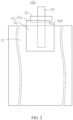
FIG. 2 is a schematic structural diagram of an electrode plate according to an embodiment of this application; -
FIG. 3 is a schematic structural diagram of an electrode plate according to an embodiment of this application; -
FIG. 4 is a schematic structural diagram of an electrode plate according to an embodiment of this application; -
FIG. 5 is a schematic structural diagram of an electrode plate according to an embodiment of this application; -
FIG. 6 is a schematic structural diagram of an electrode plate according to an embodiment of this application; -
FIG. 7 is a schematic structural diagram of an electrode plate according to an embodiment of this application; -
FIG. 8 is a schematic structural diagram of an electrode plate according to an embodiment of this application; -
FIG. 9 is a schematic structural diagram of an electrode plate according to an embodiment of this application; -
FIG. 10 is a schematic structural diagram of an electrode plate according to an embodiment of this application; -
FIG. 11 is a schematic structural diagram of an electrode assembly according to an embodiment of this application; -
FIG. 12 is a schematic structural diagram of an electrode assembly according to an embodiment of this application; and -
FIG. 13 is a schematic structural diagram of an electrode assembly according to an embodiment of this application. - Reference numerals of main components:
Electrode plate 100 Electrode plate body 10 Tab 20 First adhesive layer 30 Second adhesive layer 40 Connecting portion 21 Extending portion 23 First direction X First part 41 Second part 43 Second direction Y End face 430 Stepped portion 45 Stepped face 410 Third part 47 Gap 470 Electrode assembly 600 First electrode plate 601 Second electrode plate 603 Separator 605 Bend region 61 Flat region 63 - This application is further described below with reference to the following specific embodiments and the foregoing drawings.
- The following describes the technical solutions in the embodiments of this application clearly and thoroughly with reference to the drawings herein. Evidently, the described embodiments are merely a part of but not all of the embodiments of this application.
- Unless otherwise defined, all technical and scientific terms used herein have the same meanings as what is normally ascribed to such terms by a person skilled in the technical field of this application. The terms used in the specification of this application are merely intended to describe specific embodiments but not to limit this application.
- The following describes some embodiments of this application in detail with reference to drawings. To the extent that no conflict occurs, the following embodiments and the features in the embodiments may be combined with each other.
- Referring to
FIG. 1 , according to an embodiment of this application, anelectrode plate 100 includes anelectrode plate body 10, atab 20, a firstadhesive layer 30, and a secondadhesive layer 40. Thetab 20 includes a connectingportion 21 and an extendingportion 23 connected to the connectingportion 21. The connectingportion 21 overlaps and is connected to theelectrode plate body 10. The extendingportion 23 protrudes from the connectingportion 21 out of one side of theelectrode plate body 10 along a first direction X, and is configured to be electrically connected to other electronic components. The firstadhesive layer 30 is disposed on the extendingportion 23. The secondadhesive layer 40 includes afirst part 41 and asecond part 43. Thefirst part 41 is bonded to a surface of theelectrode plate body 10 and covers the connectingportion 21. Thesecond part 43 is formed by extending thefirst part 41 from a side near the firstadhesive layer 30 along the first direction X and is bonded to the firstadhesive layer 30. In a second direction Y perpendicular to the first direction X, a width of thesecond part 43 is less than a width of thefirst part 41. The firstadhesive layer 30 is thermally melted and thoroughly bonded to a sealing film when theelectrode plate 100 is subsequently sealed in the sealing film to form a battery, so as to implement sealing at thetab 20. When covering the connectingportion 21, the secondadhesive layer 40 can cover burrs at a weld between the connectingportion 21 and theelectrode plate body 10, thereby reducing the risk that the burrs pierce the sealing film subsequently and other risks such as a short circuit caused by the burrs. In addition, during formation of an electrode assembly or a battery, the secondadhesive layer 40 can further reduce the risk of a contact and short circuit between the positive electrode plate and the negative electrode plate. The width of thesecond part 43 bonded to the firstadhesive layer 30 in the secondadhesive layer 40 in the second direction Y is less than the width of thefirst part 41 bonded to theelectrode plate body 10 in the secondadhesive layer 40 in the second direction Y This reduces the degree to which the secondadhesive layer 40 interferes with the firstadhesive layer 30 during winding of theelectrode plate 100, and reduces the risk of warping the firstadhesive layer 30 when the secondadhesive layer 40 bends together with the bending of theelectrode plate body 10, thereby reducing the impact caused to subsequent sealing of the electrode plate, reducing problems such as poor sealing or even electrolyte leakage, improving the yield rate of the subsequent sealing, the reliability, and safety. - The first
adhesive layer 30 may be, but without being limited to, green adhesive or hot melt adhesive, and may be other adhesive materials used as a sealant. The thickness of the firstadhesive layer 30 is not limited herein, and may be adjusted as required. - The second
adhesive layer 40 may be a bonding layer or adhesive tape. The adhesive tape includes a substrate layer and a bonding layer disposed on the substrate layer. The adhesive tape may be single-sided tape or double-sided tape. - Preferably, the thickness of the second
adhesive layer 40 is enough to prevent the burrs at the weld between the connectingportion 21 and theelectrode plate body 10 from piercing the secondadhesive layer 40. - Referring to
FIG. 2 ,FIG. 3 , andFIG. 4 , thefirst part 41 may extend beyond an edge of the electrode plate body 10 (as shown inFIG. 2 ) and overlap the region (as shown inFIG. 3 ) of theelectrode plate body 10 except the edge, or may be aligned with the edge of the electrode plate body 10 (as shown inFIG. 4 ). Preferably, thefirst part 41 is aligned with the edge of the electrode plate body 10 (as shown inFIG. 4 ) or extends beyond the edge of the electrode plate body 10 (as shown inFIG. 2 ), thereby further reducing the degree to which thefirst part 41 interferes with the firstadhesive layer 30 due to bending of the electrode plate body. More preferably, thefirst part 41 extends beyond the edge of the electrode plate body 10 (as shown inFIG. 2 ), thereby further reducing the risk of a contact and short circuit between positive electrode plate and the negative electrode plate while reducing the degree to which the secondadhesive layer 40 interferes with the firstadhesive layer 30. - An
end face 430 of thesecond part 43 may be at a right angle (as shown inFIG. 2 ), acute angle, or obtuse angle to thefirst part 41. - In some embodiments, the junction between the
first part 41 and thesecond part 43, that is, the junction between thefirst part 41 and theend face 430 may be chamfered or rounded. Preferably, referring toFIG. 5 , the junction between thefirst part 41 and theend face 430 is rounded, so as to reduce stress concentration at the junction between thefirst part 41 and theend face 430 during subsequent winding of theelectrode plate 100. - In some embodiments, referring to
FIG. 6 , thetab 20 may include two extendingportions 23. The two extendingportions 23 are disposed on two opposite sides of theelectrode plate body 10 respectively. According to an embodiment of this application, the two extendingportions 23 may extend to the same connectingportion 21. According to another embodiment of this application, the two extendingportions 23 may extend to the two connectingportions 21 respectively. The firstadhesive layer 30 is disposed on each extendingportion 23. - The second
adhesive layer 40 correspondingly includes twosecond parts 43. The twosecond parts 43 are disposed on two opposite sides of thefirst part 41 respectively, and are bonded to the firstadhesive layers 30 on adjacent extendingportions 23 respectively. In the second direction Y, the width of eachsecond part 43 is less than the width of thefirst part 41. In this embodiment, the end faces 430 of the twosecond parts 43 are flush with each other in the second direction Y. In some embodiments, the end faces 430 of the twosecond parts 43 may be not flush with each other in the second direction Y - According to an embodiment of this application, a structure of a stepped
portion 45 may be formed between each of the twosecond parts 43 and thefirst part 41, and the two stepped portions are of the same structure. In some embodiments, a structure of a steppedportion 45 may be formed between each of the twosecond parts 43 and thefirst part 41, and the two stepped portions are of different structures, as shown inFIG. 7 . - Referring to
FIG. 1 , one steppedportion 45 exists between thefirst part 41 and each of thesecond parts 43. In some embodiments, referring toFIG. 8 , two steppedportions 45 may exist between thefirst part 41 and each of thesecond parts 43. The two steppedportions 45 are located on two sides of thesecond part 43 respectively along the second direction Y, thereby facilitating the winding of theelectrode plate 100. The widths of stepped faces 410 of the two steppedportions 45 in the second direction Y may be the same or different. - In some embodiments, referring to
FIG. 9 andFIG. 10 , the secondadhesive layer 40 may further include athird part 47. Thethird part 47 is formed by extending the second part from theend face 430 along the second direction Y Thethird part 47 is bonded to the firstadhesive layer 30, and thethird part 47 is at least partly disconnected from the steppedface 410. Thethird part 47 can further reduce the risk of short circuits. - As shown in 9, the
third part 47 is connected to thefirst part 41. A plurality ofgaps 470 are disposed at intervals at a junction between thethird part 47 and thefirst part 41 to form a pre-cut-off structure at the junction. During winding of theelectrode plate 100, thethird part 47 is separated from thefirst part 41 under the action of a force. - Each
gap 470 may be, but without being limited to, a cross section, a circular hole, a bar hole, a square hole, a prismatic hole, or another regular or irregular hole. The number of thegaps 470 is set as required. The spacing between any twoadjacent gaps 470 may also be set as required, details of which are omitted here. - As shown in
FIG. 10 , thethird part 47 is fully disconnected, that is, separated, from thefirst part 41, thereby preventing thefirst part 41 from directly acting on thethird part 47 and reducing the degree of interfering with the firstadhesive layer 30. - In some embodiments, when the second
adhesive layer 40 includes at least two steppedportions 45, thethird part 47 is disposed on at least one of the end faces 430. When the secondadhesive layer 40 includes at least twothird parts 47, the structures between any two of thethird parts 47 and an adjacentfirst part 41 may be identical or different. - The
electrode plate 100 is applied to an electrode assembly. Referring toFIG. 11 andFIG. 12 , according to an embodiment of this application, theelectrode assembly 600 includes afirst electrode plate 601, asecond electrode plate 603, and aseparator 605 located between thefirst electrode plate 601 and thesecond electrode plate 603. Thefirst electrode plate 601, theseparator 605, and thesecond electrode plate 603 are stacked and then wound to form theelectrode assembly 600. - In this embodiment, the
electrode plate 100 serves as thefirst electrode plate 601. - The
electrode assembly 600 includes abend region 61 and aflat region 63 connected to thebend region 61. Thetab 20 is disposed in theflat region 63. - A region corresponding to the
second part 43 in thefirst part 41 is disposed in theflat region 63. A protruding section of thefirst part 41 beyond thesecond part 43 is located on a side that is of thesecond part 43 and that is close to thebend region 61. - In some embodiments, referring to
FIG. 12 , at least a part of the protruding section of thefirst part 41 beyond thesecond part 43 may be disposed in thebend region 61, as long as it is ensured that the region corresponding to thesecond part 43 in thefirst part 41 is disposed in theflat region 63, thereby reducing the degree to which the secondadhesive layer 40 interferes with the firstadhesive layer 30 during winding of theelectrode plate 100. - In some embodiments, referring to
FIG. 13 , when theelectrode plate 100 applied to theelectrode assembly 600 further includes thethird part 47, if at least a part of the protruding section of thefirst part 41 beyond thesecond part 43 is disposed in thebend region 61, thethird part 47 is separated from the part of the protruding section of thefirst part 41 beyond thesecond part 43, where that part is disposed in thebend region 61. - In some embodiments, the structures of the first
adhesive layer 30 and the secondadhesive layer 40 in theelectrode plate 100 as well as the positional relationship between each adhesive layer and the tab or the electrode plate body is also applicable to thesecond electrode plate 603. - The
electrode assembly 600 is applied to an electrochemical device (not shown in the drawing). The electrochemical device may be, but without being limited to, a battery. - In the electrode plate, the electrode assembly containing the electrode plate, and the battery containing the electrode assembly according to this application, the width of the
second part 43 bonded to the firstadhesive layer 30 in the secondadhesive layer 40 in the second direction Y is less than the width of thefirst part 41 bonded to theelectrode plate body 10 in the secondadhesive layer 40 in the second direction Y. This reduces the degree to which the secondadhesive layer 40 interferes with the firstadhesive layer 30 during winding of theelectrode plate 100, and reduces the risk of warping the firstadhesive layer 30 when the secondadhesive layer 40 bends together with the bending of theelectrode plate body 10, thereby reducing the impact caused to subsequent sealing of the electrode plate, reducing problems such as poor sealing or even electrolyte leakage, improving the yield rate of the subsequent sealing, the reliability, and safety. - Various modifications and variations may be made by a person of ordinary skill in the art based on the technical conception hereof, and all such modifications and variations still fall within the protection scope of this application.
Claims (15)
- An electrode plate, comprising: an electrode plate body, a tab, a first adhesive layer, and a second adhesive layer, wherein the tab comprises a connecting portion and an extending portion connected to the connecting portion, the connecting portion overlaps and is connected to the electrode plate body, the extending portion protrudes from the connecting portion out of one side of the electrode plate body along a first direction, and the first adhesive layer is disposed on the extending portion, characterized in that:
the second adhesive layer comprises a first part and a second part, the first part is bonded to a surface of the electrode plate body and covers the connecting portion, the second part is formed by extending the first part from a side near the first adhesive layer along the first direction and is bonded to the first adhesive layer, and, in a second direction that is approximately perpendicular to the first direction, a width of the second part is less than a width of the first part. - The electrode plate according to claim 1, characterized in that the second part is directly bonded to the first adhesive layer, or the second part is indirectly bonded to the first adhesive layer through a transition section, wherein the transition section is formed by extending the second part along the first direction.
- The electrode plate according to claim 2, characterized in that along the second direction, a width of the transition section is identical to the width of the first part, or the width of the transition section is identical to the width of the second part.
- The electrode plate according to claim 1, characterized in that, in the first direction, the second part at least partly extends beyond the electrode plate body.
- The electrode plate according to claim 1, characterized in that a junction between the first part and the second part is chamfered.
- The electrode plate according to claim 1, characterized in that the tab comprises two extending portions, the two extending portions are disposed on two opposite sides of the electrode plate body respectively, the second adhesive layer comprises two second parts, and the two second parts are disposed on two opposite sides of the first part respectively.
- The electrode plate according to claim 1, characterized in that the second part is disposed in a middle region of the first part, so that the first part extends beyond the second part at both ends along the second direction.
- The electrode plate according to any one of claims 1 to 7, characterized in that the second adhesive layer further comprises a third part, the third part is formed by extending the second part along the second direction, the third part is bonded to the first adhesive layer, and the third part is at least partly disconnected from the first part.
- The electrode plate according to claim 8, characterized in that the third part is connected to the first part, and a plurality of gaps are disposed at intervals at a junction between the third part and the first part to form a pre-cut-off structure at the junction.
- An electrode assembly, comprising a first electrode plate, a second electrode plate, and a separator located between the first electrode plate and the second electrode plate, wherein the first electrode plate, the separator, and the second electrode plate are stacked and then wound to form an electrode assembly, characterized in that the first electrode plate is the electrode plate according to any one of claims 1 to 7.
- The electrode assembly according to claim 10, characterized in that the electrode assembly comprises a bend region, and a protruding section of the first part beyond the second part is disposed in the bend region.
- The electrode assembly according to claim 10, characterized in that the second adhesive layer further comprises a third part, the third part is formed by extending the second part along the second direction, the third part is bonded to the first adhesive layer, and the third part is at least partly disconnected from the first part.
- The electrode assembly according to claim 12, characterized in that the third part is connected to the first part, and a plurality of gaps are disposed at intervals at a junction between the third part and the first part to form a pre-cut-off structure at the junction.
- The electrode assembly according to claim 13, characterized in that the electrode assembly comprises a bend region, a protruding section of the first part beyond the second part is disposed in the bend region, and the third part is separated from the first part.
- A battery, characterized in that the battery comprises the electrode assembly according to any one of claims 10 to 14.
Applications Claiming Priority (1)
| Application Number | Priority Date | Filing Date | Title |
|---|---|---|---|
| PCT/CN2020/099584 WO2022000342A1 (en) | 2020-06-30 | 2020-06-30 | Pole piece, and electrode assembly and battery using same |
Publications (2)
| Publication Number | Publication Date |
|---|---|
| EP4175049A1 true EP4175049A1 (en) | 2023-05-03 |
| EP4175049A4 EP4175049A4 (en) | 2024-01-17 |
Family
ID=79317730
Family Applications (1)
| Application Number | Title | Priority Date | Filing Date |
|---|---|---|---|
| EP20943578.3A Pending EP4175049A4 (en) | 2020-06-30 | 2020-06-30 | POLAR PART, ELECTRODE AND BATTERY ASSEMBLY USING IT |
Country Status (4)
| Country | Link |
|---|---|
| US (1) | US20230146401A1 (en) |
| EP (1) | EP4175049A4 (en) |
| CN (1) | CN115398737B (en) |
| WO (1) | WO2022000342A1 (en) |
Families Citing this family (2)
| Publication number | Priority date | Publication date | Assignee | Title |
|---|---|---|---|---|
| CN113422099B (en) * | 2021-07-08 | 2023-04-25 | 傲普(上海)新能源有限公司 | Lithium battery pole piece rubberizing frock |
| CN114552135A (en) * | 2022-02-28 | 2022-05-27 | 上海兰钧新能源科技有限公司 | Novel tab protection structure for secondary battery, tab forming method and battery cell |
Family Cites Families (10)
| Publication number | Priority date | Publication date | Assignee | Title |
|---|---|---|---|---|
| CN201364922Y (en) * | 2009-03-23 | 2009-12-16 | 保定风帆新能源有限公司 | Lithium battery anode piece structure |
| CN202134604U (en) * | 2011-06-20 | 2012-02-01 | 曙鹏科技(深圳)有限公司 | Cell of lithium battery with flexible package and lithium battery with flexible package |
| CN202633423U (en) * | 2012-02-14 | 2012-12-26 | 东莞新能源科技有限公司 | Flexible packaging battery tab structure and its die-cutting fixture |
| JP6405856B2 (en) * | 2014-10-01 | 2018-10-17 | 住友電気工業株式会社 | Lead member and lead member manufacturing method |
| JP2016139586A (en) * | 2015-01-29 | 2016-08-04 | 株式会社豊田自動織機 | Power storage device |
| CN205609666U (en) * | 2015-12-29 | 2016-09-28 | 湖北宇电能源科技股份有限公司 | Safe lithium ion power batteries positive plate |
| CN109301149B (en) * | 2018-10-08 | 2022-09-13 | 桑顿新能源科技(长沙)有限公司 | Lithium ion battery tab and packaging method of lithium ion battery |
| CN209709077U (en) * | 2019-03-13 | 2019-11-29 | 惠州华跃科技有限公司 | A kind of aluminium-to-nickel tab |
| CN210092210U (en) * | 2019-05-28 | 2020-02-18 | 东莞新能源科技有限公司 | Battery |
| CN209786105U (en) * | 2019-06-19 | 2019-12-13 | 宁德时代新能源科技股份有限公司 | secondary battery |
-
2020
- 2020-06-30 WO PCT/CN2020/099584 patent/WO2022000342A1/en not_active Ceased
- 2020-06-30 EP EP20943578.3A patent/EP4175049A4/en active Pending
- 2020-06-30 CN CN202080099877.4A patent/CN115398737B/en active Active
-
2022
- 2022-12-30 US US18/148,572 patent/US20230146401A1/en active Pending
Also Published As
| Publication number | Publication date |
|---|---|
| US20230146401A1 (en) | 2023-05-11 |
| CN115398737B (en) | 2024-06-11 |
| CN115398737A (en) | 2022-11-25 |
| EP4175049A4 (en) | 2024-01-17 |
| WO2022000342A1 (en) | 2022-01-06 |
Similar Documents
| Publication | Publication Date | Title |
|---|---|---|
| US20230344019A1 (en) | Electrode assembly and electrochemical apparatus | |
| KR102905860B1 (en) | Batteries and electronic devices | |
| EP3588620B1 (en) | Secondary battery and electrode plate thereof | |
| EP3331062B1 (en) | Secondary battery | |
| US20230146401A1 (en) | Electrode plate, electrode assembly containing same, and battery | |
| US11245135B2 (en) | Secondary battery with insulating tapes | |
| US11024868B2 (en) | Secondary battery cell | |
| US11196131B2 (en) | Secondary battery | |
| US12142732B2 (en) | Battery cell and electrochemical device including same | |
| US12592458B2 (en) | Battery cell with overlap between insulator and connector, battery, and electronic device | |
| CN115458879A (en) | Battery cell and battery cell manufacturing method | |
| WO2025118457A1 (en) | Back-contact cell, cell string, cell module and photovoltaic system | |
| US11811075B2 (en) | Secondary battery | |
| EP4683461A1 (en) | Battery string and photovoltaic module | |
| US20240405255A1 (en) | Battery cell, battery, and electrical device | |
| CN119545921B (en) | Battery strings and photovoltaic modules | |
| KR102688739B1 (en) | Package structure and cells applicable to the package structure | |
| WO2025060935A1 (en) | Electrode sheet assembly and battery | |
| CN218731662U (en) | Pole piece, battery core and battery | |
| CN118763265A (en) | Electrochemical devices and electronic devices | |
| CN222602936U (en) | Photovoltaic panels and photovoltaic systems | |
| CN222564260U (en) | Battery piece and photovoltaic module | |
| US20250279516A1 (en) | Electrochemical apparatus, electronic device, and manufacturing method for electrochemical apparatus | |
| CN222088728U (en) | Cover plate patch, cover plate and battery cell | |
| CN218242173U (en) | tabs and batteries |
Legal Events
| Date | Code | Title | Description |
|---|---|---|---|
| STAA | Information on the status of an ep patent application or granted ep patent |
Free format text: STATUS: THE INTERNATIONAL PUBLICATION HAS BEEN MADE |
|
| PUAI | Public reference made under article 153(3) epc to a published international application that has entered the european phase |
Free format text: ORIGINAL CODE: 0009012 |
|
| STAA | Information on the status of an ep patent application or granted ep patent |
Free format text: STATUS: REQUEST FOR EXAMINATION WAS MADE |
|
| 17P | Request for examination filed |
Effective date: 20230127 |
|
| AK | Designated contracting states |
Kind code of ref document: A1 Designated state(s): AL AT BE BG CH CY CZ DE DK EE ES FI FR GB GR HR HU IE IS IT LI LT LU LV MC MK MT NL NO PL PT RO RS SE SI SK SM TR |
|
| DAV | Request for validation of the european patent (deleted) | ||
| DAX | Request for extension of the european patent (deleted) | ||
| REG | Reference to a national code |
Ref country code: DE Ref legal event code: R079 Free format text: PREVIOUS MAIN CLASS: H01M0050531000 Ipc: H01M0050536000 |
|
| A4 | Supplementary search report drawn up and despatched |
Effective date: 20231213 |
|
| RIC1 | Information provided on ipc code assigned before grant |
Ipc: H01M 10/0587 20100101ALI20231208BHEP Ipc: H01M 10/052 20100101ALI20231208BHEP Ipc: H01M 50/198 20210101ALI20231208BHEP Ipc: H01M 50/193 20210101ALI20231208BHEP Ipc: H01M 50/186 20210101ALI20231208BHEP Ipc: H01M 50/184 20210101ALI20231208BHEP Ipc: H01M 50/536 20210101AFI20231208BHEP |
|
| STAA | Information on the status of an ep patent application or granted ep patent |
Free format text: STATUS: EXAMINATION IS IN PROGRESS |
|
| 17Q | First examination report despatched |
Effective date: 20250414 |