EP4175043A1 - Battery module and battery pack comprising same - Google Patents
Battery module and battery pack comprising same Download PDFInfo
- Publication number
- EP4175043A1 EP4175043A1 EP22739638.9A EP22739638A EP4175043A1 EP 4175043 A1 EP4175043 A1 EP 4175043A1 EP 22739638 A EP22739638 A EP 22739638A EP 4175043 A1 EP4175043 A1 EP 4175043A1
- Authority
- EP
- European Patent Office
- Prior art keywords
- bus bar
- battery
- battery module
- fire
- frame
- Prior art date
- Legal status (The legal status is an assumption and is not a legal conclusion. Google has not performed a legal analysis and makes no representation as to the accuracy of the status listed.)
- Pending
Links
Images



Classifications
-
- H—ELECTRICITY
- H01—ELECTRIC ELEMENTS
- H01M—PROCESSES OR MEANS, e.g. BATTERIES, FOR THE DIRECT CONVERSION OF CHEMICAL ENERGY INTO ELECTRICAL ENERGY
- H01M50/00—Constructional details or processes of manufacture of the non-active parts of electrochemical cells other than fuel cells, e.g. hybrid cells
- H01M50/30—Arrangements for facilitating escape of gases
- H01M50/383—Flame arresting or ignition-preventing means
-
- H—ELECTRICITY
- H01—ELECTRIC ELEMENTS
- H01M—PROCESSES OR MEANS, e.g. BATTERIES, FOR THE DIRECT CONVERSION OF CHEMICAL ENERGY INTO ELECTRICAL ENERGY
- H01M10/00—Secondary cells; Manufacture thereof
- H01M10/05—Accumulators with non-aqueous electrolyte
- H01M10/052—Li-accumulators
-
- H—ELECTRICITY
- H01—ELECTRIC ELEMENTS
- H01M—PROCESSES OR MEANS, e.g. BATTERIES, FOR THE DIRECT CONVERSION OF CHEMICAL ENERGY INTO ELECTRICAL ENERGY
- H01M50/00—Constructional details or processes of manufacture of the non-active parts of electrochemical cells other than fuel cells, e.g. hybrid cells
- H01M50/10—Primary casings; Jackets or wrappings
- H01M50/14—Primary casings; Jackets or wrappings for protecting against damage caused by external factors
- H01M50/143—Fireproof; Explosion-proof
-
- H—ELECTRICITY
- H01—ELECTRIC ELEMENTS
- H01M—PROCESSES OR MEANS, e.g. BATTERIES, FOR THE DIRECT CONVERSION OF CHEMICAL ENERGY INTO ELECTRICAL ENERGY
- H01M50/00—Constructional details or processes of manufacture of the non-active parts of electrochemical cells other than fuel cells, e.g. hybrid cells
- H01M50/20—Mountings; Secondary casings or frames; Racks, modules or packs; Suspension devices; Shock absorbers; Transport or carrying devices; Holders
-
- H—ELECTRICITY
- H01—ELECTRIC ELEMENTS
- H01M—PROCESSES OR MEANS, e.g. BATTERIES, FOR THE DIRECT CONVERSION OF CHEMICAL ENERGY INTO ELECTRICAL ENERGY
- H01M50/00—Constructional details or processes of manufacture of the non-active parts of electrochemical cells other than fuel cells, e.g. hybrid cells
- H01M50/20—Mountings; Secondary casings or frames; Racks, modules or packs; Suspension devices; Shock absorbers; Transport or carrying devices; Holders
- H01M50/204—Racks, modules or packs for multiple batteries or multiple cells
- H01M50/207—Racks, modules or packs for multiple batteries or multiple cells characterised by their shape
- H01M50/211—Racks, modules or packs for multiple batteries or multiple cells characterised by their shape adapted for pouch cells
-
- H—ELECTRICITY
- H01—ELECTRIC ELEMENTS
- H01M—PROCESSES OR MEANS, e.g. BATTERIES, FOR THE DIRECT CONVERSION OF CHEMICAL ENERGY INTO ELECTRICAL ENERGY
- H01M50/00—Constructional details or processes of manufacture of the non-active parts of electrochemical cells other than fuel cells, e.g. hybrid cells
- H01M50/20—Mountings; Secondary casings or frames; Racks, modules or packs; Suspension devices; Shock absorbers; Transport or carrying devices; Holders
- H01M50/233—Mountings; Secondary casings or frames; Racks, modules or packs; Suspension devices; Shock absorbers; Transport or carrying devices; Holders characterised by physical properties of casings or racks, e.g. dimensions
- H01M50/24—Mountings; Secondary casings or frames; Racks, modules or packs; Suspension devices; Shock absorbers; Transport or carrying devices; Holders characterised by physical properties of casings or racks, e.g. dimensions adapted for protecting batteries from their environment, e.g. from corrosion
-
- H—ELECTRICITY
- H01—ELECTRIC ELEMENTS
- H01M—PROCESSES OR MEANS, e.g. BATTERIES, FOR THE DIRECT CONVERSION OF CHEMICAL ENERGY INTO ELECTRICAL ENERGY
- H01M50/00—Constructional details or processes of manufacture of the non-active parts of electrochemical cells other than fuel cells, e.g. hybrid cells
- H01M50/20—Mountings; Secondary casings or frames; Racks, modules or packs; Suspension devices; Shock absorbers; Transport or carrying devices; Holders
- H01M50/244—Secondary casings; Racks; Suspension devices; Carrying devices; Holders characterised by their mounting method
-
- H—ELECTRICITY
- H01—ELECTRIC ELEMENTS
- H01M—PROCESSES OR MEANS, e.g. BATTERIES, FOR THE DIRECT CONVERSION OF CHEMICAL ENERGY INTO ELECTRICAL ENERGY
- H01M50/00—Constructional details or processes of manufacture of the non-active parts of electrochemical cells other than fuel cells, e.g. hybrid cells
- H01M50/20—Mountings; Secondary casings or frames; Racks, modules or packs; Suspension devices; Shock absorbers; Transport or carrying devices; Holders
- H01M50/249—Mountings; Secondary casings or frames; Racks, modules or packs; Suspension devices; Shock absorbers; Transport or carrying devices; Holders specially adapted for aircraft or vehicles, e.g. cars or trains
-
- H—ELECTRICITY
- H01—ELECTRIC ELEMENTS
- H01M—PROCESSES OR MEANS, e.g. BATTERIES, FOR THE DIRECT CONVERSION OF CHEMICAL ENERGY INTO ELECTRICAL ENERGY
- H01M50/00—Constructional details or processes of manufacture of the non-active parts of electrochemical cells other than fuel cells, e.g. hybrid cells
- H01M50/20—Mountings; Secondary casings or frames; Racks, modules or packs; Suspension devices; Shock absorbers; Transport or carrying devices; Holders
- H01M50/251—Mountings; Secondary casings or frames; Racks, modules or packs; Suspension devices; Shock absorbers; Transport or carrying devices; Holders specially adapted for stationary devices, e.g. power plant buffering or backup power supplies
-
- H—ELECTRICITY
- H01—ELECTRIC ELEMENTS
- H01M—PROCESSES OR MEANS, e.g. BATTERIES, FOR THE DIRECT CONVERSION OF CHEMICAL ENERGY INTO ELECTRICAL ENERGY
- H01M50/00—Constructional details or processes of manufacture of the non-active parts of electrochemical cells other than fuel cells, e.g. hybrid cells
- H01M50/20—Mountings; Secondary casings or frames; Racks, modules or packs; Suspension devices; Shock absorbers; Transport or carrying devices; Holders
- H01M50/262—Mountings; Secondary casings or frames; Racks, modules or packs; Suspension devices; Shock absorbers; Transport or carrying devices; Holders with fastening means, e.g. locks
-
- H—ELECTRICITY
- H01—ELECTRIC ELEMENTS
- H01M—PROCESSES OR MEANS, e.g. BATTERIES, FOR THE DIRECT CONVERSION OF CHEMICAL ENERGY INTO ELECTRICAL ENERGY
- H01M50/00—Constructional details or processes of manufacture of the non-active parts of electrochemical cells other than fuel cells, e.g. hybrid cells
- H01M50/20—Mountings; Secondary casings or frames; Racks, modules or packs; Suspension devices; Shock absorbers; Transport or carrying devices; Holders
- H01M50/289—Mountings; Secondary casings or frames; Racks, modules or packs; Suspension devices; Shock absorbers; Transport or carrying devices; Holders characterised by spacing elements or positioning means within frames, racks or packs
- H01M50/291—Mountings; Secondary casings or frames; Racks, modules or packs; Suspension devices; Shock absorbers; Transport or carrying devices; Holders characterised by spacing elements or positioning means within frames, racks or packs characterised by their shape
-
- H—ELECTRICITY
- H01—ELECTRIC ELEMENTS
- H01M—PROCESSES OR MEANS, e.g. BATTERIES, FOR THE DIRECT CONVERSION OF CHEMICAL ENERGY INTO ELECTRICAL ENERGY
- H01M50/00—Constructional details or processes of manufacture of the non-active parts of electrochemical cells other than fuel cells, e.g. hybrid cells
- H01M50/20—Mountings; Secondary casings or frames; Racks, modules or packs; Suspension devices; Shock absorbers; Transport or carrying devices; Holders
- H01M50/289—Mountings; Secondary casings or frames; Racks, modules or packs; Suspension devices; Shock absorbers; Transport or carrying devices; Holders characterised by spacing elements or positioning means within frames, racks or packs
- H01M50/293—Mountings; Secondary casings or frames; Racks, modules or packs; Suspension devices; Shock absorbers; Transport or carrying devices; Holders characterised by spacing elements or positioning means within frames, racks or packs characterised by the material
-
- H—ELECTRICITY
- H01—ELECTRIC ELEMENTS
- H01M—PROCESSES OR MEANS, e.g. BATTERIES, FOR THE DIRECT CONVERSION OF CHEMICAL ENERGY INTO ELECTRICAL ENERGY
- H01M50/00—Constructional details or processes of manufacture of the non-active parts of electrochemical cells other than fuel cells, e.g. hybrid cells
- H01M50/30—Arrangements for facilitating escape of gases
- H01M50/35—Gas exhaust passages comprising elongated, tortuous or labyrinth-shaped exhaust passages
-
- H—ELECTRICITY
- H01—ELECTRIC ELEMENTS
- H01M—PROCESSES OR MEANS, e.g. BATTERIES, FOR THE DIRECT CONVERSION OF CHEMICAL ENERGY INTO ELECTRICAL ENERGY
- H01M50/00—Constructional details or processes of manufacture of the non-active parts of electrochemical cells other than fuel cells, e.g. hybrid cells
- H01M50/50—Current conducting connections for cells or batteries
- H01M50/502—Interconnectors for connecting terminals of adjacent batteries; Interconnectors for connecting cells outside a battery casing
- H01M50/505—Interconnectors for connecting terminals of adjacent batteries; Interconnectors for connecting cells outside a battery casing comprising a single busbar
-
- H—ELECTRICITY
- H01—ELECTRIC ELEMENTS
- H01M—PROCESSES OR MEANS, e.g. BATTERIES, FOR THE DIRECT CONVERSION OF CHEMICAL ENERGY INTO ELECTRICAL ENERGY
- H01M50/00—Constructional details or processes of manufacture of the non-active parts of electrochemical cells other than fuel cells, e.g. hybrid cells
- H01M50/50—Current conducting connections for cells or batteries
- H01M50/502—Interconnectors for connecting terminals of adjacent batteries; Interconnectors for connecting cells outside a battery casing
- H01M50/507—Interconnectors for connecting terminals of adjacent batteries; Interconnectors for connecting cells outside a battery casing comprising an arrangement of two or more busbars within a container structure, e.g. busbar modules
-
- H—ELECTRICITY
- H01—ELECTRIC ELEMENTS
- H01M—PROCESSES OR MEANS, e.g. BATTERIES, FOR THE DIRECT CONVERSION OF CHEMICAL ENERGY INTO ELECTRICAL ENERGY
- H01M2220/00—Batteries for particular applications
- H01M2220/10—Batteries in stationary systems, e.g. emergency power source in plant
-
- H—ELECTRICITY
- H01—ELECTRIC ELEMENTS
- H01M—PROCESSES OR MEANS, e.g. BATTERIES, FOR THE DIRECT CONVERSION OF CHEMICAL ENERGY INTO ELECTRICAL ENERGY
- H01M2220/00—Batteries for particular applications
- H01M2220/20—Batteries in motive systems, e.g. vehicle, ship, plane
-
- H—ELECTRICITY
- H01—ELECTRIC ELEMENTS
- H01M—PROCESSES OR MEANS, e.g. BATTERIES, FOR THE DIRECT CONVERSION OF CHEMICAL ENERGY INTO ELECTRICAL ENERGY
- H01M50/00—Constructional details or processes of manufacture of the non-active parts of electrochemical cells other than fuel cells, e.g. hybrid cells
- H01M50/50—Current conducting connections for cells or batteries
- H01M50/572—Means for preventing undesired use or discharge
- H01M50/584—Means for preventing undesired use or discharge for preventing incorrect connections inside or outside the batteries
- H01M50/588—Means for preventing undesired use or discharge for preventing incorrect connections inside or outside the batteries outside the batteries, e.g. incorrect connections of terminals or busbars
-
- H—ELECTRICITY
- H01—ELECTRIC ELEMENTS
- H01M—PROCESSES OR MEANS, e.g. BATTERIES, FOR THE DIRECT CONVERSION OF CHEMICAL ENERGY INTO ELECTRICAL ENERGY
- H01M50/00—Constructional details or processes of manufacture of the non-active parts of electrochemical cells other than fuel cells, e.g. hybrid cells
- H01M50/50—Current conducting connections for cells or batteries
- H01M50/572—Means for preventing undesired use or discharge
- H01M50/584—Means for preventing undesired use or discharge for preventing incorrect connections inside or outside the batteries
- H01M50/59—Means for preventing undesired use or discharge for preventing incorrect connections inside or outside the batteries characterised by the protection means
- H01M50/593—Spacers; Insulating plates
-
- Y—GENERAL TAGGING OF NEW TECHNOLOGICAL DEVELOPMENTS; GENERAL TAGGING OF CROSS-SECTIONAL TECHNOLOGIES SPANNING OVER SEVERAL SECTIONS OF THE IPC; TECHNICAL SUBJECTS COVERED BY FORMER USPC CROSS-REFERENCE ART COLLECTIONS [XRACs] AND DIGESTS
- Y02—TECHNOLOGIES OR APPLICATIONS FOR MITIGATION OR ADAPTATION AGAINST CLIMATE CHANGE
- Y02E—REDUCTION OF GREENHOUSE GAS [GHG] EMISSIONS, RELATED TO ENERGY GENERATION, TRANSMISSION OR DISTRIBUTION
- Y02E60/00—Enabling technologies; Technologies with a potential or indirect contribution to GHG emissions mitigation
- Y02E60/10—Energy storage using batteries
Definitions
- the present disclosure relates to a battery module, a battery pack including the same, and an energy storage system (ESS) and a vehicle including the battery pack. More particularly, the present disclosure relates to a battery module having a structure capable of, when venting of a battery cell occurs, discharging venting gas to the outside and preventing a spark containing high-temperature electrode active material and metal particles from leaking to the outside of the battery module to prevent a fire and explosion, a battery pack including the battery module, and an energy storage system (ESS) and a vehicle including the battery pack.
- ESS energy storage system
- a battery pack applied to an energy storage system (ESS) and/or an electric vehicle may be manufactured to include a plurality of battery modules to which high-power and high-capacity lithium secondary batteries are applied.
- the number of lithium secondary batteries included in one battery module may be increased, and the number of battery modules included in one battery pack may be increased.
- a fire occurring in a battery pack starts from an abnormal temperature rise and internal gas generation of a lithium secondary battery in a battery module.
- a temperature of a lithium secondary battery abnormally rises and internal gas is generated, and thus internal pressure of the lithium secondary battery increases to a certain level or higher, venting of the lithium secondary battery occurs, and thus, high-temperature gas is ejected to the outside of the lithium secondary battery, and a high-temperature spark containing electrode active material and aluminum particles is ejected.
- venting gas in order to prevent an increase in internal pressure of a battery module, venting gas should be able to be rapidly discharged to the outside of the battery module.
- the venting gas, the high-temperature spark, and oxygen may meet to cause a fire.
- the present disclosure is designed to solve the problems of the related art, and therefore the present disclosure is directed to providing a battery module having a structure capable of, when an internal event occurs, rapidly discharging venting gas, and effectively preventing a high-temperature spark from leaking to the outside.
- the present disclosure is also directed to providing a battery module having a structure capable of, even when some structures are damaged due to a spark and high-temperature gas, preventing external oxygen from being easily introduced into the battery module and preventing a short circuit between adjacent lithium secondary batteries.
- a battery module includes: a cell stack in which a plurality of battery cells are vertically stacked; a module housing including a base plate supporting the cell stack, and a pair of side plates covering both side portions of the cell stack and each including a spark direction changing portion formed by bending an end portion of the side plate in a longitudinal direction of the side plate toward the cell stack; and a bus bar frame assembly covering an opening portion formed on a side of the module housing in a longitudinal direction of the module housing, the bus bar frame assembly including a bus bar frame coupled to a side of the cells tack in a longitudinal direction of the cell stack and a bus bar located on the bus bar frame and coupled to an electrode lead of the battery cell.
- the spark direction changing portion may have a shape in which the side plate is bent twice in a direction perpendicular to an extending direction of the side plate.
- the battery module may further include a fire-proof sheet located between the bus bar frame assembly and the cell stack.
- the fire-proof sheet may be formed of a mica material.
- the fire-proof sheet may include a plurality of sheet slits through which the electrode lead of the battery cell passes.
- the bus bar frame may include a plurality of frame slits, wherein a number of sheet slits corresponding to the plurality of frame slits are provided at positions corresponding to the plurality of frame slits.
- the fire-proof sheet may include at least one sheet hole.
- the bus bar frame may include at least one frame protrusion, wherein the at least one frame protrusion is inserted into the at least one sheet hole to fix the fire-proof sheet.
- the module housing may further include a fastening frame connecting a pair of spark direction changing portions.
- the fastening frame may include at least one fastening protrusion, wherein the at least one fastening protrusion is inserted into the at least one sheet hole to fix the fire-proof sheet.
- a battery pack according to an embodiment of the present disclosure includes the battery module according to an embodiment of the present disclosure.
- An energy storage system (ESS) includes the battery pack according to an embodiment of the present disclosure.
- a vehicle according to an embodiment of the present disclosure includes the battery pack according to an embodiment of the present disclosure.
- venting gas may be rapidly discharged and a high-temperature spark may be effectively prevented from leaking to the outside.
- a battery module includes a cell stack in which a plurality of battery cells 100 are stacked in a vertical direction (direction parallel to a Z-axis), a module housing 200 in which the cell stack is accommodated, and a pair of bus bar frame assemblies 300 covering opening portions formed on a side and the other side of the module housing 200 in a longitudinal direction (direction parallel to an X-axis) of the module housing 200.
- the battery module may further include, in addition to the above elements, a fire-proof sheet 400 located between the bus bar frame assembly 300 and the cell stack and coupled to the bus bar frame assembly 300.
- the battery cell 100 may be a pouch-type battery cell.
- the battery cell 100 includes an electrode assembly (not shown), a pouch case 110 in which the electrode assembly is accommodated, and a pair of electrode leads 120 connected to the electrode assembly and drawn out of the pouch case 110.
- the pair of electrode leads 120 are drawn in opposite directions in a longitudinal direction (direction parallel to the X-axis) of the battery cell 100.
- the module housing 200 includes a base plate 210 supporting the cell stack and a pair of side plates 220 covering both side portions of the cell stack.
- Each of the pair of side plates 220 may include spark direction changing portions 220a formed by bending an end portion and the other end portion of the side plate 220 in a longitudinal direction of the side plate 220 toward the cell stack.
- the spark direction changing portion 220a may have a shape in which, for example, an end portion of the side plate 220 in the longitudinal direction of the side plate 220 is bent twice in a direction substantially perpendicular to an extending direction of the side plate 220.
- the opening portion formed on a side of the module housing 200 in the longitudinal direction of the module housing 200 is formed between a pair of spark direction changing portions 220a respectively provided on the pair of side plates 220.
- the electrode lead 120 of the battery cell 100 may be exposed to the outside of the module housing 200 through the opening portion formed between the pair of spark direction changing portions 220a.
- the battery module includes the spark direction changing portion 220a as described above, a spark discharged during venting of the battery cell 100 is prevented from being ejected to the outside of the module housing 200 in the longitudinal direction (direction parallel to the X-axis) of the module housing 200.
- a high-temperature spark ejected through both side portions of the battery cell 100 in a width direction (direction parallel to a Y-axis) of the battery cell 100 of the cell stack during venting of the battery cell 100 moves toward an end portion and the other end portion of the battery module in a longitudinal direction (direction parallel to the X-axis) of the battery module and then switches a moving direction toward the cell stack (see an arrow direction of FIG. 2 ).
- the module housing 200 may further include a fastening frame 230 connecting a pair of spark direction changing portions 220a that are adjacent to each other and having an empty central portion.
- the fastening frame 230 is located between the bus bar frame assembly 300 and the fire-proof sheet 400. When the fastening frame 230 is provided, the bus bar frame assembly 300 and the fire-proof sheet 400 may be closely attached to the fastening frame 230, and may be fastened to each other through the empty central portion of the fastening frame 230.
- the opening portions of the module housing 200 of the present disclosure are formed on both sides of the module housing 200 in the longitudinal direction of the module housing 200. Accordingly, the pair of spark direction changing portions 220a are also provided on a side and the other side of the module housing 200 in the longitudinal direction of the module housing 200.
- the bus bar frame assembly 300 includes a bus bar frame 310 and at least one bus bar 320.
- a pair of bus bar frame assemblies 300 are provided, and in this case, the pair of bus bar frame assemblies 300 respectively cover the opening portion formed on a side and the opening portion formed on the other side of the module housing 200 in the longitudinal direction (direction parallel to the X-axis) of the module housing 200.
- the bus bar frames 310 cover the opening portion formed on a side and the opening portion formed on the other side of the module housing 200 in the longitudinal direction of the module housing 200, and are coupled to a side and the other side of the cell stack in the longitudinal direction (direction parallel to the X-axis) of the cell stack.
- the bus bar frame 310 may be formed of a resin material having electrical insulation.
- the bus bar frame 310 includes a plurality of frame slits 310b through which the electrode lead 120 of the battery cell 100 passes.
- the bus bar frame 310 may further include at least one frame protrusion 310a protruding toward the fire-proof sheet 400 to be coupled to the fire-proof sheet assembly 400.
- the bus bar frame 310 has a shape corresponding to an end portion and the other end portion of the module housing 200 in the longitudinal direction of the module housing 200, that is, the spark direction changing portion 220a, and is closely attached to the module housing 200.
- the bus bar frame 310 is closely attached to the spark direction changing portion 220a and the fastening frame 230.
- the bus bar 320 is located on an outer surface of the bus bar frame 310, and is coupled to the electrode lead 120 passing through the frame slit 310b, to electrically connect the plurality of battery cells 100.
- the bus bar 320 may include a bus bar slit 320b through which the electrode lead 120 passes.
- the bus bar slit 320b and the frame slit 310b are formed at positions corresponding to each other.
- the electrode lead 120 sequentially passes through the frame slit 310b and the bus bar slit 320b and then is bent to be coupled to the bus bar 320.
- the fire-proof sheet 400 is located between the bus bar frame assembly 300 and the cell stack, and is coupled to the bus bar frame assembly 300.
- the fire-proof sheet 400 is located on both sides of the module housing 200 in the longitudinal direction of the module housing 200.
- the fire-proof sheet 400 may be a sheet formed of a mica material capable of withstanding high-temperature venting gas and sparks and even fires.
- the fire-proof sheet 400 includes a plurality of sheet slits 400b through which the electrode lead 120 passes.
- a number of sheet slits 400b corresponding to the frame slits 310b and the bus bar slits 320b are provided at positions corresponding to the frame slits 310b formed in the bus bar frame 310 and the bus bar slits 320b formed in the bus bar 320. Accordingly, the electrode lead 120 of the battery cell 100 sequentially passes through the sheet slit 400b of the fire-proof sheet 400 and the frame slit 310b of the bus bar frame 310 and is coupled to the bus bar 320.
- the fire-proof sheet 400 may maintain its structure, and thus, positions of the plurality of electrode leads 120 respectively inserted into the plurality of sheet slits 400b may be maintained. Also, the fire-proof sheet 400 may allow high-temperature venting gas to be discharged to the outside through a gap between the sheet slit 400b and the electrode lead 120, and may minimize outward ejection of a high-temperature spark containing active material and aluminum particles. Also, even when the bus bar frame 310 formed of a resin material is damaged, the fire-proof sheet 400 may prevent oxygen from being easily introduced from the outside into the battery module.
- the fire-proof sheet 400 may minimize the risk of a fire around the bus bar frame 310 even when an event occurs in the battery module, and even when a fire occurs around the bus bar frame 310, the fire-proof sheet 400 may delay the spread of the fire into the battery module. Also, the fire-proof sheet 400 may prevent an event from spreading due to a short circuit between the battery cells 100 caused by damage to the bus bar frame 310.
- the fire-proof sheet 400 include at least one sheet hole 400a formed to have a position and a shape corresponding to the frame protrusion 310a for fastening to the bus bar frame 310.
- the frame protrusion 310a is inserted into the sheet hole 400a to fix the fire-proof sheet 400.
- FIG. 6 illustrates a structure in which the fire-proof sheet 400 of the present disclosure is fastened to the fastening frame 230 of the module housing 200, unlike in FIGS. 4 and 5 .
- the fastening frame 230 may include at least one fastening protrusion 230a protruding toward the fire-proof sheet 400.
- a number of fastening protrusions 230a corresponding to the sheet holes 400a of the fire-proof sheet 400 may be provided at positions corresponding to the sheet holes 400a of the fire-proof sheet 400.
- the fastening protrusion 230a is inserted into the sheet hole 400a to fix the fire-proof sheet 400.
- the module housing 200 including the fastening frame 230 may be entirely formed of a metal material to ensure rigidity of the battery module and withstand high-temperature gas and sparks discharged during an internal event.
- the fastening protrusion 230a may also be formed of a metal material, and thus, a fastening portion between the fire-proof sheet 400 and the fastening frame 230 may be prevented from being damaged by high-temperature gas and sparks.
- a battery pack according to an embodiment of the present disclosure includes the battery module according to an embodiment of the present disclosure.
- an energy storage system (ESS) according to an embodiment of the present disclosure includes the battery pack according to an embodiment of the present disclosure.
- ESS energy storage system
- a vehicle according to an embodiment of the present disclosure includes the battery pack according to an embodiment of the present disclosure.
- the vehicle includes an electric vehicle.
Landscapes
- Chemical & Material Sciences (AREA)
- Chemical Kinetics & Catalysis (AREA)
- Electrochemistry (AREA)
- General Chemical & Material Sciences (AREA)
- Engineering & Computer Science (AREA)
- Aviation & Aerospace Engineering (AREA)
- Manufacturing & Machinery (AREA)
- Battery Mounting, Suspending (AREA)
- Gas Exhaust Devices For Batteries (AREA)
- Connection Of Batteries Or Terminals (AREA)
Abstract
Description
- The present disclosure relates to a battery module, a battery pack including the same, and an energy storage system (ESS) and a vehicle including the battery pack. More particularly, the present disclosure relates to a battery module having a structure capable of, when venting of a battery cell occurs, discharging venting gas to the outside and preventing a spark containing high-temperature electrode active material and metal particles from leaking to the outside of the battery module to prevent a fire and explosion, a battery pack including the battery module, and an energy storage system (ESS) and a vehicle including the battery pack.
- The present application claims priority to
Korean Patent Application No. 10-2021-0006196 filed on January 15, 2021 - A battery pack applied to an energy storage system (ESS) and/or an electric vehicle may be manufactured to include a plurality of battery modules to which high-power and high-capacity lithium secondary batteries are applied. In order to satisfy the output power characteristics of a battery pack required by an ESS and/or an electric vehicle and realize high capacity, the number of lithium secondary batteries included in one battery module may be increased, and the number of battery modules included in one battery pack may be increased.
- However, when a fire or explosion occurs in a battery pack including such a large number of lithium secondary batteries, damage is inevitably increased.
- A fire occurring in a battery pack starts from an abnormal temperature rise and internal gas generation of a lithium secondary battery in a battery module. When a temperature of a lithium secondary battery abnormally rises and internal gas is generated, and thus internal pressure of the lithium secondary battery increases to a certain level or higher, venting of the lithium secondary battery occurs, and thus, high-temperature gas is ejected to the outside of the lithium secondary battery, and a high-temperature spark containing electrode active material and aluminum particles is ejected.
- In this case, in order to prevent an increase in internal pressure of a battery module, venting gas should be able to be rapidly discharged to the outside of the battery module. However, when a high-temperature spark is discharged along with the venting gas to the outside of the battery module, the venting gas, the high-temperature spark, and oxygen may meet to cause a fire.
- Accordingly, there is a demand to develop a battery module having a structure capable of, even when thermal runaway occurs due to abnormality such as a short circuit in a battery cell, rapidly discharging venting gas to the outside of the battery module and effectively preventing a high-temperature spark containing electrode active material and aluminum particles from leaking to the outside.
- Also, when a structure such as a bus bar frame applied to prevent a short circuit between a plurality of lithium secondary batteries is damaged due to continuous contact with a spark and high-temperature gas, oxygen may be easily introduced from the outside of a battery module into the battery module, and a fire may even spread into the battery module. Also, when the bus bar frame is damaged, electrode leads of adjacent lithium secondary batteries which are kept apart from each other due to the bus bar frame may contact each other, and an event may spread.
- Accordingly, there is a demand to develop a battery module having a structure capable of, even when some structures are damaged due to a spark and high-temperature gas, preventing a free inflow of external oxygen and preventing an event from spreading due to a short circuit between adjacent lithium secondary batteries.
- The present disclosure is designed to solve the problems of the related art, and therefore the present disclosure is directed to providing a battery module having a structure capable of, when an internal event occurs, rapidly discharging venting gas, and effectively preventing a high-temperature spark from leaking to the outside.
- The present disclosure is also directed to providing a battery module having a structure capable of, even when some structures are damaged due to a spark and high-temperature gas, preventing external oxygen from being easily introduced into the battery module and preventing a short circuit between adjacent lithium secondary batteries.
- However, the technical purpose to be solved by the present disclosure is not limited to the above, and other objects not mentioned herein will be clearly understood by one of ordinary skill in the art from the following disclosure.
- A battery module according to an embodiment of the present disclosure includes: a cell stack in which a plurality of battery cells are vertically stacked; a module housing including a base plate supporting the cell stack, and a pair of side plates covering both side portions of the cell stack and each including a spark direction changing portion formed by bending an end portion of the side plate in a longitudinal direction of the side plate toward the cell stack; and a bus bar frame assembly covering an opening portion formed on a side of the module housing in a longitudinal direction of the module housing, the bus bar frame assembly including a bus bar frame coupled to a side of the cells tack in a longitudinal direction of the cell stack and a bus bar located on the bus bar frame and coupled to an electrode lead of the battery cell.
- The spark direction changing portion may have a shape in which the side plate is bent twice in a direction perpendicular to an extending direction of the side plate.
- The battery module may further include a fire-proof sheet located between the bus bar frame assembly and the cell stack.
- The fire-proof sheet may be formed of a mica material.
- The fire-proof sheet may include a plurality of sheet slits through which the electrode lead of the battery cell passes.
- The bus bar frame may include a plurality of frame slits, wherein a number of sheet slits corresponding to the plurality of frame slits are provided at positions corresponding to the plurality of frame slits.
- The fire-proof sheet may include at least one sheet hole.
- The bus bar frame may include at least one frame protrusion, wherein the at least one frame protrusion is inserted into the at least one sheet hole to fix the fire-proof sheet.
- The module housing may further include a fastening frame connecting a pair of spark direction changing portions.
- The fastening frame may include at least one fastening protrusion, wherein the at least one fastening protrusion is inserted into the at least one sheet hole to fix the fire-proof sheet.
- A battery pack according to an embodiment of the present disclosure includes the battery module according to an embodiment of the present disclosure.
- An energy storage system (ESS) according to an embodiment of the present disclosure includes the battery pack according to an embodiment of the present disclosure.
- A vehicle according to an embodiment of the present disclosure includes the battery pack according to an embodiment of the present disclosure.
- According to an aspect of the present disclosure, even when some structures are damaged due to a spark and high-temperature gas, venting gas may be rapidly discharged and a high-temperature spark may be effectively prevented from leaking to the outside.
- According to another aspect of the present disclosure, even when some structures are damaged due to a spark and high-temperature gas, external oxygen may be prevented from being easily introduced into a battery module and a short circuit between adjacent lithium secondary batteries may be prevented.
- The accompanying drawings illustrate a preferred embodiment of the present disclosure and together with the foregoing disclosure, serve to provide further understanding of the technical features of the present disclosure, and thus, the present disclosure is not construed as being limited to the drawing.
-
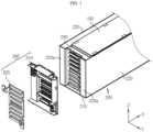
FIG. 1 is a view illustrating a battery module according to an embodiment of the present disclosure. -
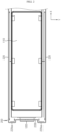
FIG. 2 is a plan view illustrating a state where a bus bar frame assembly and a fire-proof sheet are removed from the battery module ofFIG. 1 . -
FIG. 3 is a partial cross-sectional view illustrating the battery module ofFIG. 1 . -
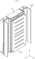
FIG. 4 is a view illustrating a state where a bus bar frame assembly and a fire-proof sheet are coupled to a module housing according to the present disclosure. -
FIG. 5 is an exploded perspective view illustrating a part of a module housing, a bus bar frame assembly, and a fire-proof sheet according to the present disclosure. -
FIG. 6 is a view illustrating a structure in which a fire-proof sheet is directly coupled to a module housing according to the present disclosure. - Hereinafter, preferred embodiments of the present disclosure will be described in detail with reference to the accompanying drawings. Prior to the description, it should be understood that the terms used in the specification and the appended claims should not be construed as limited to general and dictionary meanings, but interpreted based on the meanings and concepts corresponding to technical aspects of the present disclosure on the basis of the principle that the inventor is allowed to define terms appropriately for the best explanation. Therefore, the description proposed herein is just a preferable example for the purpose of illustrations only, not intended to limit the scope of the disclosure, so it should be understood that other equivalents and modifications could be made thereto without departing from the scope of the disclosure.
- Referring to
FIGS. 1 through 3 , a battery module according to an embodiment of the present disclosure includes a cell stack in which a plurality ofbattery cells 100 are stacked in a vertical direction (direction parallel to a Z-axis), amodule housing 200 in which the cell stack is accommodated, and a pair of busbar frame assemblies 300 covering opening portions formed on a side and the other side of themodule housing 200 in a longitudinal direction (direction parallel to an X-axis) of themodule housing 200. The battery module may further include, in addition to the above elements, a fire-proof sheet 400 located between the busbar frame assembly 300 and the cell stack and coupled to the busbar frame assembly 300. - The
battery cell 100 may be a pouch-type battery cell. In this case, thebattery cell 100 includes an electrode assembly (not shown), apouch case 110 in which the electrode assembly is accommodated, and a pair of electrode leads 120 connected to the electrode assembly and drawn out of thepouch case 110. The pair of electrode leads 120 are drawn in opposite directions in a longitudinal direction (direction parallel to the X-axis) of thebattery cell 100. - The
module housing 200 includes abase plate 210 supporting the cell stack and a pair ofside plates 220 covering both side portions of the cell stack. Each of the pair ofside plates 220 may include sparkdirection changing portions 220a formed by bending an end portion and the other end portion of theside plate 220 in a longitudinal direction of theside plate 220 toward the cell stack. - The spark
direction changing portion 220a may have a shape in which, for example, an end portion of theside plate 220 in the longitudinal direction of theside plate 220 is bent twice in a direction substantially perpendicular to an extending direction of theside plate 220. - The opening portion formed on a side of the
module housing 200 in the longitudinal direction of themodule housing 200 is formed between a pair of sparkdirection changing portions 220a respectively provided on the pair ofside plates 220. Theelectrode lead 120 of thebattery cell 100 may be exposed to the outside of themodule housing 200 through the opening portion formed between the pair of sparkdirection changing portions 220a. - Because the battery module according to an embodiment of the present disclosure includes the spark
direction changing portion 220a as described above, a spark discharged during venting of thebattery cell 100 is prevented from being ejected to the outside of themodule housing 200 in the longitudinal direction (direction parallel to the X-axis) of themodule housing 200. - That is, a high-temperature spark ejected through both side portions of the
battery cell 100 in a width direction (direction parallel to a Y-axis) of thebattery cell 100 of the cell stack during venting of thebattery cell 100 moves toward an end portion and the other end portion of the battery module in a longitudinal direction (direction parallel to the X-axis) of the battery module and then switches a moving direction toward the cell stack (see an arrow direction ofFIG. 2 ). - The
module housing 200 may further include a fasteningframe 230 connecting a pair of sparkdirection changing portions 220a that are adjacent to each other and having an empty central portion. The fasteningframe 230 is located between the busbar frame assembly 300 and the fire-proof sheet 400. When thefastening frame 230 is provided, the busbar frame assembly 300 and the fire-proof sheet 400 may be closely attached to thefastening frame 230, and may be fastened to each other through the empty central portion of thefastening frame 230. - Although not shown, the opening portions of the
module housing 200 of the present disclosure are formed on both sides of themodule housing 200 in the longitudinal direction of themodule housing 200. Accordingly, the pair of sparkdirection changing portions 220a are also provided on a side and the other side of themodule housing 200 in the longitudinal direction of themodule housing 200. - Referring to
FIGS. 1 through 5 , the busbar frame assembly 300 includes abus bar frame 310 and at least onebus bar 320. A pair of busbar frame assemblies 300 are provided, and in this case, the pair of busbar frame assemblies 300 respectively cover the opening portion formed on a side and the opening portion formed on the other side of themodule housing 200 in the longitudinal direction (direction parallel to the X-axis) of themodule housing 200. - The bus bar frames 310 cover the opening portion formed on a side and the opening portion formed on the other side of the
module housing 200 in the longitudinal direction of themodule housing 200, and are coupled to a side and the other side of the cell stack in the longitudinal direction (direction parallel to the X-axis) of the cell stack. - The
bus bar frame 310 may be formed of a resin material having electrical insulation. Thebus bar frame 310 includes a plurality of frame slits 310b through which theelectrode lead 120 of thebattery cell 100 passes. Thebus bar frame 310 may further include at least oneframe protrusion 310a protruding toward the fire-proof sheet 400 to be coupled to the fire-proof sheet assembly 400. - The
bus bar frame 310 has a shape corresponding to an end portion and the other end portion of themodule housing 200 in the longitudinal direction of themodule housing 200, that is, the sparkdirection changing portion 220a, and is closely attached to themodule housing 200. When themodule housing 200 includes thefastening frame 230 as described above, thebus bar frame 310 is closely attached to the sparkdirection changing portion 220a and thefastening frame 230. - The
bus bar 320 is located on an outer surface of thebus bar frame 310, and is coupled to theelectrode lead 120 passing through theframe slit 310b, to electrically connect the plurality ofbattery cells 100. Thebus bar 320 may include a bus bar slit 320b through which theelectrode lead 120 passes. In this case, the bus bar slit 320b and theframe slit 310b are formed at positions corresponding to each other. Theelectrode lead 120 sequentially passes through theframe slit 310b and the bus bar slit 320b and then is bent to be coupled to thebus bar 320. - Referring to
FIGS. 1 through 5 , the fire-proof sheet 400 is located between the busbar frame assembly 300 and the cell stack, and is coupled to the busbar frame assembly 300. The fire-proof sheet 400 is located on both sides of themodule housing 200 in the longitudinal direction of themodule housing 200. - The fire-
proof sheet 400 may be a sheet formed of a mica material capable of withstanding high-temperature venting gas and sparks and even fires. The fire-proof sheet 400 includes a plurality of sheet slits 400b through which theelectrode lead 120 passes. A number of sheet slits 400b corresponding to the frame slits 310b and the bus bar slits 320b are provided at positions corresponding to the frame slits 310b formed in thebus bar frame 310 and the bus bar slits 320b formed in thebus bar 320. Accordingly, theelectrode lead 120 of thebattery cell 100 sequentially passes through the sheet slit 400b of the fire-proof sheet 400 and the frame slit 310b of thebus bar frame 310 and is coupled to thebus bar 320. - Even when the
bus bar frame 310 formed of a resin material is damaged due to high-temperature venting gas and sparks, the fire-proof sheet 400 may maintain its structure, and thus, positions of the plurality of electrode leads 120 respectively inserted into the plurality ofsheet slits 400b may be maintained. Also, the fire-proof sheet 400 may allow high-temperature venting gas to be discharged to the outside through a gap between the sheet slit 400b and theelectrode lead 120, and may minimize outward ejection of a high-temperature spark containing active material and aluminum particles. Also, even when thebus bar frame 310 formed of a resin material is damaged, the fire-proof sheet 400 may prevent oxygen from being easily introduced from the outside into the battery module. - Accordingly, the fire-
proof sheet 400 may minimize the risk of a fire around thebus bar frame 310 even when an event occurs in the battery module, and even when a fire occurs around thebus bar frame 310, the fire-proof sheet 400 may delay the spread of the fire into the battery module. Also, the fire-proof sheet 400 may prevent an event from spreading due to a short circuit between thebattery cells 100 caused by damage to thebus bar frame 310. - When the
bus bar frame 310 includes theframe protrusion 310a, the fire-proof sheet 400 include at least onesheet hole 400a formed to have a position and a shape corresponding to theframe protrusion 310a for fastening to thebus bar frame 310. Theframe protrusion 310a is inserted into thesheet hole 400a to fix the fire-proof sheet 400. -
FIG. 6 illustrates a structure in which the fire-proof sheet 400 of the present disclosure is fastened to thefastening frame 230 of themodule housing 200, unlike inFIGS. 4 and5 . In this case, thefastening frame 230 may include at least onefastening protrusion 230a protruding toward the fire-proof sheet 400. - A number of
fastening protrusions 230a corresponding to the sheet holes 400a of the fire-proof sheet 400 may be provided at positions corresponding to the sheet holes 400a of the fire-proof sheet 400. Thefastening protrusion 230a is inserted into thesheet hole 400a to fix the fire-proof sheet 400. - The
module housing 200 including thefastening frame 230 may be entirely formed of a metal material to ensure rigidity of the battery module and withstand high-temperature gas and sparks discharged during an internal event. In this case, thefastening protrusion 230a may also be formed of a metal material, and thus, a fastening portion between the fire-proof sheet 400 and thefastening frame 230 may be prevented from being damaged by high-temperature gas and sparks. - A battery pack according to an embodiment of the present disclosure includes the battery module according to an embodiment of the present disclosure. Also, an energy storage system (ESS) according to an embodiment of the present disclosure includes the battery pack according to an embodiment of the present disclosure. Also, a vehicle according to an embodiment of the present disclosure includes the battery pack according to an embodiment of the present disclosure. The vehicle includes an electric vehicle.
- Although the embodiments of the present disclosure have been illustrated and described above, the present disclosure is not limited to the above-described specific embodiments. Various modified embodiments may be made by one of ordinary skill in the art without departing from the scope of the present disclosure as claimed in the claims.
Claims (13)
- A battery module comprising:a cell stack in which a plurality of battery cells are vertically stacked;a module housing comprising a base plate supporting the cell stack, and a pair of side plates covering both side portions of the cell stack and each comprising a spark direction changing portion formed by bending an end portion of the side plate in a longitudinal direction of the side plate toward the cell stack; anda bus bar frame assembly covering an opening portion formed on a side of the module housing in a longitudinal direction of the module housing, the bus bar frame assembly comprising a bus bar frame coupled to a side of the cells tack in a longitudinal direction of the cell stack and a bus bar located on the bus bar frame and coupled to an electrode lead of the battery cell.
- The battery module of claim 1, wherein the spark direction changing portion has a shape in which the side plate is bent twice in a direction perpendicular to an extending direction of the side plate.
- The battery module of claim 1, further comprising a fire-proof sheet located between the bus bar frame assembly and the cell stack.
- The battery module of claim 3, wherein the fire-proof sheet is formed of a mica material.
- The battery module of claim 3, wherein the fire-proof sheet comprises a plurality of sheet slits through which the electrode lead of the battery cell passes.
- The battery module of claim 5, wherein the bus bar frame comprises a plurality of frame slits,
wherein a number of sheet slits corresponding to the plurality of frame slits are provided at positions corresponding to the plurality of frame slits. - The battery module of claim 3, wherein the fire-proof sheet comprises at least one sheet hole.
- The battery module of claim 7, wherein the bus bar frame comprises at least one frame protrusion,
wherein the at least one frame protrusion is inserted into the at least one sheet hole to fix the fire-proof sheet. - The battery module of claim 7, wherein the module housing further comprises a fastening frame connecting a pair of spark direction changing portions.
- The battery module of claim 9, wherein the fastening frame comprises at least one fastening protrusion,
wherein the at least one fastening protrusion is inserted into the at least one sheet hole to fix the fire-proof sheet. - A battery pack comprising the battery module according to any one of claims 1 through 10.
- An energy storage system (ESS) comprising the battery pack according to claim 11.
- A vehicle comprising the battery pack according to claim 11.
Applications Claiming Priority (2)
| Application Number | Priority Date | Filing Date | Title |
|---|---|---|---|
| KR1020210006196A KR102825807B1 (en) | 2021-01-15 | 2021-01-15 | Battery module having a structure capable of preventing fire and explosion, and battery pack and ESS including the same |
| PCT/KR2022/000500 WO2022154443A1 (en) | 2021-01-15 | 2022-01-11 | Battery module and battery pack comprising same |
Publications (2)
| Publication Number | Publication Date |
|---|---|
| EP4175043A1 true EP4175043A1 (en) | 2023-05-03 |
| EP4175043A4 EP4175043A4 (en) | 2024-08-28 |
Family
ID=82447373
Family Applications (1)
| Application Number | Title | Priority Date | Filing Date |
|---|---|---|---|
| EP22739638.9A Pending EP4175043A4 (en) | 2021-01-15 | 2022-01-11 | BATTERY MODULE AND BATTERY PACK |
Country Status (6)
| Country | Link |
|---|---|
| US (1) | US20240072401A1 (en) |
| EP (1) | EP4175043A4 (en) |
| JP (2) | JP7457202B2 (en) |
| KR (1) | KR102825807B1 (en) |
| CN (1) | CN115917859A (en) |
| WO (1) | WO2022154443A1 (en) |
Families Citing this family (2)
| Publication number | Priority date | Publication date | Assignee | Title |
|---|---|---|---|---|
| KR102825807B1 (en) * | 2021-01-15 | 2025-06-25 | 주식회사 엘지에너지솔루션 | Battery module having a structure capable of preventing fire and explosion, and battery pack and ESS including the same |
| KR20250116798A (en) | 2024-01-25 | 2025-08-04 | 이종철 | Battery structure for energy storage system capable of preventing the initial spread of thermal runaway fire and extinguishing the initial fire, and battery fire extinguishing system for energy storage system including the same |
Family Cites Families (28)
| Publication number | Priority date | Publication date | Assignee | Title |
|---|---|---|---|---|
| JP2012212589A (en) * | 2011-03-31 | 2012-11-01 | Nec Energy Devices Ltd | Battery pack, and power-assisted bicycle |
| JP2015162285A (en) * | 2014-02-26 | 2015-09-07 | 日産自動車株式会社 | Battery module |
| KR101787638B1 (en) * | 2014-11-05 | 2017-10-19 | 주식회사 엘지화학 | Cartridge Frame Having Double Sidewall Structure and Battery Module Having the Same |
| KR101776898B1 (en) * | 2014-12-24 | 2017-09-08 | 주식회사 엘지화학 | Battery Module |
| CN107104211B (en) * | 2016-02-23 | 2022-01-11 | 株式会社杰士汤浅国际 | Power storage device and method for manufacturing power storage device |
| KR102065098B1 (en) * | 2016-08-12 | 2020-01-10 | 주식회사 엘지화학 | Secondary battery module improved in frame structure and frame assembly for the same |
| JP6782136B2 (en) * | 2016-09-26 | 2020-11-11 | 株式会社エンビジョンAescジャパン | Spacer and battery pack |
| JP6718845B2 (en) * | 2017-06-28 | 2020-07-08 | 本田技研工業株式会社 | Battery module |
| KR102033101B1 (en) * | 2017-09-27 | 2019-10-16 | 주식회사 엘지화학 | Battery module, battery pack and vehicle comprising the same |
| JP2019067678A (en) * | 2017-10-03 | 2019-04-25 | カルソニックカンセイ株式会社 | Assembled battery |
| KR20190054300A (en) | 2017-11-13 | 2019-05-22 | 현대자동차주식회사 | Battery |
| US20200365853A1 (en) * | 2018-02-09 | 2020-11-19 | Sanyo Electric Co., Ltd. | Power supply device, and electric vehicle and power storage device provided with said power supply device |
| KR102757247B1 (en) * | 2018-11-20 | 2025-01-17 | 주식회사 엘지에너지솔루션 | Battery module |
| CN209571443U (en) * | 2018-12-28 | 2019-11-01 | 太普动力新能源(常熟)股份有限公司 | Battery modules |
| KR102825806B1 (en) * | 2019-02-08 | 2025-06-25 | 에스케이온 주식회사 | Battery Module |
| JP7355765B2 (en) * | 2019-02-15 | 2023-10-03 | パナソニックホールディングス株式会社 | power supply |
| KR102380225B1 (en) * | 2019-03-06 | 2022-03-28 | 주식회사 엘지에너지솔루션 | A ESS module having a structure capable of preventing external exposure of a flame and a ESS pack comprising the same |
| CN111668404B (en) * | 2019-03-07 | 2024-12-03 | 宁德时代新能源科技股份有限公司 | Battery module and battery pack |
| CN209357862U (en) * | 2019-04-08 | 2019-09-06 | 宁德时代新能源科技股份有限公司 | battery cell assembly |
| KR20210006196A (en) | 2019-07-08 | 2021-01-18 | 고해선 | Method for operating remote controlling apparatus of loading bay cover of vehicle |
| CN211670261U (en) * | 2020-02-28 | 2020-10-13 | 湖北亿纬动力有限公司 | Bus bar insulation structure |
| KR102191291B1 (en) * | 2020-03-12 | 2020-12-16 | 인셀(주) | Battery enclosure for fire spread prevention, deflagration prevention and efficient cooling and inner space having it |
| KR102813264B1 (en) * | 2020-08-21 | 2025-05-27 | 주식회사 엘지에너지솔루션 | Battery Module Having Pocket For Collecting Flare and Spark |
| KR102830526B1 (en) * | 2020-07-02 | 2025-07-07 | 주식회사 엘지에너지솔루션 | Battery Module Having Pocket For Collecting Flare and Spark |
| EP4131618B1 (en) * | 2020-07-02 | 2025-06-11 | LG Energy Solution, Ltd. | Battery module having pocket capable of capturing flares and sparks ejected during swelling |
| KR102924944B1 (en) * | 2020-12-29 | 2026-02-09 | 에스케이온 주식회사 | Battery module comprising temperature sensor |
| KR102830920B1 (en) * | 2021-01-11 | 2025-07-04 | 주식회사 엘지에너지솔루션 | Battery module having a structure capable of preventing fire and explosion, and battery pack and vehicle including the same |
| KR102825807B1 (en) * | 2021-01-15 | 2025-06-25 | 주식회사 엘지에너지솔루션 | Battery module having a structure capable of preventing fire and explosion, and battery pack and ESS including the same |
-
2021
- 2021-01-15 KR KR1020210006196A patent/KR102825807B1/en active Active
-
2022
- 2022-01-11 WO PCT/KR2022/000500 patent/WO2022154443A1/en not_active Ceased
- 2022-01-11 JP JP2023504432A patent/JP7457202B2/en active Active
- 2022-01-11 US US18/270,689 patent/US20240072401A1/en active Pending
- 2022-01-11 EP EP22739638.9A patent/EP4175043A4/en active Pending
- 2022-01-11 CN CN202280005640.4A patent/CN115917859A/en active Pending
-
2024
- 2024-03-13 JP JP2024038589A patent/JP7819231B2/en active Active
Also Published As
| Publication number | Publication date |
|---|---|
| JP2023534854A (en) | 2023-08-14 |
| KR20220103509A (en) | 2022-07-22 |
| EP4175043A4 (en) | 2024-08-28 |
| WO2022154443A1 (en) | 2022-07-21 |
| US20240072401A1 (en) | 2024-02-29 |
| CN115917859A (en) | 2023-04-04 |
| JP7819231B2 (en) | 2026-02-24 |
| KR102825807B1 (en) | 2025-06-25 |
| JP7457202B2 (en) | 2024-03-27 |
| JP2024069418A (en) | 2024-05-21 |
Similar Documents
| Publication | Publication Date | Title |
|---|---|---|
| EP4175042A1 (en) | Battery module and battery pack comprising same | |
| US11777158B2 (en) | Battery module and battery pack including same | |
| EP4191777A1 (en) | Battery module and battery pack comprising same | |
| US20190363392A1 (en) | Battery module and battery pack including same | |
| EP2410594B1 (en) | Rechargeable battery | |
| EP2482361A1 (en) | Battery pack | |
| EP4195394A1 (en) | Battery pack | |
| KR102880677B1 (en) | Battery module and, battery pack and vehicle including same | |
| JP7819231B2 (en) | Battery module and battery pack including the same | |
| KR20240021501A (en) | Battery module having a structure capable of venting gas while preventing flame emission | |
| EP4199228A1 (en) | Battery module and battery pack comprising same | |
| EP4432446A1 (en) | Battery module and, battery pack comprising same and vehicle comprising same | |
| US20240380062A1 (en) | Battery pack, and ess and vehicle including the battery pack | |
| US20260011890A1 (en) | Busbar Spacer and Battery Module Including the Same | |
| EP4700958A1 (en) | Battery pack and vehicle including same | |
| EP4475280A1 (en) | Battery pack and vehicle including same | |
| KR20250137887A (en) | Battery cell and battery module including the same | |
| EP4567995A1 (en) | Battery pack and vehicle including same | |
| KR20260023162A (en) | Battery module | |
| KR20250137888A (en) | Battery module | |
| EP4621950A1 (en) | Battery module and battery pack including the same | |
| KR20250168924A (en) | Battery module including Sealing pad | |
| JP2025528375A (en) | Battery module and battery pack including said battery module | |
| KR20260051827A (en) | Battery module | |
| EP4672458A1 (en) | BATTERY PACK AND VEHICLE WITH IT |
Legal Events
| Date | Code | Title | Description |
|---|---|---|---|
| STAA | Information on the status of an ep patent application or granted ep patent |
Free format text: STATUS: THE INTERNATIONAL PUBLICATION HAS BEEN MADE |
|
| PUAI | Public reference made under article 153(3) epc to a published international application that has entered the european phase |
Free format text: ORIGINAL CODE: 0009012 |
|
| STAA | Information on the status of an ep patent application or granted ep patent |
Free format text: STATUS: REQUEST FOR EXAMINATION WAS MADE |
|
| 17P | Request for examination filed |
Effective date: 20230124 |
|
| AK | Designated contracting states |
Kind code of ref document: A1 Designated state(s): AL AT BE BG CH CY CZ DE DK EE ES FI FR GB GR HR HU IE IS IT LI LT LU LV MC MK MT NL NO PL PT RO RS SE SI SK SM TR |
|
| DAV | Request for validation of the european patent (deleted) | ||
| DAX | Request for extension of the european patent (deleted) | ||
| A4 | Supplementary search report drawn up and despatched |
Effective date: 20240731 |
|
| RIC1 | Information provided on ipc code assigned before grant |
Ipc: H01M 10/658 20140101ALI20240725BHEP Ipc: H01M 50/507 20210101ALI20240725BHEP Ipc: H01M 50/291 20210101ALI20240725BHEP Ipc: H01M 50/293 20210101ALI20240725BHEP Ipc: H01M 50/244 20210101ALI20240725BHEP Ipc: H01M 50/251 20210101ALI20240725BHEP Ipc: H01M 50/249 20210101ALI20240725BHEP Ipc: H01M 50/211 20210101ALI20240725BHEP Ipc: H01M 50/24 20210101ALI20240725BHEP Ipc: H01M 50/35 20210101ALI20240725BHEP Ipc: H01M 50/383 20210101AFI20240725BHEP |