EP4175027A1 - Battery cell having a prismatic conductive housing - Google Patents
Battery cell having a prismatic conductive housing Download PDFInfo
- Publication number
- EP4175027A1 EP4175027A1 EP21206039.6A EP21206039A EP4175027A1 EP 4175027 A1 EP4175027 A1 EP 4175027A1 EP 21206039 A EP21206039 A EP 21206039A EP 4175027 A1 EP4175027 A1 EP 4175027A1
- Authority
- EP
- European Patent Office
- Prior art keywords
- tabs
- anode
- cathode
- stack
- layer
- Prior art date
- Legal status (The legal status is an assumption and is not a legal conclusion. Google has not performed a legal analysis and makes no representation as to the accuracy of the status listed.)
- Pending
Links
Images


Classifications
-
- H—ELECTRICITY
- H01—ELECTRIC ELEMENTS
- H01M—PROCESSES OR MEANS, e.g. BATTERIES, FOR THE DIRECT CONVERSION OF CHEMICAL ENERGY INTO ELECTRICAL ENERGY
- H01M50/00—Constructional details or processes of manufacture of the non-active parts of electrochemical cells other than fuel cells, e.g. hybrid cells
- H01M50/10—Primary casings; Jackets or wrappings
- H01M50/131—Primary casings; Jackets or wrappings characterised by physical properties, e.g. gas permeability, size or heat resistance
-
- B—PERFORMING OPERATIONS; TRANSPORTING
- B60—VEHICLES IN GENERAL
- B60K—ARRANGEMENT OR MOUNTING OF PROPULSION UNITS OR OF TRANSMISSIONS IN VEHICLES; ARRANGEMENT OR MOUNTING OF PLURAL DIVERSE PRIME-MOVERS IN VEHICLES; AUXILIARY DRIVES FOR VEHICLES; INSTRUMENTATION OR DASHBOARDS FOR VEHICLES; ARRANGEMENTS IN CONNECTION WITH COOLING, AIR INTAKE, GAS EXHAUST OR FUEL SUPPLY OF PROPULSION UNITS IN VEHICLES
- B60K1/00—Arrangement or mounting of electrical propulsion units
- B60K1/04—Arrangement or mounting of electrical propulsion units of the electric storage means for propulsion
-
- H—ELECTRICITY
- H01—ELECTRIC ELEMENTS
- H01M—PROCESSES OR MEANS, e.g. BATTERIES, FOR THE DIRECT CONVERSION OF CHEMICAL ENERGY INTO ELECTRICAL ENERGY
- H01M10/00—Secondary cells; Manufacture thereof
- H01M10/04—Construction or manufacture in general
- H01M10/049—Processes for forming or storing electrodes in the battery container
-
- H—ELECTRICITY
- H01—ELECTRIC ELEMENTS
- H01M—PROCESSES OR MEANS, e.g. BATTERIES, FOR THE DIRECT CONVERSION OF CHEMICAL ENERGY INTO ELECTRICAL ENERGY
- H01M10/00—Secondary cells; Manufacture thereof
- H01M10/05—Accumulators with non-aqueous electrolyte
- H01M10/058—Construction or manufacture
- H01M10/0585—Construction or manufacture of accumulators having only flat construction elements, i.e. flat positive electrodes, flat negative electrodes and flat separators
-
- H—ELECTRICITY
- H01—ELECTRIC ELEMENTS
- H01M—PROCESSES OR MEANS, e.g. BATTERIES, FOR THE DIRECT CONVERSION OF CHEMICAL ENERGY INTO ELECTRICAL ENERGY
- H01M50/00—Constructional details or processes of manufacture of the non-active parts of electrochemical cells other than fuel cells, e.g. hybrid cells
- H01M50/10—Primary casings; Jackets or wrappings
- H01M50/102—Primary casings; Jackets or wrappings characterised by their shape or physical structure
- H01M50/103—Primary casings; Jackets or wrappings characterised by their shape or physical structure prismatic or rectangular
-
- H—ELECTRICITY
- H01—ELECTRIC ELEMENTS
- H01M—PROCESSES OR MEANS, e.g. BATTERIES, FOR THE DIRECT CONVERSION OF CHEMICAL ENERGY INTO ELECTRICAL ENERGY
- H01M50/00—Constructional details or processes of manufacture of the non-active parts of electrochemical cells other than fuel cells, e.g. hybrid cells
- H01M50/10—Primary casings; Jackets or wrappings
- H01M50/116—Primary casings; Jackets or wrappings characterised by the material
-
- H—ELECTRICITY
- H01—ELECTRIC ELEMENTS
- H01M—PROCESSES OR MEANS, e.g. BATTERIES, FOR THE DIRECT CONVERSION OF CHEMICAL ENERGY INTO ELECTRICAL ENERGY
- H01M50/00—Constructional details or processes of manufacture of the non-active parts of electrochemical cells other than fuel cells, e.g. hybrid cells
- H01M50/10—Primary casings; Jackets or wrappings
- H01M50/147—Lids or covers
- H01M50/155—Lids or covers characterised by the material
-
- H—ELECTRICITY
- H01—ELECTRIC ELEMENTS
- H01M—PROCESSES OR MEANS, e.g. BATTERIES, FOR THE DIRECT CONVERSION OF CHEMICAL ENERGY INTO ELECTRICAL ENERGY
- H01M50/00—Constructional details or processes of manufacture of the non-active parts of electrochemical cells other than fuel cells, e.g. hybrid cells
- H01M50/10—Primary casings; Jackets or wrappings
- H01M50/147—Lids or covers
- H01M50/166—Lids or covers characterised by the methods of assembling casings with lids
- H01M50/169—Lids or covers characterised by the methods of assembling casings with lids by welding, brazing or soldering
-
- H—ELECTRICITY
- H01—ELECTRIC ELEMENTS
- H01M—PROCESSES OR MEANS, e.g. BATTERIES, FOR THE DIRECT CONVERSION OF CHEMICAL ENERGY INTO ELECTRICAL ENERGY
- H01M50/00—Constructional details or processes of manufacture of the non-active parts of electrochemical cells other than fuel cells, e.g. hybrid cells
- H01M50/10—Primary casings; Jackets or wrappings
- H01M50/172—Arrangements of electric connectors penetrating the casing
- H01M50/174—Arrangements of electric connectors penetrating the casing adapted for the shape of the cells
- H01M50/176—Arrangements of electric connectors penetrating the casing adapted for the shape of the cells for prismatic or rectangular cells
-
- H—ELECTRICITY
- H01—ELECTRIC ELEMENTS
- H01M—PROCESSES OR MEANS, e.g. BATTERIES, FOR THE DIRECT CONVERSION OF CHEMICAL ENERGY INTO ELECTRICAL ENERGY
- H01M50/00—Constructional details or processes of manufacture of the non-active parts of electrochemical cells other than fuel cells, e.g. hybrid cells
- H01M50/40—Separators; Membranes; Diaphragms; Spacing elements inside cells
- H01M50/471—Spacing elements inside cells other than separators, membranes or diaphragms; Manufacturing processes thereof
- H01M50/474—Spacing elements inside cells other than separators, membranes or diaphragms; Manufacturing processes thereof characterised by their position inside the cells
-
- H—ELECTRICITY
- H01—ELECTRIC ELEMENTS
- H01M—PROCESSES OR MEANS, e.g. BATTERIES, FOR THE DIRECT CONVERSION OF CHEMICAL ENERGY INTO ELECTRICAL ENERGY
- H01M50/00—Constructional details or processes of manufacture of the non-active parts of electrochemical cells other than fuel cells, e.g. hybrid cells
- H01M50/40—Separators; Membranes; Diaphragms; Spacing elements inside cells
- H01M50/471—Spacing elements inside cells other than separators, membranes or diaphragms; Manufacturing processes thereof
- H01M50/477—Spacing elements inside cells other than separators, membranes or diaphragms; Manufacturing processes thereof characterised by their shape
-
- H—ELECTRICITY
- H01—ELECTRIC ELEMENTS
- H01M—PROCESSES OR MEANS, e.g. BATTERIES, FOR THE DIRECT CONVERSION OF CHEMICAL ENERGY INTO ELECTRICAL ENERGY
- H01M50/00—Constructional details or processes of manufacture of the non-active parts of electrochemical cells other than fuel cells, e.g. hybrid cells
- H01M50/50—Current conducting connections for cells or batteries
- H01M50/502—Interconnectors for connecting terminals of adjacent batteries; Interconnectors for connecting cells outside a battery casing
- H01M50/505—Interconnectors for connecting terminals of adjacent batteries; Interconnectors for connecting cells outside a battery casing comprising a single busbar
-
- H—ELECTRICITY
- H01—ELECTRIC ELEMENTS
- H01M—PROCESSES OR MEANS, e.g. BATTERIES, FOR THE DIRECT CONVERSION OF CHEMICAL ENERGY INTO ELECTRICAL ENERGY
- H01M50/00—Constructional details or processes of manufacture of the non-active parts of electrochemical cells other than fuel cells, e.g. hybrid cells
- H01M50/50—Current conducting connections for cells or batteries
- H01M50/528—Fixed electrical connections, i.e. not intended for disconnection
- H01M50/529—Intercell connections through partitions, e.g. in a battery casing
-
- H—ELECTRICITY
- H01—ELECTRIC ELEMENTS
- H01M—PROCESSES OR MEANS, e.g. BATTERIES, FOR THE DIRECT CONVERSION OF CHEMICAL ENERGY INTO ELECTRICAL ENERGY
- H01M50/00—Constructional details or processes of manufacture of the non-active parts of electrochemical cells other than fuel cells, e.g. hybrid cells
- H01M50/50—Current conducting connections for cells or batteries
- H01M50/531—Electrode connections inside a battery casing
- H01M50/533—Electrode connections inside a battery casing characterised by the shape of the leads or tabs
-
- H—ELECTRICITY
- H01—ELECTRIC ELEMENTS
- H01M—PROCESSES OR MEANS, e.g. BATTERIES, FOR THE DIRECT CONVERSION OF CHEMICAL ENERGY INTO ELECTRICAL ENERGY
- H01M50/00—Constructional details or processes of manufacture of the non-active parts of electrochemical cells other than fuel cells, e.g. hybrid cells
- H01M50/50—Current conducting connections for cells or batteries
- H01M50/531—Electrode connections inside a battery casing
- H01M50/536—Electrode connections inside a battery casing characterised by the method of fixing the leads to the electrodes, e.g. by welding
-
- H—ELECTRICITY
- H01—ELECTRIC ELEMENTS
- H01M—PROCESSES OR MEANS, e.g. BATTERIES, FOR THE DIRECT CONVERSION OF CHEMICAL ENERGY INTO ELECTRICAL ENERGY
- H01M50/00—Constructional details or processes of manufacture of the non-active parts of electrochemical cells other than fuel cells, e.g. hybrid cells
- H01M50/50—Current conducting connections for cells or batteries
- H01M50/543—Terminals
- H01M50/547—Terminals characterised by the disposition of the terminals on the cells
- H01M50/55—Terminals characterised by the disposition of the terminals on the cells on the same side of the cell
-
- H—ELECTRICITY
- H01—ELECTRIC ELEMENTS
- H01M—PROCESSES OR MEANS, e.g. BATTERIES, FOR THE DIRECT CONVERSION OF CHEMICAL ENERGY INTO ELECTRICAL ENERGY
- H01M50/00—Constructional details or processes of manufacture of the non-active parts of electrochemical cells other than fuel cells, e.g. hybrid cells
- H01M50/50—Current conducting connections for cells or batteries
- H01M50/543—Terminals
- H01M50/552—Terminals characterised by their shape
- H01M50/553—Terminals adapted for prismatic, pouch or rectangular cells
-
- H—ELECTRICITY
- H01—ELECTRIC ELEMENTS
- H01M—PROCESSES OR MEANS, e.g. BATTERIES, FOR THE DIRECT CONVERSION OF CHEMICAL ENERGY INTO ELECTRICAL ENERGY
- H01M50/00—Constructional details or processes of manufacture of the non-active parts of electrochemical cells other than fuel cells, e.g. hybrid cells
- H01M50/50—Current conducting connections for cells or batteries
- H01M50/543—Terminals
- H01M50/562—Terminals characterised by the material
-
- H—ELECTRICITY
- H01—ELECTRIC ELEMENTS
- H01M—PROCESSES OR MEANS, e.g. BATTERIES, FOR THE DIRECT CONVERSION OF CHEMICAL ENERGY INTO ELECTRICAL ENERGY
- H01M50/00—Constructional details or processes of manufacture of the non-active parts of electrochemical cells other than fuel cells, e.g. hybrid cells
- H01M50/50—Current conducting connections for cells or batteries
- H01M50/543—Terminals
- H01M50/564—Terminals characterised by their manufacturing process
- H01M50/566—Terminals characterised by their manufacturing process by welding, soldering or brazing
-
- H—ELECTRICITY
- H01—ELECTRIC ELEMENTS
- H01M—PROCESSES OR MEANS, e.g. BATTERIES, FOR THE DIRECT CONVERSION OF CHEMICAL ENERGY INTO ELECTRICAL ENERGY
- H01M2220/00—Batteries for particular applications
- H01M2220/20—Batteries in motive systems, e.g. vehicle, ship, plane
-
- Y—GENERAL TAGGING OF NEW TECHNOLOGICAL DEVELOPMENTS; GENERAL TAGGING OF CROSS-SECTIONAL TECHNOLOGIES SPANNING OVER SEVERAL SECTIONS OF THE IPC; TECHNICAL SUBJECTS COVERED BY FORMER USPC CROSS-REFERENCE ART COLLECTIONS [XRACs] AND DIGESTS
- Y02—TECHNOLOGIES OR APPLICATIONS FOR MITIGATION OR ADAPTATION AGAINST CLIMATE CHANGE
- Y02E—REDUCTION OF GREENHOUSE GAS [GHG] EMISSIONS, RELATED TO ENERGY GENERATION, TRANSMISSION OR DISTRIBUTION
- Y02E60/00—Enabling technologies; Technologies with a potential or indirect contribution to GHG emissions mitigation
- Y02E60/10—Energy storage using batteries
-
- Y—GENERAL TAGGING OF NEW TECHNOLOGICAL DEVELOPMENTS; GENERAL TAGGING OF CROSS-SECTIONAL TECHNOLOGIES SPANNING OVER SEVERAL SECTIONS OF THE IPC; TECHNICAL SUBJECTS COVERED BY FORMER USPC CROSS-REFERENCE ART COLLECTIONS [XRACs] AND DIGESTS
- Y02—TECHNOLOGIES OR APPLICATIONS FOR MITIGATION OR ADAPTATION AGAINST CLIMATE CHANGE
- Y02P—CLIMATE CHANGE MITIGATION TECHNOLOGIES IN THE PRODUCTION OR PROCESSING OF GOODS
- Y02P70/00—Climate change mitigation technologies in the production process for final industrial or consumer products
- Y02P70/50—Manufacturing or production processes characterised by the final manufactured product
Definitions
- the disclosure relates to a battery cell with a prismatic casing having a generally rectangular cross-section when seen in the thickness direction, a stack of layer assemblies each comprising a cathode layer, an anode layer and a separator layer there between, the layers extending in a width direction and in a height direction and being of a generally rectangular shape, a stack height extending in the thickness direction, each layer assembly comprising a cathode tab and an anode tab.
- the disclosure further relates to an electric vehicle comprising such a battery cell and to a method of manufacturing.
- Battery powered electric vehicles run on stored electricity in a battery pack that contains arrays of cells that have to be recharged once the charge is depleted.
- Car owners and drivers value a short stop at the charging station.
- transfer losses are increased significantly due high currents.
- Heat can be removed from the cells while charging using the battery pack's built-in active cooling system. Extracting heat keeps cell temperatures down, making it possible to run on higher amps for a period of time, in the end shortening charging time. Ultimately, the amount of time a customer will spend at the charging station is mainly determined by heat losses from the cell internal resistance and heat extraction by the active cooling system.
- a cylindrical battery comprising a conductive casing containing a socalled jelly roll stack of anode and cathode sheets with a separator layer in between.
- the battery cell is of a conductive can design in which the entire can forms a terminal.
- the jelly roll anode has folded internal tabs, arranged in a flower-like pattern.
- the anode material goes through a slitting machine to be cut, creating several small tabs.
- the three layers are subsequently fed though a winding machine and the internal tabs take on an overlapping configuration in the bottom plane of the jelly roll.
- the jelly roll is then inserted into the can with the anode side facing down, allowing a direct contact and electrical connection between the many tabs and the can such that each tab is capable of carrying electrical current from the anode substrate to the can.
- Integrating the cylindrical batteries into a battery pack requires a dedicated design of the battery pack for maintaining the cylinders in their proper position, such as a pre-fabricated matrix structure into which the cells are inserted and fixed in position. A similar end-effect may be obtained by using fixtures, pick and place of the cells and subsequent potting operations. Furthermore, integration of cylindrical batteries into a rectangular-shaped battery pack is less efficient from a volumetric point of view and leaves a relatively large amount of volume unoccupied by the batteries.
- a battery cell according to the disclosure comprises a prismatic conductive casing having an electrically conductive casing body with a width (W), a height (H) and a thickness (T) and having a generally rectangular cross-section when seen in the thickness direction (z),
- the battery cell according to the application is of a prismatic shape with a rectangular bottom surface that can be closely stacked in arrays forming a battery pack, for instance forming a structural battery.
- the lower tab arrangement in electrical contact with the cell casing provides for an effective electrical pathway.
- an electron When an electron is either emitted or absorbed to one of the substrate layers (anode or cathode) it only has to travel a distance (y) through the sheets and along the conductive bottom of the casing body.
- the electrons Via the conductive casing body, the electrons are conducted in the width direction (x) to or from a side surface of the cell casing and along the side surface in the height direction (y) through a side wall of the casing body.
- the electrons At the conductive cover, the electrons travel to an anode or a cathode terminal.
- the prismatic conductive housing acts as a current collector, so that no separate current collector is required. Electrons can travel across any conductive housing face in a distributed manner, to find the shortest path to the anode or cathode terminal. Current flows in a distributed manner over the entire conductive housing. This results in a more even temperature distribution and lowers the overall temperature of the battery cell.
- the battery cell of the present disclosure does not comprise a separate current collector, thus simplifying the manufacturing process and reducing cost.
- the cathode tabs or anode tabs may be placed in electrically conductive contact and in heat conducting contact with the bottom of the casing. It is favorable to contact those tabs in which most heat is generated with the conductive casing bottom.
- the cathode tabs may extend along the lower side of the stack of layer assemblies, the first terminal forming a cathode terminal, the anode tabs extending along the upper side of the stack of layer assemblies, the conductor comprising an anode conductor and the second terminal forming an anode terminal.
- a spacer member may be placed between a bottom part of the stack of layer assemblies and the bottom of the casing, the spacer member extending in the width direction (x) along the cathode tabs or the anode tabs.
- the spacer member positions the stack of anode and cathode layers at a defined distance from the bottom of the casing.
- the tab layers may extend in a straight configuration in abutting contact with the bottom.
- the spacer When the top cover is loaded during application of a downward force upon welding of the cover to the body of the housing, and/or during welding of the anode and/or cathode terminals to the tabs, the spacer prevents the internal tabs from being over compressed. The spacer also prevents excessive loads acting on the tabs as the electric vehicle moves up and down during driving conditions.
- Two or more stacks of layer assemblies can be placed in the casing, side by side in the thickness direction (z), the anode tabs and/or the cathode tabs being fused together to form a fused tab assembly, a spacer member running alongside each fused tab assembly.
- the anode and cathode sheets may be arranged in stacks or in a "jelly roll" configuration.
- the anode sheets may for instance have a thickness of 150 micrometer and the anode sheets in each layer may have a thickness of about 120 micrometer, while the separator layer may be 12 micrometer in thickness.
- Each stack may comprise between 160 and 170 layer assemblies.
- the cathode tabs and anode tabs of each layer assembly may be fused together, for instance through vibration welding, to form a fused tab assembly.
- the fused tabs may have a thickness of about 2mm-10 mm and may have a height of between 2mm and 20 mm.
- Each fused tab assembly at the lower side of each stack is flanked on both sides by a spacer member at the bottom of the casing to maintain the fused tabs in their defined and controlled configuration and to prevent buckling.
- the second terminal may comprise a circumferential wall of isolating material, extending in the height direction (y) through a hole in the cover, the circumferential wall having an inner rim with a contact surface in a plane substantially transverse to the height direction (y), onto which plane superposed cathode tabs or anode tabs are welded in a lap joint.
- the cathode tabs at the upper side of the stack of cathode and anode sheets are bent and welded onto the contact surface by exerting a downward pressure in the height direction (y) to form a fused joint.
- the circumferential wall with the welded tabs may be attached to the cover to form a pre-assembly.
- the pre-assembled stack and cover may then be combined with the casing body that receives the stack of sheets, after which the cover is welded in place.
- the second terminal comprises a support wall may be situated parallel to the top plane and having an outer edge that abuts against the casing body and in inner edge, the circumferential wall extending in the height direction (y) from the support wall at the inner edge, the cover being welded to the casing body while pressing down onto the support wall.
- the terminal is positioned in the plane of the cover by abutting against the sidewalls of the housing. After welding in position, the cover clamps the terminal firmly in place in the height direction onto the stack of layer assemblies that is supported by the spacer members.
- the second terminal may comprise a conductive terminal cap that is welded on top of the superposed cathode tabs or anode tabs.
- the terminal cap clamps the tabs against the contact surface and forms a conducting and protective seal over the tabs.
- the anode tabs or cathode tabs (51,51') may be welded to a perimeter of an elongate bus bar member (52) of a conductive material.
- the tabs extend in the height direction (y) and are welded against the peripheral side of the bus bar member.
- the bus bar member may have at a top surface a cylindrical part extending in the height direction (y), the cover comprising a hole in its top surface in which an isolating part is situated with an opening placed around the cylindrical part, placed over the bus bar member in the height direction, and having a peripheral rim that positions a cathode or anode conductor.
- a method of manufacturing a battery cell with a prismatic conductive casing having width (W), a height (Y) and a thickness (Z) and having a generally rectangular cross-section when seen in the thickness direction (z), comprises:
- the one or more spacer members allow rapid an effective positioning of the tabs at the lower side of the stack.
- the terminal may be welded to the tabs and connected to the conductive cover to form a pre-assembly. After the stack is lowered into the casing body while placing the cover onto the body, the terminal is clamped between the cover and the top surface of the layer assemblies. The cover is sealed onto the casing body while the lower tabs are positioned in conductive contact with the casing bottom via the one or more spacer members.
- the contact member may a circumferential wall having an inner rim with a contact surface in a plane substantially transverse to the height direction (y), the tabs at the upper side being superposed onto the contact surface and are welded in a lap joint condition by exerting a compressive force on the tabs in the height direction (y).
- the tabs are folded onto the contact member and welded firmly in place by the compressive force exerted by the welding tool.
- a conducting cap may be welded onto the tabs at the upper side by exerting a compressive force in the height direction (y).
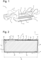
- Figure 1 shows a frame 1 of an electric vehicle, comprising a front frame structure 2, a rear frame structure 3, including a rear floor, and a structural battery pack 4, forming a bottom structure 5 of the vehicle.
- the structural battery pack 4 comprises longitudinal sill profiles 6,7 that interconnect the front and rear frame structures 2,3 and that support a number of rows of interconnected prismatic battery cells 9.
- the top plate 10 of the battery pack 4 forms the bottom of the cabin of the vehicle.
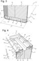
- Figure 2 shows a cross-sectional view of a prismatic battery cell 12, for instance an electrochemical Lithium-ion battery cell, with a rectangular cross-section and a rectangular-shaped footprint, having a width W of for instance 286 mm, a height H of 110 mm and a thickness T of 30mm.
- the battery cell 12 comprises a casing 13 with a conductive casing body 14 and a conductive cover 15, for instance made of aluminium.
- the casing 13 accommodates one or more stacks 16 of layer assemblies, each layer assembly comprising an anode layer, a cathode layer and a separator (isolation) layer, interposed between the anode and cathode layers.
- the layer assemblies extend in the x- and y directions in the plane of the drawing, and are stacked in a direction perpendicular to the plane of the drawing.
- Each stack 16 may comprise 160 or more layer assemblies in a z-stacked or jelly roll configuration.
- Each stack 16 comprises cathode tabs 18 extending along a lower part 19 of the stack.
- the cathode tabs 18 are in electrically conducting contact with a conductive bottom 20 of the casing 13 and extend along the width W of the casing 13.
- the stack 16 comprise anode tabs 22 at an upper part 23 of the stack 16, extending along a part of the width W and passing through an aperture in an insulating lower cover member 17, that is placed on the stack 16, below the conductive cover 15.
- the anode tabs 22 are connected to an anode terminal 24 that is electrically isolated from the cover 15.
- a cathode terminal 25 is electrically connected to the cover 15.
- Electrons that are absorbed in a region 30 of the stack 16 of layer assemblies will, as schematically indicated by the arrows, travel from the cathode terminal 25, via the cover 15, along the sidewall 26 and the conductive bottom 20 of the casing to the respective cathode tab 18 and pass from the cathode tab 18 upwards to the region 30.
- Figure 3 shows two stacks 16,16' of electrode and separator layer assemblies that are arranged side by side in the thickness direction z of the casing 13.
- the cathode tabs 18,18' of the layers in each stack 16,16' are fused together and are placed substantially transversely onto the conductive bottom 20.
- Spacer members 32,33,34 support the stacks 16,16' and are placed on the bottom 20, extending in the width direction x alongside the cathode tabs 18,18'.
- the spacer members 32,33 and 34 can be made of a plastic material.
- Figure 4 shows a part of the anode terminal 24 having an isolating support wall 38 that is clamped between the top plane 37 of the cover 15 and an upper sides 39, 39' of the stacks 16, 16'.
- the cover 15 is laser welded to the side walls 26 of the cell casing, along a weld 40.
- An inner edge 41 of the support wall 38 abuts against the side wall 26 of the casing 13.
- a circumferential wall 43 extends upwards through a hole in the cover 15.
- the circumferential wall 43 has a contact surface 44 onto which the anode tabs 22, 22' are welded in a lap joint in weld areas 45,45', which may be formed by ultrasonic welds.
- the anode tabs 22,22' are bonded together by vibration welding or a similar welding technique to form a fused anode tab for each stack 16, 16'.
- Figure 5 shows a protective terminal cap 48 of conductive material being placed within the upper part of circumferential wall 43 and welded onto the anode tabs 22 in the weld area 45 to complete the anode terminal 24.
- FIG 6 shows an embodiment in which anode tabs 51, 51'of two stacks 50, 50' of electrode and separator layer assemblies are welded to the perimeter of an elongate bus bar 52.
- the bus bar 52 may be formed of aluminum or copper and has a cylindrical stub 53 that is received in a tight fit in a cover member 55, that forms an insulator, as shown in figures 7 and 9 .
- the stub 53 is welded to an anode terminal 56.
- Figure 7 shows a cross-sectional view of the tabs 51,51' extending in the height direction and being welded to the longitudinal sides of the busbar 52.
- the busbar 52 is conductively connected to the anode terminal 56, that is received in the electrically isolating cover member 55.
- Conducting cover 59 is welded to the side walls 58 and seals the battery cell.
- Figure 8 shows a perspective view of the cover member 55 and the anode terminal 56, with the cover 59 removed.
- FIG 9 it can be seen that the insulating cover member 55 is clamped between the conducting cover 59 of the housing, that is welded onto the cell casing side walls 58.
- the exploded view of figure 10 shows a sealing ring 60 that is placed around the stub 53 and provides a tight seal between the anode terminal 56 and the isolation cover member 55, preventing moisture or contamination from entering the battery cell.
- Figure 11 shows the prismatic battery cell with a rectangular-shaped footprint, with the conductive cover 59 welded to the casing body 61, a cathode terminal 62 embedded in the cover 59 and the anode terminal 56 conductively connected to the anode tabs via the cylindrical stub 53.
Landscapes
- Chemical & Material Sciences (AREA)
- Chemical Kinetics & Catalysis (AREA)
- Electrochemistry (AREA)
- General Chemical & Material Sciences (AREA)
- Engineering & Computer Science (AREA)
- Manufacturing & Machinery (AREA)
- Combustion & Propulsion (AREA)
- Transportation (AREA)
- Mechanical Engineering (AREA)
- Connection Of Batteries Or Terminals (AREA)
Abstract
Description
- The disclosure relates to a battery cell with a prismatic casing having a generally rectangular cross-section when seen in the thickness direction, a stack of layer assemblies each comprising a cathode layer, an anode layer and a separator layer there between, the layers extending in a width direction and in a height direction and being of a generally rectangular shape, a stack height extending in the thickness direction, each layer assembly comprising a cathode tab and an anode tab.
- The disclosure further relates to an electric vehicle comprising such a battery cell and to a method of manufacturing.
- Battery powered electric vehicles (BEV) run on stored electricity in a battery pack that contains arrays of cells that have to be recharged once the charge is depleted. Car owners and drivers value a short stop at the charging station. During charging, transfer losses are increased significantly due high currents. As the generation of heat during recharging can be limited by reducing the current, charging times are extended.
- Heat can be removed from the cells while charging using the battery pack's built-in active cooling system. Extracting heat keeps cell temperatures down, making it possible to run on higher amps for a period of time, in the end shortening charging time. Ultimately, the amount of time a customer will spend at the charging station is mainly determined by heat losses from the cell internal resistance and heat extraction by the active cooling system.
- A cylindrical battery is known, comprising a conductive casing containing a socalled jelly roll stack of anode and cathode sheets with a separator layer in between. The battery cell is of a conductive can design in which the entire can forms a terminal. The jelly roll anode has folded internal tabs, arranged in a flower-like pattern. The anode material goes through a slitting machine to be cut, creating several small tabs. The three layers are subsequently fed though a winding machine and the internal tabs take on an overlapping configuration in the bottom plane of the jelly roll. The jelly roll is then inserted into the can with the anode side facing down, allowing a direct contact and electrical connection between the many tabs and the can such that each tab is capable of carrying electrical current from the anode substrate to the can.
- Integrating the cylindrical batteries into a battery pack requires a dedicated design of the battery pack for maintaining the cylinders in their proper position, such as a pre-fabricated matrix structure into which the cells are inserted and fixed in position. A similar end-effect may be obtained by using fixtures, pick and place of the cells and subsequent potting operations. Furthermore, integration of cylindrical batteries into a rectangular-shaped battery pack is less efficient from a volumetric point of view and leaves a relatively large amount of volume unoccupied by the batteries.
- It is an object of the present development to provide a battery cell for use in an electric vehicle that allows fast charging with reduced heat development. It is another object to provide a battery cell that is of a relatively simple and light-weight design and can be fitted efficiently in a battery pack a with a rectangular-shaped footprint. It is another object of the present development to provide for an effective method of manufacturing a battery cell.
- A battery cell according to the disclosure comprises a prismatic conductive casing having an electrically conductive casing body with a width (W), a height (H) and a thickness (T) and having a generally rectangular cross-section when seen in the thickness direction (z),
- a stack of layer assemblies accommodated in the casing body, each layer assembly comprising a cathode layer, an anode layer and a separator layer there between, the layers extending in a width direction (x) and in a height direction (y) and being of a generally rectangular shape, a stack height extending in the thickness direction (z),
- the cathode and anode layers each comprising a cathode tab and an anode tab, respectively,
- one of the cathode tabs and anode tabs extending in the width direction (x) along a lower side of the stack (of layer assemblies, substantially along the width (W) of the casing and being in conductive contact with a bottom of the casing,
- a conductive cover being attached to the casing body and defining a top plane of the battery cell, a first terminal being situated at or near the top plane, conductively connected to the cover,
- the other of the cathode tabs and anode tabs extending in the width direction (x) along a section of an upper side of the stack of layer assemblies, and being connected to a conductor, the conductor extending via an opening in the cover to at or near the top plane and connected to the cover via an insulator member forming a second terminal at or near the top plane of the cell.
- The battery cell according to the application is of a prismatic shape with a rectangular bottom surface that can be closely stacked in arrays forming a battery pack, for instance forming a structural battery.
- The lower tab arrangement in electrical contact with the cell casing provides for an effective electrical pathway. When an electron is either emitted or absorbed to one of the substrate layers (anode or cathode) it only has to travel a distance (y) through the sheets and along the conductive bottom of the casing body. Via the conductive casing body, the electrons are conducted in the width direction (x) to or from a side surface of the cell casing and along the side surface in the height direction (y) through a side wall of the casing body. At the conductive cover, the electrons travel to an anode or a cathode terminal. The shortened distance from the point of electron emission (or absorption) inside a substrate to cell exit (or entry) at the terminals, located on the cell top-side, results in reduced heat losses since electrical losses are a function of distance and resistance.
- In the present development, the prismatic conductive housing acts as a current collector, so that no separate current collector is required. Electrons can travel across any conductive housing face in a distributed manner, to find the shortest path to the anode or cathode terminal. Current flows in a distributed manner over the entire conductive housing. This results in a more even temperature distribution and lowers the overall temperature of the battery cell.
- The battery cell of the present disclosure does not comprise a separate current collector, thus simplifying the manufacturing process and reducing cost.
- The cathode tabs or anode tabs may be placed in electrically conductive contact and in heat conducting contact with the bottom of the casing. It is favorable to contact those tabs in which most heat is generated with the conductive casing bottom.
- In a battery cell, the cathode tabs may extend along the lower side of the stack of layer assemblies, the first terminal forming a cathode terminal, the anode tabs extending along the upper side of the stack of layer assemblies, the conductor comprising an anode conductor and the second terminal forming an anode terminal.
- A spacer member may be placed between a bottom part of the stack of layer assemblies and the bottom of the casing, the spacer member extending in the width direction (x) along the cathode tabs or the anode tabs.
- The spacer member positions the stack of anode and cathode layers at a defined distance from the bottom of the casing. The tab layers may extend in a straight configuration in abutting contact with the bottom.
- When the top cover is loaded during application of a downward force upon welding of the cover to the body of the housing, and/or during welding of the anode and/or cathode terminals to the tabs, the spacer prevents the internal tabs from being over compressed. The spacer also prevents excessive loads acting on the tabs as the electric vehicle moves up and down during driving conditions.
- Two or more stacks of layer assemblies can be placed in the casing, side by side in the thickness direction (z), the anode tabs and/or the cathode tabs being fused together to form a fused tab assembly, a spacer member running alongside each fused tab assembly.
- The anode and cathode sheets may be arranged in stacks or in a "jelly roll" configuration. The anode sheets may for instance have a thickness of 150 micrometer and the anode sheets in each layer may have a thickness of about 120 micrometer, while the separator layer may be 12 micrometer in thickness. Each stack may comprise between 160 and 170 layer assemblies. The cathode tabs and anode tabs of each layer assembly may be fused together, for instance through vibration welding, to form a fused tab assembly. The fused tabs may have a thickness of about 2mm-10 mm and may have a height of between 2mm and 20 mm.
- Several stacks of sheets may be accommodated in the housing, side by side. Each fused tab assembly at the lower side of each stack is flanked on both sides by a spacer member at the bottom of the casing to maintain the fused tabs in their defined and controlled configuration and to prevent buckling.
- In a battery cell, the second terminal may comprise a circumferential wall of isolating material, extending in the height direction (y) through a hole in the cover, the circumferential wall having an inner rim with a contact surface in a plane substantially transverse to the height direction (y), onto which plane superposed cathode tabs or anode tabs are welded in a lap joint.
- The cathode tabs at the upper side of the stack of cathode and anode sheets, are bent and welded onto the contact surface by exerting a downward pressure in the height direction (y) to form a fused joint. The circumferential wall with the welded tabs may be attached to the cover to form a pre-assembly. The pre-assembled stack and cover may then be combined with the casing body that receives the stack of sheets, after which the cover is welded in place.
- The second terminal comprises a support wall may be situated parallel to the top plane and having an outer edge that abuts against the casing body and in inner edge, the circumferential wall extending in the height direction (y) from the support wall at the inner edge, the cover being welded to the casing body while pressing down onto the support wall. The terminal is positioned in the plane of the cover by abutting against the sidewalls of the housing. After welding in position, the cover clamps the terminal firmly in place in the height direction onto the stack of layer assemblies that is supported by the spacer members.
- In a battery cell, the second terminal may comprise a conductive terminal cap that is welded on top of the superposed cathode tabs or anode tabs.
- The terminal cap clamps the tabs against the contact surface and forms a conducting and protective seal over the tabs.
- The anode tabs or cathode tabs (51,51') may be welded to a perimeter of an elongate bus bar member (52) of a conductive material.
- The tabs extend in the height direction (y) and are welded against the peripheral side of the bus bar member.
- The bus bar member may have at a top surface a cylindrical part extending in the height direction (y), the cover comprising a hole in its top surface in which an isolating part is situated with an opening placed around the cylindrical part, placed over the bus bar member in the height direction, and having a peripheral rim that positions a cathode or anode conductor.
- A method of manufacturing a battery cell with a prismatic conductive casing having width (W), a height (Y) and a thickness (Z) and having a generally rectangular cross-section when seen in the thickness direction (z), comprises:
- placing a spacer member at a bottom of a casing body,
- placing a stack (of layer assemblies each comprising a cathode layer, an anode layer and a separator layer there between, the stack comprising cathode tabs and anode tabs and being of a generally rectangular shape, in the casing body, such that the layers extend in a width direction (x) and in a height direction (y), a stack height extending in the thickness direction (z),
- placing one of the anode tabs and the cathode tabs that extend along a lower side of the stack of layer assemblies, substantially along the width (W) of the casing, and alongside the spacer member in conductive contact with the bottom, the other of the anode tabs and cathode tabs being situated along an upper side,
- welding the tabs at the upper side to a contact member of a terminal, and
- attaching a conductive cover to the casing body, the cover having an opening through which the contact member projects in the height direction, while exerting a compressive force in the height direction, clamping the contact member between the cover and the top of the stack of layer assemblies.
- The one or more spacer members allow rapid an effective positioning of the tabs at the lower side of the stack. The terminal may be welded to the tabs and connected to the conductive cover to form a pre-assembly. After the stack is lowered into the casing body while placing the cover onto the body, the terminal is clamped between the cover and the top surface of the layer assemblies. The cover is sealed onto the casing body while the lower tabs are positioned in conductive contact with the casing bottom via the one or more spacer members.
- The contact member may a circumferential wall having an inner rim with a contact surface in a plane substantially transverse to the height direction (y), the tabs at the upper side being superposed onto the contact surface and are welded in a lap joint condition by exerting a compressive force on the tabs in the height direction (y).
- The tabs are folded onto the contact member and welded firmly in place by the compressive force exerted by the welding tool.
- A conducting cap may be welded onto the tabs at the upper side by exerting a compressive force in the height direction (y).
- Embodiments of battery cell will by way of non-limiting example be described in detail with reference to the accompanying drawings. In the drawings:
-
Fig. 1 shows a battery pack formed of prismatic battery cells with a rectangular-shaped bottom surface, connected to a front and rear frame part of an electric vehicle, -
Fig. 2 shows a cross-sectional side view of a battery cell according to the disclosure, in the thickness direction, -
Fig. 3 shows a perspective cross-sectional view of a lower part of a battery cell, -
Fig. 4 shows a perspective cross-sectional view of an upper part of a battery cell, -
Fig. 5 shows a cross-sectional view of a part of an anode terminal, -
Fig. 6 shows an embodiment of two stacks of electrode and separator sheet assemblies connected to a bus bar member, -
Fig. 7 shows a cross-sectional view of an upper part of a battery cell, comprising the embodiment offigure 6 , -
Fig. 8 shows the stacks offigure 6 with the anode terminal connected to an insulating cover member, -
Fig. 9 shows a cross-sectional view of abattery cell 7, comprising the embodiment offigure 6 , with the conductive cover in place, -
Fig. 10 shows an exploded view of a sealing ring of the anode terminal, and -
Fig. 11 shows a perspective view the battery cell offigs. 7 and9 . -
Figure 1 shows aframe 1 of an electric vehicle, comprising afront frame structure 2, arear frame structure 3, including a rear floor, and astructural battery pack 4, forming abottom structure 5 of the vehicle. Thestructural battery pack 4 compriseslongitudinal sill profiles rear frame structures prismatic battery cells 9. Thetop plate 10 of thebattery pack 4 forms the bottom of the cabin of the vehicle. -
Figure 2 shows a cross-sectional view of aprismatic battery cell 12, for instance an electrochemical Lithium-ion battery cell, with a rectangular cross-section and a rectangular-shaped footprint, having a width W of for instance 286 mm, a height H of 110 mm and a thickness T of 30mm. Thebattery cell 12 comprises acasing 13 with aconductive casing body 14 and aconductive cover 15, for instance made of aluminium. - The
casing 13 accommodates one ormore stacks 16 of layer assemblies, each layer assembly comprising an anode layer, a cathode layer and a separator (isolation) layer, interposed between the anode and cathode layers. The layer assemblies extend in the x- and y directions in the plane of the drawing, and are stacked in a direction perpendicular to the plane of the drawing. Eachstack 16 may comprise 160 or more layer assemblies in a z-stacked or jelly roll configuration. - Each
stack 16 comprisescathode tabs 18 extending along alower part 19 of the stack. Thecathode tabs 18 are in electrically conducting contact with aconductive bottom 20 of thecasing 13 and extend along the width W of thecasing 13. - The
stack 16 compriseanode tabs 22 at anupper part 23 of thestack 16, extending along a part of the width W and passing through an aperture in an insulatinglower cover member 17, that is placed on thestack 16, below theconductive cover 15. Theanode tabs 22 are connected to ananode terminal 24 that is electrically isolated from thecover 15. Acathode terminal 25 is electrically connected to thecover 15. - Electrons that are absorbed in a
region 30 of thestack 16 of layer assemblies, will, as schematically indicated by the arrows, travel from thecathode terminal 25, via thecover 15, along thesidewall 26 and theconductive bottom 20 of the casing to therespective cathode tab 18 and pass from thecathode tab 18 upwards to theregion 30. -
Figure 3 shows twostacks 16,16' of electrode and separator layer assemblies that are arranged side by side in the thickness direction z of thecasing 13. Thecathode tabs 18,18' of the layers in eachstack 16,16'are fused together and are placed substantially transversely onto theconductive bottom 20.Spacer members stacks 16,16' and are placed on the bottom 20, extending in the width direction x alongside thecathode tabs 18,18'. Thespacer members -
Figure 4 shows a part of theanode terminal 24 having an isolatingsupport wall 38 that is clamped between thetop plane 37 of thecover 15 and anupper sides 39, 39' of thestacks 16, 16'. Thecover 15 is laser welded to theside walls 26 of the cell casing, along aweld 40. Aninner edge 41 of thesupport wall 38 abuts against theside wall 26 of thecasing 13. At anouter edge 42 of thesupport wall 41, acircumferential wall 43 extends upwards through a hole in thecover 15. Thecircumferential wall 43 has acontact surface 44 onto which theanode tabs 22, 22' are welded in a lap joint inweld areas 45,45', which may be formed by ultrasonic welds. At the weld area's 46, 46', theanode tabs 22,22' are bonded together by vibration welding or a similar welding technique to form a fused anode tab for eachstack 16, 16'. -
Figure 5 shows aprotective terminal cap 48 of conductive material being placed within the upper part ofcircumferential wall 43 and welded onto theanode tabs 22 in theweld area 45 to complete theanode terminal 24. -
Figure 6 shows an embodiment in which anodetabs 51, 51'of twostacks 50, 50' of electrode and separator layer assemblies are welded to the perimeter of anelongate bus bar 52. Thebus bar 52 may be formed of aluminum or copper and has acylindrical stub 53 that is received in a tight fit in acover member 55, that forms an insulator, as shown infigures 7 and9 .Thestub 53 is welded to ananode terminal 56. -
Figure 7 shows a cross-sectional view of thetabs 51,51' extending in the height direction and being welded to the longitudinal sides of thebusbar 52. Thebusbar 52 is conductively connected to theanode terminal 56, that is received in the electrically isolatingcover member 55. Conductingcover 59 is welded to theside walls 58 and seals the battery cell. -
Figure 8 shows a perspective view of thecover member 55 and theanode terminal 56, with thecover 59 removed. - In
figure 9 it can be seen that the insulatingcover member 55 is clamped between the conductingcover 59 of the housing, that is welded onto the cellcasing side walls 58. The exploded view offigure 10 shows a sealingring 60 that is placed around thestub 53 and provides a tight seal between theanode terminal 56 and theisolation cover member 55, preventing moisture or contamination from entering the battery cell. -
Figure 11 shows the prismatic battery cell with a rectangular-shaped footprint, with theconductive cover 59 welded to thecasing body 61, acathode terminal 62 embedded in thecover 59 and theanode terminal 56 conductively connected to the anode tabs via thecylindrical stub 53.
Claims (13)
- Battery cell (12) comprising a prismatic conductive casing (13) having an electrically conductive casing body (14) with a width (W), a height (H) and a thickness (T) and having a generally rectangular cross-section when seen in the thickness direction (z),a stack (16,16') of layer assemblies accommodated in the casing body, each layer assembly comprising a cathode layer, an anode layer and a separator layer there between, the layers extending in a width direction (x) and in a height direction (y) and being of a generally rectangular shape, a stack height extending in the thickness direction (z),the cathode and anode layers each comprising a cathode tab and an anode tab, respectively,one of the cathode tabs (22,51,51') and anode tabs (18,18') extending in the width direction (x) along a lower part (19) of the stack (16,16') of layer assemblies, substantially along the width (W) of the casing (13) and being in conductive contact with a bottom (20) of the casing (13),a conductive cover (15,59) being attached to the casing body (14) and defining a top plane (37) of the battery cell (12), a first terminal (25) being situated at or near the top plane, conductively connected to the cover (15,59),the other of the cathode tabs (22,51,51') and anode tabs (18,18') extending in the width direction (x) along a section of an upper part (23) of the stack (16,16') of layer assemblies, and being connected to a conductor (48,52,53), the conductor (48,52,53) extending via an opening in the cover (15,59) to at or near the top plane (37) and connected to the cover (15,59) via an insulator member (17,38,43, 44,55), the conductor (48,52,53) forming a second terminal (24,56) associated to the top plane (37) of the cell.
- Battery cell (2) according to claim 1, the cathode tabs (18,18') extending along the lower part (19) of the stack (16,16') of layer assemblies, the first terminal (25) forming a cathode terminal, the anode tabs (22,51,51') extending along the upper part (23) of the stack (16,16') of layer assemblies, the conductor (48,52,53) comprising an anode conductor and the second terminal (24,56) forming an anode terminal.
- Battery cell (12) according to claim 1 or 2, a spacer member (32,33,34) being placed between a bottom part (19) of the stack (16,16') of layer assemblies and the bottom (20) of the casing (13), the spacer member (32,33,34) extending in the width direction (x) along the cathode tabs or the anode tabs (18,18').
- Battery cell (12) according to claim 1 or 2, two or more stacks (16,16') of layer assemblies being placed in the casing (13), side by side in the thickness direction (z), the anode tabs (18,18') and/or the cathode tabs (22,51,51') being fused together to form a fused tab assembly, a spacer member (32,33,34) running alongside each fused tab assembly between a bottom part (19) of the stack (16,16') of layer assemblies and the bottom (20) of the casing (13).
- Battery cell (12) according to any of the preceding claims, the second terminal (24) comprising a circumferential wall (43) of isolating material, extending in the height direction (y) away from the cover, through a hole in the cover (15,59), the circumferential wall (43) having an inner rim (44) with a contact surface in a plane substantially transverse to the height direction (y), onto which plane superposed cathode tabs (22,22') or anode tabs are welded in a lap joint.
- Battery cell (12) according to claim 5, wherein the second terminal (24) comprises a support wall (38) situated parallel to the top plane (37) and having an outer edge (41) that abuts against the casing body (14,26) and in inner edge (42), the circumferential wall (43) extending in the height direction (y) from the support wall (38) at the inner edge (42), the cover (15,59) being welded to the casing body (14) while pressing down onto the support wall (38).
- Battery cell (12) according to claim 5 or 6, wherein the second terminal (24) comprises a conductive terminal cap (48) that is welded on top of the superposed cathode tabs (22,22') or anode tabs.
- Battery cell (12) according to any of claims 1-4, the anode tabs or cathode tabs (51,51') being welded to a perimeter of an elongate bus bar member (52) of a conductive material.
- Battery cell (12) according to claim 8, the bus bar member (52) having at a top surface a cylindrical part (53) extending in the height direction (y), the cover (15,59) comprising a hole in its top surface in which an isolating part (55) is situated with an opening placed around the cylindrical part (53), placed over the bus bar member (52) and having a peripheral rim that positions a cathode or anode conductor (56).
- Electric vehicle comprising at least one battery cell according to any of the preceding claims.
- Method of manufacturing a battery cell (12) with a prismatic conductive casing (13) having width (W), a height (Y) and a thickness (Z) and having a generally rectangular cross-section when seen in the thickness direction (z), comprising:- placing a spacer member (32,33,34) at a bottom (20) of a casing body (14,61),- placing a stack (16,16',50,50) of layer assemblies each comprising a cathode layer, an anode layer and a separator layer there between, the stack (16,16',50,50) comprising cathode tabs and anode tabs and being of a generally rectangular shape, in the casing body (14,61), such that the layers extend in a width direction (x) and in a height direction (y), a stack height extending in the thickness direction (z),- placing one of the anode tabs (18,18') and the cathode tabs (22,51,51') that extend along a lower part (19) of the stack (16,16') of layer assemblies, substantially along the width (W) of the casing (13), and alongside the spacer member (32,33,34) in conductive contact with the bottom (20), the other of the anode tabs (18,18') and cathode tabs (22,51,51') being situated along an upper part (23),- welding the tabs (22,51,51') at the upper part (23) to a contact member (44,52) of a terminal (24,56), and- attaching a conductive cover (15,59) to the casing body (14,61), the cover (15,59) having an opening through which the contact member (43,44,52) projects in the height direction (y), while exerting a compressive force in the height direction (y), clamping the contact member (43,44,52) between the cover (15,59) and the top (39,39') of the stack (16,16',50,50') of layer assemblies.
- Method according to claim 10, the contact member comprising a circumferential wall (43) having an inner rim (44) with a contact surface in a plane substantially transverse to the height direction (y), the tabs (22,22') at the upper part (23) being superposed onto the contact surface and are welded in a lap joint condition by exerting a compressive force on the tabs in the height direction (y).
- Method according to claim 11, comprising welding of a conducting cap (48) onto the tabs (22,22') at the upper part (23) by exerting a compressive force in the height direction (y).
Priority Applications (3)
| Application Number | Priority Date | Filing Date | Title |
|---|---|---|---|
| EP21206039.6A EP4175027A1 (en) | 2021-11-02 | 2021-11-02 | Battery cell having a prismatic conductive housing |
| US17/971,682 US12537247B2 (en) | 2021-11-02 | 2022-10-24 | Battery cell having a prismatic conductive housing |
| CN202211361086.1A CN116073037A (en) | 2021-11-02 | 2022-11-02 | Battery cell with prismatic conductive housing |
Applications Claiming Priority (1)
| Application Number | Priority Date | Filing Date | Title |
|---|---|---|---|
| EP21206039.6A EP4175027A1 (en) | 2021-11-02 | 2021-11-02 | Battery cell having a prismatic conductive housing |
Publications (1)
| Publication Number | Publication Date |
|---|---|
| EP4175027A1 true EP4175027A1 (en) | 2023-05-03 |
Family
ID=78500541
Family Applications (1)
| Application Number | Title | Priority Date | Filing Date |
|---|---|---|---|
| EP21206039.6A Pending EP4175027A1 (en) | 2021-11-02 | 2021-11-02 | Battery cell having a prismatic conductive housing |
Country Status (3)
| Country | Link |
|---|---|
| US (1) | US12537247B2 (en) |
| EP (1) | EP4175027A1 (en) |
| CN (1) | CN116073037A (en) |
Families Citing this family (4)
| Publication number | Priority date | Publication date | Assignee | Title |
|---|---|---|---|---|
| US12609418B2 (en) * | 2022-12-21 | 2026-04-21 | Meta Platforms Technologies, Llc | Metal can battery with stepped enclosure |
| EP4465394A1 (en) * | 2023-05-16 | 2024-11-20 | Automotive Cells Company SE | Electrochemical cell for an electric battery |
| DE102023132847A1 (en) * | 2023-11-24 | 2025-05-28 | Carl Freudenberg Kg | Cover assembly for a prismatic cell |
| DE102023132846A1 (en) * | 2023-11-24 | 2025-05-28 | Carl Freudenberg Kg | Cover assembly for a prismatic cell |
Citations (2)
| Publication number | Priority date | Publication date | Assignee | Title |
|---|---|---|---|---|
| US5549717A (en) * | 1994-03-03 | 1996-08-27 | Wilson Greatbatch Ltd. | Method of making prismatic cell |
| EP3151305A1 (en) * | 2015-10-02 | 2017-04-05 | Samsung SDI Co., Ltd. | Secondary battery |
Family Cites Families (4)
| Publication number | Priority date | Publication date | Assignee | Title |
|---|---|---|---|---|
| KR102263199B1 (en) * | 2014-11-12 | 2021-06-10 | 삼성에스디아이 주식회사 | A secondary battery |
| DE102015207070A1 (en) * | 2015-04-17 | 2016-10-20 | Varta Microbattery Gmbh | Battery with prismatic metal housing |
| KR102517901B1 (en) * | 2015-10-02 | 2023-04-03 | 삼성에스디아이 주식회사 | Rechargeable battery |
| JP6859851B2 (en) * | 2017-05-31 | 2021-04-14 | 三洋電機株式会社 | Square secondary batteries, assembled batteries and vehicles using them |
-
2021
- 2021-11-02 EP EP21206039.6A patent/EP4175027A1/en active Pending
-
2022
- 2022-10-24 US US17/971,682 patent/US12537247B2/en active Active
- 2022-11-02 CN CN202211361086.1A patent/CN116073037A/en active Pending
Patent Citations (2)
| Publication number | Priority date | Publication date | Assignee | Title |
|---|---|---|---|---|
| US5549717A (en) * | 1994-03-03 | 1996-08-27 | Wilson Greatbatch Ltd. | Method of making prismatic cell |
| EP3151305A1 (en) * | 2015-10-02 | 2017-04-05 | Samsung SDI Co., Ltd. | Secondary battery |
Also Published As
| Publication number | Publication date |
|---|---|
| US12537247B2 (en) | 2026-01-27 |
| CN116073037A (en) | 2023-05-05 |
| US20230139645A1 (en) | 2023-05-04 |
Similar Documents
| Publication | Publication Date | Title |
|---|---|---|
| US12537247B2 (en) | Battery cell having a prismatic conductive housing | |
| KR102883761B1 (en) | Battery cells, batteries and power consumption devices | |
| KR100599732B1 (en) | Secondary battery | |
| US20240154218A1 (en) | Battery cell, battery, and electrical apparatus | |
| JP4515373B2 (en) | Secondary battery | |
| US20110244287A1 (en) | Method for manufacturing secondary cell and secondary cell | |
| EP4266475A2 (en) | Battery, battery assembly method, and battery pack | |
| KR102160276B1 (en) | Battery module, battery pack comprising the battery module and vehicle comprising the battery pack | |
| US20170309870A1 (en) | Multicavity Battery Module | |
| KR100612236B1 (en) | Secondary Battery and Electrode Assembly Used in the Same | |
| KR20170109232A (en) | Battery cell and battery system | |
| KR20180124093A (en) | An electrochemical cell including an electrode separation frame | |
| KR20180026945A (en) | Battery module and battery pack including the same | |
| KR102798697B1 (en) | Secondary battery and method of manufacturing the same | |
| US10263291B2 (en) | Method of producing a prismatic battery cell | |
| US20230207859A1 (en) | Secondary battery | |
| EP4181255B1 (en) | Method of manufacturing secondary battery | |
| KR20250020103A (en) | Battery module and battery pack including the same | |
| US10170812B2 (en) | Assembly module comprising electrochemical cells received by lugs and connecting clips | |
| US20260051635A1 (en) | Direct foil to terminal connection designs for prismatic cell manufacturing | |
| CN223156241U (en) | Battery cell, battery device and electricity utilization device | |
| EP4687205A1 (en) | Battery module and method of manufacturing the same | |
| US20250210764A1 (en) | Battery | |
| CN221900137U (en) | Battery Packs and Electric Vehicles | |
| KR20250106814A (en) | Battery assembly and battery pack including the same |
Legal Events
| Date | Code | Title | Description |
|---|---|---|---|
| PUAI | Public reference made under article 153(3) epc to a published international application that has entered the european phase |
Free format text: ORIGINAL CODE: 0009012 |
|
| STAA | Information on the status of an ep patent application or granted ep patent |
Free format text: STATUS: THE APPLICATION HAS BEEN PUBLISHED |
|
| AK | Designated contracting states |
Kind code of ref document: A1 Designated state(s): AL AT BE BG CH CY CZ DE DK EE ES FI FR GB GR HR HU IE IS IT LI LT LU LV MC MK MT NL NO PL PT RO RS SE SI SK SM TR |
|
| STAA | Information on the status of an ep patent application or granted ep patent |
Free format text: STATUS: REQUEST FOR EXAMINATION WAS MADE |
|
| 17P | Request for examination filed |
Effective date: 20231011 |
|
| RBV | Designated contracting states (corrected) |
Designated state(s): AL AT BE BG CH CY CZ DE DK EE ES FI FR GB GR HR HU IE IS IT LI LT LU LV MC MK MT NL NO PL PT RO RS SE SI SK SM TR |