EP4175008A1 - Battery pack and device including same - Google Patents
Battery pack and device including same Download PDFInfo
- Publication number
- EP4175008A1 EP4175008A1 EP22795986.3A EP22795986A EP4175008A1 EP 4175008 A1 EP4175008 A1 EP 4175008A1 EP 22795986 A EP22795986 A EP 22795986A EP 4175008 A1 EP4175008 A1 EP 4175008A1
- Authority
- EP
- European Patent Office
- Prior art keywords
- resistor
- discharge member
- battery pack
- hole
- pack according
- Prior art date
- Legal status (The legal status is an assumption and is not a legal conclusion. Google has not performed a legal analysis and makes no representation as to the accuracy of the status listed.)
- Pending
Links
Images



Classifications
-
- H—ELECTRICITY
- H01—ELECTRIC ELEMENTS
- H01M—PROCESSES OR MEANS, e.g. BATTERIES, FOR THE DIRECT CONVERSION OF CHEMICAL ENERGY INTO ELECTRICAL ENERGY
- H01M50/00—Constructional details or processes of manufacture of the non-active parts of electrochemical cells other than fuel cells, e.g. hybrid cells
- H01M50/50—Current conducting connections for cells or batteries
- H01M50/572—Means for preventing undesired use or discharge
- H01M50/574—Devices or arrangements for the interruption of current
- H01M50/581—Devices or arrangements for the interruption of current in response to temperature
-
- H—ELECTRICITY
- H02—GENERATION; CONVERSION OR DISTRIBUTION OF ELECTRIC POWER
- H02J—ELECTRIC POWER NETWORKS; CIRCUIT ARRANGEMENTS OR SYSTEMS FOR SUPPLYING OR DISTRIBUTING ELECTRIC POWER; SYSTEMS FOR STORING ELECTRIC ENERGY
- H02J7/00—Circuit arrangements for charging or discharging batteries or for supplying loads from batteries
- H02J7/60—Circuit arrangements for charging or discharging batteries or for supplying loads from batteries including safety or protection arrangements
- H02J7/65—Circuit arrangements for charging or discharging batteries or for supplying loads from batteries including safety or protection arrangements against overtemperature
-
- H—ELECTRICITY
- H01—ELECTRIC ELEMENTS
- H01M—PROCESSES OR MEANS, e.g. BATTERIES, FOR THE DIRECT CONVERSION OF CHEMICAL ENERGY INTO ELECTRICAL ENERGY
- H01M10/00—Secondary cells; Manufacture thereof
- H01M10/42—Methods or arrangements for servicing or maintenance of secondary cells or secondary half-cells
- H01M10/425—Structural combination with electronic components, e.g. electronic circuits integrated to the outside of the casing
-
- H—ELECTRICITY
- H01—ELECTRIC ELEMENTS
- H01C—RESISTORS
- H01C1/00—Details
- H01C1/08—Cooling, heating or ventilating arrangements
-
- H—ELECTRICITY
- H01—ELECTRIC ELEMENTS
- H01C—RESISTORS
- H01C3/00—Non-adjustable metal resistors made of wire or ribbon, e.g. coiled, woven or formed as grids
- H01C3/06—Flexible or folding resistors, whereby such a resistor can be looped or collapsed upon itself
-
- H—ELECTRICITY
- H01—ELECTRIC ELEMENTS
- H01C—RESISTORS
- H01C3/00—Non-adjustable metal resistors made of wire or ribbon, e.g. coiled, woven or formed as grids
- H01C3/10—Non-adjustable metal resistors made of wire or ribbon, e.g. coiled, woven or formed as grids the resistive element having zig-zag or sinusoidal configuration
-
- H—ELECTRICITY
- H01—ELECTRIC ELEMENTS
- H01C—RESISTORS
- H01C3/00—Non-adjustable metal resistors made of wire or ribbon, e.g. coiled, woven or formed as grids
- H01C3/14—Non-adjustable metal resistors made of wire or ribbon, e.g. coiled, woven or formed as grids the resistive element being formed in two or more coils or loops continuously wound as a spiral, helical or toroidal winding
-
- H—ELECTRICITY
- H01—ELECTRIC ELEMENTS
- H01G—CAPACITORS; CAPACITORS, RECTIFIERS, DETECTORS, SWITCHING DEVICES, LIGHT-SENSITIVE OR TEMPERATURE-SENSITIVE DEVICES OF THE ELECTROLYTIC TYPE
- H01G11/00—Hybrid capacitors, i.e. capacitors having different positive and negative electrodes; Electric double-layer [EDL] capacitors; Processes for the manufacture thereof or of parts thereof
- H01G11/14—Arrangements or processes for adjusting or protecting hybrid or EDL capacitors
- H01G11/18—Arrangements or processes for adjusting or protecting hybrid or EDL capacitors against thermal overloads, e.g. heating, cooling or ventilating
-
- H—ELECTRICITY
- H01—ELECTRIC ELEMENTS
- H01M—PROCESSES OR MEANS, e.g. BATTERIES, FOR THE DIRECT CONVERSION OF CHEMICAL ENERGY INTO ELECTRICAL ENERGY
- H01M10/00—Secondary cells; Manufacture thereof
- H01M10/42—Methods or arrangements for servicing or maintenance of secondary cells or secondary half-cells
- H01M10/44—Methods for charging or discharging
- H01M10/441—Methods for charging or discharging for several batteries or cells simultaneously or sequentially
-
- H—ELECTRICITY
- H01—ELECTRIC ELEMENTS
- H01M—PROCESSES OR MEANS, e.g. BATTERIES, FOR THE DIRECT CONVERSION OF CHEMICAL ENERGY INTO ELECTRICAL ENERGY
- H01M10/00—Secondary cells; Manufacture thereof
- H01M10/42—Methods or arrangements for servicing or maintenance of secondary cells or secondary half-cells
- H01M10/44—Methods for charging or discharging
- H01M10/443—Methods for charging or discharging in response to temperature
-
- H—ELECTRICITY
- H01—ELECTRIC ELEMENTS
- H01M—PROCESSES OR MEANS, e.g. BATTERIES, FOR THE DIRECT CONVERSION OF CHEMICAL ENERGY INTO ELECTRICAL ENERGY
- H01M10/00—Secondary cells; Manufacture thereof
- H01M10/60—Heating or cooling; Temperature control
- H01M10/61—Types of temperature control
- H01M10/613—Cooling or keeping cold
-
- H—ELECTRICITY
- H01—ELECTRIC ELEMENTS
- H01M—PROCESSES OR MEANS, e.g. BATTERIES, FOR THE DIRECT CONVERSION OF CHEMICAL ENERGY INTO ELECTRICAL ENERGY
- H01M10/00—Secondary cells; Manufacture thereof
- H01M10/60—Heating or cooling; Temperature control
- H01M10/64—Heating or cooling; Temperature control characterised by the shape of the cells
- H01M10/647—Prismatic or flat cells, e.g. pouch cells
-
- H—ELECTRICITY
- H01—ELECTRIC ELEMENTS
- H01M—PROCESSES OR MEANS, e.g. BATTERIES, FOR THE DIRECT CONVERSION OF CHEMICAL ENERGY INTO ELECTRICAL ENERGY
- H01M10/00—Secondary cells; Manufacture thereof
- H01M10/60—Heating or cooling; Temperature control
- H01M10/65—Means for temperature control structurally associated with the cells
- H01M10/654—Means for temperature control structurally associated with the cells located inside the innermost case of the cells, e.g. mandrels, electrodes or electrolytes
-
- H—ELECTRICITY
- H01—ELECTRIC ELEMENTS
- H01M—PROCESSES OR MEANS, e.g. BATTERIES, FOR THE DIRECT CONVERSION OF CHEMICAL ENERGY INTO ELECTRICAL ENERGY
- H01M10/00—Secondary cells; Manufacture thereof
- H01M10/60—Heating or cooling; Temperature control
- H01M10/65—Means for temperature control structurally associated with the cells
- H01M10/655—Solid structures for heat exchange or heat conduction
- H01M10/6556—Solid parts with flow channel passages or pipes for heat exchange
-
- H—ELECTRICITY
- H01—ELECTRIC ELEMENTS
- H01M—PROCESSES OR MEANS, e.g. BATTERIES, FOR THE DIRECT CONVERSION OF CHEMICAL ENERGY INTO ELECTRICAL ENERGY
- H01M10/00—Secondary cells; Manufacture thereof
- H01M10/60—Heating or cooling; Temperature control
- H01M10/65—Means for temperature control structurally associated with the cells
- H01M10/656—Means for temperature control structurally associated with the cells characterised by the type of heat-exchange fluid
- H01M10/6567—Liquids
-
- H—ELECTRICITY
- H01—ELECTRIC ELEMENTS
- H01M—PROCESSES OR MEANS, e.g. BATTERIES, FOR THE DIRECT CONVERSION OF CHEMICAL ENERGY INTO ELECTRICAL ENERGY
- H01M10/00—Secondary cells; Manufacture thereof
- H01M10/60—Heating or cooling; Temperature control
- H01M10/66—Heat-exchange relationships between the cells and other systems, e.g. central heating systems or fuel cells
- H01M10/667—Heat-exchange relationships between the cells and other systems, e.g. central heating systems or fuel cells the system being an electronic component, e.g. a CPU, an inverter or a capacitor
-
- H—ELECTRICITY
- H01—ELECTRIC ELEMENTS
- H01M—PROCESSES OR MEANS, e.g. BATTERIES, FOR THE DIRECT CONVERSION OF CHEMICAL ENERGY INTO ELECTRICAL ENERGY
- H01M50/00—Constructional details or processes of manufacture of the non-active parts of electrochemical cells other than fuel cells, e.g. hybrid cells
- H01M50/50—Current conducting connections for cells or batteries
- H01M50/572—Means for preventing undesired use or discharge
- H01M50/574—Devices or arrangements for the interruption of current
- H01M50/583—Devices or arrangements for the interruption of current in response to current, e.g. fuses
-
- H—ELECTRICITY
- H01—ELECTRIC ELEMENTS
- H01M—PROCESSES OR MEANS, e.g. BATTERIES, FOR THE DIRECT CONVERSION OF CHEMICAL ENERGY INTO ELECTRICAL ENERGY
- H01M50/00—Constructional details or processes of manufacture of the non-active parts of electrochemical cells other than fuel cells, e.g. hybrid cells
- H01M50/50—Current conducting connections for cells or batteries
- H01M50/572—Means for preventing undesired use or discharge
- H01M50/584—Means for preventing undesired use or discharge for preventing incorrect connections inside or outside the batteries
- H01M50/588—Means for preventing undesired use or discharge for preventing incorrect connections inside or outside the batteries outside the batteries, e.g. incorrect connections of terminals or busbars
-
- H—ELECTRICITY
- H02—GENERATION; CONVERSION OR DISTRIBUTION OF ELECTRIC POWER
- H02J—ELECTRIC POWER NETWORKS; CIRCUIT ARRANGEMENTS OR SYSTEMS FOR SUPPLYING OR DISTRIBUTING ELECTRIC POWER; SYSTEMS FOR STORING ELECTRIC ENERGY
- H02J7/00—Circuit arrangements for charging or discharging batteries or for supplying loads from batteries
- H02J7/70—Circuit arrangements for charging or discharging batteries or for supplying loads from batteries characterised by the mechanical construction
-
- H—ELECTRICITY
- H01—ELECTRIC ELEMENTS
- H01C—RESISTORS
- H01C1/00—Details
- H01C1/08—Cooling, heating or ventilating arrangements
- H01C1/082—Cooling, heating or ventilating arrangements using forced fluid flow
-
- H—ELECTRICITY
- H01—ELECTRIC ELEMENTS
- H01G—CAPACITORS; CAPACITORS, RECTIFIERS, DETECTORS, SWITCHING DEVICES, LIGHT-SENSITIVE OR TEMPERATURE-SENSITIVE DEVICES OF THE ELECTROLYTIC TYPE
- H01G11/00—Hybrid capacitors, i.e. capacitors having different positive and negative electrodes; Electric double-layer [EDL] capacitors; Processes for the manufacture thereof or of parts thereof
- H01G11/10—Multiple hybrid or EDL capacitors, e.g. arrays or modules
-
- H—ELECTRICITY
- H01—ELECTRIC ELEMENTS
- H01G—CAPACITORS; CAPACITORS, RECTIFIERS, DETECTORS, SWITCHING DEVICES, LIGHT-SENSITIVE OR TEMPERATURE-SENSITIVE DEVICES OF THE ELECTROLYTIC TYPE
- H01G11/00—Hybrid capacitors, i.e. capacitors having different positive and negative electrodes; Electric double-layer [EDL] capacitors; Processes for the manufacture thereof or of parts thereof
- H01G11/78—Cases; Housings; Encapsulations; Mountings
- H01G11/82—Fixing or assembling a capacitive element in a housing, e.g. mounting electrodes, current collectors or terminals in containers or encapsulations
-
- Y—GENERAL TAGGING OF NEW TECHNOLOGICAL DEVELOPMENTS; GENERAL TAGGING OF CROSS-SECTIONAL TECHNOLOGIES SPANNING OVER SEVERAL SECTIONS OF THE IPC; TECHNICAL SUBJECTS COVERED BY FORMER USPC CROSS-REFERENCE ART COLLECTIONS [XRACs] AND DIGESTS
- Y02—TECHNOLOGIES OR APPLICATIONS FOR MITIGATION OR ADAPTATION AGAINST CLIMATE CHANGE
- Y02E—REDUCTION OF GREENHOUSE GAS [GHG] EMISSIONS, RELATED TO ENERGY GENERATION, TRANSMISSION OR DISTRIBUTION
- Y02E60/00—Enabling technologies; Technologies with a potential or indirect contribution to GHG emissions mitigation
- Y02E60/10—Energy storage using batteries
Definitions
- the present disclosure relates to a battery pack and a device including the same, and more particularly, to a battery pack that prevents self-heat generation of the battery module and a device including the same.
- a secondary battery has attracted considerable attention as an energy source for power-driven devices, such as an electric bicycle, an electric vehicle, and a hybrid electric vehicle, as well as an energy source for mobile devices, such as a mobile phone, a digital camera, a laptop computer and a wearable device.
- Small-sized mobile devices use one or several battery cells for each device, whereas middle or large-sized devices such as vehicles require high power and large capacity. Therefore, a middle or large-sized battery module having a plurality of battery cells electrically connected to one another is used.
- the middle or large-sized battery module is preferably manufactured so as to have as small a size and weight as possible. Consequently, a prismatic battery, a pouch-shaped battery or the like, which can be stacked with high integration and has a small weight relative to capacity, is mainly used as a battery cell of the middle or large-sized battery module.
- the battery pack of the conventional technique includes a plurality of battery modules, and if a thermal runaway occurs in a part of the battery cells of each battery module to cause ignition or explosion, heat or flame may be transferred to the adjacent secondary battery to cause a secondary explosion or the like. Therefore, more efforts are being made to prevent secondary ignition or explosion.
- a battery pack comprising: a battery module in which a plurality of battery cells are mounted; and a discharge member electrically connected to the battery module, wherein the discharge member comprises a frame member having an open upper portion and containing a coolant, an upper cover for covering the upper portion of the frame member, and a resistor mounted in the frame member, wherein both ends of the resistor are exposed to the outside of the discharge member, and are electrically connected to the battery module.
- the resistor may be bent at least twice in the frame member.
- the resistor includes a busbar and an insulating layer, and the insulating layer may be formed on an outer surface of the busbar.
- the central portion of the resistor may be formed with an insulating layer on the outer surface of the busbar, and an end of the resistor may be formed with a power connection part to which an outer surface of the busbar is exposed.
- the busbar may be made of copper (Cu) having a resistance of 3 mQ or more to 50 mS2 or less.
- the upper cover may have a first hole and a second hole formed therein, respectively, and both ends of the resistor pass through the first hole and the second hole, respectively, and are exposed to the outside.
- the first hole and the second hole may be respectively formed on both sides of the upper cover.
- the upper cover may be formed with a third hole that can be opened and closed.
- the discharge member may be configured such that the coolant is injected into the frame member through a third hole.
- the discharge member may be configured such that water vapor formed by heat generation of the resistor is discharged through the third hole.
- the coolant may be a cooling water.
- the discharge member includes a first discharge member and a second discharge member, and the first discharge member and the second discharge member may be connected to each other in parallel.
- the discharge member includes a first discharge member and a second discharge member, and the first discharge member and the second discharge member may be connected to each other in series.
- a device comprising the above-mentioned battery pack.
- a battery pack and a device including the same of the present disclosure includes a discharge member electrically connected to the battery module and thus can prevent self-heat generation of the battery module.
- planar when referred to as “planar”, it means when a target portion is viewed from the upper side, and when referred to as “cross-sectional”, it means when a target portion is viewed from the side of a cross section cut vertically.
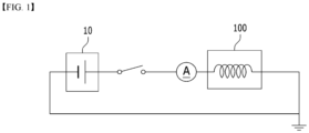
- Fig. 1 is a schematic diagram which shows a circuit of a battery pack according to an embodiment of the present disclosure.
- a battery pack may include a battery module 10 in which a plurality of battery cells are mounted; and a discharge member 100 electrically connected to the battery module 10.
- the battery module 10 is not specifically shown in the figure, but it may be configured such that a plurality of battery cells (not shown) are stacked in a predetermined direction and then mounted on a module frame (not shown).
- the plurality of the battery cells (not shown) is not particularly limited to the type thereof, and thus may be a pouch-type secondary battery or a prismatic secondary battery, but the pouch-type secondary battery is preferred.
- the battery cells (not shown) in the adjacent battery module 10 are discharged through the discharge member 100, which can suppress the temperature rise of the battery module 10.
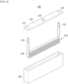
- Fig. 2 is an exploded perspective view of a discharge member included in the battery pack of Fig. 1 .
- Fig. 3 is a perspective view of the discharge member of Fig. 2 .
- the discharge member 100 includes a frame member 150 having an open upper portion and containing a coolant, an upper cover 170 for covering the upper portion of the frame member 150, and a resistor 110 mounted in the frame member 150, wherein both ends of the resistor 110 are exposed to the outside of the discharge member 100, and are electrically connected to the battery module 10.
- the frame member 150 and the upper cover 170 may be coupled to each other.
- the surfaces of the frame member 150 and the upper cover 170 that contact each other may be coupled together by a method such as welding.
- the present disclosure is not limited thereto, and any method that can stably couple and fix the frame member 150 and the upper cover 170 to each other can be included in the present embodiment.
- the frame member 150 and the upper cover 170 may be made of a material such as plastic or metal. Thereby, the frame member 150 and the upper cover 170 are made of the above-mentioned material, and thus can minimize the influence from ignition or flame generated in a part of the battery modules 10 in the battery pack.
- the upper cover 170 may have a first hole 171 and a second hole 175 formed therein, respectively. More specifically, both ends of the resistor 110 mounted within the frame member 150 may be exposed to the outside through the first hole 171 and the second hole 175, respectively.
- the first hole 171 and the second hole 175 may have a size equal to or larger than the cross-sectional area of the resistor 110.
- first hole 171 and the second hole 175 may be respectively formed on both sides of the upper cover 170.
- the positions of the first hole 171 and the second hole 175 are not limited thereto, and the first hole 171 and the second hole 175 may be formed at various positions.
- the upper cover 170 may be formed with a third hole 179 that can be opened and closed.
- the discharge member 100 may be configured such that the coolant is injected into the frame member 150 through the third hole 179.
- the discharge member 100 may be configured that water vapor formed by heat generation of the resistor 110 is discharged through the third hole 179.
- the discharge member 100 may be configured such that a coolant is injected into the frame member 150 through the third hole 179, and then seal the third hole 179.
- the coolant may be a cooling water.
- the discharge member 100 may be configured such that the third hole 179 is opened when the resistor 110 generates heat.
- the third hole 179 may be normally sealed. However, when resistance heat generation occurs in the resistor 110 in the frame member 150, the third hole 179 may be opened, and water vapor generated by resistance heat generation of the resistor 110 may be discharged to the outside of the discharge member 100.
- the third hole 179 may be formed in the central portion of the upper cover 170.
- the third hole 179 may be located between the first hole 171 and the second hole 175.
- the position of the third hole 179 is not limited thereto, and the third hole 179 may be formed at various positions.
- the third hole 179 may be opened and closed in some cases, which may have an advantage that the sealing property of the discharge member 100 can be improved and the safety can also be improved.
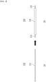
- Fig. 4 is a diagram which shows a resistor included in the discharge member of Fig. 2 .
- the resistor 110 may include a busbar 111 and an insulating layer 119. More specifically, on the outer surface of the busbar 111 extending in one direction as shown in Fig. 4(a) , an insulating layer 119 may be formed as shown in Fig. 4(b) .
- the central portion of the resistor 110 is formed with an insulating layer 119 on the outer surface of the busbar 111, and the end of the resistor 110 may be formed with power connection parts 113 and 115 in which the outer surface of the busbar 111 is exposed.
- the power connection parts 113 and 115 may be electrically connected to the battery module, respectively.
- the busbar 111 and the coolant inside the frame member 150 do not make direct contact with each other, thereby capable of preventing the occurrence of a short phenomenon between the busbar 111 and the coolant.
- the insulating layer 119 may be made of a material such as general rubber, silicone, or tape.
- the present disclosure is not limited thereto, and any material capable of preventing a short phenomenon between the coolant in the frame member 150 and the resistor 110 can be included in the present embodiment.
- the central portion of the resistor 110 may be located in the frame member 150, but may be submerged in the coolant contained within the frame member 150. More specifically, the resistor 110 may be submerged in the coolant contained within the frame member 150 except for the power connection parts 113 and 115.
- the central portion of the resistor 110 is submerged in the coolant in the frame member 150, so that heat occurred by resistance heat generation in the resistor 110 may be cooled by the coolant. That is, even when resistance heat generation occurs in the resistor 110, the resistor 110 is cooled by the coolant, so that the energization performance of the resistor 110 and the discharge performance of the battery module 10 can be improved.
- the resistor 110 can be bent at least twice in the frame member 150. More specifically, the resistor 110 can be bent multiple times in accordance with the size corresponding to the internal size of the frame member 150. Here, the resistor 110 can be bent multiple times in an S-shape. As an example, the resistor 110 can be a flexible busbar.
- the discharge member 100 includes the resistor 110 having a small cross-sectional area, but can include the resistor 110 having a relatively long length, thereby providing the advantage of having a compact size while reducing the resistance of the resistor 110.
- the busbar 111 included in the resistor 110 may be made of copper (Cu) having a resistance of 3 m ⁇ or more to 50 m ⁇ or less. More specifically, the busbar 111 may be made of copper (Cu) having a resistance of 3.5 m ⁇ or more to 47.5 m ⁇ or less. As an example, the busbar 111 may be made of copper (Cu) having a resistance of 4 m ⁇ or more and 45 mS2 or less.
- the resistor 110 includes a busbar 111 made of copper having a resistance in the above-mentioned range, and thus can sufficiently secure the energization performance while maintaining a compact size.
- the resistor 110 includes the busbar 111 made of copper having a resistance of less than 3 mQ, there is a problem that the resistance value is very small and thus the manufacturing process is not easy.
- the resistor 110 includes a busbar 111 made of copper having a resistance of more than 50 mQ, there is a problem that the discharge speed may be too slow, and as the size of the resistor 110 becomes relatively large, the space efficiency of the discharge member 100 is reduced.
- Fig. 5 is a diagram which shows a connection method of the discharge member of Fig. 2 .
- the discharge member 100 may include a first discharge member and a second discharge member, and the first discharge member and the second discharge member may be connected to each other in parallel.
- the discharge member 100 may realize a lower resistance than the resistance of the resistor 110 included in each discharge member 100 by connecting at least two discharge members in parallel.
- the discharge member 100 may include a first discharge member and a second discharge member, and the first discharge member and the second discharge member may be connected in series with each other.
- the discharge member 100 may realize a higher resistance than the resistance of the resistor 110 included in each discharge member 100 by connecting at least two discharge members in series.
- the discharge member 100 may be expanded in a parallel or series manner depending on the degree of discharging of the battery module 10, which has an advantage that the configuration of the resistance value of the discharge member 100 can be adjusted in various ways.
- Fig. 6 is a diagram which shows a discharge member according to another embodiment of the present disclosure.
- the discharge member 200 may be described in the same manner as the discharge member 100 of Fig. 2 , and only the resistor 210 will be further described.
- the resistor 110 of Fig. 2 is described as a first resistor 110
- the resistor 210 of Fig. 6 is described as a second resistor 210.
- the cross-sectional areas of the busbars included in the second resistor 210 and the first resistor 110 may be the same, but the lengths of the first resistor 110 and the second resistor 210 may be different.
- the cross-sectional areas of the busbar included in the second resistor 210 and the first resistor 110 may be the same, but the length of the second resistor 210 may be longer than the length of the first resistor 110.
- the resistors 110 and 210 can adjust the length of resistors 110 and 210 and the cross-sectional area of the busbar included therein in accordance with a target resistance value.
- the resistors 110 and 210 may be bent relatively few or many times in accordance with the size corresponding to the internal size of the frame member 150.
- the first resistor 110 may include a busbar having the same cross-sectional area, but the length of the resistor 110 may be relatively reduced to have a relatively smaller resistance value than that of the second resistor 210. At this time, when comparing Figs. 2 and 6 , the first resistor 110 is bent less often than the second resistor 210. Thereby, the first resistor 110 may have a relatively low resistance value, and thus a discharge speed may be relatively fast.
- the second resistor 210 may include a busbar having the same cross-sectional area, but the length of the resistor 210 may relatively increase and thus have a relatively larger resistance value than that of the first resistor 110. At this time, when comparing Figs. 2 and 6 , the second resistor 210 is bent more times than the first resistor 110. Thereby, the second resistor 210 may have a relatively high resistance value, and thus a discharge speed may be relatively slow.
- the discharge member 100 can adjust the length of the busbar 111 and thus adjust the resistance of the resistor 110, if necessary. That is, the discharge member 100 can relatively easily adjust the resistance of the resistor 110, which thus has an advantage that the discharge time according to the capacity of the battery and the discharge performance of the discharge member 100 required in various environments can be easily adjusted.
- a device may include the battery pack described above.
- a vehicle means such as an electric bicycle, an electric vehicle, or a hybrid vehicle, but the present disclosure is not limited thereto, and is applicable to various devices that can use a battery module and a battery pack including the same, which is also falls within the scope of the present disclosure.
Landscapes
- Engineering & Computer Science (AREA)
- Chemical & Material Sciences (AREA)
- Chemical Kinetics & Catalysis (AREA)
- Electrochemistry (AREA)
- General Chemical & Material Sciences (AREA)
- Manufacturing & Machinery (AREA)
- Microelectronics & Electronic Packaging (AREA)
- Power Engineering (AREA)
- Battery Mounting, Suspending (AREA)
- Connection Of Batteries Or Terminals (AREA)
Abstract
Description
- This application claims the benefit of
Korean Patent Application No. 10-2021-0056634 filed on April 30, 2021 - The present disclosure relates to a battery pack and a device including the same, and more particularly, to a battery pack that prevents self-heat generation of the battery module and a device including the same.
- Along with the technology development and increased demand for mobile devices, demand for secondary batteries as energy sources has been increasing rapidly. In particular, a secondary battery has attracted considerable attention as an energy source for power-driven devices, such as an electric bicycle, an electric vehicle, and a hybrid electric vehicle, as well as an energy source for mobile devices, such as a mobile phone, a digital camera, a laptop computer and a wearable device.
- Small-sized mobile devices use one or several battery cells for each device, whereas middle or large-sized devices such as vehicles require high power and large capacity. Therefore, a middle or large-sized battery module having a plurality of battery cells electrically connected to one another is used.
- The middle or large-sized battery module is preferably manufactured so as to have as small a size and weight as possible. Consequently, a prismatic battery, a pouch-shaped battery or the like, which can be stacked with high integration and has a small weight relative to capacity, is mainly used as a battery cell of the middle or large-sized battery module.
- However, the battery pack of the conventional technique includes a plurality of battery modules, and if a thermal runaway occurs in a part of the battery cells of each battery module to cause ignition or explosion, heat or flame may be transferred to the adjacent secondary battery to cause a secondary explosion or the like. Therefore, more efforts are being made to prevent secondary ignition or explosion.
- Therefore, there is a need to develop a battery pack and a device including the same which can prevent heat generation of a battery module on a heat transfer path when heat is transferred to adjacent battery modules at the time of ignition or explosion in a part of the battery modules in the battery pack.
- It is an object of the present disclosure to provide a battery pack that prevents self-heat generation of the battery module and a device including the same.
- The objects of the present disclosure are not limited to the aforementioned objects, and other objects which are not described herein should be clearly understood by those skilled in the art from the following detailed description and the accompanying drawings.
- According to one embodiment of the present disclosure, there is provided a battery pack comprising: a battery module in which a plurality of battery cells are mounted; and a discharge member electrically connected to the battery module, wherein the discharge member comprises a frame member having an open upper portion and containing a coolant, an upper cover for covering the upper portion of the frame member, and a resistor mounted in the frame member, wherein both ends of the resistor are exposed to the outside of the discharge member, and are electrically connected to the battery module.
- The resistor may be bent at least twice in the frame member.
- The resistor includes a busbar and an insulating layer, and the insulating layer may be formed on an outer surface of the busbar.
- The central portion of the resistor may be formed with an insulating layer on the outer surface of the busbar, and an end of the resistor may be formed with a power connection part to which an outer surface of the busbar is exposed.
- The busbar may be made of copper (Cu) having a resistance of 3 mQ or more to 50 mS2 or less.
- The upper cover may have a first hole and a second hole formed therein, respectively, and
both ends of the resistor pass through the first hole and the second hole, respectively, and are exposed to the outside. - The first hole and the second hole may be respectively formed on both sides of the upper cover.
- The upper cover may be formed with a third hole that can be opened and closed.
- The discharge member may be configured such that the coolant is injected into the frame member through a third hole.
- The discharge member may be configured such that water vapor formed by heat generation of the resistor is discharged through the third hole.
- The coolant may be a cooling water.
- The discharge member includes a first discharge member and a second discharge member, and the first discharge member and the second discharge member may be connected to each other in parallel.
- The discharge member includes a first discharge member and a second discharge member, and the first discharge member and the second discharge member may be connected to each other in series.
- According to another embodiment of the present disclosure, there is provided a device comprising the above-mentioned battery pack.
- According to embodiments, a battery pack and a device including the same of the present disclosure includes a discharge member electrically connected to the battery module and thus can prevent self-heat generation of the battery module.
- The effects of the present disclosure are not limited to the effects mentioned above and additional other effects not described above will be clearly understood from the description of the appended claims by those skilled in the art.
-
-
Fig. 1 is a schematic diagram which shows a circuit of a battery pack according to an embodiment of the present disclosure; -
Fig. 2 is an exploded perspective view of a discharge member included in the battery pack ofFig. 1 ; -
Fig. 3 is a perspective view of the discharge member ofFig. 2 ; -
Fig. 4 is a diagram which shows a resistor included in the discharge member ofFig. 2 ; -
Fig. 5 is a diagram which shows a connection method of the discharge member ofFig. 2 ; and -
Fig. 6 is a diagram which shows a discharge member according to another embodiment of the present disclosure. - Hereinafter, various embodiments of the present disclosure will be described in detail with reference to the accompanying drawings so that those skilled in the art can easily carry out them. The present disclosure can be modified in various different ways, and is not limited to the embodiments set forth herein.
- Portions that are irrelevant to the description will be omitted to clearly describe the present disclosure, and like reference numerals designate like elements throughout the description.
- Further, in the drawings, the size and thickness of each element are arbitrarily illustrated for convenience of description, and the present disclosure is not necessarily limited to those illustrated in the drawings. In the drawings, the thickness of layers, regions, etc. are exaggerated for clarity. In the drawings, for convenience of description, the thicknesses of some layers and regions are exaggerated.
- Further, throughout the description, when a portion is referred to as "including" or "comprising" a certain component, it means that the portion can further include other components, without excluding the other components, unless otherwise stated.
- Further, throughout the description, when referred to as "planar", it means when a target portion is viewed from the upper side, and when referred to as "cross-sectional", it means when a target portion is viewed from the side of a cross section cut vertically.
-
Fig. 1 is a schematic diagram which shows a circuit of a battery pack according to an embodiment of the present disclosure. - Referring to
Fig. 1 , a battery pack according to an embodiment of the present disclosure may include abattery module 10 in which a plurality of battery cells are mounted; and adischarge member 100 electrically connected to thebattery module 10. - Here, the
battery module 10 is not specifically shown in the figure, but it may be configured such that a plurality of battery cells (not shown) are stacked in a predetermined direction and then mounted on a module frame (not shown). Here, the plurality of the battery cells (not shown) is not particularly limited to the type thereof, and thus may be a pouch-type secondary battery or a prismatic secondary battery, but the pouch-type secondary battery is preferred. - Thereby, in the present embodiment, when a part of battery modules ignite or explode, the battery cells (not shown) in the
adjacent battery module 10 are discharged through thedischarge member 100, which can suppress the temperature rise of thebattery module 10. - Below, the
discharge member 100 will be described in more detail. -
Fig. 2 is an exploded perspective view of a discharge member included in the battery pack ofFig. 1 .Fig. 3 is a perspective view of the discharge member ofFig. 2 . - Referring to
Figs. 2 and3 , in one embodiment of the present disclosure, thedischarge member 100 includes aframe member 150 having an open upper portion and containing a coolant, anupper cover 170 for covering the upper portion of theframe member 150, and aresistor 110 mounted in theframe member 150, wherein both ends of theresistor 110 are exposed to the outside of thedischarge member 100, and are electrically connected to thebattery module 10. - Here, the
frame member 150 and theupper cover 170 may be coupled to each other. As an example, the surfaces of theframe member 150 and theupper cover 170 that contact each other may be coupled together by a method such as welding. However, the present disclosure is not limited thereto, and any method that can stably couple and fix theframe member 150 and theupper cover 170 to each other can be included in the present embodiment. - As an example, the
frame member 150 and theupper cover 170 may be made of a material such as plastic or metal. Thereby, theframe member 150 and theupper cover 170 are made of the above-mentioned material, and thus can minimize the influence from ignition or flame generated in a part of thebattery modules 10 in the battery pack. - Further, the
upper cover 170 may have afirst hole 171 and asecond hole 175 formed therein, respectively. More specifically, both ends of theresistor 110 mounted within theframe member 150 may be exposed to the outside through thefirst hole 171 and thesecond hole 175, respectively. Here, thefirst hole 171 and thesecond hole 175 may have a size equal to or larger than the cross-sectional area of theresistor 110. - As an example, the
first hole 171 and thesecond hole 175 may be respectively formed on both sides of theupper cover 170. However, the positions of thefirst hole 171 and thesecond hole 175 are not limited thereto, and thefirst hole 171 and thesecond hole 175 may be formed at various positions. - Thereby, in the
discharge member 100, both ends of theresistor 110 are exposed to the outside through thefirst hole 171 and thesecond hole 175, respectively, whereby thedischarge member 100 can be easily electrically connected to thebattery module 10. In addition, theupper cover 170 may be formed with athird hole 179 that can be opened and closed. Here, thedischarge member 100 may be configured such that the coolant is injected into theframe member 150 through thethird hole 179. Thedischarge member 100 may be configured that water vapor formed by heat generation of theresistor 110 is discharged through thethird hole 179. More specifically, thedischarge member 100 may be configured such that a coolant is injected into theframe member 150 through thethird hole 179, and then seal thethird hole 179. As an example, the coolant may be a cooling water. Further, thedischarge member 100 may be configured such that thethird hole 179 is opened when theresistor 110 generates heat. - In other words, after the coolant is injected through the
third hole 179 of theupper cover 170, thethird hole 179 may be normally sealed. However, when resistance heat generation occurs in theresistor 110 in theframe member 150, thethird hole 179 may be opened, and water vapor generated by resistance heat generation of theresistor 110 may be discharged to the outside of thedischarge member 100. - As an example, the
third hole 179 may be formed in the central portion of theupper cover 170. In other words, thethird hole 179 may be located between thefirst hole 171 and thesecond hole 175. However, the position of thethird hole 179 is not limited thereto, and thethird hole 179 may be formed at various positions. - Thereby, in the
discharge member 100, thethird hole 179 may be opened and closed in some cases, which may have an advantage that the sealing property of thedischarge member 100 can be improved and the safety can also be improved. -
Fig. 4 is a diagram which shows a resistor included in the discharge member ofFig. 2 . - Referring to
Fig. 4 , theresistor 110 may include abusbar 111 and an insulatinglayer 119. More specifically, on the outer surface of thebusbar 111 extending in one direction as shown inFig. 4(a) , an insulatinglayer 119 may be formed as shown inFig. 4(b) . - Here, the central portion of the
resistor 110 is formed with an insulatinglayer 119 on the outer surface of thebusbar 111, and the end of theresistor 110 may be formed withpower connection parts busbar 111 is exposed. In addition, thepower connection parts - Thereby, in the present embodiment, due to the insulating
layer 119 formed on the outer surface of theresistor 110, thebusbar 111 and the coolant inside theframe member 150 do not make direct contact with each other, thereby capable of preventing the occurrence of a short phenomenon between thebusbar 111 and the coolant. - As an example, the insulating
layer 119 may be made of a material such as general rubber, silicone, or tape. However, the present disclosure is not limited thereto, and any material capable of preventing a short phenomenon between the coolant in theframe member 150 and theresistor 110 can be included in the present embodiment. - Further, the central portion of the
resistor 110 may be located in theframe member 150, but may be submerged in the coolant contained within theframe member 150. More specifically, theresistor 110 may be submerged in the coolant contained within theframe member 150 except for thepower connection parts - Thereby, the central portion of the
resistor 110 is submerged in the coolant in theframe member 150, so that heat occurred by resistance heat generation in theresistor 110 may be cooled by the coolant. That is, even when resistance heat generation occurs in theresistor 110, theresistor 110 is cooled by the coolant, so that the energization performance of theresistor 110 and the discharge performance of thebattery module 10 can be improved. - Referring to
Figs. 3 and4 , theresistor 110 can be bent at least twice in theframe member 150. More specifically, theresistor 110 can be bent multiple times in accordance with the size corresponding to the internal size of theframe member 150. Here, theresistor 110 can be bent multiple times in an S-shape. As an example, theresistor 110 can be a flexible busbar. - Thereby, in the present embodiment, the
discharge member 100 includes theresistor 110 having a small cross-sectional area, but can include theresistor 110 having a relatively long length, thereby providing the advantage of having a compact size while reducing the resistance of theresistor 110. - Further, the
busbar 111 included in theresistor 110 may be made of copper (Cu) having a resistance of 3 mΩ or more to 50 mΩ or less. More specifically, thebusbar 111 may be made of copper (Cu) having a resistance of 3.5 mΩ or more to 47.5 mΩ or less. As an example, thebusbar 111 may be made of copper (Cu) having a resistance of 4 mΩ or more and 45 mS2 or less. - Thereby, the
resistor 110 includes abusbar 111 made of copper having a resistance in the above-mentioned range, and thus can sufficiently secure the energization performance while maintaining a compact size. - Unlike the same, when the
resistor 110 includes thebusbar 111 made of copper having a resistance of less than 3 mQ, there is a problem that the resistance value is very small and thus the manufacturing process is not easy. In addition, when theresistor 110 includes abusbar 111 made of copper having a resistance of more than 50 mQ, there is a problem that the discharge speed may be too slow, and as the size of theresistor 110 becomes relatively large, the space efficiency of thedischarge member 100 is reduced. -
Fig. 5 is a diagram which shows a connection method of the discharge member ofFig. 2 . - Referring to
Fig. 5(a) , thedischarge member 100 may include a first discharge member and a second discharge member, and the first discharge member and the second discharge member may be connected to each other in parallel. - Thereby, the
discharge member 100 may realize a lower resistance than the resistance of theresistor 110 included in eachdischarge member 100 by connecting at least two discharge members in parallel. - Further, referring to
Fig. 5b , thedischarge member 100 may include a first discharge member and a second discharge member, and the first discharge member and the second discharge member may be connected in series with each other. - Thereby, the
discharge member 100 may realize a higher resistance than the resistance of theresistor 110 included in eachdischarge member 100 by connecting at least two discharge members in series. - By the above configuration, in the present embodiment, the
discharge member 100 may be expanded in a parallel or series manner depending on the degree of discharging of thebattery module 10, which has an advantage that the configuration of the resistance value of thedischarge member 100 can be adjusted in various ways. -
Fig. 6 is a diagram which shows a discharge member according to another embodiment of the present disclosure. - Referring to
Figs. 2 and6 , thedischarge member 200 according to the present embodiment may be described in the same manner as thedischarge member 100 ofFig. 2 , and only theresistor 210 will be further described. Here, theresistor 110 ofFig. 2 is described as afirst resistor 110, and theresistor 210 ofFig. 6 is described as asecond resistor 210. - Here, the cross-sectional areas of the busbars included in the
second resistor 210 and thefirst resistor 110 may be the same, but the lengths of thefirst resistor 110 and thesecond resistor 210 may be different. As an example, the cross-sectional areas of the busbar included in thesecond resistor 210 and thefirst resistor 110 may be the same, but the length of thesecond resistor 210 may be longer than the length of thefirst resistor 110. - In this manner, referring to
Figs. 2 and6 , theresistors resistors resistors frame member 150. - More specifically, the
first resistor 110 may include a busbar having the same cross-sectional area, but the length of theresistor 110 may be relatively reduced to have a relatively smaller resistance value than that of thesecond resistor 210. At this time, when comparingFigs. 2 and6 , thefirst resistor 110 is bent less often than thesecond resistor 210. Thereby, thefirst resistor 110 may have a relatively low resistance value, and thus a discharge speed may be relatively fast. - Further, the
second resistor 210 may include a busbar having the same cross-sectional area, but the length of theresistor 210 may relatively increase and thus have a relatively larger resistance value than that of thefirst resistor 110. At this time, when comparingFigs. 2 and6 , thesecond resistor 210 is bent more times than thefirst resistor 110. Thereby, thesecond resistor 210 may have a relatively high resistance value, and thus a discharge speed may be relatively slow. - Thereby, in the present embodiment, the
discharge member 100 can adjust the length of thebusbar 111 and thus adjust the resistance of theresistor 110, if necessary. That is, thedischarge member 100 can relatively easily adjust the resistance of theresistor 110, which thus has an advantage that the discharge time according to the capacity of the battery and the discharge performance of thedischarge member 100 required in various environments can be easily adjusted. - Meanwhile, a device according to another embodiment of the present disclosure may include the battery pack described above. Such a device can be applied to a vehicle means such as an electric bicycle, an electric vehicle, or a hybrid vehicle, but the present disclosure is not limited thereto, and is applicable to various devices that can use a battery module and a battery pack including the same, which is also falls within the scope of the present disclosure.
- Although preferred embodiments of the present disclosure have been described in detail above, the scope of the present disclosure is not limited thereto, and various modifications and improvements made by those skilled in the art using the basic concepts of the present disclosure, which are defined in the appended claims, also falls within the scope of the present disclosure.
-
- 10: battery module
- 100: discharge member
- 110: register
- 150: frame member
- 170: upper cover
Claims (14)
- A battery pack comprising:a battery module in which a plurality of battery cells are mounted; anda discharge member electrically connected to the battery module,wherein the discharge member comprises,a frame member having an open upper portion and containing a coolant,an upper cover for covering the upper portion of the frame member, anda resistor mounted in the frame member,wherein both ends of the resistor are exposed to the outside of the discharge member, and are electrically connected to the battery module.
- The battery pack according to claim 1, wherein:
the resistor is bent at least twice in the frame member. - The battery pack according to claim 2, wherein:the resistor includes a busbar and an insulating layer, andthe insulating layer is formed on an outer surface of the busbar.
- The battery pack according to claim 3, wherein:the central portion of the resistor is formed with an insulating layer on the outer surface of the busbar, andan end of the resistor is formed with a power connection part to which an outer surface of the busbar is exposed.
- The battery pack according to claim 3, wherein:
the busbar is made of copper (Cu) having a resistance of 3 mΩ or more to 50 mΩ or less. - The battery pack according to claim 1, wherein:the upper cover has a first hole and a second hole formed therein, respectively, andboth ends of the resistor pass through the first hole and the second hole, respectively, and are exposed to the outside.
- The battery pack according to claim 6, wherein:
the first hole and the second hole are respectively formed on both sides of the upper cover. - The battery pack according to claim 1, wherein:
the upper cover is formed with a third hole that can be opened and closed. - The battery pack according to claim 8, wherein:
the discharge member is configured such that the coolant is injected into the frame member through a third hole. - The battery pack according to claim 9, wherein:
the discharge member is configured such that water vapor formed by heat generation of the resistor is discharged through the third hole. - The battery pack according to claim 9, wherein:
the coolant is a cooling water. - The battery pack according to claim 1, wherein:the discharge member includes a first discharge member and a second discharge member, andthe first discharge member and the second discharge member are connected to each other in parallel.
- The battery pack according to claim 1, wherein:the discharge member includes a first discharge member and a second discharge member, andthe first discharge member and the second discharge member are connected to each other in series.
- A device comprising the battery pack according to claim 1.
Applications Claiming Priority (2)
| Application Number | Priority Date | Filing Date | Title |
|---|---|---|---|
| KR1020210056634A KR20220149249A (en) | 2021-04-30 | 2021-04-30 | Battery pack and device including the same |
| PCT/KR2022/004762 WO2022231152A1 (en) | 2021-04-30 | 2022-04-04 | Battery pack and device including same |
Publications (2)
| Publication Number | Publication Date |
|---|---|
| EP4175008A1 true EP4175008A1 (en) | 2023-05-03 |
| EP4175008A4 EP4175008A4 (en) | 2024-02-21 |
Family
ID=83846998
Family Applications (1)
| Application Number | Title | Priority Date | Filing Date |
|---|---|---|---|
| EP22795986.3A Pending EP4175008A4 (en) | 2021-04-30 | 2022-04-04 | Battery pack and device including same |
Country Status (6)
| Country | Link |
|---|---|
| US (1) | US12555877B2 (en) |
| EP (1) | EP4175008A4 (en) |
| JP (1) | JP7578375B2 (en) |
| KR (1) | KR20220149249A (en) |
| CN (1) | CN115943514B (en) |
| WO (1) | WO2022231152A1 (en) |
Families Citing this family (1)
| Publication number | Priority date | Publication date | Assignee | Title |
|---|---|---|---|---|
| US20250373062A1 (en) * | 2024-05-31 | 2025-12-04 | Cox Automotive, Inc. | System and methods for discharging a battery |
Family Cites Families (29)
| Publication number | Priority date | Publication date | Assignee | Title |
|---|---|---|---|---|
| DE2414758B2 (en) | 1974-03-27 | 1976-04-15 | Varta Batterie Ag, 3000 Hannover | ELECTROLYTE COOLING DEVICE FOR ACCUMULATOR BATTERIES CONSISTING OF MULTIPLE CELLS |
| JP3111276B2 (en) * | 1997-11-29 | 2000-11-20 | 幹三 笠松 | Secondary battery explosion prevention device |
| WO2008079062A1 (en) | 2006-12-22 | 2008-07-03 | Volvo Technology Corporation | Method and arrangement for discharging an energy storage system for electrical energy |
| JP2011023179A (en) * | 2009-07-14 | 2011-02-03 | Sanyo Electric Co Ltd | Battery pack, vehicle equipped therewith, and bus bar for battery pack |
| GB2478547B (en) * | 2010-03-09 | 2014-01-15 | Cressall Resistors Ltd | Liquid-cooled brake resistor for use in electric vehicles |
| FR2961640B1 (en) * | 2010-06-18 | 2019-08-02 | Psa Automobiles Sa. | POWER BATTERY MODULE |
| DE102010064596B3 (en) * | 2010-12-22 | 2015-11-12 | Reo Inductive Components Ag | resistor arrangement |
| US20130089755A1 (en) | 2011-10-11 | 2013-04-11 | In-Soo Park | Battery Pack |
| ES2640640T3 (en) * | 2011-11-14 | 2017-11-03 | Cressall Resistors Limited | Liquid cooled resistance device |
| JP2014062826A (en) | 2012-09-21 | 2014-04-10 | Furukawa Electric Co Ltd:The | Battery internal resistance measurement device |
| KR101749721B1 (en) | 2014-04-04 | 2017-06-21 | 주식회사 엘지화학 | Battery Module Assembly Having Fuse Assembly |
| TWI493770B (en) | 2014-04-21 | 2015-07-21 | Energy Control Ltd | Secondary assembled battery with overcharge and discharge device |
| US11075048B2 (en) | 2014-05-28 | 2021-07-27 | Eaton Intelligent Power Limited | Compact high voltage power fuse and methods of manufacture |
| US11075047B2 (en) | 2014-05-28 | 2021-07-27 | Eaton Intelligent Power Limited | Compact high voltage power fuse and methods of manufacture |
| EP3123554B1 (en) | 2014-06-30 | 2021-06-23 | BYD Company Limited | Battery heating system, battery assembly and electric vehicle |
| FR3023364B1 (en) | 2014-07-03 | 2016-08-19 | Valeo Systemes Thermiques | DUAL CIRCULATION THERMAL EXCHANGER AND CORRESPONDING THERMAL MANAGEMENT INSTALLATION |
| KR101780037B1 (en) | 2015-04-22 | 2017-09-19 | 주식회사 엘지화학 | Cooling device for battery cell and battery module comprising the same |
| US9941036B2 (en) * | 2016-02-02 | 2018-04-10 | Raytheon Company | Modular, high density, low inductance, media cooled resistor |
| KR102018719B1 (en) * | 2016-02-12 | 2019-09-04 | 주식회사 엘지화학 | Busbar for cooling battery cell and battery module using thereof |
| KR101887758B1 (en) | 2016-09-26 | 2018-08-10 | 현대자동차주식회사 | Battery module having overcharge prevention function |
| JP7009848B2 (en) * | 2017-09-05 | 2022-01-26 | 株式会社デンソー | Battery module |
| KR102450418B1 (en) | 2018-12-07 | 2022-09-30 | 주식회사 엘지에너지솔루션 | Battery module with improved safety, battery pack comprising the battery module and vehicle comprising the same |
| KR102751111B1 (en) | 2019-06-17 | 2025-01-06 | 주식회사 엘지에너지솔루션 | Battery Module Comprising Base Plate having Gas Discharge Passage and Battery Pack and Energy Storage System |
| KR102825906B1 (en) * | 2019-07-08 | 2025-06-26 | 주식회사 엘지에너지솔루션 | Battery Module System with External Shorting Device and Cooling Device |
| KR102709974B1 (en) * | 2019-07-10 | 2024-09-24 | 주식회사 엘지에너지솔루션 | Battery module, battery rack and energy storage system comprising the battery module |
| KR102808616B1 (en) * | 2019-07-15 | 2025-05-14 | 주식회사 엘지에너지솔루션 | Battery Module System Having External Shorting Device |
| KR102792385B1 (en) | 2019-10-18 | 2025-04-04 | 주식회사 엘지에너지솔루션 | Battery pack and vehicle comprising the battery pack |
| KR102339853B1 (en) | 2019-11-11 | 2021-12-16 | 부산대학교 산학협력단 | Lymphedema treatment device |
| KR20200141425A (en) | 2020-12-09 | 2020-12-18 | 도정국 | Rapid Discharge Apparatus and Discharge Method for EV(Electric Vehicle) Battery |
-
2021
- 2021-04-30 KR KR1020210056634A patent/KR20220149249A/en active Pending
-
2022
- 2022-04-04 WO PCT/KR2022/004762 patent/WO2022231152A1/en not_active Ceased
- 2022-04-04 US US18/019,749 patent/US12555877B2/en active Active
- 2022-04-04 EP EP22795986.3A patent/EP4175008A4/en active Pending
- 2022-04-04 JP JP2023504854A patent/JP7578375B2/en active Active
- 2022-04-04 CN CN202280005625.XA patent/CN115943514B/en active Active
Also Published As
| Publication number | Publication date |
|---|---|
| JP7578375B2 (en) | 2024-11-06 |
| CN115943514B (en) | 2026-03-06 |
| US20230291082A1 (en) | 2023-09-14 |
| EP4175008A4 (en) | 2024-02-21 |
| WO2022231152A1 (en) | 2022-11-03 |
| US12555877B2 (en) | 2026-02-17 |
| KR20220149249A (en) | 2022-11-08 |
| CN115943514A (en) | 2023-04-07 |
| JP2023535945A (en) | 2023-08-22 |
Similar Documents
| Publication | Publication Date | Title |
|---|---|---|
| CN114361677B (en) | Battery module and battery pack including the battery module | |
| US12155050B2 (en) | Battery module and battery pack including the same | |
| EP4120446B1 (en) | Secondary battery | |
| EP3961792A1 (en) | Battery module and battery pack including same | |
| EP4170779A1 (en) | Battery module and battery pack including same | |
| KR20230006086A (en) | Battery pack and device including the same | |
| US12555877B2 (en) | Battery pack and device including the same | |
| US12603384B2 (en) | Battery module and battery pack including the same | |
| WO2018180254A1 (en) | Battery pack | |
| US12315964B2 (en) | Battery module and battery pack including the same | |
| JP2023535774A (en) | Battery module and battery pack containing same | |
| US11942659B2 (en) | Battery module and battery pack including the same | |
| US12542311B2 (en) | Battery module and battery pack including the same | |
| EP4120441B1 (en) | Battery module and battery pack including the same | |
| US9887436B2 (en) | Battery pack | |
| EP4645531A1 (en) | Battery module and battery pack including same | |
| EP4625651A2 (en) | Cooling fin, battery module, battery pack and device including the same | |
| US20240387937A1 (en) | Battery device | |
| EP4712212A1 (en) | Cooling device and battery cell stack including same | |
| KR20230097704A (en) | Battery pack and device including the same | |
| EP4648181A1 (en) | Battery module and battery pack including same | |
| KR20260014282A (en) | Battery Cell, battery pack and vehicle including the same | |
| CN118104056A (en) | Secondary battery and battery module including the same | |
| KR20230097703A (en) | Heat dissipation member and battery pack including the same |
Legal Events
| Date | Code | Title | Description |
|---|---|---|---|
| STAA | Information on the status of an ep patent application or granted ep patent |
Free format text: STATUS: THE INTERNATIONAL PUBLICATION HAS BEEN MADE |
|
| PUAI | Public reference made under article 153(3) epc to a published international application that has entered the european phase |
Free format text: ORIGINAL CODE: 0009012 |
|
| STAA | Information on the status of an ep patent application or granted ep patent |
Free format text: STATUS: REQUEST FOR EXAMINATION WAS MADE |
|
| 17P | Request for examination filed |
Effective date: 20230125 |
|
| AK | Designated contracting states |
Kind code of ref document: A1 Designated state(s): AL AT BE BG CH CY CZ DE DK EE ES FI FR GB GR HR HU IE IS IT LI LT LU LV MC MK MT NL NO PL PT RO RS SE SI SK SM TR |
|
| REG | Reference to a national code |
Ref country code: DE Ref legal event code: R079 Free format text: PREVIOUS MAIN CLASS: H01M0010420000 Ipc: H01C0001080000 |
|
| A4 | Supplementary search report drawn up and despatched |
Effective date: 20240123 |
|
| RIC1 | Information provided on ipc code assigned before grant |
Ipc: H01C 1/082 20060101ALN20240117BHEP Ipc: H01G 11/82 20130101ALN20240117BHEP Ipc: H01G 11/10 20130101ALN20240117BHEP Ipc: H01M 10/613 20140101ALI20240117BHEP Ipc: H01G 11/18 20130101ALI20240117BHEP Ipc: H02J 7/00 20060101ALI20240117BHEP Ipc: H01M 10/667 20140101ALI20240117BHEP Ipc: H01M 10/44 20060101ALI20240117BHEP Ipc: H01M 10/42 20060101ALI20240117BHEP Ipc: H01C 3/14 20060101ALI20240117BHEP Ipc: H01C 3/06 20060101ALI20240117BHEP Ipc: H01C 3/10 20060101ALI20240117BHEP Ipc: H01C 1/08 20060101AFI20240117BHEP |
|
| DAV | Request for validation of the european patent (deleted) | ||
| DAX | Request for extension of the european patent (deleted) |