EP4174900B1 - Sealed inline fuse module - Google Patents
Sealed inline fuse module Download PDFInfo
- Publication number
- EP4174900B1 EP4174900B1 EP22197361.3A EP22197361A EP4174900B1 EP 4174900 B1 EP4174900 B1 EP 4174900B1 EP 22197361 A EP22197361 A EP 22197361A EP 4174900 B1 EP4174900 B1 EP 4174900B1
- Authority
- EP
- European Patent Office
- Prior art keywords
- fuse
- main body
- body portion
- hole
- bolt
- Prior art date
- Legal status (The legal status is an assumption and is not a legal conclusion. Google has not performed a legal analysis and makes no representation as to the accuracy of the status listed.)
- Active
Links
Images
Classifications
-
- H—ELECTRICITY
- H01—ELECTRIC ELEMENTS
- H01H—ELECTRIC SWITCHES; RELAYS; SELECTORS; EMERGENCY PROTECTIVE DEVICES
- H01H85/00—Protective devices in which the current flows through a part of fusible material and this current is interrupted by displacement of the fusible material when this current becomes excessive
- H01H85/02—Details
- H01H85/20—Bases for supporting the fuse; Separate parts thereof
-
- H—ELECTRICITY
- H01—ELECTRIC ELEMENTS
- H01H—ELECTRIC SWITCHES; RELAYS; SELECTORS; EMERGENCY PROTECTIVE DEVICES
- H01H85/00—Protective devices in which the current flows through a part of fusible material and this current is interrupted by displacement of the fusible material when this current becomes excessive
- H01H85/0013—Means for preventing damage, e.g. by ambient influences to the fuse
- H01H85/0021—Means for preventing damage, e.g. by ambient influences to the fuse water or dustproof devices
- H01H85/0026—Means for preventing damage, e.g. by ambient influences to the fuse water or dustproof devices casings for the fuse and its base contacts
-
- H—ELECTRICITY
- H01—ELECTRIC ELEMENTS
- H01H—ELECTRIC SWITCHES; RELAYS; SELECTORS; EMERGENCY PROTECTIVE DEVICES
- H01H85/00—Protective devices in which the current flows through a part of fusible material and this current is interrupted by displacement of the fusible material when this current becomes excessive
- H01H85/02—Details
- H01H85/04—Fuses, i.e. expendable parts of the protective device, e.g. cartridges
- H01H85/05—Component parts thereof
- H01H85/165—Casings
-
- H—ELECTRICITY
- H01—ELECTRIC ELEMENTS
- H01H—ELECTRIC SWITCHES; RELAYS; SELECTORS; EMERGENCY PROTECTIVE DEVICES
- H01H85/00—Protective devices in which the current flows through a part of fusible material and this current is interrupted by displacement of the fusible material when this current becomes excessive
- H01H85/02—Details
- H01H85/20—Bases for supporting the fuse; Separate parts thereof
- H01H85/2045—Mounting means or insulating parts of the base, e.g. covers, casings
-
- H—ELECTRICITY
- H01—ELECTRIC ELEMENTS
- H01R—ELECTRICALLY-CONDUCTIVE CONNECTIONS; STRUCTURAL ASSOCIATIONS OF A PLURALITY OF MUTUALLY-INSULATED ELECTRICAL CONNECTING ELEMENTS; COUPLING DEVICES; CURRENT COLLECTORS
- H01R11/00—Individual connecting elements providing two or more spaced connecting locations for conductive members which are, or may be, thereby interconnected, e.g. end pieces for wires or cables supported by the wire or cable and having means for facilitating electrical connection to some other wire, terminal, or conductive member, blocks of binding posts
- H01R11/11—End pieces or tapping pieces for wires, supported by the wire and for facilitating electrical connection to some other wire, terminal or conductive member
- H01R11/12—End pieces terminating in an eye, hook, or fork
-
- H—ELECTRICITY
- H01—ELECTRIC ELEMENTS
- H01H—ELECTRIC SWITCHES; RELAYS; SELECTORS; EMERGENCY PROTECTIVE DEVICES
- H01H85/00—Protective devices in which the current flows through a part of fusible material and this current is interrupted by displacement of the fusible material when this current becomes excessive
- H01H85/02—Details
- H01H85/20—Bases for supporting the fuse; Separate parts thereof
- H01H2085/209—Modular assembly of fuses or holders, e.g. side by side; combination of a plurality of identical fuse units
-
- H—ELECTRICITY
- H02—GENERATION; CONVERSION OR DISTRIBUTION OF ELECTRIC POWER
- H02G—INSTALLATION OF ELECTRIC CABLES OR LINES, OR OF COMBINED OPTICAL AND ELECTRIC CABLES OR LINES
- H02G15/00—Cable fittings
- H02G15/08—Cable junctions
- H02G15/10—Cable junctions protected by boxes, e.g. by distribution, connection or junction boxes
- H02G15/115—Boxes split perpendicularly to main cable direction
Definitions
- the disclosure relates generally to the field of circuit protection devices and relates more particularly to a sealed inline fuse module.
- Fuse modules are sometimes implemented in vehicular applications.
- a fuse module is mounted directly to source of electrical power (e.g., a battery) to and is connected electrically in series between the source and a connected load.
- source of electrical power e.g., a battery
- a fusible element within the fuse module melts, disintegrates, or otherwise opens to arrest the flow of current through the fuse module.
- the fuse module thereby prevents or mitigates electrical damage to the electrical source and/or the load that would otherwise result if the overcurrent condition were allowed to persist.
- a fuse module it may be desirable to implement a fuse module at a location distant from an electrical source, in series between the source and a load. It may further be desirable for such a fuse module to be fluidically sealed from its environment. It may further be desirable for such a fuse module to have a fuse that is easily removable and replaceable.
- a fuse box having a housing formed with a first, second, and third openings therein.
- a screw-fastened type fuse having two terminals is inserted into the housing through the second opening.
- Conductors connected to the fuse are directed to external circuits through the first opening.
- the third openings oppose the terminals of the fuse inserted and have guide grooves.
- Each of the terminals is connected together with the conductors to the housing by means of a bolt inserted through the third opening.
- a cover is attached to the second opening after the terminals of fuse are securely connected to the housing together with the conductors.
- the cover is formed with a lid continuously integral with the cover and the lid is accepted and guided by the guide grooves to close the third opening when the cover is assembled to the housing.
- EP3671801A1 discloses a sealed battery fuse, for a fuse with a through-hole. Junction boxes holding a fuse are disclosed in US2017345604A1 and DE202004000526U1 . A molded inline fuse holder with a cap attached to the main body via a lid is known from USD414749S.
- An exemplary embodiment of a fuse module in accordance with an embodiment of the present disclosure may include a fuse holder as defined in claim 1.
- the fuse module may further include a fuse disposed within the fuse holder, the fuse having a mounting block formed of an electrically insulating material and having a through-hole extending therethrough, the through hole of the mounting block being aligned with the first and second through holes in the rear and front walls of the main body portion, and a fuse plate having a rear portion disposed on a rear surface of the mounting block, in contact with the first ring terminal, and having a first through hole aligned with the through hole of the mounting block, a front portion disposed on a front surface of the mounting block, in contact with the second ring terminal, and having a second through hole aligned with the through-hole of the mounting block, and a fusible element disposed adjacent a top surface of the mounting block and connecting the rear portion of the fuse plate to the front portion of the fuse plate.
- the fuse module may further include a bolt extending through the front wall, the second ring terminal, the front portion of the fuse plate, the mounting block, the rear portion of the fuse plate, the first ring terminal, and the rear wall, the bolt secured by a nut on the exterior of the rear wall.
- An exemplary embodiment of a fuse holder in accordance with the present disclosure may include a main body portion formed of an electrically insulating material, the main body portion defining a hollow interior and having first and second through holes formed in opposing rear and front walls thereof, respectively, the first and second through holes being aligned with one another, an integrated first electrical cable having a first ring terminal extending into the hollow interior of the main body portion, the first ring terminal disposed on the rear wall and aligned with the first through hole in the rear wall, and an integrated second electrical cable having a second ring terminal extending into the hollow interior of the main body portion, the second ring terminal disposed on the front wall and aligned with the second through hole in the front wall, wherein the main body portion (30) is overmolded onto the first and second electrical cables (15a, 15b) and the first and second ring terminals (38a, 38b) are recessed within, and have exposed surfaces that are coplanar with interior surfaces of the rear and front walls (40a, 40b) of the main body portion.
- a fuse module in accordance with the present disclosure will now be described more fully with reference to the accompanying drawings, in which preferred embodiments of the fuse module are presented. It will be understood, however, that the fuse module may be embodied in many different forms and should not be construed as being limited to the embodiments set forth herein. Rather, these embodiments are provided so that this disclosure will convey certain exemplary aspects of the fuse module to those skilled in the art.
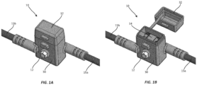
- FIG. 1A and 1B perspective views illustrating a fuse module 10 in accordance with an exemplary, non-limiting embodiment of the present disclosure is shown.
- terms such as “front,” “rear,” “top,” “bottom,” “side,” “above,” and “below” may be used herein to describe the relative placement and orientation of various components of the fuse module 10, all with respect to the geometry and orientation of the fuse module 10 as it appears in FIGS. 1A and 1B .
- Said terminology will include the words specifically mentioned, derivatives thereof, and words of similar import.
- the fuse module 10 includes a sealable, inline fuse holder 12 (hereinafter “the fuse holder 12") and a fuse 14 removably disposed within the fuse holder 12.
- the fuse holder 12 includes integrated first and second electrical cables 15a, 15b for connecting the fuse module 10 within an electrical circuit (e.g., electrically in series between a source of electrical power and a load) as described in greater detail below.
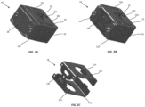
- the fuse 14 may include a mounting block 16 formed of an electrically insulating material, and a fuse plate 18 that extends around several surfaces of the mounting block 16.
- the fuse plate 18 (which is shown in isolation in FIG. 2C for clarity) may include a rear portion 18a disposed on a rear surface 16a of the mounting block 16, a front portion 18b disposed on a front surface 16b of the mounting block 16, opposite the rear surface 16a, and a fusible element 18c disposed on or adjacent a top surface 16c of the mounting block 16 and connecting the rear portion 18a to the front portion 18b.
- the mounting block 16 may include a through hole 20 extending between and through the rear surface 16a and the front surface 16b, and the rear and front portions 18a, 18b of the fuse plate 18 may include respective first and second through holes 22a, 22b that are aligned with the through hole 20 of the mounting block 16.
- the mounting block 16 may further include an insulating cover 26 (shown in FIG. 2A and omitted in FIG. 2B ) that fits over the fusible element 18c and attaches to the top surface 16c of the mounting block 16 (e.g., via snap fit, mechanical fasteners, etc.).
- the fusible element 18c may be configured to melt, disintegrate, or otherwise open if current flowing through fuse plate 18 exceeds a predetermined threshold, or "current rating," of the fuse 14.
- the fusible element 18c may include perforations, slots, thinned or narrowed segments, and/or various other features for making the fusible element 18c more susceptible to melting or opening than other portions of the fuse plate 18.
- the fusible element 18c may have a generally X-shaped configuration. The present disclosure is not limited in this regard.
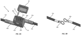
- the fuse holder 12 may be a substantially hollow body having the shape of a rectangular cuboid, and may include a main body portion 30 and a cap 32 removably couplable to the main body portion 30, such as via snap fit, friction fit, etc.
- the interior of the fuse holder 12 may define a fluidically sealed volume.
- the cap 32 may be connected to the main body portion 30 by a flexible, integrally formed lanyard 34.
- the present disclosure is not limited in this regard.
- the internal dimensions of the fuse holder 12 may be adapted to accommodate the fuse 14 in a close clearance relationship therewith as further described below.
- the fuse holder 12 may be formed of rubber or other resilient, electrically insulating material.
- the fuse holder 12 may further include integrally formed first and second electrical cable collars 36a, 36b extending from a rear edge and a front edge of the main body portion 30, respectively, for holding terminal ends of respective first and second electrical cables 15a, 15b.
- the first and second electrical cables 15a, 15b may be shielded and terminate in respective electrically conductive first and second ring terminals 38a, 38b (as best shown in the isolated view of the first and second electrical cables 15a, 15b in FIG. 3B ) that extend into the interior of the main body portion 30.
- the first and second ring terminals 38a, 38b are disposed in flat abutment with interior surfaces of rear and front walls 40a, 40b of the main body portion 30, respectively.
- the first and second ring terminals 38a, 38b are aligned with (e.g., concentric with) first and second through holes 42a, 42b formed in the rear and front walls 40a, 40b.
- the main body portion 30 is overmolded onto the first and second electrical cables 15a, 15b, and the first and second ring terminals 38a, 38b are recessed within, and have exposed surfaces that are coplanar with, the interior surfaces of the rear and front walls 40a, 40b of the main body portion 30.
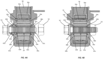
- FIGS. 4A and 4B cross-sectional views illustrating the fuse 14 disposed within the fuse holder 12 in unfastened and fastened states, respectively, are shown.
- the fuse 14 may be disposed within the main body portion 30, with the rear portion 18a of the fuse plate 18 disposed in flat abutment with the interior surface of the rear wall 40a and in direct contact with the first ring terminal 38a, and with the front portion 18b of the fuse plate 18 disposed in flat abutment with the interior surface of the front wall 40b and in direct contact with the second ring terminal 38b.
- the fusible element 18c and the cover 26 may face up, toward the open top of the main body portion 30.
- the present disclosure is not limited in this regard.
- the through hole 20 of the mounting block 16 may be aligned with (e.g., concentric with) the first and second ring terminals 38a, 38b and the first and second through holes 42a, 42b in the rear and front walls 40a, 40b of the main body portion 30.
- the main body portion 30 may include first and second annular lips 44a, 44b extending from the interior surfaces of the rear and front walls 40a, 40b around the first and second through holes 42a, 42b, respectively. Outer diameters of the first and second annular lips 44a, 44b may be smaller than diameters of the through holes 22a, 22b in the rear and front portions 18a, 18b of the fuse plate 18 and smaller than the diameter of the through hole 20 of the mounting block 16.
- the main body portion 30 may further include first and second annular raised portions 46a, 46b extending from the exterior surfaces of the rear and front walls 40a, 40b around the first and second through holes 42a, 42b, respectively.
- the first annular lip 44a and the first raised portion 46a may together define a first interior surface 48a of the first through hole 42a
- the second annular lip 44b and the second raised portion 46b may together define a second interior surface 48b of the second through hole 42b.
- the first and second interior surfaces 48a, 48b may be sloped or angled such that the first and second through holes 42a, 42b may be larger at the interior surfaces of the rear and front walls 40a, 40b and smaller at the exterior surfaces of the rear and front walls 40a, 40b.
- a bolt 50 may be inserted through each of the second through hole 42b in the front wall 40b of the main body portion 30, the second through hole 22b in the front portion 18b of the fuse plate 18, the through hole 20 in the mounting block 16, the first through hole 22a in the rear portion 18a of the fuse plate 18, and the first through hole 42a in the rear wall 40a of the main body portion 30 as shown in FIG. 4A .
- a nut 52 may then be tightened onto the protruding end of the bolt 50. As the nut 52 is tightened, the nut 52 and the head of the bolt 50 may bear against the first and second annular raised portions 46a, 46b and may compress the first and second annular raised portions 46a, 46b toward one another.
- the compression of the first and second annular raised portions 46a, 46b may cause the first and second annular lips 44a, 44b to be pressed into the annular gaps between the bolt 50 and the rear and front portions 18a, 18b of the fuse plate 18, respectively, as shown in FIG. 4B .
- the first and second annular lips 44a, 44b may thereby provide electrically insulating annular barriers between the bolt 50 and the fuse plate 18.
- the compression of the first and second annular raised portions 46a, 46b may cause the angled first and second interior surfaces 48a, 48b of the first and second through holes 42a, 42b to be pressed firmly against the bolt 50 to establish fluid-tight seals between the angled interior surfaces 48a, 48b and the bolt.
- the installation of the fuse 14 may be completed by fitting the cap 32 of the fuse holder 12 onto the main body portion 30 as shown in FIG. 1A .
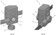
- an embodiment of the fuse module 10 is shown that includes removable bolt caps 56a, 56b for covering the nut 52 and the head of the bolt 50 (not within view).
- the bolt caps 56a, 56b may be beneficial for applications in which fluidic sealing of fuse holder 12 is a critical requirement.
- the bolt caps 56a, 56b may be integrally formed with the main body portion 30 of the fuse holder 12 (e.g., during molding of the main body portion 30) and may be couplable to annular flanges that are also integrally formed with the main body portion 30 and that surround the nut 52 and the head of the bolt 50, such as via friction fit, interference fit, etc.
- annular flange 58a on the rear wall 40a of the main body portion 30 is within view in FIG. 5A . It will be understood that a substantially identical annular flange is formed on the front wall 40b of the main body portion 30.
- the bolt caps 56a, 56b may be connected to the main body portion 30 by integrally formed lanyards as shown in FIG. 5A . Only one lanyard 60a extending from the rear of the main body portion 30 is within view in FIG. 5A . It will be understood that a substantially identical lanyard may connect the bolt cap 56b to the front of the main body portion 30. In various embodiments the lanyards may be omitted as in FIG. 5B .
- the first and second electrical cables 15a, 15b may be connected within an electrical circuit (e.g., to a battery and a load, respectively) and current may flow through the first and second electrical cables 15a, 15b and the fuse plate 18 of the fuse 14.
- the fusible element 18c of the fuse plate 18 may melt or otherwise separate, thereby breaking the current path in the fuse plate 18 and arresting the flow of electrical current through the first and second electrical cables 15a, 15b.
- the battery, load, and other electrical components are thereby protected from damage that could otherwise occur if the overcurrent condition were allowed to persist.
- the cap 32 and the bolt 50 may be removed from the main body portion 30 of the fuse holder 12, and the fuse 14 may be removed and replaced with a new fuse to reestablish the circuit.
Landscapes
- Fuses (AREA)
Description
- The disclosure relates generally to the field of circuit protection devices and relates more particularly to a sealed inline fuse module.
- Fuse modules are sometimes implemented in vehicular applications. In a typical implementation, a fuse module is mounted directly to source of electrical power (e.g., a battery) to and is connected electrically in series between the source and a connected load. Upon the occurrence of an overcurrent condition, a fusible element within the fuse module melts, disintegrates, or otherwise opens to arrest the flow of current through the fuse module. The fuse module thereby prevents or mitigates electrical damage to the electrical source and/or the load that would otherwise result if the overcurrent condition were allowed to persist.
- In various applications, it may be desirable to implement a fuse module at a location distant from an electrical source, in series between the source and a load. It may further be desirable for such a fuse module to be fluidically sealed from its environment. It may further be desirable for such a fuse module to have a fuse that is easily removable and replaceable.
- It is with respect to these and other considerations that the present improvements may be useful.
- The abstract of
US5314354A states: ' A fuse box having a housing formed with a first, second, and third openings therein. A screw-fastened type fuse having two terminals is inserted into the housing through the second opening. Conductors connected to the fuse are directed to external circuits through the first opening. The third openings oppose the terminals of the fuse inserted and have guide grooves. Each of the terminals is connected together with the conductors to the housing by means of a bolt inserted through the third opening. A cover is attached to the second opening after the terminals of fuse are securely connected to the housing together with the conductors. The cover is formed with a lid continuously integral with the cover and the lid is accepted and guided by the guide grooves to close the third opening when the cover is assembled to the housing.' -
EP3671801A1 discloses a sealed battery fuse, for a fuse with a through-hole. Junction boxes holding a fuse are disclosed inUS2017345604A1 andDE202004000526U1 . A molded inline fuse holder with a cap attached to the main body via a lid is known from USD414749S. - This Summary is provided to introduce a selection of concepts in a simplified form that are further described below in the Detailed Description. This Summary is not intended to identify key features or essential features of the claimed subject matter, nor is it intended as an aid in determining the scope of the claimed subject matter.
- An exemplary embodiment of a fuse module in accordance with an embodiment of the present disclosure may include a fuse holder as defined in claim 1. The fuse module may further include a fuse disposed within the fuse holder, the fuse having a mounting block formed of an electrically insulating material and having a through-hole extending therethrough, the through hole of the mounting block being aligned with the first and second through holes in the rear and front walls of the main body portion, and a fuse plate having a rear portion disposed on a rear surface of the mounting block, in contact with the first ring terminal, and having a first through hole aligned with the through hole of the mounting block, a front portion disposed on a front surface of the mounting block, in contact with the second ring terminal, and having a second through hole aligned with the through-hole of the mounting block, and a fusible element disposed adjacent a top surface of the mounting block and connecting the rear portion of the fuse plate to the front portion of the fuse plate. The fuse module may further include a bolt extending through the front wall, the second ring terminal, the front portion of the fuse plate, the mounting block, the rear portion of the fuse plate, the first ring terminal, and the rear wall, the bolt secured by a nut on the exterior of the rear wall.
- An exemplary embodiment of a fuse holder in accordance with the present disclosure may include a main body portion formed of an electrically insulating material, the main body portion defining a hollow interior and having first and second through holes formed in opposing rear and front walls thereof, respectively, the first and second through holes being aligned with one another, an integrated first electrical cable having a first ring terminal extending into the hollow interior of the main body portion, the first ring terminal disposed on the rear wall and aligned with the first through hole in the rear wall, and an integrated second electrical cable having a second ring terminal extending into the hollow interior of the main body portion, the second ring terminal disposed on the front wall and aligned with the second through hole in the front wall, wherein the main body portion (30) is overmolded onto the first and second electrical cables (15a, 15b) and the first and second ring terminals (38a, 38b) are recessed within, and have exposed surfaces that are coplanar with interior surfaces of the rear and front walls (40a, 40b) of the main body portion.
-
-
FIG. 1A is a perspective view illustrating a fuse module in accordance with an exemplary embodiment of the present disclosure; -
FIG. 1B is a perspective view illustrating the fuse module shown inFIGS. 1A and 1B with a cover of the fuse module in an open position; -
FIGS. 2A-2C are a series of perspective views illustrating a fuse of the fuse module shown inFIG. 1A and 1B ; -
FIGS. 3A and 3B are perspective views illustrating a configuration of electrical cables of the fuse module shown inFIGS. 1A and 1B ; -
FIGS. 4A and 4B are cross-sectional views illustrating the fuse module shown inFIGS. 1A and 1B in an unfastened and fastened state, respectively; -
FIGS. 5A and 5B are perspective views illustrating the fuse module shown inFIGS. 1A and 1B with optional bolt caps. - A fuse module in accordance with the present disclosure will now be described more fully with reference to the accompanying drawings, in which preferred embodiments of the fuse module are presented. It will be understood, however, that the fuse module may be embodied in many different forms and should not be construed as being limited to the embodiments set forth herein. Rather, these embodiments are provided so that this disclosure will convey certain exemplary aspects of the fuse module to those skilled in the art.
- Referring to
FIG. 1A and 1B , perspective views illustrating afuse module 10 in accordance with an exemplary, non-limiting embodiment of the present disclosure is shown. For the sake of convenience and clarity, terms such as "front," "rear," "top," "bottom," "side," "above," and "below" may be used herein to describe the relative placement and orientation of various components of thefuse module 10, all with respect to the geometry and orientation of thefuse module 10 as it appears inFIGS. 1A and 1B . Said terminology will include the words specifically mentioned, derivatives thereof, and words of similar import. - The
fuse module 10 includes a sealable, inline fuse holder 12 (hereinafter "thefuse holder 12") and afuse 14 removably disposed within thefuse holder 12. Thefuse holder 12 includes integrated first and secondelectrical cables fuse module 10 within an electrical circuit (e.g., electrically in series between a source of electrical power and a load) as described in greater detail below. - Referring to
FIGS. 2A-2C , several views illustrating thefuse 14 and its components are shown. Thefuse 14 may include amounting block 16 formed of an electrically insulating material, and afuse plate 18 that extends around several surfaces of themounting block 16. Particularly, the fuse plate 18 (which is shown in isolation inFIG. 2C for clarity) may include arear portion 18a disposed on arear surface 16a of themounting block 16, afront portion 18b disposed on afront surface 16b of themounting block 16, opposite therear surface 16a, and afusible element 18c disposed on or adjacent a top surface 16c of themounting block 16 and connecting therear portion 18a to thefront portion 18b. Themounting block 16 may include a throughhole 20 extending between and through therear surface 16a and thefront surface 16b, and the rear andfront portions fuse plate 18 may include respective first and second throughholes hole 20 of themounting block 16. Themounting block 16 may further include an insulating cover 26 (shown inFIG. 2A and omitted inFIG. 2B ) that fits over thefusible element 18c and attaches to the top surface 16c of the mounting block 16 (e.g., via snap fit, mechanical fasteners, etc.). - The
fusible element 18c may be configured to melt, disintegrate, or otherwise open if current flowing throughfuse plate 18 exceeds a predetermined threshold, or "current rating," of thefuse 14. In various examples, thefusible element 18c may include perforations, slots, thinned or narrowed segments, and/or various other features for making thefusible element 18c more susceptible to melting or opening than other portions of thefuse plate 18. As shown inFIG. 2C , thefusible element 18c may have a generally X-shaped configuration. The present disclosure is not limited in this regard. - Referring to
FIG. 3A , thefuse holder 12 may be a substantially hollow body having the shape of a rectangular cuboid, and may include amain body portion 30 and acap 32 removably couplable to themain body portion 30, such as via snap fit, friction fit, etc. When thecap 32 is coupled to themain body portion 30 and thefuse 14 is installed within the fuse holder 12 (as shown inFIG. 1A and as further described below) the interior of thefuse holder 12 may define a fluidically sealed volume. Thecap 32 may be connected to themain body portion 30 by a flexible, integrally formedlanyard 34. The present disclosure is not limited in this regard. The internal dimensions of thefuse holder 12 may be adapted to accommodate thefuse 14 in a close clearance relationship therewith as further described below. Thefuse holder 12 may be formed of rubber or other resilient, electrically insulating material. - The
fuse holder 12 may further include integrally formed first and secondelectrical cable collars main body portion 30, respectively, for holding terminal ends of respective first and secondelectrical cables electrical cables second ring terminals electrical cables FIG. 3B ) that extend into the interior of themain body portion 30. The first andsecond ring terminals front walls main body portion 30, respectively. The first andsecond ring terminals holes front walls main body portion 30 is overmolded onto the first and secondelectrical cables second ring terminals front walls main body portion 30. - Referring to
FIGS. 4A and 4B , cross-sectional views illustrating thefuse 14 disposed within thefuse holder 12 in unfastened and fastened states, respectively, are shown. As shown inFig. 4A , thefuse 14 may be disposed within themain body portion 30, with therear portion 18a of thefuse plate 18 disposed in flat abutment with the interior surface of therear wall 40a and in direct contact with thefirst ring terminal 38a, and with thefront portion 18b of thefuse plate 18 disposed in flat abutment with the interior surface of thefront wall 40b and in direct contact with thesecond ring terminal 38b. Thefusible element 18c and thecover 26 may face up, toward the open top of themain body portion 30. The present disclosure is not limited in this regard. The throughhole 20 of the mountingblock 16 may be aligned with (e.g., concentric with) the first andsecond ring terminals holes front walls main body portion 30. - The
main body portion 30 may include first and secondannular lips front walls holes annular lips holes front portions fuse plate 18 and smaller than the diameter of the throughhole 20 of the mountingblock 16. Themain body portion 30 may further include first and second annular raisedportions front walls holes annular lip 44a and the first raisedportion 46a may together define a firstinterior surface 48a of the first throughhole 42a, and the secondannular lip 44b and the second raisedportion 46b may together define a secondinterior surface 48b of the second throughhole 42b. The first and secondinterior surfaces holes front walls front walls - During installation of the
fuse 14 within thefuse holder 12, abolt 50 may be inserted through each of the second throughhole 42b in thefront wall 40b of themain body portion 30, the second throughhole 22b in thefront portion 18b of thefuse plate 18, the throughhole 20 in the mountingblock 16, the first throughhole 22a in therear portion 18a of thefuse plate 18, and the first throughhole 42a in therear wall 40a of themain body portion 30 as shown inFIG. 4A . Anut 52 may then be tightened onto the protruding end of thebolt 50. As thenut 52 is tightened, thenut 52 and the head of thebolt 50 may bear against the first and second annular raisedportions portions portions annular lips bolt 50 and the rear andfront portions fuse plate 18, respectively, as shown inFIG. 4B . The first and secondannular lips bolt 50 and thefuse plate 18. Additionally, the compression of the first and second annular raisedportions interior surfaces holes bolt 50 to establish fluid-tight seals between the angledinterior surfaces fuse 14 may be completed by fitting thecap 32 of thefuse holder 12 onto themain body portion 30 as shown inFIG. 1A . - Referring to
FIGS. 5A and 5B , an embodiment of thefuse module 10 is shown that includes removable bolt caps 56a, 56b for covering thenut 52 and the head of the bolt 50 (not within view). The bolt caps 56a, 56b may be beneficial for applications in which fluidic sealing offuse holder 12 is a critical requirement. The bolt caps 56a, 56b may be integrally formed with themain body portion 30 of the fuse holder 12 (e.g., during molding of the main body portion 30) and may be couplable to annular flanges that are also integrally formed with themain body portion 30 and that surround thenut 52 and the head of thebolt 50, such as via friction fit, interference fit, etc. Only oneannular flange 58a on therear wall 40a of themain body portion 30 is within view inFIG. 5A . It will be understood that a substantially identical annular flange is formed on thefront wall 40b of themain body portion 30. In various embodiments, the bolt caps 56a, 56b may be connected to themain body portion 30 by integrally formed lanyards as shown inFIG. 5A . Only onelanyard 60a extending from the rear of themain body portion 30 is within view inFIG. 5A . It will be understood that a substantially identical lanyard may connect thebolt cap 56b to the front of themain body portion 30. In various embodiments the lanyards may be omitted as inFIG. 5B . - During normal operation of the
fuse module 10, the first and secondelectrical cables electrical cables fuse plate 18 of thefuse 14. Upon the occurrence of an overcurrent condition, thefusible element 18c of thefuse plate 18 may melt or otherwise separate, thereby breaking the current path in thefuse plate 18 and arresting the flow of electrical current through the first and secondelectrical cables cap 32 and thebolt 50 may be removed from themain body portion 30 of thefuse holder 12, and thefuse 14 may be removed and replaced with a new fuse to reestablish the circuit. - As used herein, an element or step recited in the singular and proceeded with the word "a" or "an" should be understood as not excluding plural elements or steps, unless such exclusion is explicitly recited. Furthermore, references to "one embodiment" of the present disclosure are not intended to be interpreted as excluding the existence of additional embodiments that also incorporate the recited features.
- It is intended that the present disclosure not be limited to the described embodiments, but that it has the full scope defined by the language of the following claims.
Claims (11)
- A fuse holder (12) or fuse module (10) comprising:a main body portion (30) formed of an electrically insulating material, the main body portion (30) defining a hollow interior and having first and second through holes formed in opposing rear and front walls thereof, respectively, the first and second through holes being aligned with one another;an integrated first electrical cable (15a) having a first ring terminal (38a) extending into the hollow interior of the main body portion (30), the first ring terminal (38a) disposed on the rear wall and aligned with the first through hole in the rear wall;an integrated second electrical cable (15b) having a second ring terminal (38b) extending into the hollow interior of the main body portion (30), the second ring terminal (38b) disposed on the front wall and aligned with the second through hole in the front wall, andwherein the main body portion (30) is overmolded onto the first and second electrical cables (15a, 15b) and the first and second ring terminals (38a, 38b) are recessed within, and have exposed surfaces that are coplanar with interior surfaces of the rear and front walls (40a, 40b) of the main body portion (30) .
- The fuse holder (12) or fuse module (10) of claim 1, further comprising:
a fuse (14) disposed within the fuse holder (12), the fuse (14) comprising:a mounting block (16) formed of an electrically insulating material and having a through-hole extending therethrough, the through hole of the mounting block (16) being aligned with the first and second through holes in the rear and front walls of the main body portion (30); anda fuse plate (18) having a rear portion disposed on a rear surface of the mounting block (16), in contact with the first ring terminal (38a) , and having a first through hole aligned with the through hole of the mounting block (16), a front portion disposed on a front surface of the mounting block (16), in contact with the second ring terminal (38b), and having a second through hole aligned with the through-hole of the mounting block (16), and a fusible element disposed adjacent a top surface of the mounting block (16) and connecting the rear portion of the fuse plate (18) to the front portion of the fuse plate (18); anda bolt (50) extending through the front wall, the second ring terminal (38b), the front portion of the fuse plate (18), the mounting block (16), the rear portion of the fuse plate (18), the first ring terminal (38a), and the rear wall, the bolt (50) secured by a nut on an exterior of the rear wall. - The fuse holder (12) or fuse module (10) of claim 1 or 2, wherein the fuse holder (12) further comprises a cap (32) removably coupled to an open end of the main body portion (30).
- The fuse holder (12) or fuse module (10) of claim 3, wherein the cap (32) is attached to the main body portion (30) by an integrated lanyard.
- The fuse holder (12) or fuse module (10) of any of the claims 1-4, wherein the first ring terminal (38a) is recessed within the rear wall and the second ring terminal (38b) is recessed within the front wall.
- The fuse holder (12) or fuse module (10) of any of the claims 1-5, wherein the fuse holder (12) further comprises an integrated first cable collar (36a) extending from the main body portion (30) and surrounding a portion of the first electrical cable (15a) and an integrated second cable collar (36b) extending from the main body portion (30) and surrounding a portion of the second electrical cable (15b).
- The fuse holder (12) or fuse module (10) of any of the claims 1-6, wherein the fuse holder (12) further comprises:a first annular lip (44a) extending from an interior surface of the rear wall of the main body portion and surrounding the first through hole in the rear wall, anda second annular lip (44b) extending from an interior surface of the front wall of the main body portion and surrounding the second through hole in the front wall.
- The fuse holder (12) or fuse module (10) of claim 7, wherein the first annular lip (44a) extends into a gap between the bolt and the first ring terminal and wherein the second annular lip (44b) extends into a gap between the bolt and the second ring terminal.
- The fuse holder (12) or fuse module (10) of claim 7, wherein:the first annular lip (44a) is movable between a first position wherein the first annular lip (44a) does not extend into a gap between the bolt and the first ring terminal and a second position wherein the first annular lip extends into the gap between the bolt and the first ring terminal; andthe second annular lip (44b) is movable between a first position wherein the second annular lip (44b) does not extend into a gap between the bolt and the second ring terminal and a second position wherein the second annular lip extends into the gap between the bolt and the second ring terminal.
- The fuse holder (12) or fuse module (10) of any of the claims 7-9, wherein the fuse holder further (12) comprises:a first annular raised portion (46a) extending from an exterior surface of the rear wall of the main body portion and surrounding the first through hole in the rear wall; anda second annular raised portion (46b) extending from an exterior surface of the front wall of the main body portion and surrounding the second through hole in the front wall,wherein compression of the first annular raised portion toward the rear wall and compression of the second annular raised portion (46b) toward the front wall causes one or more of the following:- the first annular lip (44a) to move from the first position to the second position and the second annular lip (44b)to move from the first position to second position;- the first annular lip (44a) to move toward the front wall and the second annular lip (44b) to move toward the rear wall;- the first annular lip (44a)to engage and form a seal against the bolt and the second annular lip to engage and form a seal against the bolt.
- The fuse holder (12) or fuse module (10) of any of the claims 1-10, wherein the fuse holder (12) further comprises:a first annular flange (58a) extending from an exterior surface of the rear wall of the main body portion and surrounding the first through hole in the rear wall;a first bolt cap(56a) removably couplable to the first annular flange for covering the first through hole in the rear wall;a second annular flange (58b) extending from an exterior surface of the front wall of the main body portion and surrounding the second through hole in the front wall; anda second bolt cap (56b) removably couplable to the second annular flange for covering the second through hole in the front wall, preferably wherein the first and second bolt caps are attached to the main body portion by integrated lanyards.
Applications Claiming Priority (1)
| Application Number | Priority Date | Filing Date | Title |
|---|---|---|---|
| CN202111235102.8A CN116013747A (en) | 2021-10-22 | 2021-10-22 | Sealed inline fuse module |
Publications (2)
| Publication Number | Publication Date |
|---|---|
| EP4174900A1 EP4174900A1 (en) | 2023-05-03 |
| EP4174900B1 true EP4174900B1 (en) | 2024-06-19 |
Family
ID=83439191
Family Applications (1)
| Application Number | Title | Priority Date | Filing Date |
|---|---|---|---|
| EP22197361.3A Active EP4174900B1 (en) | 2021-10-22 | 2022-09-23 | Sealed inline fuse module |
Country Status (3)
| Country | Link |
|---|---|
| US (1) | US12183531B2 (en) |
| EP (1) | EP4174900B1 (en) |
| CN (1) | CN116013747A (en) |
Citations (3)
| Publication number | Priority date | Publication date | Assignee | Title |
|---|---|---|---|---|
| USD414749S (en) * | 1998-05-14 | 1999-10-05 | Carr Francis L | Inline fuseholder |
| GB2397953A (en) * | 2003-01-31 | 2004-08-04 | Ten47 Ltd | Electrical cable jointing apparatus |
| DE202018006279U1 (en) * | 2018-05-25 | 2019-10-28 | Apparatebau Kirchheim-Teck Gmbh | Ladder with integrated conductor fuse |
Family Cites Families (10)
| Publication number | Priority date | Publication date | Assignee | Title |
|---|---|---|---|---|
| US3671801A (en) | 1971-03-25 | 1972-06-20 | Us Navy | Magnetron rapid frequency changer |
| JP2514449Y2 (en) | 1990-06-15 | 1996-10-16 | 矢崎総業株式会社 | Fuse box |
| JPH10255642A (en) * | 1997-03-11 | 1998-09-25 | Yazaki Corp | Fuse holder |
| DE202004000526U1 (en) * | 2004-01-15 | 2004-04-29 | Wilhelm Pudenz Gmbh | Safety device, in particular for securing a cable harness |
| US8242874B2 (en) * | 2005-08-23 | 2012-08-14 | Lear Corporation | Electrical connector housing |
| US7192319B1 (en) * | 2005-11-28 | 2007-03-20 | Cooper Technologies Company | Insulated cable termination assembly and method of fabrication |
| US10395878B2 (en) | 2016-05-24 | 2019-08-27 | Eaton Intelligent Power Limited | Modular fuse holder and arrangement and connection thereof |
| US10361055B1 (en) * | 2018-01-23 | 2019-07-23 | Littelfuse, Inc. | Modular single bolt fuse holder |
| US11417490B2 (en) * | 2018-12-20 | 2022-08-16 | Littelfuse, Inc. | Sealed battery fuse module with energy dissipating cap |
| US11862967B2 (en) * | 2021-09-13 | 2024-01-02 | Raycap, S.A. | Surge protective device assembly modules |
-
2021
- 2021-10-22 CN CN202111235102.8A patent/CN116013747A/en active Pending
-
2022
- 2022-09-12 US US17/942,335 patent/US12183531B2/en active Active
- 2022-09-23 EP EP22197361.3A patent/EP4174900B1/en active Active
Patent Citations (3)
| Publication number | Priority date | Publication date | Assignee | Title |
|---|---|---|---|---|
| USD414749S (en) * | 1998-05-14 | 1999-10-05 | Carr Francis L | Inline fuseholder |
| GB2397953A (en) * | 2003-01-31 | 2004-08-04 | Ten47 Ltd | Electrical cable jointing apparatus |
| DE202018006279U1 (en) * | 2018-05-25 | 2019-10-28 | Apparatebau Kirchheim-Teck Gmbh | Ladder with integrated conductor fuse |
Also Published As
| Publication number | Publication date |
|---|---|
| US20230129495A1 (en) | 2023-04-27 |
| EP4174900A1 (en) | 2023-05-03 |
| CN116013747A (en) | 2023-04-25 |
| US12183531B2 (en) | 2024-12-31 |
Similar Documents
| Publication | Publication Date | Title |
|---|---|---|
| EP3542389B1 (en) | Ventilated fuse housing | |
| CN115939611B (en) | End cover assembly, energy storage device and electric equipment | |
| US6322921B1 (en) | Secondary battery and sealing plate assembly therefor | |
| US11581669B2 (en) | Multifunctional high-voltage connector and battery product | |
| EP3611751B1 (en) | Conductive connection structure, multifunctional high-voltage connector and battery product | |
| KR20220043543A (en) | Terminal Protection Cover and Battery Module Including the Same | |
| EP3333931B1 (en) | Secondary battery | |
| MX2008006753A (en) | Insulated cable termination assembly and method of fabrication. | |
| US5573411A (en) | Built-in plug with a grounding wire contact pin | |
| US5415557A (en) | Busway tap off base assembly for preventing the ingress of dust and liquids | |
| WO2020070797A1 (en) | Electrical equipment | |
| KR102871007B1 (en) | Sealed battery fuse module with energy dissipating cap | |
| EP4174900A1 (en) | Sealed inline fuse module | |
| CN106025903B (en) | A kind of protector of switchgear and its rupture pressure disc | |
| CN223333741U (en) | A fuse for charging pile | |
| KR20240095078A (en) | Protective cover, battery disconnect unit (BDU) housing, BDU and battery pack housing | |
| JP2018181819A (en) | High voltage fuse with service plug function | |
| JP4083262B2 (en) | Insulator protection device | |
| CN223471668U (en) | Battery cell components, battery modules and battery packs | |
| CN217280628U (en) | Moulded case circuit breaker that security is strong | |
| EP4184547B1 (en) | Fuse module with clamped fuse installation | |
| CN223927291U (en) | Disconnecting link protective cover of secondary fusion vacuum circuit breaker | |
| CN217848382U (en) | Connector, high-voltage electric connection system and vehicle | |
| CN223378116U (en) | Fuse shell and fuse | |
| CN222653901U (en) | Current limiting module and Ma Bao assembly |
Legal Events
| Date | Code | Title | Description |
|---|---|---|---|
| PUAI | Public reference made under article 153(3) epc to a published international application that has entered the european phase |
Free format text: ORIGINAL CODE: 0009012 |
|
| STAA | Information on the status of an ep patent application or granted ep patent |
Free format text: STATUS: THE APPLICATION HAS BEEN PUBLISHED |
|
| AK | Designated contracting states |
Kind code of ref document: A1 Designated state(s): AL AT BE BG CH CY CZ DE DK EE ES FI FR GB GR HR HU IE IS IT LI LT LU LV MC MK MT NL NO PL PT RO RS SE SI SK SM TR |
|
| STAA | Information on the status of an ep patent application or granted ep patent |
Free format text: STATUS: REQUEST FOR EXAMINATION WAS MADE |
|
| 17P | Request for examination filed |
Effective date: 20231101 |
|
| RBV | Designated contracting states (corrected) |
Designated state(s): AL AT BE BG CH CY CZ DE DK EE ES FI FR GB GR HR HU IE IS IT LI LT LU LV MC MK MT NL NO PL PT RO RS SE SI SK SM TR |
|
| GRAP | Despatch of communication of intention to grant a patent |
Free format text: ORIGINAL CODE: EPIDOSNIGR1 |
|
| STAA | Information on the status of an ep patent application or granted ep patent |
Free format text: STATUS: GRANT OF PATENT IS INTENDED |
|
| INTG | Intention to grant announced |
Effective date: 20240408 |
|
| GRAS | Grant fee paid |
Free format text: ORIGINAL CODE: EPIDOSNIGR3 |
|
| GRAA | (expected) grant |
Free format text: ORIGINAL CODE: 0009210 |
|
| STAA | Information on the status of an ep patent application or granted ep patent |
Free format text: STATUS: THE PATENT HAS BEEN GRANTED |
|
| AK | Designated contracting states |
Kind code of ref document: B1 Designated state(s): AL AT BE BG CH CY CZ DE DK EE ES FI FR GB GR HR HU IE IS IT LI LT LU LV MC MK MT NL NO PL PT RO RS SE SI SK SM TR |
|
| REG | Reference to a national code |
Ref country code: GB Ref legal event code: FG4D |
|
| REG | Reference to a national code |
Ref country code: CH Ref legal event code: EP |
|
| P01 | Opt-out of the competence of the unified patent court (upc) registered |
Free format text: CASE NUMBER: APP_32954/2024 Effective date: 20240603 |
|
| REG | Reference to a national code |
Ref country code: DE Ref legal event code: R096 Ref document number: 602022004021 Country of ref document: DE |
|
| PG25 | Lapsed in a contracting state [announced via postgrant information from national office to epo] |
Ref country code: BG Free format text: LAPSE BECAUSE OF FAILURE TO SUBMIT A TRANSLATION OF THE DESCRIPTION OR TO PAY THE FEE WITHIN THE PRESCRIBED TIME-LIMIT Effective date: 20240619 |
|
| PG25 | Lapsed in a contracting state [announced via postgrant information from national office to epo] |
Ref country code: FI Free format text: LAPSE BECAUSE OF FAILURE TO SUBMIT A TRANSLATION OF THE DESCRIPTION OR TO PAY THE FEE WITHIN THE PRESCRIBED TIME-LIMIT Effective date: 20240619 Ref country code: HR Free format text: LAPSE BECAUSE OF FAILURE TO SUBMIT A TRANSLATION OF THE DESCRIPTION OR TO PAY THE FEE WITHIN THE PRESCRIBED TIME-LIMIT Effective date: 20240619 |
|
| REG | Reference to a national code |
Ref country code: LT Ref legal event code: MG9D |
|
| PG25 | Lapsed in a contracting state [announced via postgrant information from national office to epo] |
Ref country code: GR Free format text: LAPSE BECAUSE OF FAILURE TO SUBMIT A TRANSLATION OF THE DESCRIPTION OR TO PAY THE FEE WITHIN THE PRESCRIBED TIME-LIMIT Effective date: 20240920 |
|
| REG | Reference to a national code |
Ref country code: NL Ref legal event code: MP Effective date: 20240619 |
|
| PG25 | Lapsed in a contracting state [announced via postgrant information from national office to epo] |
Ref country code: LV Free format text: LAPSE BECAUSE OF FAILURE TO SUBMIT A TRANSLATION OF THE DESCRIPTION OR TO PAY THE FEE WITHIN THE PRESCRIBED TIME-LIMIT Effective date: 20240619 |
|
| PG25 | Lapsed in a contracting state [announced via postgrant information from national office to epo] |
Ref country code: NO Free format text: LAPSE BECAUSE OF FAILURE TO SUBMIT A TRANSLATION OF THE DESCRIPTION OR TO PAY THE FEE WITHIN THE PRESCRIBED TIME-LIMIT Effective date: 20240919 Ref country code: LV Free format text: LAPSE BECAUSE OF FAILURE TO SUBMIT A TRANSLATION OF THE DESCRIPTION OR TO PAY THE FEE WITHIN THE PRESCRIBED TIME-LIMIT Effective date: 20240619 Ref country code: HR Free format text: LAPSE BECAUSE OF FAILURE TO SUBMIT A TRANSLATION OF THE DESCRIPTION OR TO PAY THE FEE WITHIN THE PRESCRIBED TIME-LIMIT Effective date: 20240619 Ref country code: GR Free format text: LAPSE BECAUSE OF FAILURE TO SUBMIT A TRANSLATION OF THE DESCRIPTION OR TO PAY THE FEE WITHIN THE PRESCRIBED TIME-LIMIT Effective date: 20240920 Ref country code: FI Free format text: LAPSE BECAUSE OF FAILURE TO SUBMIT A TRANSLATION OF THE DESCRIPTION OR TO PAY THE FEE WITHIN THE PRESCRIBED TIME-LIMIT Effective date: 20240619 Ref country code: BG Free format text: LAPSE BECAUSE OF FAILURE TO SUBMIT A TRANSLATION OF THE DESCRIPTION OR TO PAY THE FEE WITHIN THE PRESCRIBED TIME-LIMIT Effective date: 20240619 Ref country code: RS Free format text: LAPSE BECAUSE OF FAILURE TO SUBMIT A TRANSLATION OF THE DESCRIPTION OR TO PAY THE FEE WITHIN THE PRESCRIBED TIME-LIMIT Effective date: 20240919 |
|
| PG25 | Lapsed in a contracting state [announced via postgrant information from national office to epo] |
Ref country code: NL Free format text: LAPSE BECAUSE OF FAILURE TO SUBMIT A TRANSLATION OF THE DESCRIPTION OR TO PAY THE FEE WITHIN THE PRESCRIBED TIME-LIMIT Effective date: 20240619 |
|
| REG | Reference to a national code |
Ref country code: AT Ref legal event code: MK05 Ref document number: 1696500 Country of ref document: AT Kind code of ref document: T Effective date: 20240619 |
|
| PG25 | Lapsed in a contracting state [announced via postgrant information from national office to epo] |
Ref country code: NL Free format text: LAPSE BECAUSE OF FAILURE TO SUBMIT A TRANSLATION OF THE DESCRIPTION OR TO PAY THE FEE WITHIN THE PRESCRIBED TIME-LIMIT Effective date: 20240619 |
|
| PG25 | Lapsed in a contracting state [announced via postgrant information from national office to epo] |
Ref country code: PT Free format text: LAPSE BECAUSE OF FAILURE TO SUBMIT A TRANSLATION OF THE DESCRIPTION OR TO PAY THE FEE WITHIN THE PRESCRIBED TIME-LIMIT Effective date: 20241021 |
|
| PG25 | Lapsed in a contracting state [announced via postgrant information from national office to epo] |
Ref country code: PT Free format text: LAPSE BECAUSE OF FAILURE TO SUBMIT A TRANSLATION OF THE DESCRIPTION OR TO PAY THE FEE WITHIN THE PRESCRIBED TIME-LIMIT Effective date: 20241021 |
|
| PG25 | Lapsed in a contracting state [announced via postgrant information from national office to epo] |
Ref country code: PL Free format text: LAPSE BECAUSE OF FAILURE TO SUBMIT A TRANSLATION OF THE DESCRIPTION OR TO PAY THE FEE WITHIN THE PRESCRIBED TIME-LIMIT Effective date: 20240619 |
|
| PG25 | Lapsed in a contracting state [announced via postgrant information from national office to epo] |
Ref country code: EE Free format text: LAPSE BECAUSE OF FAILURE TO SUBMIT A TRANSLATION OF THE DESCRIPTION OR TO PAY THE FEE WITHIN THE PRESCRIBED TIME-LIMIT Effective date: 20240619 |
|
| PG25 | Lapsed in a contracting state [announced via postgrant information from national office to epo] |
Ref country code: IS Free format text: LAPSE BECAUSE OF FAILURE TO SUBMIT A TRANSLATION OF THE DESCRIPTION OR TO PAY THE FEE WITHIN THE PRESCRIBED TIME-LIMIT Effective date: 20241019 Ref country code: AT Free format text: LAPSE BECAUSE OF FAILURE TO SUBMIT A TRANSLATION OF THE DESCRIPTION OR TO PAY THE FEE WITHIN THE PRESCRIBED TIME-LIMIT Effective date: 20240619 |
|
| PG25 | Lapsed in a contracting state [announced via postgrant information from national office to epo] |
Ref country code: CZ Free format text: LAPSE BECAUSE OF FAILURE TO SUBMIT A TRANSLATION OF THE DESCRIPTION OR TO PAY THE FEE WITHIN THE PRESCRIBED TIME-LIMIT Effective date: 20240619 |
|
| PG25 | Lapsed in a contracting state [announced via postgrant information from national office to epo] |
Ref country code: RO Free format text: LAPSE BECAUSE OF FAILURE TO SUBMIT A TRANSLATION OF THE DESCRIPTION OR TO PAY THE FEE WITHIN THE PRESCRIBED TIME-LIMIT Effective date: 20240619 Ref country code: SK Free format text: LAPSE BECAUSE OF FAILURE TO SUBMIT A TRANSLATION OF THE DESCRIPTION OR TO PAY THE FEE WITHIN THE PRESCRIBED TIME-LIMIT Effective date: 20240619 |
|
| PG25 | Lapsed in a contracting state [announced via postgrant information from national office to epo] |
Ref country code: ES Free format text: LAPSE BECAUSE OF FAILURE TO SUBMIT A TRANSLATION OF THE DESCRIPTION OR TO PAY THE FEE WITHIN THE PRESCRIBED TIME-LIMIT Effective date: 20240619 Ref country code: SM Free format text: LAPSE BECAUSE OF FAILURE TO SUBMIT A TRANSLATION OF THE DESCRIPTION OR TO PAY THE FEE WITHIN THE PRESCRIBED TIME-LIMIT Effective date: 20240619 |
|
| PG25 | Lapsed in a contracting state [announced via postgrant information from national office to epo] |
Ref country code: SM Free format text: LAPSE BECAUSE OF FAILURE TO SUBMIT A TRANSLATION OF THE DESCRIPTION OR TO PAY THE FEE WITHIN THE PRESCRIBED TIME-LIMIT Effective date: 20240619 Ref country code: SK Free format text: LAPSE BECAUSE OF FAILURE TO SUBMIT A TRANSLATION OF THE DESCRIPTION OR TO PAY THE FEE WITHIN THE PRESCRIBED TIME-LIMIT Effective date: 20240619 Ref country code: RO Free format text: LAPSE BECAUSE OF FAILURE TO SUBMIT A TRANSLATION OF THE DESCRIPTION OR TO PAY THE FEE WITHIN THE PRESCRIBED TIME-LIMIT Effective date: 20240619 Ref country code: PL Free format text: LAPSE BECAUSE OF FAILURE TO SUBMIT A TRANSLATION OF THE DESCRIPTION OR TO PAY THE FEE WITHIN THE PRESCRIBED TIME-LIMIT Effective date: 20240619 Ref country code: IS Free format text: LAPSE BECAUSE OF FAILURE TO SUBMIT A TRANSLATION OF THE DESCRIPTION OR TO PAY THE FEE WITHIN THE PRESCRIBED TIME-LIMIT Effective date: 20241019 Ref country code: ES Free format text: LAPSE BECAUSE OF FAILURE TO SUBMIT A TRANSLATION OF THE DESCRIPTION OR TO PAY THE FEE WITHIN THE PRESCRIBED TIME-LIMIT Effective date: 20240619 Ref country code: EE Free format text: LAPSE BECAUSE OF FAILURE TO SUBMIT A TRANSLATION OF THE DESCRIPTION OR TO PAY THE FEE WITHIN THE PRESCRIBED TIME-LIMIT Effective date: 20240619 Ref country code: CZ Free format text: LAPSE BECAUSE OF FAILURE TO SUBMIT A TRANSLATION OF THE DESCRIPTION OR TO PAY THE FEE WITHIN THE PRESCRIBED TIME-LIMIT Effective date: 20240619 Ref country code: AT Free format text: LAPSE BECAUSE OF FAILURE TO SUBMIT A TRANSLATION OF THE DESCRIPTION OR TO PAY THE FEE WITHIN THE PRESCRIBED TIME-LIMIT Effective date: 20240619 |
|
| REG | Reference to a national code |
Ref country code: DE Ref legal event code: R097 Ref document number: 602022004021 Country of ref document: DE |
|
| PG25 | Lapsed in a contracting state [announced via postgrant information from national office to epo] |
Ref country code: DK Free format text: LAPSE BECAUSE OF FAILURE TO SUBMIT A TRANSLATION OF THE DESCRIPTION OR TO PAY THE FEE WITHIN THE PRESCRIBED TIME-LIMIT Effective date: 20240619 |
|
| PG25 | Lapsed in a contracting state [announced via postgrant information from national office to epo] |
Ref country code: MC Free format text: LAPSE BECAUSE OF FAILURE TO SUBMIT A TRANSLATION OF THE DESCRIPTION OR TO PAY THE FEE WITHIN THE PRESCRIBED TIME-LIMIT Effective date: 20240619 |
|
| PLBE | No opposition filed within time limit |
Free format text: ORIGINAL CODE: 0009261 |
|
| STAA | Information on the status of an ep patent application or granted ep patent |
Free format text: STATUS: NO OPPOSITION FILED WITHIN TIME LIMIT |
|
| PG25 | Lapsed in a contracting state [announced via postgrant information from national office to epo] |
Ref country code: LU Free format text: LAPSE BECAUSE OF NON-PAYMENT OF DUE FEES Effective date: 20240923 |
|
| 26N | No opposition filed |
Effective date: 20250320 |
|
| REG | Reference to a national code |
Ref country code: BE Ref legal event code: MM Effective date: 20240930 |
|
| PG25 | Lapsed in a contracting state [announced via postgrant information from national office to epo] |
Ref country code: BE Free format text: LAPSE BECAUSE OF NON-PAYMENT OF DUE FEES Effective date: 20240930 |
|
| PG25 | Lapsed in a contracting state [announced via postgrant information from national office to epo] |
Ref country code: FR Free format text: LAPSE BECAUSE OF NON-PAYMENT OF DUE FEES Effective date: 20240930 |
|
| PG25 | Lapsed in a contracting state [announced via postgrant information from national office to epo] |
Ref country code: IE Free format text: LAPSE BECAUSE OF NON-PAYMENT OF DUE FEES Effective date: 20240923 |
|
| PG25 | Lapsed in a contracting state [announced via postgrant information from national office to epo] |
Ref country code: SE Free format text: LAPSE BECAUSE OF FAILURE TO SUBMIT A TRANSLATION OF THE DESCRIPTION OR TO PAY THE FEE WITHIN THE PRESCRIBED TIME-LIMIT Effective date: 20240619 |
|
| PGFP | Annual fee paid to national office [announced via postgrant information from national office to epo] |
Ref country code: DE Payment date: 20250702 Year of fee payment: 4 |
|
| PGFP | Annual fee paid to national office [announced via postgrant information from national office to epo] |
Ref country code: IT Payment date: 20250930 Year of fee payment: 4 |
|
| PG25 | Lapsed in a contracting state [announced via postgrant information from national office to epo] |
Ref country code: CY Free format text: LAPSE BECAUSE OF FAILURE TO SUBMIT A TRANSLATION OF THE DESCRIPTION OR TO PAY THE FEE WITHIN THE PRESCRIBED TIME-LIMIT; INVALID AB INITIO Effective date: 20220923 |
|
| PG25 | Lapsed in a contracting state [announced via postgrant information from national office to epo] |
Ref country code: HU Free format text: LAPSE BECAUSE OF FAILURE TO SUBMIT A TRANSLATION OF THE DESCRIPTION OR TO PAY THE FEE WITHIN THE PRESCRIBED TIME-LIMIT; INVALID AB INITIO Effective date: 20220923 |
|
| REG | Reference to a national code |
Ref country code: CH Ref legal event code: H13 Free format text: ST27 STATUS EVENT CODE: U-0-0-H10-H13 (AS PROVIDED BY THE NATIONAL OFFICE) Effective date: 20260425 |