EP4174843A1 - Low-pass acoustic filter bank broadband sound absorber - Google Patents
Low-pass acoustic filter bank broadband sound absorber Download PDFInfo
- Publication number
- EP4174843A1 EP4174843A1 EP21912326.2A EP21912326A EP4174843A1 EP 4174843 A1 EP4174843 A1 EP 4174843A1 EP 21912326 A EP21912326 A EP 21912326A EP 4174843 A1 EP4174843 A1 EP 4174843A1
- Authority
- EP
- European Patent Office
- Prior art keywords
- acoustic
- cavity
- propagation passage
- main
- micro
- Prior art date
- Legal status (The legal status is an assumption and is not a legal conclusion. Google has not performed a legal analysis and makes no representation as to the accuracy of the status listed.)
- Granted
Links
Images



Classifications
-
- G—PHYSICS
- G10—MUSICAL INSTRUMENTS; ACOUSTICS
- G10K—SOUND-PRODUCING DEVICES; METHODS OR DEVICES FOR PROTECTING AGAINST, OR FOR DAMPING, NOISE OR OTHER ACOUSTIC WAVES IN GENERAL; ACOUSTICS NOT OTHERWISE PROVIDED FOR
- G10K11/00—Methods or devices for transmitting, conducting or directing sound in general; Methods or devices for protecting against, or for damping, noise or other acoustic waves in general
- G10K11/16—Methods or devices for protecting against, or for damping, noise or other acoustic waves in general
- G10K11/172—Methods or devices for protecting against, or for damping, noise or other acoustic waves in general using resonance effects
-
- E—FIXED CONSTRUCTIONS
- E04—BUILDING
- E04B—GENERAL BUILDING CONSTRUCTIONS; WALLS, e.g. PARTITIONS; ROOFS; FLOORS; CEILINGS; INSULATION OR OTHER PROTECTION OF BUILDINGS
- E04B1/00—Constructions in general; Structures which are not restricted either to walls, e.g. partitions, or floors or ceilings or roofs
- E04B1/62—Insulation or other protection; Elements or use of specified material therefor
- E04B1/74—Heat, sound or noise insulation, absorption, or reflection; Other building methods affording favourable thermal or acoustical conditions, e.g. accumulating of heat within walls
- E04B1/82—Heat, sound or noise insulation, absorption, or reflection; Other building methods affording favourable thermal or acoustical conditions, e.g. accumulating of heat within walls specifically with respect to sound only
- E04B1/84—Sound-absorbing elements
- E04B1/86—Sound-absorbing elements slab-shaped
-
- G—PHYSICS
- G10—MUSICAL INSTRUMENTS; ACOUSTICS
- G10K—SOUND-PRODUCING DEVICES; METHODS OR DEVICES FOR PROTECTING AGAINST, OR FOR DAMPING, NOISE OR OTHER ACOUSTIC WAVES IN GENERAL; ACOUSTICS NOT OTHERWISE PROVIDED FOR
- G10K11/00—Methods or devices for transmitting, conducting or directing sound in general; Methods or devices for protecting against, or for damping, noise or other acoustic waves in general
- G10K11/16—Methods or devices for protecting against, or for damping, noise or other acoustic waves in general
-
- G—PHYSICS
- G10—MUSICAL INSTRUMENTS; ACOUSTICS
- G10K—SOUND-PRODUCING DEVICES; METHODS OR DEVICES FOR PROTECTING AGAINST, OR FOR DAMPING, NOISE OR OTHER ACOUSTIC WAVES IN GENERAL; ACOUSTICS NOT OTHERWISE PROVIDED FOR
- G10K11/00—Methods or devices for transmitting, conducting or directing sound in general; Methods or devices for protecting against, or for damping, noise or other acoustic waves in general
- G10K11/16—Methods or devices for protecting against, or for damping, noise or other acoustic waves in general
- G10K11/162—Selection of materials
-
- G—PHYSICS
- G10—MUSICAL INSTRUMENTS; ACOUSTICS
- G10K—SOUND-PRODUCING DEVICES; METHODS OR DEVICES FOR PROTECTING AGAINST, OR FOR DAMPING, NOISE OR OTHER ACOUSTIC WAVES IN GENERAL; ACOUSTICS NOT OTHERWISE PROVIDED FOR
- G10K11/00—Methods or devices for transmitting, conducting or directing sound in general; Methods or devices for protecting against, or for damping, noise or other acoustic waves in general
- G10K11/18—Methods or devices for transmitting, conducting or directing sound
- G10K11/20—Reflecting arrangements
-
- E—FIXED CONSTRUCTIONS
- E04—BUILDING
- E04B—GENERAL BUILDING CONSTRUCTIONS; WALLS, e.g. PARTITIONS; ROOFS; FLOORS; CEILINGS; INSULATION OR OTHER PROTECTION OF BUILDINGS
- E04B1/00—Constructions in general; Structures which are not restricted either to walls, e.g. partitions, or floors or ceilings or roofs
- E04B1/62—Insulation or other protection; Elements or use of specified material therefor
- E04B1/74—Heat, sound or noise insulation, absorption, or reflection; Other building methods affording favourable thermal or acoustical conditions, e.g. accumulating of heat within walls
- E04B1/82—Heat, sound or noise insulation, absorption, or reflection; Other building methods affording favourable thermal or acoustical conditions, e.g. accumulating of heat within walls specifically with respect to sound only
- E04B1/84—Sound-absorbing elements
- E04B2001/8457—Solid slabs or blocks
- E04B2001/8476—Solid slabs or blocks with acoustical cavities, with or without acoustical filling
-
- G—PHYSICS
- G10—MUSICAL INSTRUMENTS; ACOUSTICS
- G10K—SOUND-PRODUCING DEVICES; METHODS OR DEVICES FOR PROTECTING AGAINST, OR FOR DAMPING, NOISE OR OTHER ACOUSTIC WAVES IN GENERAL; ACOUSTICS NOT OTHERWISE PROVIDED FOR
- G10K11/00—Methods or devices for transmitting, conducting or directing sound in general; Methods or devices for protecting against, or for damping, noise or other acoustic waves in general
- G10K11/02—Mechanical acoustic impedances; Impedance matching, e.g. by horns; Acoustic resonators
- G10K11/04—Acoustic filters ; Acoustic resonators
Definitions
- the present invention belongs to the technical field of acoustic attenuation and absorption, and relates to a type of acoustic absorber composed of a micro-perforated plate and a set of acoustic filters.
- the present invention discloses a type of acoustic absorber composed of a micro-perforated plate and a set of acoustic filters with different cut-off frequencies, which can effectively attenuate acoustic waves in a wide frequency range and has advantages of small sizes, a simple structure and a low cost.
- the acoustic absorber comprises a micro-perforated plate 1, a cavity 2 behind the micro-perforated plate 1, a main acoustic propagation passage 4 communicating with the cavity 2, and six acoustic filters arranged along the main acoustic propagation passage 4;
- the acoustic absorber comprises a micro-perforated plate 1, a cavity 2 behind the micro-perforated plate 1, a main acoustic propagation passage 4 communicating with the cavity 2, and five acoustic filters arranged along the main acoustic propagation passage 4;
- the embodiment and embodiment 1 are identical but only differ in that: the main acoustic propagation passage 4 is a single-layer curved passage in Figure 4 or Figure 5 or Figure 6 or Figure 7 .
- the embodiment and embodiment 3 are identical but only differ in that, the acoustic filter 15 is composed of two interface cavity 8, three auxiliary cavities 9, multiple thin branch pipes 7 connecting the cavities 8 and 9 as well as the main acoustic propagation passage 4, and a section of the main acoustic propagation passage 4, as shown in Figure 27 .
Landscapes
- Physics & Mathematics (AREA)
- Acoustics & Sound (AREA)
- Engineering & Computer Science (AREA)
- Multimedia (AREA)
- Architecture (AREA)
- Electromagnetism (AREA)
- Civil Engineering (AREA)
- Structural Engineering (AREA)
- Soundproofing, Sound Blocking, And Sound Damping (AREA)
Abstract
Description
- The present invention belongs to the technical field of acoustic attenuation and absorption, and relates to a type of acoustic absorber composed of a micro-perforated plate and a set of acoustic filters.
- Low-frequency acoustic wave attenuation and absorption has been a challenge due to the size limitation of acoustic structures. The present invention discloses a type of acoustic absorber composed of a micro-perforated plate and a set of acoustic filters with different cut-off frequencies, which can effectively attenuate acoustic waves in a wide frequency range and has advantages of small sizes, a simple structure and a low cost.
- The present invention adopts the following technical solutions:
- The type of acoustic absorber comprises a micro-perforated plate, a cavity behind the micro-perforated plate, a main acoustic propagation passage communicating with the cavity behind the micro-perforated plate, and a set of acoustic filters arranged along the main acoustic propagation passage;
- The micro-perforated plate has a plate thickness less than or equal to 2mm and a perforation rate less than or equal to 5%, and diameters of the perforations on the micro-perforated plate are not bigger than 0.5mm; one side of the micro-perforated plate is the incident surface of external acoustic waves, and the other side is a cavity formed by the side wall; after external acoustic waves pass through the micro-perforated plate, they will enter the cavity behind the micro-perforated plate and travel in the cavity;
- The cavity behind the micro-perforated plate is arranged between the micro-perforated plate and the main acoustic propagation passage, and only has two open ends; one end of the cavity is open to the micro-perforated plate and is defined as the inlet; and the other end of the cavity is open to the main acoustic propagation passage, and is defined as the outlet; compared with the inlet of the cavity, the outlet of the cavity is narrower; the volume of the cavity behind the micro-perforated plate is estimated as the product of the area of the micro-perforated plate and the perforation rate of the micro-perforated plate; acoustic waves in the cavity will propagate along the direction from the inlet to the outlet, and finally enter the main acoustic propagation passage;
- The main acoustic propagation passage is a slender and curved passage communicating with the cavity behind the micro-perforated plate; one end of the main acoustic propagation passage is open to the cavity behind the micro-perforated plate, and the other end is closed; acoustic waves in the main acoustic propagation passage can propagate from the open end to the closed end; the main acoustic propagation passage has the variable cross-section; the main acoustic propagation passage is closely arranged through the measures of circuity, bending, coiling or stacking in a monolayer or multilayer structural form; according to design requirements, acoustic absorbing materials can be arranged inside the main acoustic propagation passage;
- A set of acoustic filters are arranged along the main acoustic propagation passage from the open end to the closed end of the main acoustic propagation passage; these acoustic filters have different cut-off frequencies and are arranged in the order of cut-off frequency from high to low; if the ith acoustic filter in these acoustic filters is Ni and its cut-off frequency is fi, where i=1, 2 ······ n, these acoustic filters arranged from the open end to the closed end of the main acoustic propagation passage are N1, N2 ··· ··· Ni ··· ··· Nn and their cut-off frequencies satisfy f1> f2>······>fi>······>fn; N1 is the first acoustic filter arranged near the open end of the main acoustic propagation passage and has the highest cut-off frequency f1; Nn is the last one arranged near the closed end of the main acoustic propagation passage and has the lowest cut-off frequency fn;
- After passing through the micro-perforated plate and the cavity behind the micro-perforated plate, acoustic waves enter the main acoustic propagation passage and are guided to propagate from the open end to the closed end of the main acoustic propagation passage; at each acoustic filter arranged along the main acoustic propagation passage, acoustic waves are divided into two parts, where one part goes into the acoustic filter and is absorbed or reflected, and the other part continues propagating along the main acoustic propagation passage;
- Each acoustic filter is constructed by a section of the main acoustic propagation passage and at least one cavity, where the section of the main acoustic propagation passage communicates with the cavity; while an acoustic filter only comprises a cavity, the cavity communicates with the section of the main acoustic propagation passage directly or indirectly, such as communicating through a thin branch pipe; while an acoustic filter comprises multiple cavities, the cavity adjacent to the section of the main acoustic propagation passage is defined as the interface cavity, which communicates with the section of the main acoustic propagation passage directly or indirectly, such as communicating through a thin branch pipe; while an acoustic filter comprises multiple cavities, all the cavities are connected directly or indirectly to ensure acoustic waves can enter all the cavities and propagate in these cavities; according to design requirements, one or multiple thin branch pipes can be arranged between a cavity of the acoustic filter and the main acoustic propagation passage; during acoustic waves propagate in an acoustic filter, one part of the acoustic energy is absorbed and the other part is reflected;
- Each cavity of the acoustic filter is formed by multiple free surfaces, or by multiple planes, or by multiple surfaces and planes; according to design requirements, acoustic absorbing materials can be arranged inside the cavity;
- The volume of each acoustic filter is the sum of equivalent volumes of all cavities of the acoustic filter; if using Vi (i=1, 2 ······ n) to stand for the volume of the ith acoustic filter Ni (i=1, 2 ······ n), these acoustic filters N1, N2······Ni······Nn, arranged in the order of cut-off frequency from high to low from the open end to the closed end of the main acoustic propagation passage, satisfy
V 1< V2<······< Vi<······ <Vn; N1 is the first acoustic filter arranged near the open end of the main acoustic propagation passage, having the highest cut-off frequency f1 and the lowest volume V1; Nn is the last one arranged near the closed end of the main acoustic propagation passage, having the lowest cut-off frequency fn and the biggest volume Vn; - The thin branch pipe connecting a cavity of an acoustic filter and the main acoustic propagation passage can extend inside the cavity or doesn't extend; the thin branch pipe connecting a cavity of an acoustic filter and the main acoustic propagation passage can extend inside the main acoustic propagation passage or doesn't extend; the thin branch pipe connecting different cavities of an acoustic filter can extend inside the cavity or doesn't extend; while the cavity of the acoustic filter communicates with the main acoustic propagation passage directly, the main acoustic propagation passage can extend inside the cavity or doesn't extend;
- The type of acoustic absorber is characterized by adopting a main acoustic propagation passage to provide different phase delay for a micro-perforated plate to realize that a micro-perforated plate effectively absorbs broadband acoustic waves, and by combing the close arrangement of main acoustic propagation passage to achieve an ultra-thin structure.
-
-
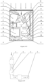
Figure 1 is a schematic diagram of an acoustic absorber composed of a micro-perforated plate and six acoustic filters. -
Figure 2 is a schematic diagram of an acoustic absorber composed of a micro-perforated plate and six acoustic filters. -
Figure 3 is a schematic diagram of an acoustic absorber composed of a micro-perforated plate and five acoustic filters. -
Figure 4 is a L-shaped main acoustic propagation passage. -
Figure 5 is a U-shaped main acoustic propagation passage. -
Figure 6 is a spiral main acoustic propagation passage. -
Figure 7 is a S-shaped main acoustic propagation passage. -
Figure 8 is a multilayer main acoustic propagation passage. -
Figure 9 is an acoustic filter composed of a cavity and a variable cross-section section of the main acoustic propagation passage. -
Figure 10 is an acoustic filter composed of a cavity, a thin branch pipe and a section of the main acoustic propagation passage. -
Figure 11 is an acoustic filter composed of a cavity and a variable cross-section section of the main acoustic propagation passage, where the main acoustic propagation passage extends inside the cavity. -
Figure 12 is an acoustic filter composed of a cavity, a thin branch pipe and a variable cross-section section of the main acoustic propagation passage with, where the thin branch pipe extends inside the main acoustic propagation passage. -
Figure 13 is an acoustic filter composed of a cavity and a section of the main acoustic propagation passage. -
Figure 14 is an acoustic filter composed of a cavity and a section of the main acoustic propagation passage. -
Figure 15 is an acoustic filter composed of two cavities, a thin branch pipe and a variable cross-section section of the main acoustic propagation passage, where the thin branch pipe connects the two cavities. -
Figure 16 is an acoustic filter composed of two cavities, a thin branch pipe and a section of the main acoustic propagation passage, where the thin branch pipe connects the two cavities and extends inside the cavities. -
Figure 17 is an acoustic filter composed of two cavities, multiple thin branch pipes and a variable cross-section section of the main acoustic propagation passage, where the thin branch pipes connect the two cavities and extend inside the cavities. -
Figure 18 is an acoustic filter composed of two cavities, a thin branch pipe and a variable cross-section section of the main acoustic propagation passage. -
Figure 19 is an acoustic filter composed of two cavities, a thin branch pipe and a section of the main acoustic propagation passage. -
Figure 20 is an acoustic filter composed of two cavities, two thin branch pipes and a section of the main acoustic propagation passage, where the two thin branch pipes connect the two cavities. -
Figure 21 is an acoustic filter composed of two cavities, two thin branch pipes and a variable cross-section section of the main acoustic propagation passage, where one thin branch pipe connects the two cavities and the other connects a cavity to the main acoustic propagation passage and extends inside the cavity and the main acoustic propagation passage. -
Figure 22 is an acoustic filter composed of two cavities, a thin branch pipe and a variable cross-section section of the main acoustic propagation passage. -
Figure 23 is an acoustic filter composed of two cavities, a thin branch pipe and a variable cross-section section of the main acoustic propagation passage, where the thin branch pipe extends inside the cavities. -
Figure 24 is an acoustic filter composed of three cavities, two thin branch pipes and a variable cross-section section of the main acoustic propagation passage, where one thin branch pipe extends inside the cavities and the other doesn't, and the main acoustic propagation passage extends inside the cavity. -
Figure 25 is an acoustic filter composed of three cavities, multiple thin branch pipes and a section of the main acoustic propagation passage, where some thin branch pipes extend inside the cavities and the others don't. -
Figure 26 is an acoustic filter composed of three cavities, multiple thin branch pipes and a variable cross-section section of the main acoustic propagation passage. -
Figure 27 is an acoustic filter composed of five cavities, multiple thin branch pipes and a variable cross-section section of the main acoustic propagation passage, where some thin branch pipes extend inside the cavities and the others don't. - In the figures:
- 1.the micro-perforated plate; 2.the cavity behind the micro-perforated plate; 3.the open end of the main acoustic propagation passage (the outlet of the cavity behind the micro-perforated plate); 4.the main acoustic propagation passage; 5.the closed end of the main acoustic propagation passage; 6.the acoustic filter arranged along the main acoustic propagation passage; 7.the thin branch pipe; 8.the interface cavity of the acoustic filter; 9.the auxiliary cavity of the acoustic filter;
- 1 1.the first acoustic filter arranged along the main acoustic propagation passage; 12.the second acoustic filter arranged along the main acoustic propagation passage; 13. the third acoustic filter arranged along the main acoustic propagation passage; 14.the fourth acoustic filter arranged along the main acoustic propagation passage; 15.the fifth acoustic filter arranged along the main acoustic propagation passage; 16.the sixth acoustic filter arranged along the main acoustic propagation passage; 17.the first layer of the main acoustic propagation passage; 18.the second layer of the main acoustic propagation passage; 19.the third layer of the main acoustic propagation passage; 20.the communicating hole between adjacent layers of the multilayer main acoustic propagation passage;
- The arrows in the figures indicate the propagation direction of acoustic waves.
- The acoustic absorber comprises a
micro-perforated plate 1, acavity 2 behind themicro-perforated plate 1, a mainacoustic propagation passage 4 communicating with thecavity 2, and six acoustic filters arranged along the mainacoustic propagation passage 4; - For the
micro-perforated plate 1, one side is the incident surface of external acoustic waves, and the other side is thecavity 2 formed by the side wall; - The
cavity 2 has two open ends; one end is open to themicro-perforated plate 1 and is defined as the inlet of the cavity; and the other end is open to the mainacoustic propagation passage 4, and is defined as the outlet of the cavity; compared with the inlet of the cavity, the outlet of the cavity is narrower; the volume of thecavity 2 is estimated as the product of the area of themicro-perforated plate 1 and the perforation rate of themicro-perforated plate 1; acoustic waves in thecavity 2 propagate along the direction from the inlet to the outlet, and finally enter the mainacoustic propagation passage 4; - The main
acoustic propagation passage 4 is a single-layer U-shaped passage communicating with thecavity 2; oneend 3 of the mainacoustic propagation passage 4 is the outlet of thecavity 2, and theother end 5 of the mainacoustic propagation passage 4 is closed; the two ends of the mainacoustic propagation passage 4 are connected so that acoustic waves in the mainacoustic propagation passage 4 can propagate from theopen end 3 to theclosed end 5; the mainacoustic propagation passage 4 has variable cross-section; acoustic absorbing materials are arranged inside the mainacoustic propagation passage 4; - Along the main
acoustic propagation passage 4, six acoustic filters (11, 12, 13, 14, 15 and 16) are arranged from theopen end 3 to theclosed end 5; these six acoustic filters have different cut-off frequencies and are arranged in the order of cut-off frequency from high to low; it is assumed that, the cut-off frequencies ofacoustic filters acoustic filters acoustic filter 11 is the first acoustic filter arranged near theopen end 3, having the highest cut-off frequency f1 and the lowest volume V1; theacoustic filter 16 is the last acoustic filter arranged near theclosed end 5, having the lowest cut-off frequency f6 and the biggest volume V6; - For the six
acoustic filters acoustic filter 11 is composed of a cavity and a variable cross-section section of the mainacoustic propagation passage 4, and the cavity communicates directly with the mainacoustic propagation passage 4; theacoustic filter 12 is composed of a cavity and a uniform cross-section section of the mainacoustic propagation passage 4, and the cavity communicates directly with the mainacoustic propagation passage 4; theacoustic filter 13 is composed of a cavity and a uniform cross-section section of the mainacoustic propagation passage 4, and the cavity communicates directly with the mainacoustic propagation passage 4; theacoustic filter 14 is composed of a cavity and a variable cross-section section of the mainacoustic propagation passage 4, and the cavity communicates directly with the mainacoustic propagation passage 4; theacoustic filter 15 is composed of a cavity and a variable cross-section section of the mainacoustic propagation passage 4, and the cavity communicates directly with the mainacoustic propagation passage 4; theacoustic filter 16 is composed of a cavity and a variable cross-section section of the mainacoustic propagation passage 4, and the cavity communicates directly with the mainacoustic propagation passage 4; - After passing through the
micro-perforated plate 1 and thecavity 2, acoustic waves enter the mainacoustic propagation passage 4 and are guided to propagate from theopen end 3 to theclosed end 5; at each acoustic filter (11, 12, 13, 14, 15 or 16), acoustic waves are divided into two parts, where one part goes into the acoustic filter and is absorbed or reflected, and the other part continues propagating along the mainacoustic propagation passage 4. - The embodiment and
embodiment 1 are identical but only differ in that: - ① the
acoustic filter 13 is composed of a cavity and a variable cross-section section of the mainacoustic propagation passage 4; - ② the
acoustic filter 14 is composed of a cavity and a variable cross-section section of the mainacoustic propagation passage 4, and the section of the mainacoustic propagation passage 4 extends inside the cavity; - ③ the
acoustic filter 15 is composed of aninterface cavity 8, anauxiliary cavity 9, athin branch pipe 7 connecting thecavities acoustic propagation passage 4, and thethin branch pipe 7 extends inside thecavities - ④ the
acoustic filter 16 is composed of aninterface cavity 8, anauxiliary cavity 9, athin branch pipe 7 connecting thecavities acoustic propagation passage 4, and thethin branch pipe 7 doesn't extend inside thecavities - ⑤ acoustic absorbing materials are arranged inside the
cavities - The acoustic absorber comprises a
micro-perforated plate 1, acavity 2 behind themicro-perforated plate 1, a mainacoustic propagation passage 4 communicating with thecavity 2, and five acoustic filters arranged along the mainacoustic propagation passage 4; - For the
micro-perforated plate 1, one side is the incident surface of external acoustic waves, and the other side is thecavity 2 formed by the side wall; - The
cavity 2 has two open ends; one end is open to themicro-perforated plate 1 and is defined as the inlet of the cavity; and the other end is open to the mainacoustic propagation passage 4, and is defined as the outlet of the cavity; compared with the inlet of the cavity, the outlet of the cavity is narrower; the volume of thecavity 2 is estimated as the product of the area of themicro-perforated plate 1 and the perforation rate of themicro-perforated plate 1; acoustic waves in thecavity 2 propagate along the direction from the inlet to the outlet, and finally enter the mainacoustic propagation passage 4; - The main
acoustic propagation passage 4 is a single-layer curved passage communicating with thecavity 2; oneend 3 of the mainacoustic propagation passage 4 is the outlet of thecavity 2, and theother end 5 of the mainacoustic propagation passage 4 is closed; the two ends of the mainacoustic propagation passage 4 are connected so that acoustic waves in the mainacoustic propagation passage 4 can propagate from theopen end 3 to theclosed end 5; acoustic absorbing materials are arranged near the acoustic filters inside the mainacoustic propagation passage 4; - Along the main
acoustic propagation passage 4, five acoustic filters (11, 12, 13, 14 and 15) are arranged from theopen end 3 to theclosed end 5; these five acoustic filters have different cut-off frequencies and are arranged in the order of cut-off frequency from high to low; it is assumed that, the cut-off frequencies ofacoustic filters acoustic filters acoustic filter 11 is the first acoustic filter arranged near theopen end 3, having the highest cut-off frequency f1 and the lowest volume V1; theacoustic filter 15 is the last acoustic filter arranged near theclosed end 5, having the lowest cut-off frequency f5 and the biggest volume V5; - For the five acoustic filters 11, 12, 13, 14 and 15, the acoustic filter 11 is composed of a cavity and a section of the main acoustic propagation passage 4, and the cavity communicates directly with the main acoustic propagation passage 4; the acoustic filter 12 is composed of a cavity and a section of the main acoustic propagation passage 4, and the cavity communicates directly with the main acoustic propagation passage 4; the acoustic filter 13 is composed of an interface cavity 8, an auxiliary cavity 9, a thin branch pipe 7 connecting the cavities 8 and 9, and a section of the main acoustic propagation passage 4, and the interface cavity 8 communicates directly with the main acoustic propagation passage 4; the acoustic filter 14 is composed of an interface cavity 8, an auxiliary cavity 9, a thin branch pipe 7 connecting the cavities 8 and 9, and a section of the main acoustic propagation passage 4, and the interface cavity 8 communicates directly with the main acoustic propagation passage 4; the acoustic filter 15 is composed of an interface cavity 8, two auxiliary cavities 9, three thin branch pipes 7 connecting the cavities 8 and 9 as well as the main acoustic propagation passage 4, and a section of the main acoustic propagation passage 4, where the interface cavity 8 communicates with the main acoustic propagation passage 4 through a thin branch pipe 7 and the thin branch pipe 7 connecting two auxiliary cavities 9 extends inside the cavities;
- After passing through the
micro-perforated plate 1 and thecavity 2, acoustic waves enter the mainacoustic propagation passage 4 and are guided to propagate from theopen end 3 to theclosed end 5; at each acoustic filter (11, 12, 13, 14 or 15), acoustic waves are divided into two parts, where one part goes into the acoustic filter and is absorbed or reflected, and the other part continues propagating along the mainacoustic propagation passage 4. - The embodiment and
embodiment 1 are identical but only differ in that:
the mainacoustic propagation passage 4 is a single-layer curved passage inFigure 4 orFigure 5 orFigure 6 orFigure 7 . - The embodiment and
embodiment 3 are identical but only differ in that: - ① the main
acoustic propagation passage 4 is a multi-layer passage inFigure 8 , and at least one communicatinghole 20 is manufactured between adjacent layers of the multilayer main acoustic propagation passage to ensure that acoustic waves can propagate from theopen end 3 to theclosed end 5; - ② the
acoustic filters Figure 9 or Figure 10 or Figure 11 or Figure 12 or Figure 13 or Figure 14 ; - ③ the
acoustic filters Figure 15 or Figure 16 orFigure 17 or Figure 18 orFigure 19 orFigure 20 orFigure 21 or Figure 22 orFigure 23 ; - ④ the
acoustic filter 15 is as shown inFigure 24 or Figure 25 orFigure 26 . - The embodiment and
embodiment 3 are identical but only differ in that, theacoustic filter 15 is composed of twointerface cavity 8, threeauxiliary cavities 9, multiplethin branch pipes 7 connecting thecavities acoustic propagation passage 4, and a section of the mainacoustic propagation passage 4, as shown inFigure 27 .
Claims (3)
- A type of acoustic absorber composed of a micro-perforated plate and a set of acoustic filters, characterized by:comprising a micro-perforated plate, a cavity behind the micro-perforated plate, a main acoustic propagation passage communicating with the cavity behind the micro-perforated plate, and a set of acoustic filters arranged along the main acoustic propagation passage;wherein the micro-perforated plate has a plate thickness less than or equal to 2mm and a perforation rate less than or equal to 5%, and diameters of the perforations on the micro-perforated plate are not bigger than 0.5mm; one side of the micro-perforated plate is the incident surface of external acoustic waves, and the other side is a cavity formed by the side wall; after external acoustic waves pass through the micro-perforated plate, they will enter the cavity behind the micro-perforated plate and travel in the cavity;wherein the cavity behind the micro-perforated plate connects the micro-perforated plate with the main acoustic propagation passage; the cavity only has two open ends; one end of the cavity is open to the micro-perforated plate and is defined as the inlet; the other end of the cavity is open to the main acoustic propagation passage, and is defined as the outlet; compared with the inlet of the cavity, the outlet of the cavity is narrower; the volume of the cavity is estimated as the product of the area of the micro-perforated plate and the perforation rate of the micro-perforated plate; acoustic waves in the cavity propagate along the direction from the inlet to the outlet, and finally enter the main acoustic propagation passage;wherein the main acoustic propagation passage is a slender and curved passage communicating with the cavity behind the micro-perforated plate; one end of the main acoustic propagation passage is open to the cavity behind the micro-perforated plate, and the other end is closed; acoustic waves in the main acoustic propagation passage can propagate from the open end to the closed end; the main acoustic propagation passage has the variable cross-section; the main acoustic propagation passage is closely arranged through the measures of circuity, bending, coiling or stacking in a monolayer or multilayer structural form; according to design requirements, acoustic absorbing materials can be arranged inside the main acoustic propagation passage;wherein a set of acoustic filters are arranged along the main acoustic propagation passage from the open end to the closed end of the main acoustic propagation passage; these acoustic filters have different cut-off frequencies and are arranged in the order of cut-off frequency from high to low; if the ith acoustic filter in these acoustic filters is Ni and its cut-off frequency is fi, where i=1, 2 ······ n, these acoustic filters arranged from the open end to the closed end of the main acoustic propagation passage are N1, N2 ··· ··· Ni ··· ··· Nn and their cut-off frequencies satisfy f1> f2>······>fi>······>fn; N1 is the first acoustic filter arranged near the open end of the main acoustic propagation passage and has the highest cut-off frequency f1; Nn is the last one arranged near the closed end of the main acoustic propagation passage and has the lowest cut-off frequency fn;after passing through the micro-perforated plate and the cavity behind the micro-perforated plate, acoustic waves enter the main acoustic propagation passage and are guided to propagate from the open end to the closed end of the main acoustic propagation passage; at each acoustic filter arranged along the main acoustic propagation passage, acoustic waves are divided into two parts, where one part goes into the acoustic filter and is absorbed or reflected, and the other part continues propagating along the main acoustic propagation passage;wherein each acoustic filter is constructed by a section of the main acoustic propagation passage and at least one cavity, where the section of the main acoustic propagation passage communicates with the cavity; while an acoustic filter only comprises a cavity, the cavity communicates with the section of the main acoustic propagation passage directly or indirectly, such as communicating through a thin branch pipe; while an acoustic filter comprises multiple cavities, the cavity adjacent to the section of the main acoustic propagation passage is defined as the interface cavity, which communicates with the section of the main acoustic propagation passage directly or indirectly, such as communicating through a thin branch pipe; while an acoustic filter comprises multiple cavities, all cavities are connected directly or indirectly to ensure that acoustic waves can enter all the cavities and propagate in these cavities; according to design requirements, one or multiple thin branch pipes can be arranged between a cavity of the acoustic filter and the main acoustic propagation passage; during acoustic waves propagate in an acoustic filter, one part of the acoustic energy is absorbed and the other part is reflected;wherein each cavity of an acoustic filter is formed by multiple free surfaces, or by multiple planes, or by multiple surfaces and planes; according to design requirements, acoustic absorbing materials can be arranged inside the cavity;the volume of each acoustic filter is the sum of equivalent volumes of all cavities of the acoustic filter; if using Vi (i=1, 2 ······ n) to stand for the volume of the ith acoustic filter Ni (i=1, 2 ······ n), these acoustic filters N1, N2······Ni······Nn, arranged in the order of cut-off frequency from high to low from the open end to the closed end of the main acoustic propagation passage, satisfy V1< V2<······< Vi<······ <Vn; N1 is the first acoustic filter arranged near the open end of the main acoustic propagation passage, having the highest cut-off frequency f1 and the lowest volume V1; Nn is the last one arranged near the closed end of the main acoustic propagation passage, having the lowest cut-off frequency fn and the biggest volume Vn;this type of acoustic absorber is characterized by adopting a main acoustic propagation passage to provide different phase delay for a micro-perforated plate to realize that a micro-perforated plate effectively absorbs broadband acoustic waves, and by combing the close arrangement of main acoustic propagation passage to achieve an ultra-thin structure.
- This type of acoustic absorber composed of a micro-perforated plate and a set of acoustic filters of claim 1, characterized in that: in each acoustic filter arranged along the main acoustic propagation passage, it must be ensured that each cavity of the acoustic filter communicates directly or indirectly with the main acoustic propagation passage to provide at least a propagation path for acoustic waves between each cavity of the acoustic filter and the main acoustic propagation passage.
- This type of acoustic absorber composed of a micro-perforated plate and a set of acoustic filters of claim 1, characterized in that: the thin branch pipe connecting a cavity of an acoustic filter and the main acoustic propagation passage can extend inside the cavity or doesn't extend; the thin branch pipe connecting a cavity of an acoustic filter and the main acoustic propagation passage can extend inside the main acoustic propagation passage or doesn't extend; the thin branch pipe connecting different cavities of an acoustic filter can extend inside the cavity or doesn't extend; while the cavity of the acoustic filter communicates with the main acoustic propagation passage directly, the main acoustic propagation passage can extend inside the cavity or doesn't extend.
Applications Claiming Priority (1)
| Application Number | Priority Date | Filing Date | Title |
|---|---|---|---|
| PCT/CN2021/115552 WO2023028813A1 (en) | 2021-08-31 | 2021-08-31 | Low-pass acoustic filter bank broadband sound absorber |
Publications (3)
| Publication Number | Publication Date |
|---|---|
| EP4174843A4 EP4174843A4 (en) | 2023-05-03 |
| EP4174843A1 true EP4174843A1 (en) | 2023-05-03 |
| EP4174843B1 EP4174843B1 (en) | 2024-07-31 |
Family
ID=85411764
Family Applications (1)
| Application Number | Title | Priority Date | Filing Date |
|---|---|---|---|
| EP21912326.2A Active EP4174843B1 (en) | 2021-08-31 | 2021-08-31 | Low-pass acoustic filter bank broadband sound absorber |
Country Status (3)
| Country | Link |
|---|---|
| US (1) | US20230215411A1 (en) |
| EP (1) | EP4174843B1 (en) |
| WO (1) | WO2023028813A1 (en) |
Families Citing this family (1)
| Publication number | Priority date | Publication date | Assignee | Title |
|---|---|---|---|---|
| WO2026088172A1 (en) | 2024-10-25 | 2026-04-30 | Università Di Pisa | Sound absorption body and method for its production |
Family Cites Families (8)
| Publication number | Priority date | Publication date | Assignee | Title |
|---|---|---|---|---|
| KR101026765B1 (en) * | 2009-05-19 | 2011-04-11 | 한국항공우주연구원 | Clean sound absorber for broadband noise control and manufacturing method thereof |
| CN101727894B (en) * | 2010-01-08 | 2012-05-23 | 中国科学院声学研究所 | Composite sound absorbing device with built-in resonant cavity |
| WO2018195836A1 (en) * | 2017-04-26 | 2018-11-01 | 大连理工大学 | Broadband ultra-thin sound absorbing and insulating structure controlling sound wave propagation path |
| CN107071663B (en) * | 2017-04-26 | 2022-09-06 | 大连理工大学 | Broadband ultra-thin sound wave diffusion structure |
| CN109147750A (en) * | 2018-11-15 | 2019-01-04 | 中车株洲电力机车有限公司 | A kind of low frequency coupling sound absorption structure |
| CN111402852B (en) * | 2019-01-02 | 2023-02-28 | 香港科技大学 | Low frequency sound absorption and soft boundary effect of frequency discrete active panels |
| CN110503936B (en) * | 2019-08-13 | 2021-10-12 | 安徽建筑大学 | Adjustable sub-wavelength low frequency sound absorption structure |
| CN112049269B (en) * | 2020-08-19 | 2023-01-24 | 中国铁路设计集团有限公司 | Combined frequency band type sound absorption composite structure |
-
2021
- 2021-08-31 EP EP21912326.2A patent/EP4174843B1/en active Active
- 2021-08-31 US US17/792,026 patent/US20230215411A1/en not_active Abandoned
- 2021-08-31 WO PCT/CN2021/115552 patent/WO2023028813A1/en not_active Ceased
Also Published As
| Publication number | Publication date |
|---|---|
| EP4174843B1 (en) | 2024-07-31 |
| WO2023028813A1 (en) | 2023-03-09 |
| US20230215411A1 (en) | 2023-07-06 |
| EP4174843A4 (en) | 2023-05-03 |
Similar Documents
| Publication | Publication Date | Title |
|---|---|---|
| CN108909083B (en) | A sound-absorbing and insulating sandwich panel with a labyrinth back cavity | |
| Shen et al. | Broadband low-frequency acoustic metamuffler | |
| CN113571034B (en) | Broadband sound absorber of low-pass sound filter group | |
| Yang et al. | Acoustical performance of a wavy micro-perforated panel absorber | |
| CN109300464B (en) | Design method of low-frequency sound-absorbing body with gradual cross-section | |
| CN116733787B (en) | A three-dimensional composite metamorphic muffler module and muffler | |
| CN116153280B (en) | A composite broadband noise reduction superstructure | |
| CN105845122A (en) | Ultrathin bi-directional sound obstruction channel | |
| CN115083376A (en) | Low-frequency broadband thin layer sound absorption device and noise reduction method | |
| EP4174843B1 (en) | Low-pass acoustic filter bank broadband sound absorber | |
| Sun et al. | An ultrathin high-order micro-perforated meta-liner for broadband sound attenuation under grazing flow | |
| CN209993345U (en) | Hybrid silencer and silencing system | |
| CN209111647U (en) | A sound absorption and sound insulation sandwich panel with labyrinth back cavity | |
| CN203441570U (en) | Impedance composite muffler | |
| CN108487487A (en) | A kind of compound wedge absorber | |
| CN218883352U (en) | Pipeline type broadband sound insulation structure | |
| CN217506885U (en) | muffler structure | |
| CN118824219A (en) | Noise reduction method, multi-layer curled composite sound-absorbing structure and sound-absorbing noise reduction method | |
| CN105864155A (en) | Pressure pulsation suppression method for full-band hydraulic system | |
| CN219591109U (en) | Ultralow-frequency large-bandwidth mute material | |
| CN116123381B (en) | Broadband noise elimination structure based on curling cavity | |
| CN115065908B (en) | Loudspeaker module | |
| CN117831491A (en) | A multilayer embedded Helmholtz resonator and its design method | |
| CN205908337U (en) | Compound silencer and have its vehicle | |
| CN116045117A (en) | Pipeline class broadband sound insulation structure |
Legal Events
| Date | Code | Title | Description |
|---|---|---|---|
| STAA | Information on the status of an ep patent application or granted ep patent |
Free format text: STATUS: UNKNOWN |
|
| STAA | Information on the status of an ep patent application or granted ep patent |
Free format text: STATUS: THE INTERNATIONAL PUBLICATION HAS BEEN MADE |
|
| PUAI | Public reference made under article 153(3) epc to a published international application that has entered the european phase |
Free format text: ORIGINAL CODE: 0009012 |
|
| STAA | Information on the status of an ep patent application or granted ep patent |
Free format text: STATUS: REQUEST FOR EXAMINATION WAS MADE |
|
| 17P | Request for examination filed |
Effective date: 20220706 |
|
| A4 | Supplementary search report drawn up and despatched |
Effective date: 20230306 |
|
| AK | Designated contracting states |
Kind code of ref document: A1 Designated state(s): AL AT BE BG CH CY CZ DE DK EE ES FI FR GB GR HR HU IE IS IT LI LT LU LV MC MK MT NL NO PL PT RO RS SE SI SK SM TR |
|
| GRAP | Despatch of communication of intention to grant a patent |
Free format text: ORIGINAL CODE: EPIDOSNIGR1 |
|
| STAA | Information on the status of an ep patent application or granted ep patent |
Free format text: STATUS: GRANT OF PATENT IS INTENDED |
|
| RIC1 | Information provided on ipc code assigned before grant |
Ipc: E04B 1/86 20060101ALI20230601BHEP Ipc: E04B 1/84 20060101ALI20230601BHEP Ipc: G10K 11/04 20060101ALI20230601BHEP Ipc: G10K 11/172 20060101ALI20230601BHEP Ipc: G10K 11/162 20060101ALI20230601BHEP Ipc: G10K 11/16 20060101AFI20230601BHEP |
|
| INTG | Intention to grant announced |
Effective date: 20230622 |
|
| GRAJ | Information related to disapproval of communication of intention to grant by the applicant or resumption of examination proceedings by the epo deleted |
Free format text: ORIGINAL CODE: EPIDOSDIGR1 |
|
| STAA | Information on the status of an ep patent application or granted ep patent |
Free format text: STATUS: REQUEST FOR EXAMINATION WAS MADE |
|
| INTC | Intention to grant announced (deleted) | ||
| GRAP | Despatch of communication of intention to grant a patent |
Free format text: ORIGINAL CODE: EPIDOSNIGR1 |
|
| STAA | Information on the status of an ep patent application or granted ep patent |
Free format text: STATUS: GRANT OF PATENT IS INTENDED |
|
| INTG | Intention to grant announced |
Effective date: 20230908 |
|
| GRAS | Grant fee paid |
Free format text: ORIGINAL CODE: EPIDOSNIGR3 |
|
| GRAA | (expected) grant |
Free format text: ORIGINAL CODE: 0009210 |
|
| STAA | Information on the status of an ep patent application or granted ep patent |
Free format text: STATUS: THE PATENT HAS BEEN GRANTED |
|
| DAV | Request for validation of the european patent (deleted) | ||
| DAX | Request for extension of the european patent (deleted) | ||
| AK | Designated contracting states |
Kind code of ref document: B1 Designated state(s): AL AT BE BG CH CY CZ DE DK EE ES FI FR GB GR HR HU IE IS IT LI LT LU LV MC MK MT NL NO PL PT RO RS SE SI SK SM TR |
|
| REG | Reference to a national code |
Ref country code: CH Ref legal event code: EP Ref country code: GB Ref legal event code: FG4D |
|
| REG | Reference to a national code |
Ref country code: DE Ref legal event code: R096 Ref document number: 602021016624 Country of ref document: DE |
|
| REG | Reference to a national code |
Ref country code: IE Ref legal event code: FG4D |
|
| PGFP | Annual fee paid to national office [announced via postgrant information from national office to epo] |
Ref country code: DE Payment date: 20240830 Year of fee payment: 4 |
|
| REG | Reference to a national code |
Ref country code: LT Ref legal event code: MG9D |
|
| REG | Reference to a national code |
Ref country code: NL Ref legal event code: MP Effective date: 20240731 |
|
| PG25 | Lapsed in a contracting state [announced via postgrant information from national office to epo] |
Ref country code: PT Free format text: LAPSE BECAUSE OF FAILURE TO SUBMIT A TRANSLATION OF THE DESCRIPTION OR TO PAY THE FEE WITHIN THE PRESCRIBED TIME-LIMIT Effective date: 20241202 |
|
| REG | Reference to a national code |
Ref country code: AT Ref legal event code: MK05 Ref document number: 1709239 Country of ref document: AT Kind code of ref document: T Effective date: 20240731 |
|
| PG25 | Lapsed in a contracting state [announced via postgrant information from national office to epo] |
Ref country code: PT Free format text: LAPSE BECAUSE OF FAILURE TO SUBMIT A TRANSLATION OF THE DESCRIPTION OR TO PAY THE FEE WITHIN THE PRESCRIBED TIME-LIMIT Effective date: 20241202 |
|
| PG25 | Lapsed in a contracting state [announced via postgrant information from national office to epo] |
Ref country code: NO Free format text: LAPSE BECAUSE OF FAILURE TO SUBMIT A TRANSLATION OF THE DESCRIPTION OR TO PAY THE FEE WITHIN THE PRESCRIBED TIME-LIMIT Effective date: 20241031 |
|
| PG25 | Lapsed in a contracting state [announced via postgrant information from national office to epo] |
Ref country code: NL Free format text: LAPSE BECAUSE OF FAILURE TO SUBMIT A TRANSLATION OF THE DESCRIPTION OR TO PAY THE FEE WITHIN THE PRESCRIBED TIME-LIMIT Effective date: 20240731 Ref country code: FI Free format text: LAPSE BECAUSE OF FAILURE TO SUBMIT A TRANSLATION OF THE DESCRIPTION OR TO PAY THE FEE WITHIN THE PRESCRIBED TIME-LIMIT Effective date: 20240731 Ref country code: PL Free format text: LAPSE BECAUSE OF FAILURE TO SUBMIT A TRANSLATION OF THE DESCRIPTION OR TO PAY THE FEE WITHIN THE PRESCRIBED TIME-LIMIT Effective date: 20240731 Ref country code: GR Free format text: LAPSE BECAUSE OF FAILURE TO SUBMIT A TRANSLATION OF THE DESCRIPTION OR TO PAY THE FEE WITHIN THE PRESCRIBED TIME-LIMIT Effective date: 20241101 |
|
| PG25 | Lapsed in a contracting state [announced via postgrant information from national office to epo] |
Ref country code: BG Free format text: LAPSE BECAUSE OF FAILURE TO SUBMIT A TRANSLATION OF THE DESCRIPTION OR TO PAY THE FEE WITHIN THE PRESCRIBED TIME-LIMIT Effective date: 20240731 |
|
| PG25 | Lapsed in a contracting state [announced via postgrant information from national office to epo] |
Ref country code: LV Free format text: LAPSE BECAUSE OF FAILURE TO SUBMIT A TRANSLATION OF THE DESCRIPTION OR TO PAY THE FEE WITHIN THE PRESCRIBED TIME-LIMIT Effective date: 20240731 |
|
| PG25 | Lapsed in a contracting state [announced via postgrant information from national office to epo] |
Ref country code: IS Free format text: LAPSE BECAUSE OF FAILURE TO SUBMIT A TRANSLATION OF THE DESCRIPTION OR TO PAY THE FEE WITHIN THE PRESCRIBED TIME-LIMIT Effective date: 20241130 Ref country code: AT Free format text: LAPSE BECAUSE OF FAILURE TO SUBMIT A TRANSLATION OF THE DESCRIPTION OR TO PAY THE FEE WITHIN THE PRESCRIBED TIME-LIMIT Effective date: 20240731 |
|
| PG25 | Lapsed in a contracting state [announced via postgrant information from national office to epo] |
Ref country code: HR Free format text: LAPSE BECAUSE OF FAILURE TO SUBMIT A TRANSLATION OF THE DESCRIPTION OR TO PAY THE FEE WITHIN THE PRESCRIBED TIME-LIMIT Effective date: 20240731 |
|
| PG25 | Lapsed in a contracting state [announced via postgrant information from national office to epo] |
Ref country code: ES Free format text: LAPSE BECAUSE OF FAILURE TO SUBMIT A TRANSLATION OF THE DESCRIPTION OR TO PAY THE FEE WITHIN THE PRESCRIBED TIME-LIMIT Effective date: 20240731 Ref country code: RS Free format text: LAPSE BECAUSE OF FAILURE TO SUBMIT A TRANSLATION OF THE DESCRIPTION OR TO PAY THE FEE WITHIN THE PRESCRIBED TIME-LIMIT Effective date: 20241031 |
|
| PG25 | Lapsed in a contracting state [announced via postgrant information from national office to epo] |
Ref country code: RS Free format text: LAPSE BECAUSE OF FAILURE TO SUBMIT A TRANSLATION OF THE DESCRIPTION OR TO PAY THE FEE WITHIN THE PRESCRIBED TIME-LIMIT Effective date: 20241031 Ref country code: PL Free format text: LAPSE BECAUSE OF FAILURE TO SUBMIT A TRANSLATION OF THE DESCRIPTION OR TO PAY THE FEE WITHIN THE PRESCRIBED TIME-LIMIT Effective date: 20240731 Ref country code: NO Free format text: LAPSE BECAUSE OF FAILURE TO SUBMIT A TRANSLATION OF THE DESCRIPTION OR TO PAY THE FEE WITHIN THE PRESCRIBED TIME-LIMIT Effective date: 20241031 Ref country code: NL Free format text: LAPSE BECAUSE OF FAILURE TO SUBMIT A TRANSLATION OF THE DESCRIPTION OR TO PAY THE FEE WITHIN THE PRESCRIBED TIME-LIMIT Effective date: 20240731 Ref country code: LV Free format text: LAPSE BECAUSE OF FAILURE TO SUBMIT A TRANSLATION OF THE DESCRIPTION OR TO PAY THE FEE WITHIN THE PRESCRIBED TIME-LIMIT Effective date: 20240731 Ref country code: IS Free format text: LAPSE BECAUSE OF FAILURE TO SUBMIT A TRANSLATION OF THE DESCRIPTION OR TO PAY THE FEE WITHIN THE PRESCRIBED TIME-LIMIT Effective date: 20241130 Ref country code: HR Free format text: LAPSE BECAUSE OF FAILURE TO SUBMIT A TRANSLATION OF THE DESCRIPTION OR TO PAY THE FEE WITHIN THE PRESCRIBED TIME-LIMIT Effective date: 20240731 Ref country code: GR Free format text: LAPSE BECAUSE OF FAILURE TO SUBMIT A TRANSLATION OF THE DESCRIPTION OR TO PAY THE FEE WITHIN THE PRESCRIBED TIME-LIMIT Effective date: 20241101 Ref country code: FI Free format text: LAPSE BECAUSE OF FAILURE TO SUBMIT A TRANSLATION OF THE DESCRIPTION OR TO PAY THE FEE WITHIN THE PRESCRIBED TIME-LIMIT Effective date: 20240731 Ref country code: ES Free format text: LAPSE BECAUSE OF FAILURE TO SUBMIT A TRANSLATION OF THE DESCRIPTION OR TO PAY THE FEE WITHIN THE PRESCRIBED TIME-LIMIT Effective date: 20240731 Ref country code: BG Free format text: LAPSE BECAUSE OF FAILURE TO SUBMIT A TRANSLATION OF THE DESCRIPTION OR TO PAY THE FEE WITHIN THE PRESCRIBED TIME-LIMIT Effective date: 20240731 Ref country code: AT Free format text: LAPSE BECAUSE OF FAILURE TO SUBMIT A TRANSLATION OF THE DESCRIPTION OR TO PAY THE FEE WITHIN THE PRESCRIBED TIME-LIMIT Effective date: 20240731 |
|
| REG | Reference to a national code |
Ref country code: CH Ref legal event code: PL |
|
| PG25 | Lapsed in a contracting state [announced via postgrant information from national office to epo] |
Ref country code: SM Free format text: LAPSE BECAUSE OF FAILURE TO SUBMIT A TRANSLATION OF THE DESCRIPTION OR TO PAY THE FEE WITHIN THE PRESCRIBED TIME-LIMIT Effective date: 20240731 Ref country code: RO Free format text: LAPSE BECAUSE OF FAILURE TO SUBMIT A TRANSLATION OF THE DESCRIPTION OR TO PAY THE FEE WITHIN THE PRESCRIBED TIME-LIMIT Effective date: 20240731 Ref country code: DK Free format text: LAPSE BECAUSE OF FAILURE TO SUBMIT A TRANSLATION OF THE DESCRIPTION OR TO PAY THE FEE WITHIN THE PRESCRIBED TIME-LIMIT Effective date: 20240731 |
|
| PG25 | Lapsed in a contracting state [announced via postgrant information from national office to epo] |
Ref country code: LU Free format text: LAPSE BECAUSE OF NON-PAYMENT OF DUE FEES Effective date: 20240831 |
|
| PG25 | Lapsed in a contracting state [announced via postgrant information from national office to epo] |
Ref country code: MC Free format text: LAPSE BECAUSE OF FAILURE TO SUBMIT A TRANSLATION OF THE DESCRIPTION OR TO PAY THE FEE WITHIN THE PRESCRIBED TIME-LIMIT Effective date: 20240731 Ref country code: CH Free format text: LAPSE BECAUSE OF NON-PAYMENT OF DUE FEES Effective date: 20240831 Ref country code: EE Free format text: LAPSE BECAUSE OF FAILURE TO SUBMIT A TRANSLATION OF THE DESCRIPTION OR TO PAY THE FEE WITHIN THE PRESCRIBED TIME-LIMIT Effective date: 20240731 |
|
| PG25 | Lapsed in a contracting state [announced via postgrant information from national office to epo] |
Ref country code: CZ Free format text: LAPSE BECAUSE OF FAILURE TO SUBMIT A TRANSLATION OF THE DESCRIPTION OR TO PAY THE FEE WITHIN THE PRESCRIBED TIME-LIMIT Effective date: 20240731 |
|
| PG25 | Lapsed in a contracting state [announced via postgrant information from national office to epo] |
Ref country code: SK Free format text: LAPSE BECAUSE OF FAILURE TO SUBMIT A TRANSLATION OF THE DESCRIPTION OR TO PAY THE FEE WITHIN THE PRESCRIBED TIME-LIMIT Effective date: 20240731 Ref country code: IT Free format text: LAPSE BECAUSE OF FAILURE TO SUBMIT A TRANSLATION OF THE DESCRIPTION OR TO PAY THE FEE WITHIN THE PRESCRIBED TIME-LIMIT Effective date: 20240731 |
|
| REG | Reference to a national code |
Ref country code: DE Ref legal event code: R097 Ref document number: 602021016624 Country of ref document: DE |
|
| PLBE | No opposition filed within time limit |
Free format text: ORIGINAL CODE: 0009261 |
|
| STAA | Information on the status of an ep patent application or granted ep patent |
Free format text: STATUS: NO OPPOSITION FILED WITHIN TIME LIMIT |
|
| REG | Reference to a national code |
Ref country code: BE Ref legal event code: MM Effective date: 20240831 |
|
| 26N | No opposition filed |
Effective date: 20250501 |
|
| PG25 | Lapsed in a contracting state [announced via postgrant information from national office to epo] |
Ref country code: BE Free format text: LAPSE BECAUSE OF NON-PAYMENT OF DUE FEES Effective date: 20240831 |
|
| PG25 | Lapsed in a contracting state [announced via postgrant information from national office to epo] |
Ref country code: FR Free format text: LAPSE BECAUSE OF NON-PAYMENT OF DUE FEES Effective date: 20240930 |
|
| PG25 | Lapsed in a contracting state [announced via postgrant information from national office to epo] |
Ref country code: IE Free format text: LAPSE BECAUSE OF NON-PAYMENT OF DUE FEES Effective date: 20240831 |
|
| PG25 | Lapsed in a contracting state [announced via postgrant information from national office to epo] |
Ref country code: SE Free format text: LAPSE BECAUSE OF FAILURE TO SUBMIT A TRANSLATION OF THE DESCRIPTION OR TO PAY THE FEE WITHIN THE PRESCRIBED TIME-LIMIT Effective date: 20240731 |
|
| PG25 | Lapsed in a contracting state [announced via postgrant information from national office to epo] |
Ref country code: CY Free format text: LAPSE BECAUSE OF FAILURE TO SUBMIT A TRANSLATION OF THE DESCRIPTION OR TO PAY THE FEE WITHIN THE PRESCRIBED TIME-LIMIT; INVALID AB INITIO Effective date: 20210831 |
|
| REG | Reference to a national code |
Ref country code: DE Ref legal event code: R119 Ref document number: 602021016624 Country of ref document: DE |
|
| PG25 | Lapsed in a contracting state [announced via postgrant information from national office to epo] |
Ref country code: HU Free format text: LAPSE BECAUSE OF FAILURE TO SUBMIT A TRANSLATION OF THE DESCRIPTION OR TO PAY THE FEE WITHIN THE PRESCRIBED TIME-LIMIT; INVALID AB INITIO Effective date: 20210831 |
|
| GBPC | Gb: european patent ceased through non-payment of renewal fee |
Effective date: 20250831 |