EP4174830A1 - Display system - Google Patents
Display system Download PDFInfo
- Publication number
- EP4174830A1 EP4174830A1 EP22201446.6A EP22201446A EP4174830A1 EP 4174830 A1 EP4174830 A1 EP 4174830A1 EP 22201446 A EP22201446 A EP 22201446A EP 4174830 A1 EP4174830 A1 EP 4174830A1
- Authority
- EP
- European Patent Office
- Prior art keywords
- screen
- display
- unit
- black
- black screen
- Prior art date
- Legal status (The legal status is an assumption and is not a legal conclusion. Google has not performed a legal analysis and makes no representation as to the accuracy of the status listed.)
- Pending
Links
Images



Classifications
-
- H—ELECTRICITY
- H04—ELECTRIC COMMUNICATION TECHNIQUE
- H04N—PICTORIAL COMMUNICATION, e.g. TELEVISION
- H04N17/00—Diagnosis, testing or measuring for television systems or their details
- H04N17/04—Diagnosis, testing or measuring for television systems or their details for receivers
-
- G—PHYSICS
- G09—EDUCATION; CRYPTOGRAPHY; DISPLAY; ADVERTISING; SEALS
- G09G—ARRANGEMENTS OR CIRCUITS FOR CONTROL OF INDICATING DEVICES USING STATIC MEANS TO PRESENT VARIABLE INFORMATION
- G09G3/00—Control arrangements or circuits, of interest only in connection with visual indicators other than cathode-ray tubes
- G09G3/006—Electronic inspection or testing of displays and display drivers, e.g. of LED or LCD displays
-
- G—PHYSICS
- G06—COMPUTING OR CALCULATING; COUNTING
- G06F—ELECTRIC DIGITAL DATA PROCESSING
- G06F11/00—Error detection; Error correction; Monitoring
- G06F11/07—Responding to the occurrence of a fault, e.g. fault tolerance
- G06F11/0703—Error or fault processing not based on redundancy, i.e. by taking additional measures to deal with the error or fault not making use of redundancy in operation, in hardware, or in data representation
- G06F11/0706—Error or fault processing not based on redundancy, i.e. by taking additional measures to deal with the error or fault not making use of redundancy in operation, in hardware, or in data representation the processing taking place on a specific hardware platform or in a specific software environment
- G06F11/0736—Error or fault processing not based on redundancy, i.e. by taking additional measures to deal with the error or fault not making use of redundancy in operation, in hardware, or in data representation the processing taking place on a specific hardware platform or in a specific software environment in functional embedded systems, i.e. in a data processing system designed as a combination of hardware and software dedicated to performing a certain function
- G06F11/0739—Error or fault processing not based on redundancy, i.e. by taking additional measures to deal with the error or fault not making use of redundancy in operation, in hardware, or in data representation the processing taking place on a specific hardware platform or in a specific software environment in functional embedded systems, i.e. in a data processing system designed as a combination of hardware and software dedicated to performing a certain function in a data processing system embedded in automotive or aircraft systems
-
- G—PHYSICS
- G06—COMPUTING OR CALCULATING; COUNTING
- G06F—ELECTRIC DIGITAL DATA PROCESSING
- G06F11/00—Error detection; Error correction; Monitoring
- G06F11/07—Responding to the occurrence of a fault, e.g. fault tolerance
- G06F11/0703—Error or fault processing not based on redundancy, i.e. by taking additional measures to deal with the error or fault not making use of redundancy in operation, in hardware, or in data representation
- G06F11/0751—Error or fault detection not based on redundancy
- G06F11/0754—Error or fault detection not based on redundancy by exceeding limits
- G06F11/0757—Error or fault detection not based on redundancy by exceeding limits by exceeding a time limit, i.e. time-out, e.g. watchdogs
-
- G—PHYSICS
- G06—COMPUTING OR CALCULATING; COUNTING
- G06F—ELECTRIC DIGITAL DATA PROCESSING
- G06F11/00—Error detection; Error correction; Monitoring
- G06F11/07—Responding to the occurrence of a fault, e.g. fault tolerance
- G06F11/0703—Error or fault processing not based on redundancy, i.e. by taking additional measures to deal with the error or fault not making use of redundancy in operation, in hardware, or in data representation
- G06F11/0766—Error or fault reporting or storing
- G06F11/0772—Means for error signaling, e.g. using interrupts, exception flags, dedicated error registers
-
- G—PHYSICS
- G09—EDUCATION; CRYPTOGRAPHY; DISPLAY; ADVERTISING; SEALS
- G09G—ARRANGEMENTS OR CIRCUITS FOR CONTROL OF INDICATING DEVICES USING STATIC MEANS TO PRESENT VARIABLE INFORMATION
- G09G3/00—Control arrangements or circuits, of interest only in connection with visual indicators other than cathode-ray tubes
- G09G3/20—Control arrangements or circuits, of interest only in connection with visual indicators other than cathode-ray tubes for presentation of an assembly of a number of characters, e.g. a page, by composing the assembly by combination of individual elements arranged in a matrix no fixed position being assigned to or needed to be assigned to the individual characters or partial characters
-
- G—PHYSICS
- G09—EDUCATION; CRYPTOGRAPHY; DISPLAY; ADVERTISING; SEALS
- G09G—ARRANGEMENTS OR CIRCUITS FOR CONTROL OF INDICATING DEVICES USING STATIC MEANS TO PRESENT VARIABLE INFORMATION
- G09G5/00—Control arrangements or circuits for visual indicators common to cathode-ray tube indicators and other visual indicators
- G09G5/14—Display of multiple viewports
-
- G—PHYSICS
- G06—COMPUTING OR CALCULATING; COUNTING
- G06F—ELECTRIC DIGITAL DATA PROCESSING
- G06F11/00—Error detection; Error correction; Monitoring
- G06F11/07—Responding to the occurrence of a fault, e.g. fault tolerance
- G06F11/14—Error detection or correction of the data by redundancy in operations
- G06F11/1479—Generic software techniques for error detection or fault masking
- G06F11/1482—Generic software techniques for error detection or fault masking using middleware or operating system [OS] functionalities
- G06F11/1484—Generic software techniques for error detection or fault masking using middleware or operating system [OS] functionalities involving virtual machines
-
- G—PHYSICS
- G06—COMPUTING OR CALCULATING; COUNTING
- G06F—ELECTRIC DIGITAL DATA PROCESSING
- G06F9/00—Arrangements for program control, e.g. control units
- G06F9/06—Arrangements for program control, e.g. control units using stored programs, i.e. using an internal store of processing equipment to receive or retain programs
- G06F9/44—Arrangements for executing specific programs
- G06F9/455—Emulation; Interpretation; Software simulation, e.g. virtualisation or emulation of application or operating system execution engines
- G06F9/45533—Hypervisors; Virtual machine monitors
-
- G—PHYSICS
- G09—EDUCATION; CRYPTOGRAPHY; DISPLAY; ADVERTISING; SEALS
- G09G—ARRANGEMENTS OR CIRCUITS FOR CONTROL OF INDICATING DEVICES USING STATIC MEANS TO PRESENT VARIABLE INFORMATION
- G09G2330/00—Aspects of power supply; Aspects of display protection and defect management
- G09G2330/12—Test circuits or failure detection circuits included in a display system, as permanent part thereof
-
- G—PHYSICS
- G09—EDUCATION; CRYPTOGRAPHY; DISPLAY; ADVERTISING; SEALS
- G09G—ARRANGEMENTS OR CIRCUITS FOR CONTROL OF INDICATING DEVICES USING STATIC MEANS TO PRESENT VARIABLE INFORMATION
- G09G2380/00—Specific applications
- G09G2380/10—Automotive applications
Definitions
- the present invention relates to a display system, which may be mounted on an automobile.
- a display system mounted on an automobile As a display system mounted on an automobile, a display system that displays a plurality of screens on a horizontally long display side by side in a horizontal direction is known (for example, JP 2007-292812 A ).
- a screen that is not abnormal or a screen that is not a functional safety target is also set to black screen display, which is not preferable.
- a processing unit that performs rendering processing for a screen related to an abnormality is caused to render a black screen as a screen, only the screen related to the abnormality can be made a black screen.
- the rendering processing for the screen is normally realized by software processing, this is not necessarily sufficient in reliability of functional safety.
- the screen related to an abnormality cannot be reliably displayed in black.
- an object of the present invention is to reliably display only a screen related to an abnormality such as a failure as a black screen when an abnormality occurs in a display system that displays a plurality of screens on one display.
- the invention relates to a display system according to the appended claims. Embodiments are disclosed in the dependent claims.
- the present invention provides a display system that displays a plurality of different screens on one display, the display system including a rendering unit that renders each of the plurality of screens, a display unit that arranges the screens drawn by the rendering unit and displays the screens on the display, a black screen display control unit, and an abnormality monitoring unit that performs detection for an abnormality related to a target screen for at least one screen as the target screen, and outputs normality detection to the black screen display control unit when no abnormality is detected.
- the black screen display control unit sets, on the display unit, a black screen being ON for a target for which normality detection is no longer being output at a time interval shorter than a predetermined time interval from the abnormality monitoring unit, and the display unit displays a black screen of the target screen for which a black screen being ON is set.
- the display system may be configured to cause the black screen display control unit to set a black screen being OFF for a target screen for which the normality detection is being output from the abnormality monitoring unit, and for the target screen on which a black screen being OFF is set, to cause the display unit to display the target screen on the display without displaying the black screen of the target screen.
- the display system may be configured such that, when the operation of the display system is started, a black screen being ON is set as an initial value on each of the target screens.
- the display system may be configured such that the black screen display control unit includes a timer counter corresponding to each target screen, each timer counter is reset when normality detection of a corresponding target screen has been output, and when counting has proceeded to a predetermined value, and sets a black screen being OFF for the corresponding target screen on the display unit when the normality detection of the corresponding target screen has been output, and sets a black screen being ON for the corresponding target screen on the display unit when counting has proceeded to the predetermined value, and the abnormality monitoring unit performs detection for an abnormality related to each target screen at a time interval shorter than a time required for the timer counter to count from 0 to the predetermined value, and outputs normality detection to the black screen display control unit when no abnormality is detected.
- the black screen display control unit includes a timer counter corresponding to each target screen, each timer counter is reset when normality detection of a corresponding target screen has been output, and when counting has proceeded to a predetermined value, and sets a black screen being
- the display system may further include an abnormal flag corresponding to each target screen, and the abnormality monitoring unit may set the abnormal flag corresponding to a target screen in which no abnormality has been detected to a first value to output the normality detection of the target screen to the black screen display control unit, and the black screen display control unit may execute a task corresponding to each target screen.
- each task repeatedly performs processing of inquiring a value of the abnormal flag corresponding to the corresponding target screen, setting a black screen being OFF for the corresponding target screen on the display unit when the abnormal flag is the first value, or else setting a second value to the abnormality flag, and setting a black screen being ON for the corresponding target screen on the display unit when the abnormal flag is the second value at predetermined time intervals.
- the abnormality monitoring unit performs detection for an abnormality related to each target screen at a time interval shorter than the predetermined time, and sets an abnormal flag corresponding to a target screen in which no abnormality has been detected to a first value.
- the display system may be configured such that, for the target screens on which the black screen being ON is set, the display unit overlaps a layer of the black screen on the target image and displays the overlapped layers on the display to perform black screen display on the target screen.
- the black screen display control unit is preferably operated on an operation base different from that of at least the rendering unit and the abnormality monitoring unit.
- the display system may be an in-vehicle display system mounted on an automobile.
- black screen display in a display system that arranges and displays a plurality of screens on a single display, black screen display can be performed for each screen.
- black screen display is performed not at the time of abnormality detection but when normal cannot be detected at a time interval shorter than a predetermined time, the black screen display is performed even in a case where a failure occurs in the abnormality detection function itself, and reliability of functional safety can be improved.
- Fig. 1 illustrates a configuration of a display system according to the first embodiment.
- the display system includes a first video source device 1, a second video source device 2, a data device 3, a display control system 4, and a display unit 5.
- the display control system 4 is a system configured as, for example, a system on a chip (SoC), and includes a rendering unit 41, a displaying unit 42, an abnormality monitoring unit 43, and a timer counter circuit 44.
- SoC system on a chip
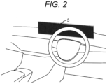
- the display unit 5 is a display device having a horizontally long large display surface, and is disposed, for example, on a dashboard of an automobile as illustrated in Fig. 2 .
- the first video source device 1 is, for example, a video player or the like, and the rendering unit 41 of the display control system 4 generates, for example, a first screen representing the video output from the first video source device 1 as illustrated in Fig. 3al .
- the second video source device 2 is, for example, a camera that captures an image of the rear side of the automobile, and the rendering unit 41 of the display control system 4 generates, for example, a second screen representing the video output from the second video source device 2 as illustrated in Fig. 3a2 .
- the data device 3 outputs, for example, data representing various states such as a vehicle speed of an automobile and a rotation speed of an engine to the display control system 4, and the rendering unit 41 of the display control system 4 generates, for example, a third screen imitating a meter cluster as illustrated in Fig. 3a3 from the data output from the data device 1.
- the displaying unit 42 of the display control system 4 combines the first screen, the second screen, and the third screen generated by the rendering unit so as to be aligned in the horizontal direction, and displays the combined screens on the display unit 5.
- the second screen and the third screen are screens of a functional safety target for performing black screen display when an abnormality such as a failure related to the screen occurs.
- the displaying unit 42 has a function of displaying the layer BL of the black screen in an overlapping manner on the second screen generated by the rendering unit 41, and by displaying the layer BL of the black screen in an overlapping manner, the second screen is displayed as the black screen as illustrated in Fig. 3c2 .
- the displaying unit 42 has a function of displaying the layer BL of the black screen on the third screen generated by the rendering unit 41 in an overlapping manner independently of a function of displaying the layer BL of the black screen on the second screen in an overlapping manner, and the third screen is displayed in the black screen as illustrated in Fig. 3d2 by displaying the layer BL of the black screen in an overlapping manner.
- the display control system 4 includes the timer counter circuit 44 corresponding to the second screen and the timer counter circuit 44 corresponding to the third screen.
- the abnormality monitoring unit 43 performs detection for abnormality/normality of the second video source device 2 and the rendering unit 41 related to the second screen, and in a case where the normality is detected, notifies the timer counter circuit 44 corresponding to the second screen of the normality detection.
- the abnormality monitoring unit 43 performs detection for the abnormality/normality of the data device 3 and the rendering unit 41 related to the third screen, and in a case where the normality is detected, notifies the timer counter circuit 44 corresponding to the third screen of the normality detection.
- the displaying unit 42 overlaps the black screen layer BL on the second screen and displays the same on the display unit 5.
- the displaying unit 42 displays the second screen generated by the rendering unit on the display unit 5 as it is.
- the displaying unit 42 overlaps the black screen layer BL on the third screen and displays the same on the display unit 5.
- the displaying unit 42 displays the third screen generated by the rendering unit on the display unit 5 as it is.
- the timer counter circuit 44 is a counter that counts up a count value TCNT by a clock of a constant cycle, and the count value TCNT is reset when the abnormality monitoring unit 43 notifies normality detection and when the count value TCNT reaches the value Th.
- the timer counter circuit 44 sets the black screen layer OFF of the corresponding screen in the displaying unit 42 when being reset by the notification of the normality detection before the count value TCNT reaches a value Th. Further, when the count value TCNT reaches the value Th and is reset, the timer counter circuit 44 sets the displaying unit 42 to turn on the black screen layer of the corresponding screen.
- the abnormality monitoring unit 43 is configured to repeatedly detect abnormality/normality related to the corresponding screen at a time interval shorter than the time required for the timer counter circuit 44 to count the count value TCNT from 0 to the value Th.
- the second screen turns on the black screen layer by default at the time of activation to display a black screen, and counting-up of the count value TCNT of the timer counter circuit 44 corresponding to the second screen is started.
- the abnormality monitoring unit 43 notifies normality detection at time t1 before the count value TCNT of the timer counter circuit 44 corresponding to the second screen reaches the value Th, the count value TCNT of the timer counter circuit 44 corresponding to the second screen is reset to 0, the black screen layer OFF of the second screen is set, the black screen display is released, and the second screen generated by the rendering unit 41 is displayed on the display unit 5.
- the timer counter circuit 44 corresponding to the second screen starts counting up the count value TCNT from 0 and the abnormality monitoring unit 43 notifies normality detection at time t2 before the count value TCNT reaches the value Th, the count value TCNT of the timer counter circuit 44 corresponding to the second screen is reset to 0, the black screen layer being OFF for the second screen is set, and the display of the second screen generated by the rendering unit 41 on the display unit 5 is maintained.
- the timer counter circuit 44 corresponding to the second screen starts counting up the count value TCNT from 0 and the count value TCNT reaches the value Th without receiving the notification of the normality detection from the abnormality monitoring unit 43 at time t3
- the count value TCNT of the timer counter circuit 44 is reset to 0, the black screen layer of the second screen is set to ON, and the second screen is displayed in black screen.
- the timer counter circuit 44 corresponding to the second screen starts counting up the count value TCNT from 0, and when the count value TCNT reaches the value Th again at time t4 without receiving the notification of the normality detection from the abnormality monitoring unit 43, the count value TCNT of the timer counter circuit 44 is reset to 0, the black screen layer ON of the second screen is set, and the black screen display of the second screen is maintained.
- the timer counter circuit 44 corresponding to the second screen starts counting up the count value TCNT from 0 and the abnormality monitoring unit 43 notifies normality detection at time t5 before the count value TCNT of the timer counter circuit 44 corresponding to the second screen reaches the value Th, the count value TCNT of the timer counter circuit 44 corresponding to the second screen is reset to 0, the black screen layer OFF of the second screen is set, the black screen display is released, and the second screen generated by the rendering unit 41 is displayed on the display unit 5.
- the black screen display of the second screen is maintained until normality of each unit related to the second screen is detected by the abnormality monitoring unit 43, and after the normality is detected, the display of the second screen generated by the rendering unit 41 on the display unit 5 is started.
- the abnormality monitoring unit 43 detects normality of each unit related to the second screen at a time interval shorter than a predetermined time required for the timer counter circuit 44 to count up from 0 to the count value TCNT, the display of the second screen generated by the rendering unit 41 on the display unit 5 is continued, and when the abnormality monitoring unit 43 cannot detect normality of each unit related to the second screen at a time interval shorter than a predetermined time, the display of the second screen transitions to black screen display, and the black screen display is maintained until normality of each unit related to the second screen is detected by the abnormality monitoring unit 43.
- the black screen display can be performed for each screen.
- black screen display is performed not at the time of abnormality detection but when normal cannot be detected at a time interval shorter than a predetermined time, the black screen display is performed even in a case where a failure occurs in the abnormality detection function itself, and reliability of functional safety can be improved.
- timer counter circuit 44 can be mounted on the display control system 4 as independently operable hardware, and by doing so, more reliable functional safety can be realized.
- Fig. 5 illustrates the configuration of a display system according to the second embodiment.
- the display system according to the second embodiment is different from the display system according to the first embodiment illustrated in Fig. 1 only in the configuration of the display control system.
- the display system 4 includes a first subsystem 410 and a second subsystem 420.
- the first subsystem 410 and the second subsystem 420 are systems built on different virtual machines on a hypervisor or on different CPUs.
- the first subsystem 410 includes the rendering unit 41 and the displaying unit 42 described in the first embodiment.
- the first subsystem 410 executes an abnormality monitoring task 4101 corresponding to the second screen and an abnormality monitoring task 4101 corresponding to the third screen.
- the second subsystem 421 executes a black screen layer control task 4201 corresponding to the second screen and the black screen layer control task 4201 corresponding to the third screen.
- the abnormality monitoring task 4101 corresponding to the second screen performs detection for the abnormality/normality of the second video source device 2 and the rendering unit 41 related to the second screen (step 602), and repeatedly performs processing of setting the abnormal flag to 0 (step 604) when the normality is detected.
- the black screen layer control task 4201 corresponding to the second screen sets the abnormal flag to 1 (step 652). Then, it is checked whether the abnormal flag is 0 (step 654).
- the black screen layer OFF of the second screen is set (step 656), and the abnormal flag is set to 1 (step 658). If the abnormal flag is not 0 but 1, the black screen layer ON of the second screen is set (step 660), and the abnormal flag is set to 1 (step 658).
- step 658 when the abnormal flag is set to 1 in step 658, the processing waits for the elapse of a predetermined time (for example, 15 ms) (step 662), and returns to the processing from step 654.
- a predetermined time for example, 15 ms
- the abnormality monitoring task 4101 is configured to repeatedly perform detection of abnormality/normality related to the corresponding screen at a time interval shorter than a predetermined time for waiting for elapse in step 662 of the black screen layer control task 4201.
- the black screen display of the second screen is controlled as follows.
- the black screen display is turned on by default and the black screen is displayed.
- the abnormal flag is set to 1 by the black screen layer control task 4201 at the time of activation (step 652)
- the black screen layer ON is continuously set (step 660) and the black screen display of the second screen is maintained until normality of each unit related to the second screen is detected by the abnormality monitoring task 4101 and the abnormal flag is set to 0.
- step 654 when normality of each unit related to the second screen is detected by the abnormality monitoring task 4101 and the abnormal flag is set to 0 (step 654), the black screen layer OFF is set (step 656), the black screen display is released, and the second screen generated by the rendering unit 41 is displayed on the display unit 5.
- the abnormal flag is set again to 1 (step 658), and after a predetermined time elapses (step 662), the black screen layer OFF setting (step 656) and the black screen layer ON setting (step 660) according to the value of the abnormal flag are performed again.
- the black screen layer ON is set (step 660) and the black screen display of the second screen is performed.
- step 662 when normality of each unit related to the second screen is detected by the abnormality monitoring task 4101 and the abnormal flag is set to 0 during the lapse of the predetermined time (step 662), the black screen layer OFF is set (step 656), and the display of the second screen generated by the rendering unit 41 on the display unit 5 is maintained.
- the black screen display of the second screen is maintained until normality of each unit related to the second screen is detected by the abnormality monitoring task 4101, and after the normality is detected, the display of the second screen generated by the rendering unit 41 on the display unit 5 is started.
- the display of the second screen generated by the rendering unit 41 on the display unit 5 continues, and when the normality of each unit related to the second screen cannot be detected at a time interval shorter than the predetermined time by the abnormality monitoring task 4101, the display of the second screen transitions to black screen display, and is maintained until the normality of each unit related to the second screen is detected by the abnormality monitoring task 4101.
- the black screen display can be performed for each screen.
- black screen display is performed not at the time of abnormality detection but when normal cannot be detected at a time interval shorter than a predetermined time, the black screen display is performed even in a case where a failure occurs in the abnormality detection function itself, and reliability of functional safety can be improved.
- the abnormality monitoring task 4101 for detecting an abnormality and the black screen layer control task 4201 for controlling black screen display are mounted on different virtual machines on the hypervisor or different subsystems constructed on different CPUs, more reliable functional safety can be realized.
- the black screen display of the screen is performed by overlapping and displaying the black screen display on the screen in the displaying unit 42, but the black screen display of the screen may be performed by another method.
- the black screen display of the screen may be performed by masking pixel data representing a color such as RGB of pixels constituting the screen output from the rendering unit 41 and outputting black pixel data.
- the above embodiments can also be similarly applied to a case where the display control system 4 performs display on a plurality of display units 5.
Landscapes
- Engineering & Computer Science (AREA)
- Theoretical Computer Science (AREA)
- Physics & Mathematics (AREA)
- General Physics & Mathematics (AREA)
- Computer Hardware Design (AREA)
- General Engineering & Computer Science (AREA)
- Quality & Reliability (AREA)
- Health & Medical Sciences (AREA)
- Biomedical Technology (AREA)
- General Health & Medical Sciences (AREA)
- Multimedia (AREA)
- Signal Processing (AREA)
- Controls And Circuits For Display Device (AREA)
Abstract
Description
- The present invention relates to a display system, which may be mounted on an automobile.
- As a display system mounted on an automobile, a display system that displays a plurality of screens on a horizontally long display side by side in a horizontal direction is known (for example,
JP 2007-292812 A - In a display system mounted on an automobile, when an abnormality such as a failure occurs, it is preferable to realize functional safety in which a screen related to the abnormality is displayed in black.
- However, in a display system that displays a plurality of screens on one display, when the entire surface of the display screen of the display is set to black screen display by turning off the backlight of the display or the like, a screen that is not abnormal or a screen that is not a functional safety target is also set to black screen display, which is not preferable.
- If a processing unit that performs rendering processing for a screen related to an abnormality is caused to render a black screen as a screen, only the screen related to the abnormality can be made a black screen. However, since the rendering processing for the screen is normally realized by software processing, this is not necessarily sufficient in reliability of functional safety.
- Further, in the processing of displaying a screen related to an abnormality in black when an abnormality is detected, when a failure or the like occurs in the processing unit itself that detects the abnormality, the screen related to an abnormality cannot be reliably displayed in black.
- Therefore, an object of the present invention is to reliably display only a screen related to an abnormality such as a failure as a black screen when an abnormality occurs in a display system that displays a plurality of screens on one display.
- The invention relates to a display system according to the appended claims. Embodiments are disclosed in the dependent claims.
- According to an aspect, the present invention provides a display system that displays a plurality of different screens on one display, the display system including a rendering unit that renders each of the plurality of screens, a display unit that arranges the screens drawn by the rendering unit and displays the screens on the display, a black screen display control unit, and an abnormality monitoring unit that performs detection for an abnormality related to a target screen for at least one screen as the target screen, and outputs normality detection to the black screen display control unit when no abnormality is detected. The black screen display control unit sets, on the display unit, a black screen being ON for a target for which normality detection is no longer being output at a time interval shorter than a predetermined time interval from the abnormality monitoring unit, and the display unit displays a black screen of the target screen for which a black screen being ON is set.
- The display system may be configured to cause the black screen display control unit to set a black screen being OFF for a target screen for which the normality detection is being output from the abnormality monitoring unit, and for the target screen on which a black screen being OFF is set, to cause the display unit to display the target screen on the display without displaying the black screen of the target screen.
- According to an embodiment, the display system may be configured such that, when the operation of the display system is started, a black screen being ON is set as an initial value on each of the target screens.
- According to an embodiment, the display system may be configured such that the black screen display control unit includes a timer counter corresponding to each target screen, each timer counter is reset when normality detection of a corresponding target screen has been output, and when counting has proceeded to a predetermined value, and sets a black screen being OFF for the corresponding target screen on the display unit when the normality detection of the corresponding target screen has been output, and sets a black screen being ON for the corresponding target screen on the display unit when counting has proceeded to the predetermined value, and the abnormality monitoring unit performs detection for an abnormality related to each target screen at a time interval shorter than a time required for the timer counter to count from 0 to the predetermined value, and outputs normality detection to the black screen display control unit when no abnormality is detected.
- According to an embodiment, the display system may further include an abnormal flag corresponding to each target screen, and the abnormality monitoring unit may set the abnormal flag corresponding to a target screen in which no abnormality has been detected to a first value to output the normality detection of the target screen to the black screen display control unit, and the black screen display control unit may execute a task corresponding to each target screen. Here, each task repeatedly performs processing of inquiring a value of the abnormal flag corresponding to the corresponding target screen, setting a black screen being OFF for the corresponding target screen on the display unit when the abnormal flag is the first value, or else setting a second value to the abnormality flag, and setting a black screen being ON for the corresponding target screen on the display unit when the abnormal flag is the second value at predetermined time intervals. In addition, the abnormality monitoring unit performs detection for an abnormality related to each target screen at a time interval shorter than the predetermined time, and sets an abnormal flag corresponding to a target screen in which no abnormality has been detected to a first value.
- According to an embodiment, the display system may be configured such that, for the target screens on which the black screen being ON is set, the display unit overlaps a layer of the black screen on the target image and displays the overlapped layers on the display to perform black screen display on the target screen.
- Further, according to an embodiment, the black screen display control unit is preferably operated on an operation base different from that of at least the rendering unit and the abnormality monitoring unit.
- Furthermore, according to an embodiment, the display system may be an in-vehicle display system mounted on an automobile.
- According to a display system according to the invention, in a display system that arranges and displays a plurality of screens on a single display, black screen display can be performed for each screen.
- In addition, since black screen display is performed not at the time of abnormality detection but when normal cannot be detected at a time interval shorter than a predetermined time, the black screen display is performed even in a case where a failure occurs in the abnormality detection function itself, and reliability of functional safety can be improved.
- As described above, according to the present invention, when an abnormality such as a failure occurs in a display system that displays a plurality of screens on one display, only a screen related to the abnormality can be reliably displayed in black.
-
Fig. 1 is a block diagram that illustrates the configuration of a display system according to a first embodiment of the present invention. -
Fig. 2 is a view illustrating an arrangement of a display according to the first embodiment of the present invention. -
Fig. 3 is a diagram illustrating functions of a rendering unit and a displaying unit according to the first embodiment of the present invention. -
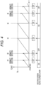
Fig. 4 is a diagram illustrating a control operation of black screen display according to the first embodiment of the present invention. -
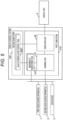
Fig. 5 is a block diagram that illustrates the configuration of a display system according to a second embodiment of the present invention. -
Fig. 6 is a diagram illustrating a control operation of black screen display according to the second embodiment of the present invention. - Hereinafter, embodiments of the invention will be described.
- First, a first embodiment will be described.
-
Fig. 1 illustrates a configuration of a display system according to the first embodiment. - As illustrated, the display system includes a first
video source device 1, a secondvideo source device 2, adata device 3, adisplay control system 4, and adisplay unit 5. - The
display control system 4 is a system configured as, for example, a system on a chip (SoC), and includes arendering unit 41, a displayingunit 42, anabnormality monitoring unit 43, and atimer counter circuit 44. - The
display unit 5 is a display device having a horizontally long large display surface, and is disposed, for example, on a dashboard of an automobile as illustrated inFig. 2 . - The first
video source device 1 is, for example, a video player or the like, and therendering unit 41 of thedisplay control system 4 generates, for example, a first screen representing the video output from the firstvideo source device 1 as illustrated inFig. 3al . - The second
video source device 2 is, for example, a camera that captures an image of the rear side of the automobile, and therendering unit 41 of thedisplay control system 4 generates, for example, a second screen representing the video output from the secondvideo source device 2 as illustrated inFig. 3a2 . - The
data device 3 outputs, for example, data representing various states such as a vehicle speed of an automobile and a rotation speed of an engine to thedisplay control system 4, and therendering unit 41 of thedisplay control system 4 generates, for example, a third screen imitating a meter cluster as illustrated inFig. 3a3 from the data output from thedata device 1. - Then, as illustrated in
Fig. 3b , the displayingunit 42 of thedisplay control system 4 combines the first screen, the second screen, and the third screen generated by the rendering unit so as to be aligned in the horizontal direction, and displays the combined screens on thedisplay unit 5. - Here, the second screen and the third screen are screens of a functional safety target for performing black screen display when an abnormality such as a failure related to the screen occurs.
- Next, as illustrated in
Fig. 3c1 , the displayingunit 42 has a function of displaying the layer BL of the black screen in an overlapping manner on the second screen generated by therendering unit 41, and by displaying the layer BL of the black screen in an overlapping manner, the second screen is displayed as the black screen as illustrated inFig. 3c2 . - Similarly, as illustrated in
Fig. 3d1 , the displayingunit 42 has a function of displaying the layer BL of the black screen on the third screen generated by therendering unit 41 in an overlapping manner independently of a function of displaying the layer BL of the black screen on the second screen in an overlapping manner, and the third screen is displayed in the black screen as illustrated inFig. 3d2 by displaying the layer BL of the black screen in an overlapping manner. - Next, the
display control system 4 includes thetimer counter circuit 44 corresponding to the second screen and thetimer counter circuit 44 corresponding to the third screen. - The
abnormality monitoring unit 43 performs detection for abnormality/normality of the secondvideo source device 2 and therendering unit 41 related to the second screen, and in a case where the normality is detected, notifies thetimer counter circuit 44 corresponding to the second screen of the normality detection. - In addition, the
abnormality monitoring unit 43 performs detection for the abnormality/normality of thedata device 3 and therendering unit 41 related to the third screen, and in a case where the normality is detected, notifies thetimer counter circuit 44 corresponding to the third screen of the normality detection. - An operation of the black screen control in such a display system will be described below.
- When the black screen layer ON of the second screen is set in the displaying
unit 42 and the black screen layer ON of the second screen is set in the default state at the time of activation of the display system, the displayingunit 42 overlaps the black screen layer BL on the second screen and displays the same on thedisplay unit 5. In addition, when the black screen layer OFF of the second screen is set, the displayingunit 42 displays the second screen generated by the rendering unit on thedisplay unit 5 as it is. - In addition, similarly, when the black screen layer ON of the third screen is set in the displaying
unit 42 and the black screen layer ON of the third screen is set in the default state at the time of activation of the display system, the displayingunit 42 overlaps the black screen layer BL on the third screen and displays the same on thedisplay unit 5. In addition, when the black screen layer OFF of the third screen is set, the displayingunit 42 displays the third screen generated by the rendering unit on thedisplay unit 5 as it is. - Next, the operation of each
timer counter circuit 44 will be described. - The
timer counter circuit 44 is a counter that counts up a count value TCNT by a clock of a constant cycle, and the count value TCNT is reset when theabnormality monitoring unit 43 notifies normality detection and when the count value TCNT reaches the value Th. - In addition, the
timer counter circuit 44 sets the black screen layer OFF of the corresponding screen in the displayingunit 42 when being reset by the notification of the normality detection before the count value TCNT reaches a value Th. Further, when the count value TCNT reaches the value Th and is reset, thetimer counter circuit 44 sets the displayingunit 42 to turn on the black screen layer of the corresponding screen. - Here, the
abnormality monitoring unit 43 is configured to repeatedly detect abnormality/normality related to the corresponding screen at a time interval shorter than the time required for thetimer counter circuit 44 to count the count value TCNT from 0 to the value Th. - Since the procedure of controlling the black screen display on the second screen and the third screen, which are the screens of the functional safety target, is the same, a specific example of the above operation of the
timer counter circuit 44 is illustrated inFig. 4 with the second screen as a representative example. - As illustrated in
Fig. 4 , the second screen turns on the black screen layer by default at the time of activation to display a black screen, and counting-up of the count value TCNT of thetimer counter circuit 44 corresponding to the second screen is started. - Then, when the
abnormality monitoring unit 43 notifies normality detection at time t1 before the count value TCNT of thetimer counter circuit 44 corresponding to the second screen reaches the value Th, the count value TCNT of thetimer counter circuit 44 corresponding to the second screen is reset to 0, the black screen layer OFF of the second screen is set, the black screen display is released, and the second screen generated by therendering unit 41 is displayed on thedisplay unit 5. - Then, when the
timer counter circuit 44 corresponding to the second screen starts counting up the count value TCNT from 0 and theabnormality monitoring unit 43 notifies normality detection at time t2 before the count value TCNT reaches the value Th, the count value TCNT of thetimer counter circuit 44 corresponding to the second screen is reset to 0, the black screen layer being OFF for the second screen is set, and the display of the second screen generated by therendering unit 41 on thedisplay unit 5 is maintained. - Then, when the
timer counter circuit 44 corresponding to the second screen starts counting up the count value TCNT from 0 and the count value TCNT reaches the value Th without receiving the notification of the normality detection from theabnormality monitoring unit 43 at time t3, the count value TCNT of thetimer counter circuit 44 is reset to 0, the black screen layer of the second screen is set to ON, and the second screen is displayed in black screen. - Then, the
timer counter circuit 44 corresponding to the second screen starts counting up the count value TCNT from 0, and when the count value TCNT reaches the value Th again at time t4 without receiving the notification of the normality detection from theabnormality monitoring unit 43, the count value TCNT of thetimer counter circuit 44 is reset to 0, the black screen layer ON of the second screen is set, and the black screen display of the second screen is maintained. - Then, when the
timer counter circuit 44 corresponding to the second screen starts counting up the count value TCNT from 0 and theabnormality monitoring unit 43 notifies normality detection at time t5 before the count value TCNT of thetimer counter circuit 44 corresponding to the second screen reaches the value Th, the count value TCNT of thetimer counter circuit 44 corresponding to the second screen is reset to 0, the black screen layer OFF of the second screen is set, the black screen display is released, and the second screen generated by therendering unit 41 is displayed on thedisplay unit 5. - As a result, after the display system is started, the black screen display of the second screen is maintained until normality of each unit related to the second screen is detected by the
abnormality monitoring unit 43, and after the normality is detected, the display of the second screen generated by therendering unit 41 on thedisplay unit 5 is started. Thereafter, while theabnormality monitoring unit 43 detects normality of each unit related to the second screen at a time interval shorter than a predetermined time required for thetimer counter circuit 44 to count up from 0 to the count value TCNT, the display of the second screen generated by therendering unit 41 on thedisplay unit 5 is continued, and when theabnormality monitoring unit 43 cannot detect normality of each unit related to the second screen at a time interval shorter than a predetermined time, the display of the second screen transitions to black screen display, and the black screen display is maintained until normality of each unit related to the second screen is detected by theabnormality monitoring unit 43. - The first embodiment of the invention has been described as above.
- As described above, according to the first embodiment, in the display system that displays a plurality of screens side by side on a
single display unit 5, the black screen display can be performed for each screen. - In addition, since black screen display is performed not at the time of abnormality detection but when normal cannot be detected at a time interval shorter than a predetermined time, the black screen display is performed even in a case where a failure occurs in the abnormality detection function itself, and reliability of functional safety can be improved.
- In addition, the
timer counter circuit 44 can be mounted on thedisplay control system 4 as independently operable hardware, and by doing so, more reliable functional safety can be realized. - Hereinafter, a second embodiment of the present invention will be described.
-
Fig. 5 illustrates the configuration of a display system according to the second embodiment. - The display system according to the second embodiment is different from the display system according to the first embodiment illustrated in
Fig. 1 only in the configuration of the display control system. - As illustrated, the
display system 4 according to the second embodiment includes afirst subsystem 410 and asecond subsystem 420. - The
first subsystem 410 and thesecond subsystem 420 are systems built on different virtual machines on a hypervisor or on different CPUs. - The
first subsystem 410 includes therendering unit 41 and the displayingunit 42 described in the first embodiment. Thefirst subsystem 410 executes anabnormality monitoring task 4101 corresponding to the second screen and anabnormality monitoring task 4101 corresponding to the third screen. - Then, similarly to the first embodiment, assuming that the second screen and the third screen are functional safety target screens, the second subsystem 421 executes a black screen
layer control task 4201 corresponding to the second screen and the black screenlayer control task 4201 corresponding to the third screen. - Since the procedure of controlling black screen display on the second screen and the third screen, which are screens targeted for functional safety, is the same, the operation of black screen display will be described below with the second screen as a representative example.
- As illustrated in
Fig. 6a , during the operation of the display system, theabnormality monitoring task 4101 corresponding to the second screen performs detection for the abnormality/normality of the secondvideo source device 2 and therendering unit 41 related to the second screen (step 602), and repeatedly performs processing of setting the abnormal flag to 0 (step 604) when the normality is detected. - As illustrated in
Fig. 6b , when the display system is activated, the black screenlayer control task 4201 corresponding to the second screen sets the abnormal flag to 1 (step 652). Then, it is checked whether the abnormal flag is 0 (step 654). - Then, if the abnormal flag is 0, the black screen layer OFF of the second screen is set (step 656), and the abnormal flag is set to 1 (step 658). If the abnormal flag is not 0 but 1, the black screen layer ON of the second screen is set (step 660), and the abnormal flag is set to 1 (step 658).
- Then, when the abnormal flag is set to 1 in
step 658, the processing waits for the elapse of a predetermined time (for example, 15 ms) (step 662), and returns to the processing fromstep 654. - Here, the
abnormality monitoring task 4101 is configured to repeatedly perform detection of abnormality/normality related to the corresponding screen at a time interval shorter than a predetermined time for waiting for elapse instep 662 of the black screenlayer control task 4201. - According to the operation of the black screen
layer control task 4201, the black screen display of the second screen is controlled as follows. - That is, when the second screen is activated, the black screen display is turned on by default and the black screen is displayed. In addition, since the abnormal flag is set to 1 by the black screen
layer control task 4201 at the time of activation (step 652), the black screen layer ON is continuously set (step 660) and the black screen display of the second screen is maintained until normality of each unit related to the second screen is detected by theabnormality monitoring task 4101 and the abnormal flag is set to 0. - On the other hand, when normality of each unit related to the second screen is detected by the
abnormality monitoring task 4101 and the abnormal flag is set to 0 (step 654), the black screen layer OFF is set (step 656), the black screen display is released, and the second screen generated by therendering unit 41 is displayed on thedisplay unit 5. - After the black screen layer OFF is set (step 658), the abnormal flag is set again to 1 (step 658), and after a predetermined time elapses (step 662), the black screen layer OFF setting (step 656) and the black screen layer ON setting (step 660) according to the value of the abnormal flag are performed again.
- Therefore, when normality of each unit related to the second screen is detected by the
abnormality monitoring task 4101 and the abnormal flag is not set to 0 during the lapse of the predetermined time (step 662), the black screen layer ON is set (step 660) and the black screen display of the second screen is performed. - On the other hand, when normality of each unit related to the second screen is detected by the
abnormality monitoring task 4101 and the abnormal flag is set to 0 during the lapse of the predetermined time (step 662), the black screen layer OFF is set (step 656), and the display of the second screen generated by therendering unit 41 on thedisplay unit 5 is maintained. - As a result, after the display system is started, the black screen display of the second screen is maintained until normality of each unit related to the second screen is detected by the
abnormality monitoring task 4101, and after the normality is detected, the display of the second screen generated by therendering unit 41 on thedisplay unit 5 is started. Thereafter, while the normality of each unit related to the second screen is detected at a time interval shorter than the predetermined time by theabnormality monitoring task 4101, the display of the second screen generated by therendering unit 41 on thedisplay unit 5 continues, and when the normality of each unit related to the second screen cannot be detected at a time interval shorter than the predetermined time by theabnormality monitoring task 4101, the display of the second screen transitions to black screen display, and is maintained until the normality of each unit related to the second screen is detected by theabnormality monitoring task 4101. - As described above, according to the second embodiment, in the display system that displays the screens of the number of single display unit side by side, the black screen display can be performed for each screen.
- In addition, since black screen display is performed not at the time of abnormality detection but when normal cannot be detected at a time interval shorter than a predetermined time, the black screen display is performed even in a case where a failure occurs in the abnormality detection function itself, and reliability of functional safety can be improved. In addition, since the
abnormality monitoring task 4101 for detecting an abnormality and the black screenlayer control task 4201 for controlling black screen display are mounted on different virtual machines on the hypervisor or different subsystems constructed on different CPUs, more reliable functional safety can be realized. - In the above embodiments, the black screen display of the screen is performed by overlapping and displaying the black screen display on the screen in the displaying
unit 42, but the black screen display of the screen may be performed by another method. For example, in the displayingunit 42, the black screen display of the screen may be performed by masking pixel data representing a color such as RGB of pixels constituting the screen output from therendering unit 41 and outputting black pixel data. - The above embodiments can also be similarly applied to a case where the
display control system 4 performs display on a plurality ofdisplay units 5. -
- 1
- First video source device
- 2
- Second video source device
- 3
- Data device
- 4
- Display control system
- 5
- Display unit
- 41
- Rendering unit
- 42
- Displaying unit
- 43
- Abnormality monitoring unit
- 44
- Timer counter circuit
- 410
- First subsystem
- 420
- Second subsystem
- 4101
- Abnormality monitoring task
- 4201
- Black screen layer control task
Claims (8)
- A display system configured to display a plurality of different screens on one display, the display system comprising:a rendering unit (41) configured to render each of the plurality of screens; anda display unit (5) that is configured to arrange a screen drawn by the rendering unit (41) and to display the screen on the display;a black screen display control unit; andan abnormality monitoring unit (43) configured to repeatedly detect an abnormality related to at least one screen as a target screen for each target screen, and output normality detection to the black screen display control unit when no abnormality is detected, characterized in thatthe black screen display control unit is configured to set, on the display unit (5), a black screen being ON of a target for which normality detection is no longer output at a time interval shorter than a predetermined time from an abnormality monitoring unit (43), andthe display unit (5) is configured to perform black screen display of a target screen on which a black screen being ON is set.
- The display system according to claim 1, whereinthe black screen display control unit is configured to set, on the display unit (5), a black screen being OFF of the target screen on which normality detection is output from the abnormality monitoring unit (43), andthe display unit (5) is configured to display the target screen set with the black screen OFF on the display without displaying a black screen of the target screen.
- The display system according to claim 2, wherein
when the operation of the display system is started, a black screen being ON is set as an initial value on each of the target screens. - The display system according to claim 2 or 3, whereinthe black screen display control unit includes a timer counter corresponding to each target screen,each timer counter is reset when normality detection of a corresponding target screen is output and when counting proceeds to a predetermined value, is configured to set a black screen being OFF for the corresponding target screen on the display unit (5) when the normality detection of the corresponding target screen is output, and is configured to set a black screen being ON for the corresponding target screen on the display unit (5) when the counting proceeds to the predetermined value, andthe abnormality monitoring unit (43) is configured to perform detection for an abnormality related to each target screen at a time interval shorter than a time required for the timer counter to count from 0 to the predetermined value, and to output normality detection to the black screen display control unit when no abnormality is detected.
- The display system according to claim 2 or 3, further comprising:an abnormal flag corresponding to each target screen, whereinthe abnormality monitoring unit (43) is configured to set the abnormal flag corresponding to a target screen in which no abnormality has been detected to a first value to output the normality detection of the target screen to the black screen display control unit,the black screen display control unit is configured to execute a task corresponding to each target screen,each task repeatedly performs processing of inquiring a value of the abnormal flag corresponding to the corresponding target screen, setting a black screen being OFF for the corresponding target screen on the display unit (5) and setting a second value to the abnormal flag when the abnormal flag is a first value, and setting a black screen being ON for the corresponding target screen on the display unit (5) when the abnormal flag is the second value at predetermined time intervals, andthe abnormality monitoring unit (43) is configured to perform detection for an abnormality related to each target screen at a time interval shorter than the predetermined time, and to set an abnormal flag corresponding to a target screen in which no abnormality has been detected to a first value.
- The display system according to claim 1, 2, 3, 4, or 5, wherein
for the target screen on which the black screen being ON is set, the display unit (5) is configured to overlap layers of the black screen on the target image and to display the overlapped layers on the display to perform black screen displaying of the target screen. - The display system according to claim 1, 2, 3, 4, 5, or 6, wherein
the black screen display control unit is configured to operate on an operation base different from that of at least the rendering unit (41) and the abnormality monitoring unit (43). - The display system according to claim 1, 2, 3, 4, 5, 6, or 7, wherein
the display system is an in-vehicle display system mounted on an automobile.
Applications Claiming Priority (1)
| Application Number | Priority Date | Filing Date | Title |
|---|---|---|---|
| JP2021178934A JP7612308B2 (en) | 2021-11-01 | 2021-11-01 | Display System |
Publications (1)
| Publication Number | Publication Date |
|---|---|
| EP4174830A1 true EP4174830A1 (en) | 2023-05-03 |
Family
ID=83692664
Family Applications (1)
| Application Number | Title | Priority Date | Filing Date |
|---|---|---|---|
| EP22201446.6A Pending EP4174830A1 (en) | 2021-11-01 | 2022-10-13 | Display system |
Country Status (4)
| Country | Link |
|---|---|
| US (1) | US12062306B2 (en) |
| EP (1) | EP4174830A1 (en) |
| JP (1) | JP7612308B2 (en) |
| CN (1) | CN116074497A (en) |
Cited By (1)
| Publication number | Priority date | Publication date | Assignee | Title |
|---|---|---|---|---|
| CN119590214A (en) * | 2024-11-28 | 2025-03-11 | 岚图汽车科技有限公司 | Method, device, equipment and storage medium for redundancy lighting of vehicle computer black screen software |
Families Citing this family (3)
| Publication number | Priority date | Publication date | Assignee | Title |
|---|---|---|---|---|
| JP2024116498A (en) * | 2023-02-16 | 2024-08-28 | セイコーエプソン株式会社 | Driver and electro-optical device |
| TWI864845B (en) * | 2023-06-27 | 2024-12-01 | 大陸商北京集創北方科技股份有限公司 | OSD pattern display method, electronic chip and information processing device |
| CN117615083B (en) * | 2023-11-14 | 2024-07-12 | 深圳市海威恒泰智能科技有限公司 | Visual interaction method of splicing processor |
Citations (4)
| Publication number | Priority date | Publication date | Assignee | Title |
|---|---|---|---|---|
| JP2007292812A (en) | 2006-04-20 | 2007-11-08 | Matsushita Electric Ind Co Ltd | Display device |
| US20200135153A1 (en) * | 2018-10-26 | 2020-04-30 | Seiko Epson Corporation | Display controller, display control system, electro-optical device, electronic apparatus, and mobile unit |
| US10705377B2 (en) * | 2018-06-29 | 2020-07-07 | Sharp Kabushiki Kaisha | Liquid crystal display device and method of controlling the same |
| WO2020230549A1 (en) * | 2019-05-16 | 2020-11-19 | 株式会社デンソー | Vehicular device |
Family Cites Families (3)
| Publication number | Priority date | Publication date | Assignee | Title |
|---|---|---|---|---|
| US9254750B2 (en) | 2010-02-23 | 2016-02-09 | Paccar Inc | Graphical display with scrollable graphical elements |
| US20160063659A1 (en) * | 2014-09-02 | 2016-03-03 | Apple Inc. | Electronic Device Display With Electrostatic Discharge Recovery Capabilities |
| DE102017200915A1 (en) * | 2017-01-20 | 2018-07-26 | Bayerische Motoren Werke Aktiengesellschaft | A method and apparatus for displaying an indication to a user and work device |
-
2021
- 2021-11-01 JP JP2021178934A patent/JP7612308B2/en active Active
-
2022
- 2022-10-13 EP EP22201446.6A patent/EP4174830A1/en active Pending
- 2022-10-25 US US17/972,829 patent/US12062306B2/en active Active
- 2022-10-31 CN CN202211346303.XA patent/CN116074497A/en active Pending
Patent Citations (5)
| Publication number | Priority date | Publication date | Assignee | Title |
|---|---|---|---|---|
| JP2007292812A (en) | 2006-04-20 | 2007-11-08 | Matsushita Electric Ind Co Ltd | Display device |
| US10705377B2 (en) * | 2018-06-29 | 2020-07-07 | Sharp Kabushiki Kaisha | Liquid crystal display device and method of controlling the same |
| US20200135153A1 (en) * | 2018-10-26 | 2020-04-30 | Seiko Epson Corporation | Display controller, display control system, electro-optical device, electronic apparatus, and mobile unit |
| WO2020230549A1 (en) * | 2019-05-16 | 2020-11-19 | 株式会社デンソー | Vehicular device |
| US20220075697A1 (en) * | 2019-05-16 | 2022-03-10 | Denso Corporation | Vehicular apparatus |
Cited By (1)
| Publication number | Priority date | Publication date | Assignee | Title |
|---|---|---|---|---|
| CN119590214A (en) * | 2024-11-28 | 2025-03-11 | 岚图汽车科技有限公司 | Method, device, equipment and storage medium for redundancy lighting of vehicle computer black screen software |
Also Published As
| Publication number | Publication date |
|---|---|
| US20230134109A1 (en) | 2023-05-04 |
| US12062306B2 (en) | 2024-08-13 |
| JP2023067562A (en) | 2023-05-16 |
| JP7612308B2 (en) | 2025-01-14 |
| CN116074497A (en) | 2023-05-05 |
Similar Documents
| Publication | Publication Date | Title |
|---|---|---|
| US12062306B2 (en) | Display system | |
| JP6658391B2 (en) | Video display system for vehicles | |
| EP3355188B1 (en) | Instrument display on a car dashboard by checking frames of a gui by a realtime os | |
| US11836056B2 (en) | Vehicular apparatus | |
| JP5733429B2 (en) | Information processing apparatus and information processing method | |
| US12103388B2 (en) | On-vehicle interface apparatus | |
| US20220073019A1 (en) | Vehicle device | |
| JP2022189714A (en) | Display device for vehicle | |
| US11971002B2 (en) | Vehicle electrical power system with defect detection | |
| JP5240007B2 (en) | Vehicle display device | |
| US10710536B1 (en) | Function safety system for vehicle malfunction display | |
| US20190385561A1 (en) | Method and device for operating a display | |
| US20140002272A1 (en) | Display device having a stepper motor and a watchdog timer | |
| CN113939807A (en) | Vehicle device | |
| JP7840105B2 (en) | Control device, control method, and program | |
| CN116844319B (en) | Vehicle fault alarm methods, devices, electronic equipment, storage media and vehicles | |
| US20250363813A1 (en) | Image processing apparatus, information processing system, information processing method, and non-transitory recording medium | |
| JP2024167720A (en) | Display Control Device | |
| US20260031004A1 (en) | Device and method for failure diagnosis of image processing devices | |
| KR200364450Y1 (en) | Variable message sign apparatus for being able to operate in an extraordinary condition | |
| JP2022158588A (en) | Display control device and display control method | |
| CN121996481A (en) | Method and device for controlling a display of a vehicle | |
| CN119626120A (en) | Display screen fault monitoring method, electronic device and vehicle | |
| JPS61282138A (en) | Failure diagnosis method for in-vehicle electronic equipment | |
| CN120765564A (en) | Image display method, device, equipment and storage medium |
Legal Events
| Date | Code | Title | Description |
|---|---|---|---|
| PUAI | Public reference made under article 153(3) epc to a published international application that has entered the european phase |
Free format text: ORIGINAL CODE: 0009012 |
|
| STAA | Information on the status of an ep patent application or granted ep patent |
Free format text: STATUS: THE APPLICATION HAS BEEN PUBLISHED |
|
| AK | Designated contracting states |
Kind code of ref document: A1 Designated state(s): AL AT BE BG CH CY CZ DE DK EE ES FI FR GB GR HR HU IE IS IT LI LT LU LV MC ME MK MT NL NO PL PT RO RS SE SI SK SM TR |
|
| STAA | Information on the status of an ep patent application or granted ep patent |
Free format text: STATUS: REQUEST FOR EXAMINATION WAS MADE |
|
| 17P | Request for examination filed |
Effective date: 20231102 |
|
| RBV | Designated contracting states (corrected) |
Designated state(s): AL AT BE BG CH CY CZ DE DK EE ES FI FR GB GR HR HU IE IS IT LI LT LU LV MC ME MK MT NL NO PL PT RO RS SE SI SK SM TR |
|
| STAA | Information on the status of an ep patent application or granted ep patent |
Free format text: STATUS: EXAMINATION IS IN PROGRESS |
|
| 17Q | First examination report despatched |
Effective date: 20250123 |