EP4174580A1 - Toner cartridge, method for detecting remaining amount of toner, and image forming device - Google Patents
Toner cartridge, method for detecting remaining amount of toner, and image forming device Download PDFInfo
- Publication number
- EP4174580A1 EP4174580A1 EP21860353.8A EP21860353A EP4174580A1 EP 4174580 A1 EP4174580 A1 EP 4174580A1 EP 21860353 A EP21860353 A EP 21860353A EP 4174580 A1 EP4174580 A1 EP 4174580A1
- Authority
- EP
- European Patent Office
- Prior art keywords
- toner
- detection unit
- current
- stirring
- toner cartridge
- Prior art date
- Legal status (The legal status is an assumption and is not a legal conclusion. Google has not performed a legal analysis and makes no representation as to the accuracy of the status listed.)
- Granted
Links
Images

Classifications
-
- G—PHYSICS
- G03—PHOTOGRAPHY; CINEMATOGRAPHY; ANALOGOUS TECHNIQUES USING WAVES OTHER THAN OPTICAL WAVES; ELECTROGRAPHY; HOLOGRAPHY
- G03G—ELECTROGRAPHY; ELECTROPHOTOGRAPHY; MAGNETOGRAPHY
- G03G15/00—Apparatus for electrographic processes using a charge pattern
- G03G15/06—Apparatus for electrographic processes using a charge pattern for developing
- G03G15/08—Apparatus for electrographic processes using a charge pattern for developing using a solid developer, e.g. powder developer
- G03G15/0822—Arrangements for preparing, mixing, supplying or dispensing developer
- G03G15/0848—Arrangements for testing or measuring developer properties or quality, e.g. charge, size, flowability
- G03G15/0856—Detection or control means for the developer level
-
- G—PHYSICS
- G03—PHOTOGRAPHY; CINEMATOGRAPHY; ANALOGOUS TECHNIQUES USING WAVES OTHER THAN OPTICAL WAVES; ELECTROGRAPHY; HOLOGRAPHY
- G03G—ELECTROGRAPHY; ELECTROPHOTOGRAPHY; MAGNETOGRAPHY
- G03G15/00—Apparatus for electrographic processes using a charge pattern
- G03G15/06—Apparatus for electrographic processes using a charge pattern for developing
- G03G15/08—Apparatus for electrographic processes using a charge pattern for developing using a solid developer, e.g. powder developer
- G03G15/0822—Arrangements for preparing, mixing, supplying or dispensing developer
- G03G15/0887—Arrangements for conveying and conditioning developer in the developing unit, e.g. agitating, removing impurities or humidity
- G03G15/0889—Arrangements for conveying and conditioning developer in the developing unit, e.g. agitating, removing impurities or humidity for agitation or stirring
-
- G—PHYSICS
- G03—PHOTOGRAPHY; CINEMATOGRAPHY; ANALOGOUS TECHNIQUES USING WAVES OTHER THAN OPTICAL WAVES; ELECTROGRAPHY; HOLOGRAPHY
- G03G—ELECTROGRAPHY; ELECTROPHOTOGRAPHY; MAGNETOGRAPHY
- G03G15/00—Apparatus for electrographic processes using a charge pattern
- G03G15/55—Self-diagnostics; Malfunction or lifetime display
- G03G15/553—Monitoring or warning means for exhaustion or lifetime end of consumables, e.g. indication of insufficient copy sheet quantity for a job
- G03G15/556—Monitoring or warning means for exhaustion or lifetime end of consumables, e.g. indication of insufficient copy sheet quantity for a job for toner consumption, e.g. pixel counting, toner coverage detection or toner density measurement
Definitions
- the present disclosure generally relates to the field of image-forming technology and, more particularly, relates to a toner cartridge, a method for detecting a remaining toner amount, and an image-forming apparatus.
- Image-forming apparatuses are indispensable office equipment in daily use. Toner is a required material for laser printers to complete smooth printing.
- toner is normally placed in the toner cartridge of the image-forming apparatus, and the user needs to remove the toner cartridge from the printer to check the remaining toner amount, which is inconvenient for the user.
- the user when performing printing through the image-forming apparatus, the user often encounters the situation that the printing is paused due to insufficient toner and may only temporarily find the toner for adding, which may waste the user's time and even delay the user's printing progress to cause huge loss.
- existing detection solutions of the toner in the toner cartridge may include optical toner detection, capacitive toner detection, and ultrasonic toner detection, which may be relatively expensive or have complex structures.
- another toner detection type for example, magnetic signal toner detection, may be only suitable for magnetic toner detection.
- insufficient toner may be detected by measuring the SR (supply roller) current, but the disadvantage of such solution is that when the toner is detected to be insufficient, the images may already have defects, and the user may not be reminded in advance.
- Embodiments of the present application provide a toner cartridge, a method for detecting a remaining toner amount, and an image-forming apparatus, which determine whether the toner cartridge has toner or is short of toner before the images have defects, and the detection process is relatively convenient with low detection cost.
- the first aspect of the present disclosure provides a toner cartridge.
- the toner cartridge is installed on an image-forming apparatus.
- the toner cartridge includes a toner hopper, configured to hold toner; a stirring unit, disposed in the toner hopper and configured to stir the toner in the toner hopper; and a detection unit, disposed on the stirring unit and configured to be in contact with the toner during a process of stirring the toner by the stirring unit and output a current signal.
- a housing of the toner cartridge is disposed with electrical connection contacts, and the detection unit is electrically connected to the image-forming apparatus through the electrical connection contacts.
- the image-forming apparatus includes a controller; the image-forming apparatus or the toner cartridge includes a current detection unit; and the current detection unit is electrically connected with the detection unit and the controller; and the current detection unit detects the current signal outputted by the detection unit and output a current detection result to the controller, such that the controller determines whether the toner cartridge is short of toner according to the current detection result.
- the stirring unit includes a stirring frame and a stirring frame blade which is disposed on a peripheral surface of the stirring frame; and the detection unit is disposed on the stirring frame blade.
- the detection unit is made of a conductive material and attached to the stirring frame blade; or the stirring frame blade itself is made of a conductive material.
- the second aspect of the present disclosure provides a method for detecting a remaining toner amount, applied to a toner cartridge.
- the toner cartridge is installed on an image-forming apparatus; a stirring unit is disposed in the toner cartridge; the image-forming apparatus or the toner cartridge includes a current detection unit; the image-forming apparatus includes a controller; a detection unit is disposed on the stirring unit and configured to be in contact with toner during a process of stirring the toner by the stirring unit and output a current signal; and the current detection unit is electrically connected to the detection unit and the controller.
- the method includes rotating the stirring unit to drive the detection unit to rotate, where the detection unit is in contact with the toner in the toner cartridge to generate the current signal, such that the current detection unit detects the current signal of the detection unit and outputs a current detection result to the controller; and the controller determines whether the toner cartridge is short of toner according to the current detection result.
- the stirring unit includes a stirring frame and a stirring frame blade which is disposed on a peripheral surface of the stirring frame; and the detection unit is disposed on the stirring frame blade.
- the detection unit is made of a conductive material and attached to the stirring frame blade; or the stirring frame blade itself is made of a conductive material.
- the third aspect of the present disclosure provides an image-forming apparatus.
- the image-forming apparatus includes a toner cartridge installed on the image-forming apparatus, where a stirring unit is disposed in the toner cartridge; and a detection unit is disposed on the stirring unit and configured to be in contact with toner during a process of stirring the toner by the stirring unit and output a current signal; a controller, configured to control the stirring unit to rotate and drive the detection unit to rotate when the image forming device executes a printing task; and a current detection unit, electrically connected to the detection unit and the controller and configured to detect the current signal of the detection unit and output a current detection result to the controller, where the controller determines whether the toner cartridge is short of toner according to the current detection result.
- the controller is configured to: during a rotating process of the stirring unit, if the current detection unit detects that an absolute value of a current signal of the detection unit is less than or equal to a first threshold for a duration exceeding a first preset time, determine that the toner cartridge is short of toner.
- the controller is configured to: during a rotating process of the stirring unit, if the current detection unit detects that a change process of a current of the detection unit is a first process, determine that the toner cartridge is not short of toner, wherein: the first process is that the current of the detection unit changes from a gradually increasing positive current to a gradually decreasing negative current wherein an absolute value of the negative current is greater than or equal to a second threshold.
- the fourth aspect of the present disclosure provides a method for detecting a remaining toner amount, applied to an image-forming apparatus.
- a toner cartridge is installed on the image-forming apparatus; a stirring unit is disposed in the toner cartridge; the image-forming apparatus includes a controller; the image-forming apparatus or the toner cartridge includes a current detection unit; a detection unit is disposed on the stirring unit and configured to be in contact with toner during a process of stirring the toner by the stirring unit and output a current signal; and the current detection unit is electrically connected to the detection unit and the controller.
- the method includes when the image forming device executes a printing task, controlling, by the controller, the stirring unit to rotate and drive the detection unit to rotate; detecting, by the current detection unit, the current signal of the detection unit and outputting a current detection result to the controller; and determining, by the controller, whether the toner cartridge is short of toner according to the current detection result.
- determining, by the controller, whether the toner cartridge is short of toner according to the current detection result includes: during a rotating process of the stirring unit, if the current detection unit detects that an absolute value of a current of the detection unit is less than or equal to a first threshold for a duration exceeding a first preset time, determining, by the controller, that the toner cartridge is short of toner.
- determining, by the controller, whether the toner cartridge is short of toner according to the current detection result includes: during a rotating process of the stirring unit, if the current detection unit detects that a change process of a current of the detection unit is a first process, determining, by the controller, that the toner cartridge is not short of toner, wherein: the first process is that the current of the detection unit changes from a gradually increasing positive current to a gradually decreasing negative current wherein an absolute value of the negative current is greater than or equal to a second threshold.
- the current detection unit may be disposed to detect the current of the detection unit which is disposed on the stirring unit and follows the rotation of the stirring unit, thereby determining whether the toner cartridge has toner or is short of toner according to the current detection result, which may have high detection accuracy and convenience, and have no need to manually open the toner cartridge to check.
- the current detection unit may determine whether the toner cartridge has toner or is short of toner before the toner in the toner cartridge is almost used up but there is no image defect, which may be convenient to remind the user to add toner or replace the toner cartridge in advance.
- "at least one” indicates one or more, and "a plurality of” indicates two or more.
- “And/or” describes the association relationship of associated objects, indicating that there can be three types of relationships. For example, A and/or B indicates that A exists alone, A and B exist at the same time, and B exists alone, where A and B may be singular or plural.
- the character “/” normally indicates that the contextual objects are an “or” relationship.
- “At least one of the following" or similar expressions indicate any combination of these items, including any combination of single or plural items.
- At least one of a, b, or c may indicate that a, b, c, a-b, a-c, b-c or a-b-c, where a, b, c are singular or plural.
- the image-forming apparatus is configured to perform image-forming jobs such as generating, printing, receiving and transmitting image data; and examples of the image-forming apparatus may include a printer, a scanner, a copier, a facsimile, and a MultiFunctional Peripheral (MFP) that performs above functions in a single device.
- image-forming jobs such as generating, printing, receiving and transmitting image data
- examples of the image-forming apparatus may include a printer, a scanner, a copier, a facsimile, and a MultiFunctional Peripheral (MFP) that performs above functions in a single device.
- MFP MultiFunctional Peripheral
- the image-forming apparatus may include a controller and an image-forming part.
- the controller may control the image data to be obtained by the image-forming part to form images on conveyed paper.
- the image-forming part may include an exposing assembly, a photosensitive drum (OPC, organic photoconductor), a charging roller, a developing roller, an intermediate transfer belt, a primary transfer roller, a secondary transfer roller, a fixing unit, a cleaning blade, and the like.
- OPC organic photoconductor
- the image-forming process of the image-forming part may include charging the surface of the organic photoconductor by the charging roller, generating an exposure signal according to the image data by the exposing assembly, emitting a laser beam corresponding to the exposure signal, and exposing the surface of the organic photoconductor, thereby forming an electrostatic latent image on the surface of the organic photoconductor.
- the developing roller develops the electrostatic latent image on the surface of the organic photoconductor into a toner image.
- the primary transfer roller transfers the toner image on the surface of the organic photoconductor to the surface of the intermediate transfer belt for the first transfer, thereby forming the toner image on the surface of the intermediate transfer belt.
- the secondary transfer roller transfers the toner image on the surface of the intermediate transfer belt to paper for the second transfer.
- the paper on which the toner image is secondarily transferred is conveyed into a fixing unit.
- the fixing unit fixes the toner image on the paper to be discharged.
- the toner remaining on the surface of the organic photoconductor is removed by the cleaning blade.
- the number of the above-mentioned exposing assemblies, organic photoconductors, charging rollers, developing rollers and the like may be 4 or more.
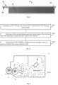
- FIG. 1 illustrates a structural schematic of a toner cartridge provided by exemplary embodiments of the present disclosure.
- a toner cartridge 1 may be an integrated toner cartridge or a split toner cartridge.
- the integrated toner cartridge may integrate the toner cartridge 1 and the organic photoconductor on a same apparatus. When the toner is used up or the organic photoconductor is damaged, the toner cartridge and the organic photoconductor may be replaced together. For the split toner cartridge, the organic photoconductor and toner cartridge may be separated to be not attached. When the toner is used up, it may only need to replace old toner cartridge with new toner cartridge; and as long as the lifespan of the toner cartridge has not reached, the split toner cartridge may continue to use.
- a toner cartridge 1 may be an integrated toner cartridge or a split toner cartridge.
- the toner cartridge 1 may include a developing roller (DR) 11, a supply roller (SR) 12, a toner hopper 13 and a stirring unit 14 disposed in the toner hopper 13.
- DR developing roller
- SR supply roller
- stirring unit 14 disposed in the toner hopper 13.
- the toner cartridge 1 may also include an organic photoconductor 15, a charging roller 16, and the like.
- the toner hopper 13 may be configured to store the toner for developing.
- the toner hopper 13 may have a toner output outlet for outputting toner.
- the stirring unit 14 may be configured to stir the toner in the toner hopper 13.
- the toner in the toner hopper 13 may be outputted to the supply roller 12 through the toner output outlet by stirring.
- the supply roller 12 may be disposed at the toner output outlet and configured to transfer the toner outputted from the toner output outlet to the developing roller 11.
- the developing roller 11 is applied with a developing bias voltage, the toner near the developing roller 11 may adhere to the region of the organic photoconductor 15 exposed by the exposing assembly, thereby developing the electrostatic latent image on the surface of the organic photoconductor 15 into the toner image.
- the toner cartridge 1 may further include structures such as a cleaning blade 17.
- the cleaning blade 17 may be disposed on the main body of the image-forming apparatus or in the toner cartridge 1.
- FIG. 2 illustrates a connection relationship schematic between a current detection unit and a detection unit provided by exemplary embodiments of the present disclosure.
- the stirring unit 14 may be disposed with a detection unit 18.
- the detection unit 18 may be disposed on the stirring unit 14 and configured to be in contact with the toner during the process of stirring the toner by the stirring unit 14 and output a current signal.
- the image-forming apparatus may include the controller; the image-forming apparatus or the toner cartridge 1 may include a current detection unit 3; and the current detection unit 3 may be electrically connected with the detection unit 18 and the controller 2.
- the current detection unit 3 may detect the current signal outputted by the detection unit 18 and output the current detection result to the controller 2, such that the controller 2 may determine whether the toner cartridge 1 is short of toner according to the current detection result.
- the housing of the toner cartridge 1 may be disposed with electrical connection contacts, and the detection unit 18 may be electrically connected with the image-forming apparatus through the electrical connection contacts.
- FIG. 3 illustrates a structural schematic of a stirring unit provided by exemplary embodiments of the present disclosure.
- the stirring unit 14 may include a stirring frame 141 and a stirring frame blade 142 disposed on the peripheral surface of the stirring frame 141.
- the stirring unit 14 may further include a stirring shaft 143, and the stirring shaft 143 may drive the stirring frame 141 to rotate, thereby driving the stirring frame blade 142 to rotate.
- the stirring frame blade 142 may be configured to have desirable stirring intensity to improve stirring quality.
- the detection unit 18 may be configured to be in contact (e.g., having friction) with the toner to generate the current signal.
- the detection unit 18 may be a conductive material, such as a copper sheet.
- the detection unit 18 may be attached to the stirring frame blade 142, which may be in desirable contact with the toner, thereby achieving desirable toner sensitivity.
- the detection unit 18 may also be a metal sheet having same or similar chemical properties as copper, for example, iron, aluminum or the like; or the detection unit 18 may also be an alloy which is made of copper combined with other metals, stainless steel or the like, which may not be limited according to embodiments of the present disclosure.
- the stirring frame blade 142 of the stirring unit 14 itself may also be a conductive material; or a conductive coating may be on the surface of the stirring frame blade, which may be used as the electrical connection between the detection unit 18 and the current detection unit.
- the controller 2 may control the stirring unit 14 to rotate under the driving source (not shown in drawings), for example, control the rotation of the stirring shaft 143 to drive the stirring frame 141 and the stirring frame blade 142.
- the stirring unit 14 may rotate along the W direction (clockwise) shown in FIG. 1 .
- Embodiments of the present disclosure provide a method for detecting the remaining toner amount.
- the method may be applied to the toner cartridge 1 and include following exemplary steps.
- the stirring unit may rotate to drive the detection unit to rotate; and the detection unit may be in contact with the toner in the toner cartridge to generate the current signal, such that the current detection unit may detect the current signal of the detection unit and output the current detection result to the controller, and the controller may determine whether the toner cartridge is short of toner according to the current detection result.
- the current detection unit may be disposed to detect the current signal of the detection unit which is disposed on the stirring unit and follows the rotation of the stirring unit, thereby determining whether the toner cartridge has toner or is short of toner according to the current detection result, which may have high detection accuracy and convenience, and have no need to manually open the toner cartridge to check.
- the current detection unit may be disposed to detect the current signal of the detection unit which is disposed on the stirring unit and follows the rotation of the stirring unit, thereby determining whether the toner cartridge has toner or is short of toner according to the current detection result, which may have high detection accuracy and convenience, and have no need to manually open the toner cartridge to check.
- relatively large amount of toner may be still on the developing roller and supply roller, which may ensure that white streaks phenomenon may not occur within a certain number of pages.
- the toner cartridge may determine whether the toner cartridge has toner or is short of toner before the toner in the toner cartridge is almost used up but there is no image defect, which may be convenient to remind the user to add toner or replace the toner cartridge in advance when printing errors (such as white streak phenomenon) occur.
- FIG. 4 illustrates a flowchart of a method for detecting the toner remaining amount provided by exemplary embodiments of the present disclosure.
- the method for detecting the remaining toner amount provided by the present disclosure, applied to the image-forming apparatus may include following exemplary steps.
- the controller may control the stirring unit to rotate and drive the detection unit to rotate.
- the current detection unit may detect the current signal of the detection unit and output the current detection result to the controller.
- the controller may determine whether the toner cartridge is short of toner according to the current detection result.
- Triggering the controller to detect the toner amount may be, but may not be limited, to any one or more of following cases: 1) The toner cartridge 1 is installed on the image-forming apparatus; 2) the image-forming apparatus is powered on or turned on; 3) before or after the print job is executed; 4) during the execution of the print task; and 5) receiving an instruction from the user to detect the remaining toner amount.
- the controller 2 of the image-forming apparatus may realize the detection of the remaining toner amount by rotating the stirring unit and driving the detecting unit to rotate.
- the controller 2 may prompt the user that current image-forming apparatus is in a state of lack of toner through the display unit (such as a display screen) and/or sound output unit (such as a speaker) of the image-forming apparatus, thereby reminding the user to add toner or replace the toner cartridge.
- the display unit such as a display screen
- sound output unit such as a speaker
- the current detection result outputted by the current detection unit 3 may be, for example, the current value of the detection unit 18.
- the current detection unit 3 may be an nA (10-9A) or even a pA (10-12A) level current detection element with ultra-high sensitivity.
- the current detection unit 3 may also be disposed on the toner cartridge 1 or inside the controller 2.
- the controller 2 may determine whether the toner cartridge 1 is short of toner according to the current detection result, which may include that during the rotation of the stirring unit 14, the current detection unit 3 may detect the current signal of the detection unit 18; and if it is detected that the absolute value of the current signal of the detection unit 18 is less than or equal to the first threshold for a duration exceeding the first preset time, or detected average current value of the detection unit 18 within the first preset time is less than or equal to the first threshold, it may determine the toner cartridge 1 is short of toner.
- the current detection result may include that during the rotation of the stirring unit 14, the current detection unit 3 may detect the current signal of the detection unit 18; and if it is detected that the absolute value of the current signal of the detection unit 18 is less than or equal to the first threshold for a duration exceeding the first preset time, or detected average current value of the detection unit 18 within the first preset time is less than or equal to the first threshold, it may determine the toner cartridge 1 is short of toner.
- the controller 2 may determine whether the toner cartridge 1 is short of toner according to the current detection result, which may include that after the stirring unit 14 starts to rotate, if the change process of the current signal of the detection unit 18 is the first process, it may determine that the toner cartridge 1 is not short of toner, where the first process may be that the current signal of the detection unit 18 may be a gradually increasing positive current at first and may then gradually decrease to a negative current that absolute value of the negative current is greater than or equal to the second threshold.
- the controller 2 may determine whether the toner cartridge 1 is short of toner according to the current detection result, which may include that during the rotation of the stirring unit 14, the current detection unit 3 may detect the current signal of the detection unit 18; and if it is detected that the absolute value of the current signal of the detection unit 18 is greater than or equal to the third threshold, it may determine that the toner cartridge 1 is not short of toner.
- the current detection result which may include that during the rotation of the stirring unit 14, the current detection unit 3 may detect the current signal of the detection unit 18; and if it is detected that the absolute value of the current signal of the detection unit 18 is greater than or equal to the third threshold, it may determine that the toner cartridge 1 is not short of toner.
- the controller 2 may also determine the remaining toner amount or the range of the remaining toner amount according to the current detected by the current detection unit 3. For example, when at a certain moment, the absolute value of the current signal of the detection unit 18 exceeds a certain preset value, it may indicate that the remaining toner amount is relatively large, for example, at least 70%.
- Case 1 during the printing process of the image-forming apparatus, a certain amount of toner is in the toner hopper 13 continuously (that is, the toner cartridge 1 is not short of toner).
- the undeveloped negatively charged toner on the developing roller 11 may return to the toner hopper 13, and the toner near the developing roller 11 and the supply roller 12 may be more negatively charged.
- the stirring unit 14 rotates to the vicinity of the supply roller 12, the toner may conduct negative charges thereof to the copper sheet.
- negative charges may be accumulated on the copper sheet, so that the positive charges on the copper sheet may gradually decrease, and the negative charges may gradually increase, thereby generating a negative current to the current detection unit 3.
- the copper sheet Before the end of the printing task, if a certain amount of toner is in the toner hopper 13, the copper sheet may continuously output a negative current exceeding a certain value.
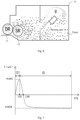
- FIG. 7 illustrates a curve showing the current signal of the detection unit changing with time in the state that the toner cartridge is not short of toner.
- 1 shown in FIG. 7 represents the time period corresponding to the initial stage of the image-forming apparatus executing the printing task
- (2) shown in FIG. 7 represents the time period between after the developing roller 11 rotates for a certain time (for example, 1.61 seconds shown in FIG. 7 ) and the time that the printing task is finished.
- the stirring unit 14 may rotate, friction may be generated between the detection unit 18 (such as the copper sheet) and the toner in the toner hopper 13, and the toner in the toner hopper 13 may capture the electrons in the copper sheet, causing the copper sheet to be charged with a small amount of positive charge which may be accumulated. Therefore, a forward current may be generated on the copper sheet, and the forward current may gradually increase.
- the time period (2) after the developing roller 11 rotates for a certain time, the undeveloped negatively charged toner on the developing roller 11 may return to the toner hopper 13, the toner near the developing roller 11 and the supply roller 12 may be more negatively charged.
- the stirring unit 14 When the stirring unit 14 rotates to the vicinity of the supply roller 12, the toner may conduct negative charges thereof to the copper sheet. At this point, negative charges may be accumulated on the copper sheet, so that the positive charges on the copper sheet may gradually decrease, and the negative charges may gradually increase; and the positive current outputted by the copper sheet may gradually decreases until the current becomes negative. Before the end of the printing task, if a certain amount of toner is in the toner hopper 13, the copper sheet may continuously output the negative current exceeding a certain value.
- the controller 2 may determine that current toner cartridge 1 is not short of toner.
- the controller 2 may determine that current toner cartridge 1 is not short of toner.
- the second threshold and the third threshold may be, for example, 0.002 ⁇ A, 0.0025 ⁇ A or the like.
- Case 2 in the process of executing the printing task by the image-forming apparatus, the toner hopper 13 changes from having a certain amount of toner (that is, the toner cartridge 1 is not short of toner) to being short of toner.
- the undeveloped negatively charged toner on the developing roller 11 may return to the toner hopper 13, and the toner near the developing roller 11 and the supply roller 12 may be more negatively charged.
- the stirring unit 14 rotates to the vicinity of the supply roller 12, the toner may conduct negative charges thereof to the copper sheet.
- negative charges may be accumulated on the copper sheet, so that the positive charges on the copper sheet may gradually decrease, and the negative charges may gradually increase, thereby generating a negative current to the current detection unit 3.
- the negatively charged toner in the vicinity of the supply roller 12 may be difficult to be in contact with the copper sheet.
- the negative charges on the copper sheet may gradually decrease until near zero, so that basically no charges flow on the copper sheet.
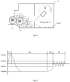
- FIG. 9 illustrates another schematic curve showing the current signal of the detection unit changing with time when the toner cartridge 1 changes from the state of no toner shortage to the state of toner shortage during the execution of the printing task.
- 1 shown in FIG. 9 represents the time period corresponding to the initial stage of the image-forming apparatus executing the printing task; (2) shown in FIG. 9 represents the time period between after the developing roller 11 rotates for a certain time (for example, 1.61 seconds shown in FIG. 7 ) and the time that the printing task is short of toner; and 3 shown in FIG. 9 represents the time period corresponding to the state of toner shortage of the toner cartridge 1.
- the stirring unit 14 may rotate, and friction may be generated between the detection unit 18 (such as the copper sheet) and the toner in the toner hopper 13, and the toner in the toner hopper 13 may capture the electrons in the copper sheet, causing the copper sheet to be charged with a small amount of positive charge which may be accumulated. Therefore, a forward current may be generated on the copper sheet and gradually increase.
- the time period (2) after the developing roller 11 rotates for a certain time, undeveloped negatively charged toner on the developing roller 11 may return to the toner hopper 13, the toner near the developing roller 11 and the supply roller 12 may be more negatively charged.
- the stirring unit 14 When the stirring unit 14 rotates to the vicinity of the supply roller 12, the toner may conduct negative charges thereof to the copper sheet. At this point, negative charges may be accumulated on the copper sheet, so that the positive charges on the copper sheet may gradually decrease, and the negative charges may gradually increase; and the positive current outputted by the copper sheet may gradually decrease until the current becomes negative. During the time period 3, the negative charges on the copper sheet may gradually decrease until near zero; and at this point, basically, no charges flow on the copper sheet.
- the controller 2 may determine that the toner cartridge 1 is short of toner.
- the first threshold may be, for example, 0.001 ⁇ A, 0.0015 ⁇ A or the like; and the first preset time may be, for example, 3 seconds, 4 seconds or the like.
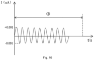
- FIG. 10 illustrates another schematic curve showing the current signal of the detection unit 18 changing with time in the state that the toner cartridge is always short of toner.
- FIG. 10 represents the time period corresponding to the state that the toner cartridge 1 is short of toner.
- the change range of the current signal of the detection unit may be significantly small, and the current may be near 0.
- the controller 2 may determine that the toner cartridge 1 is short of toner.
- the first threshold may be, for example, 0.001 ⁇ A, 0.0015 ⁇ A or the like; and the first preset time may be, for example, 3 seconds, 3 seconds, 4 seconds or the like.
- the current detection unit may be disposed to detect the current signal of the detection unit which is disposed on the stirring unit and follows the rotation of the stirring unit, thereby determining whether the toner cartridge has toner or is short of toner according to the current detection result, which may have high detection accuracy and convenience.
- the current detection unit may be disposed to detect the current signal of the detection unit which is disposed on the stirring unit and follows the rotation of the stirring unit, thereby determining whether the toner cartridge has toner or is short of toner according to the current detection result, which may have high detection accuracy and convenience.
- relatively large amount of toner may be still on the developing roller and supply roller, which may ensure that white streaks phenomenon may not occur within a certain number of pages.
- the toner cartridge may determine whether the toner cartridge has toner or is short of toner before the toner in the toner cartridge is almost used up but there is no image defect, which may be convenient to remind the user to add toner or replace the toner cartridge in advance when printing errors (such as white streaks phenomenon) occur.
- embodiments of the present disclosure also provide an image-forming apparatus.
- the image-forming apparatus may be disposed with the toner cartridge 1, where the stirring unit 14 may be disposed in the toner cartridge 1; and the image-forming apparatus or the toner cartridge 1 may also include the current detection unit 3.
- the controller 2 may be configured to control the rotation of the stirring unit 14 and drive the detection unit 18 to rotate.
- the current detection unit 3 may be electrically connected to the detection unit 18 and the controller 2 and configured to detect the current signal of the detection unit 18 and output the current detection result to the controller 2; and the controller 2 may also be configured to determine whether the toner cartridge 1 is short of toner according to the current detection result.
- the detection unit 18 may be a conductive material, such as a copper sheet.
- the detection unit 18 may be attached to the stirring frame blade 142, which may be in desirable contact with the toner, thereby achieving desirable toner sensitivity.
- the detection unit 18 may also be a metal sheet having same or similar chemical properties as copper, for example, iron, aluminum or the like; or the detection unit 18 may also be an alloy which is made of copper combined with other metals, stainless steel or the like, which may not be limited according to embodiments of the present disclosure.
- the stirring frame blade 142 of the stirring unit 14 itself may also be a conductive material; or a conductive coating may be on the surface of the stirring frame blade, which may be used as the electrical connection between the detection unit 18 and the current detection unit.
- the current detection unit 3 may detect the current signal of the detection unit 18; and if it is detected that the absolute value of the current signal of the detection unit 18 is less than or equal to the first threshold for a duration exceeding the first preset time, or detected average current value of the detection unit 18 within the first preset time is less than or equal to the first threshold, it may determine the toner cartridge 1 is short of toner.
- the stirring unit 14 may determine that the toner cartridge 1 is not short of toner.
- the first process may be that the current signal of the detection unit 18 may be a gradually increasing positive current at first and may then gradually decrease to a negative current that absolute value of the negative current is greater than or equal to the second threshold.
- the current detection unit may be disposed to detect the current signal of the detection unit which is disposed on the stirring unit and follows the rotation of the stirring unit, thereby determining whether the toner cartridge has toner or is short of toner, which may have high detection accuracy and convenience.
- the toner cartridge is short of toner, relatively large amount of toner may be still on the developing roller and supply roller, which may ensure that toner shortage may not occur to case abnormal images within a certain number of pages. Therefore, it may determine whether the toner cartridge has toner or is short of toner before the toner in the toner cartridge is almost used up but there is no image defect, which may be convenient to remind the user to add toner or replace the toner cartridge in advance.
Landscapes
- Physics & Mathematics (AREA)
- General Physics & Mathematics (AREA)
- Dry Development In Electrophotography (AREA)
- Control Or Security For Electrophotography (AREA)
Abstract
Description
- This application is based on the Chinese Application named " TONER CARTRIDGE, METHOD FOR DETECTING REMAINING TONER AMOUNT, AND IMAGE-FORMING APPARATUS ", which claims priority to
Chinese Application No. 202010888189.8, filed August 28, 2020 - The present disclosure generally relates to the field of image-forming technology and, more particularly, relates to a toner cartridge, a method for detecting a remaining toner amount, and an image-forming apparatus.
- Image-forming apparatuses are indispensable office equipment in daily use. Toner is a required material for laser printers to complete smooth printing.
- In existing image-forming apparatus, toner is normally placed in the toner cartridge of the image-forming apparatus, and the user needs to remove the toner cartridge from the printer to check the remaining toner amount, which is inconvenient for the user. Moreover, when performing printing through the image-forming apparatus, the user often encounters the situation that the printing is paused due to insufficient toner and may only temporarily find the toner for adding, which may waste the user's time and even delay the user's printing progress to cause huge loss.
- In particular, existing detection solutions of the toner in the toner cartridge may include optical toner detection, capacitive toner detection, and ultrasonic toner detection, which may be relatively expensive or have complex structures. Furthermore, another toner detection type, for example, magnetic signal toner detection, may be only suitable for magnetic toner detection. In addition, insufficient toner may be detected by measuring the SR (supply roller) current, but the disadvantage of such solution is that when the toner is detected to be insufficient, the images may already have defects, and the user may not be reminded in advance.
- Embodiments of the present application provide a toner cartridge, a method for detecting a remaining toner amount, and an image-forming apparatus, which determine whether the toner cartridge has toner or is short of toner before the images have defects, and the detection process is relatively convenient with low detection cost.
- The first aspect of the present disclosure provides a toner cartridge. The toner cartridge is installed on an image-forming apparatus. The toner cartridge includes a toner hopper, configured to hold toner; a stirring unit, disposed in the toner hopper and configured to stir the toner in the toner hopper; and a detection unit, disposed on the stirring unit and configured to be in contact with the toner during a process of stirring the toner by the stirring unit and output a current signal. A housing of the toner cartridge is disposed with electrical connection contacts, and the detection unit is electrically connected to the image-forming apparatus through the electrical connection contacts.
- Combined with the first aspect, in one possible implementation, the image-forming apparatus includes a controller; the image-forming apparatus or the toner cartridge includes a current detection unit; and the current detection unit is electrically connected with the detection unit and the controller; and the current detection unit detects the current signal outputted by the detection unit and output a current detection result to the controller, such that the controller determines whether the toner cartridge is short of toner according to the current detection result.
- Combined with the first aspect, in one possible implementation, the stirring unit includes a stirring frame and a stirring frame blade which is disposed on a peripheral surface of the stirring frame; and the detection unit is disposed on the stirring frame blade.
- Combined with the first aspect, in one possible implementation, the detection unit is made of a conductive material and attached to the stirring frame blade; or the stirring frame blade itself is made of a conductive material.
- The second aspect of the present disclosure provides a method for detecting a remaining toner amount, applied to a toner cartridge. The toner cartridge is installed on an image-forming apparatus; a stirring unit is disposed in the toner cartridge; the image-forming apparatus or the toner cartridge includes a current detection unit; the image-forming apparatus includes a controller; a detection unit is disposed on the stirring unit and configured to be in contact with toner during a process of stirring the toner by the stirring unit and output a current signal; and the current detection unit is electrically connected to the detection unit and the controller. The method includes rotating the stirring unit to drive the detection unit to rotate, where the detection unit is in contact with the toner in the toner cartridge to generate the current signal, such that the current detection unit detects the current signal of the detection unit and outputs a current detection result to the controller; and the controller determines whether the toner cartridge is short of toner according to the current detection result.
- Combined with the second aspect, in one possible implementation, the stirring unit includes a stirring frame and a stirring frame blade which is disposed on a peripheral surface of the stirring frame; and the detection unit is disposed on the stirring frame blade.
- Combined with the second aspect, in one possible implementation, the detection unit is made of a conductive material and attached to the stirring frame blade; or the stirring frame blade itself is made of a conductive material.
- The third aspect of the present disclosure provides an image-forming apparatus. The image-forming apparatus includes a toner cartridge installed on the image-forming apparatus, where a stirring unit is disposed in the toner cartridge; and a detection unit is disposed on the stirring unit and configured to be in contact with toner during a process of stirring the toner by the stirring unit and output a current signal; a controller, configured to control the stirring unit to rotate and drive the detection unit to rotate when the image forming device executes a printing task; and a current detection unit, electrically connected to the detection unit and the controller and configured to detect the current signal of the detection unit and output a current detection result to the controller, where the controller determines whether the toner cartridge is short of toner according to the current detection result.
- Combined with the third aspect, in one possible implementation, wherein the controller is configured to: during a rotating process of the stirring unit, if the current detection unit detects that an absolute value of a current signal of the detection unit is less than or equal to a first threshold for a duration exceeding a first preset time, determine that the toner cartridge is short of toner.
- Combined with the third aspect, in one possible implementation, wherein the controller is configured to: during a rotating process of the stirring unit, if the current detection unit detects that a change process of a current of the detection unit is a first process, determine that the toner cartridge is not short of toner, wherein: the first process is that the current of the detection unit changes from a gradually increasing positive current to a gradually decreasing negative current wherein an absolute value of the negative current is greater than or equal to a second threshold.
- The fourth aspect of the present disclosure provides a method for detecting a remaining toner amount, applied to an image-forming apparatus. A toner cartridge is installed on the image-forming apparatus; a stirring unit is disposed in the toner cartridge; the image-forming apparatus includes a controller; the image-forming apparatus or the toner cartridge includes a current detection unit; a detection unit is disposed on the stirring unit and configured to be in contact with toner during a process of stirring the toner by the stirring unit and output a current signal; and the current detection unit is electrically connected to the detection unit and the controller. The method includes when the image forming device executes a printing task, controlling, by the controller, the stirring unit to rotate and drive the detection unit to rotate; detecting, by the current detection unit, the current signal of the detection unit and outputting a current detection result to the controller; and determining, by the controller, whether the toner cartridge is short of toner according to the current detection result.
- Combined with the fourth aspect, in one possible implementation, wherein determining, by the controller, whether the toner cartridge is short of toner according to the current detection result includes: during a rotating process of the stirring unit, if the current detection unit detects that an absolute value of a current of the detection unit is less than or equal to a first threshold for a duration exceeding a first preset time, determining, by the controller, that the toner cartridge is short of toner.
- Combined with the fourth aspect, in one possible implementation, wherein determining, by the controller, whether the toner cartridge is short of toner according to the current detection result includes: during a rotating process of the stirring unit, if the current detection unit detects that a change process of a current of the detection unit is a first process, determining, by the controller, that the toner cartridge is not short of toner, wherein: the first process is that the current of the detection unit changes from a gradually increasing positive current to a gradually decreasing negative current wherein an absolute value of the negative current is greater than or equal to a second threshold.
- It can be understood that in embodiments of the present disclosure, the current detection unit may be disposed to detect the current of the detection unit which is disposed on the stirring unit and follows the rotation of the stirring unit, thereby determining whether the toner cartridge has toner or is short of toner according to the current detection result, which may have high detection accuracy and convenience, and have no need to manually open the toner cartridge to check. In addition, at this point, if it determines that the toner cartridge is short of toner, relatively large amount of toner may be still on the developing roller and supply roller, which may ensure that white streaks phenomenon may not occur within a certain number of pages. Therefore, it may determine whether the toner cartridge has toner or is short of toner before the toner in the toner cartridge is almost used up but there is no image defect, which may be convenient to remind the user to add toner or replace the toner cartridge in advance.
- To clearly describe the technical solutions of various embodiments of the present disclosure, the drawings which need to be used for describing various embodiments are described below. Obviously, the drawings in the following description are merely some embodiments of the present disclosure. For those skilled in the art, other drawings may be obtained in accordance with the drawings without creative efforts.
-
FIG. 1 illustrates a structural schematic of a toner cartridge provided by exemplary embodiments of the present disclosure. -
FIG. 2 illustrates a connection relationship schematic between a current detection unit and a detection unit provided by exemplary embodiments of the present disclosure. -
FIG. 3 illustrates a structural schematic of a stirring unit provided by exemplary embodiments of the present disclosure. -
FIG. 4 illustrates a flowchart of a method for detecting a toner remaining amount provided by exemplary embodiments of the present disclosure. -
FIG. 5 illustrates another structural schematic of a toner cartridge provided by exemplary embodiments of the present disclosure. -
FIG. 6 illustrates another structural schematic of a toner cartridge provided by exemplary embodiments of the present disclosure. -
FIG. 7 illustrates a curve showing a current signal of a detection unit changing with time provided by exemplary embodiments of the present disclosure. -
FIG. 8 illustrates another structural schematic of a toner cartridge provided by exemplary embodiments of the present disclosure. -
FIG. 9 illustrates another curve showing a current signal of a detection unit changing with time provided by exemplary embodiments of the present disclosure. -
FIG. 10 illustrates another curve showing a current signal of a detection unit changing with time provided by exemplary embodiments of the present disclosure. - To better understand technical solutions of the present disclosure, embodiments of the present disclosure are described in detail with reference to accompanying drawings.
- It should be noted that described embodiments are only a part of embodiments of the present disclosure, rather than all embodiments. Based on embodiments of the present disclosure, all other embodiments obtained by those skilled in the art without creative work shall fall within the protection scope of the present disclosure.
- In the present disclosure, "at least one" indicates one or more, and "a plurality of" indicates two or more. "And/or" describes the association relationship of associated objects, indicating that there can be three types of relationships. For example, A and/or B indicates that A exists alone, A and B exist at the same time, and B exists alone, where A and B may be singular or plural. The character "/" normally indicates that the contextual objects are an "or" relationship. "At least one of the following" or similar expressions indicate any combination of these items, including any combination of single or plural items. For example, at least one of a, b, or c may indicate that a, b, c, a-b, a-c, b-c or a-b-c, where a, b, c are singular or plural.
- The image-forming apparatus is configured to perform image-forming jobs such as generating, printing, receiving and transmitting image data; and examples of the image-forming apparatus may include a printer, a scanner, a copier, a facsimile, and a MultiFunctional Peripheral (MFP) that performs above functions in a single device.
- The image-forming apparatus may include a controller and an image-forming part. The controller may control the image data to be obtained by the image-forming part to form images on conveyed paper.
- In some embodiments, the image-forming part may include an exposing assembly, a photosensitive drum (OPC, organic photoconductor), a charging roller, a developing roller, an intermediate transfer belt, a primary transfer roller, a secondary transfer roller, a fixing unit, a cleaning blade, and the like.
- The image-forming process of the image-forming part may include charging the surface of the organic photoconductor by the charging roller, generating an exposure signal according to the image data by the exposing assembly, emitting a laser beam corresponding to the exposure signal, and exposing the surface of the organic photoconductor, thereby forming an electrostatic latent image on the surface of the organic photoconductor. Next, the developing roller develops the electrostatic latent image on the surface of the organic photoconductor into a toner image. Then, the primary transfer roller transfers the toner image on the surface of the organic photoconductor to the surface of the intermediate transfer belt for the first transfer, thereby forming the toner image on the surface of the intermediate transfer belt. The secondary transfer roller transfers the toner image on the surface of the intermediate transfer belt to paper for the second transfer. The paper on which the toner image is secondarily transferred is conveyed into a fixing unit. The fixing unit fixes the toner image on the paper to be discharged. In addition, the toner remaining on the surface of the organic photoconductor is removed by the cleaning blade.
- If the image-forming apparatus has a color printing function, the number of the above-mentioned exposing assemblies, organic photoconductors, charging rollers, developing rollers and the like may be 4 or more.
- The description of the toner cartridge in the present disclosure is described hereinafter.
-
FIG. 1 illustrates a structural schematic of a toner cartridge provided by exemplary embodiments of the present disclosure. - A
toner cartridge 1 may be an integrated toner cartridge or a split toner cartridge. The integrated toner cartridge may integrate thetoner cartridge 1 and the organic photoconductor on a same apparatus. When the toner is used up or the organic photoconductor is damaged, the toner cartridge and the organic photoconductor may be replaced together. For the split toner cartridge, the organic photoconductor and toner cartridge may be separated to be not attached. When the toner is used up, it may only need to replace old toner cartridge with new toner cartridge; and as long as the lifespan of the toner cartridge has not reached, the split toner cartridge may continue to use. Atoner cartridge 1 may be an integrated toner cartridge or a split toner cartridge. - As shown in
FIG. 1 , in embodiments of the present disclosure, thetoner cartridge 1 may include a developing roller (DR) 11, a supply roller (SR) 12, atoner hopper 13 and a stirringunit 14 disposed in thetoner hopper 13. - If the integrated toner cartridge is used, the
toner cartridge 1 may also include anorganic photoconductor 15, a chargingroller 16, and the like. - The
toner hopper 13 may be configured to store the toner for developing. Thetoner hopper 13 may have a toner output outlet for outputting toner. The stirringunit 14 may be configured to stir the toner in thetoner hopper 13. The toner in thetoner hopper 13 may be outputted to thesupply roller 12 through the toner output outlet by stirring. Thesupply roller 12 may be disposed at the toner output outlet and configured to transfer the toner outputted from the toner output outlet to the developingroller 11. When the developingroller 11 is applied with a developing bias voltage, the toner near the developingroller 11 may adhere to the region of theorganic photoconductor 15 exposed by the exposing assembly, thereby developing the electrostatic latent image on the surface of theorganic photoconductor 15 into the toner image. - In embodiments of the present disclosure, the
toner cartridge 1 may further include structures such as acleaning blade 17. Thecleaning blade 17 may be disposed on the main body of the image-forming apparatus or in thetoner cartridge 1. -
FIG. 2 illustrates a connection relationship schematic between a current detection unit and a detection unit provided by exemplary embodiments of the present disclosure. - To solve the problems in existing technology, in embodiments of the present disclosure, the stirring
unit 14 may be disposed with adetection unit 18. Thedetection unit 18 may be disposed on the stirringunit 14 and configured to be in contact with the toner during the process of stirring the toner by the stirringunit 14 and output a current signal. - The image-forming apparatus may include the controller; the image-forming apparatus or the
toner cartridge 1 may include acurrent detection unit 3; and thecurrent detection unit 3 may be electrically connected with thedetection unit 18 and thecontroller 2. Thecurrent detection unit 3 may detect the current signal outputted by thedetection unit 18 and output the current detection result to thecontroller 2, such that thecontroller 2 may determine whether thetoner cartridge 1 is short of toner according to the current detection result. The housing of thetoner cartridge 1 may be disposed with electrical connection contacts, and thedetection unit 18 may be electrically connected with the image-forming apparatus through the electrical connection contacts. -
FIG. 3 illustrates a structural schematic of a stirring unit provided by exemplary embodiments of the present disclosure. - As shown in
FIG. 3 , as an implementation manner, the stirringunit 14 may include a stirringframe 141 and a stirringframe blade 142 disposed on the peripheral surface of the stirringframe 141. The stirringunit 14 may further include a stirringshaft 143, and the stirringshaft 143 may drive the stirringframe 141 to rotate, thereby driving the stirringframe blade 142 to rotate. It can be understood that the stirringframe blade 142 may be configured to have desirable stirring intensity to improve stirring quality. - The
detection unit 18 may be configured to be in contact (e.g., having friction) with the toner to generate the current signal. - As an implementation manner, the
detection unit 18 may be a conductive material, such as a copper sheet. Thedetection unit 18 may be attached to the stirringframe blade 142, which may be in desirable contact with the toner, thereby achieving desirable toner sensitivity. In other implementation manners, thedetection unit 18 may also be a metal sheet having same or similar chemical properties as copper, for example, iron, aluminum or the like; or thedetection unit 18 may also be an alloy which is made of copper combined with other metals, stainless steel or the like, which may not be limited according to embodiments of the present disclosure. - As an implementation manner, the stirring
frame blade 142 of the stirringunit 14 itself may also be a conductive material; or a conductive coating may be on the surface of the stirring frame blade, which may be used as the electrical connection between thedetection unit 18 and the current detection unit. - When the remaining toner amount needs to be detected, the
controller 2 may control the stirringunit 14 to rotate under the driving source (not shown in drawings), for example, control the rotation of the stirringshaft 143 to drive the stirringframe 141 and the stirringframe blade 142. The stirringunit 14 may rotate along the W direction (clockwise) shown inFIG. 1 . - Embodiments of the present disclosure provide a method for detecting the remaining toner amount. The method may be applied to the
toner cartridge 1 and include following exemplary steps. - For example, the stirring unit may rotate to drive the detection unit to rotate; and the detection unit may be in contact with the toner in the toner cartridge to generate the current signal, such that the current detection unit may detect the current signal of the detection unit and output the current detection result to the controller, and the controller may determine whether the toner cartridge is short of toner according to the current detection result.
- It can be understood that in embodiments of the present disclosure, the current detection unit may be disposed to detect the current signal of the detection unit which is disposed on the stirring unit and follows the rotation of the stirring unit, thereby determining whether the toner cartridge has toner or is short of toner according to the current detection result, which may have high detection accuracy and convenience, and have no need to manually open the toner cartridge to check. In addition, at this point, if it determines that the toner cartridge is short of toner, relatively large amount of toner may be still on the developing roller and supply roller, which may ensure that white streaks phenomenon may not occur within a certain number of pages. Therefore, it may determine whether the toner cartridge has toner or is short of toner before the toner in the toner cartridge is almost used up but there is no image defect, which may be convenient to remind the user to add toner or replace the toner cartridge in advance when printing errors (such as white streak phenomenon) occur.
-
FIG. 4 illustrates a flowchart of a method for detecting the toner remaining amount provided by exemplary embodiments of the present disclosure. - As shown in
FIG. 4 , the method for detecting the remaining toner amount provided by the present disclosure, applied to the image-forming apparatus, may include following exemplary steps. - At S201, the controller may control the stirring unit to rotate and drive the detection unit to rotate.
- At S202, the current detection unit may detect the current signal of the detection unit and output the current detection result to the controller.
- At S203, the controller may determine whether the toner cartridge is short of toner according to the current detection result.
- Triggering the controller to detect the toner amount may be, but may not be limited, to any one or more of following cases: 1) The
toner cartridge 1 is installed on the image-forming apparatus; 2) the image-forming apparatus is powered on or turned on; 3) before or after the print job is executed; 4) during the execution of the print task; and 5) receiving an instruction from the user to detect the remaining toner amount. Thecontroller 2 of the image-forming apparatus may realize the detection of the remaining toner amount by rotating the stirring unit and driving the detecting unit to rotate. - As an implementation manner, if the
toner cartridge 1 is short of toner, thecontroller 2 may prompt the user that current image-forming apparatus is in a state of lack of toner through the display unit (such as a display screen) and/or sound output unit (such as a speaker) of the image-forming apparatus, thereby reminding the user to add toner or replace the toner cartridge. - The current detection result outputted by the
current detection unit 3 may be, for example, the current value of thedetection unit 18. For example, thecurrent detection unit 3 may be an nA (10-9A) or even a pA (10-12A) level current detection element with ultra-high sensitivity. In other implementation manners, thecurrent detection unit 3 may also be disposed on thetoner cartridge 1 or inside thecontroller 2. - As an implementation manner, the
controller 2 may determine whether thetoner cartridge 1 is short of toner according to the current detection result, which may include that during the rotation of the stirringunit 14, thecurrent detection unit 3 may detect the current signal of thedetection unit 18; and if it is detected that the absolute value of the current signal of thedetection unit 18 is less than or equal to the first threshold for a duration exceeding the first preset time, or detected average current value of thedetection unit 18 within the first preset time is less than or equal to the first threshold, it may determine thetoner cartridge 1 is short of toner. - As an implementation manner, the
controller 2 may determine whether thetoner cartridge 1 is short of toner according to the current detection result, which may include that after the stirringunit 14 starts to rotate, if the change process of the current signal of thedetection unit 18 is the first process, it may determine that thetoner cartridge 1 is not short of toner, where the first process may be that the current signal of thedetection unit 18 may be a gradually increasing positive current at first and may then gradually decrease to a negative current that absolute value of the negative current is greater than or equal to the second threshold. - As an implementation manner, the
controller 2 may determine whether thetoner cartridge 1 is short of toner according to the current detection result, which may include that during the rotation of the stirringunit 14, thecurrent detection unit 3 may detect the current signal of thedetection unit 18; and if it is detected that the absolute value of the current signal of thedetection unit 18 is greater than or equal to the third threshold, it may determine that thetoner cartridge 1 is not short of toner. - As an implementation manner, the
controller 2 may also determine the remaining toner amount or the range of the remaining toner amount according to the current detected by thecurrent detection unit 3. For example, when at a certain moment, the absolute value of the current signal of thedetection unit 18 exceeds a certain preset value, it may indicate that the remaining toner amount is relatively large, for example, at least 70%. - The implementation principle of the present disclosure is described below by taking the detection of the remaining toner amount in the process of executing the printing task by the image-forming apparatus as an example.
- Case 1: during the printing process of the image-forming apparatus, a certain amount of toner is in the
toner hopper 13 continuously (that is, thetoner cartridge 1 is not short of toner). - As shown in
FIG. 5 , at the initial stage of the image-forming apparatus executing the printing task, if a certain amount of toner is in thetoner hopper 13, during the rotation of the stirringunit 14, friction may be generated between the detection unit 18 (a copper sheet is used as an example for illustration below) and the toner in thetoner hopper 13, and the toner in thetoner hopper 13 may easily capture the electrons in the copper sheet, so that the copper sheet may be charged with a small amount of positive charges which may be accumulated, thereby generating a forward current to thecurrent detection unit 3. - As shown in
FIG. 6 , after the developingroller 11 rotates for a certain time, the undeveloped negatively charged toner on the developingroller 11 may return to thetoner hopper 13, and the toner near the developingroller 11 and thesupply roller 12 may be more negatively charged. When the stirringunit 14 rotates to the vicinity of thesupply roller 12, the toner may conduct negative charges thereof to the copper sheet. At this point, negative charges may be accumulated on the copper sheet, so that the positive charges on the copper sheet may gradually decrease, and the negative charges may gradually increase, thereby generating a negative current to thecurrent detection unit 3. Before the end of the printing task, if a certain amount of toner is in thetoner hopper 13, the copper sheet may continuously output a negative current exceeding a certain value. -
FIG. 7 illustrates a curve showing the current signal of the detection unit changing with time in the state that the toner cartridge is not short of toner. - For
case FIG. 7 represents the time period corresponding to the initial stage of the image-forming apparatus executing the printing task, and (2) shown inFIG. 7 represents the time period between after the developingroller 11 rotates for a certain time (for example, 1.61 seconds shown inFIG. 7 ) and the time that the printing task is finished. - As shown in
FIG. 7 , during thetime period ①, the stirringunit 14 may rotate, friction may be generated between the detection unit 18 (such as the copper sheet) and the toner in thetoner hopper 13, and the toner in thetoner hopper 13 may capture the electrons in the copper sheet, causing the copper sheet to be charged with a small amount of positive charge which may be accumulated. Therefore, a forward current may be generated on the copper sheet, and the forward current may gradually increase. During the time period (2), after the developingroller 11 rotates for a certain time, the undeveloped negatively charged toner on the developingroller 11 may return to thetoner hopper 13, the toner near the developingroller 11 and thesupply roller 12 may be more negatively charged. When the stirringunit 14 rotates to the vicinity of thesupply roller 12, the toner may conduct negative charges thereof to the copper sheet. At this point, negative charges may be accumulated on the copper sheet, so that the positive charges on the copper sheet may gradually decrease, and the negative charges may gradually increase; and the positive current outputted by the copper sheet may gradually decreases until the current becomes negative. Before the end of the printing task, if a certain amount of toner is in thetoner hopper 13, the copper sheet may continuously output the negative current exceeding a certain value. - As disclosed above, after the stirring
unit 14 starts to rotate, if thecurrent detection unit 3 detects that the current signal of thedetection unit 18 has a change process of "the current signal of thedetection unit 18 may be a gradually increasing positive current at first and may then gradually decrease to a negative current that absolute value of the negative current is greater than or equal to the second threshold", thecontroller 2 may determine thatcurrent toner cartridge 1 is not short of toner. Or during the rotation of the stirringunit 14, if thecurrent detection unit 3 detects that the absolute value of the current signal of thedetection unit 18 is greater than or equal to the third threshold, thecontroller 2 may determine thatcurrent toner cartridge 1 is not short of toner. The second threshold and the third threshold may be, for example, 0.002 µA, 0.0025 µA or the like. - Case 2: in the process of executing the printing task by the image-forming apparatus, the
toner hopper 13 changes from having a certain amount of toner (that is, thetoner cartridge 1 is not short of toner) to being short of toner. - As shown in
FIG. 5 , at the initial stage of the image-forming apparatus executing the printing task, if a certain amount of toner is in thetoner hopper 13, during the rotation of the stirringunit 14, friction may be generated between the copper sheet and the toner in thetoner hopper 13, and the toner in thetoner hopper 13 may easily capture the electrons in the copper sheet, so that the copper sheet may be charged with a small amount of positive charges which may be accumulated, thereby generating a forward current to thecurrent detection unit 3. - As shown in
FIG. 6 , after the developingroller 11 rotates for a certain time, the undeveloped negatively charged toner on the developingroller 11 may return to thetoner hopper 13, and the toner near the developingroller 11 and thesupply roller 12 may be more negatively charged. When the stirringunit 14 rotates to the vicinity of thesupply roller 12, the toner may conduct negative charges thereof to the copper sheet. At this point, negative charges may be accumulated on the copper sheet, so that the positive charges on the copper sheet may gradually decrease, and the negative charges may gradually increase, thereby generating a negative current to thecurrent detection unit 3. - As shown in
FIG. 8 , if the toner in thetoner hopper 13 is gradually consumed until the toner cartridge is short of toner before the end of the printing task, the negatively charged toner in the vicinity of thesupply roller 12 may be difficult to be in contact with the copper sheet. At this point, the negative charges on the copper sheet may gradually decrease until near zero, so that basically no charges flow on the copper sheet. -
FIG. 9 illustrates another schematic curve showing the current signal of the detection unit changing with time when thetoner cartridge 1 changes from the state of no toner shortage to the state of toner shortage during the execution of the printing task. - For
case FIG. 9 represents the time period corresponding to the initial stage of the image-forming apparatus executing the printing task; (2) shown inFIG. 9 represents the time period between after the developingroller 11 rotates for a certain time (for example, 1.61 seconds shown inFIG. 7 ) and the time that the printing task is short of toner; and ③ shown inFIG. 9 represents the time period corresponding to the state of toner shortage of thetoner cartridge 1. - As shown in
FIG. 9 , during thetime period ①, the stirringunit 14 may rotate, and friction may be generated between the detection unit 18 (such as the copper sheet) and the toner in thetoner hopper 13, and the toner in thetoner hopper 13 may capture the electrons in the copper sheet, causing the copper sheet to be charged with a small amount of positive charge which may be accumulated. Therefore, a forward current may be generated on the copper sheet and gradually increase. During the time period (2), after the developingroller 11 rotates for a certain time, undeveloped negatively charged toner on the developingroller 11 may return to thetoner hopper 13, the toner near the developingroller 11 and thesupply roller 12 may be more negatively charged. When the stirringunit 14 rotates to the vicinity of thesupply roller 12, the toner may conduct negative charges thereof to the copper sheet. At this point, negative charges may be accumulated on the copper sheet, so that the positive charges on the copper sheet may gradually decrease, and the negative charges may gradually increase; and the positive current outputted by the copper sheet may gradually decrease until the current becomes negative. During thetime period ③, the negative charges on the copper sheet may gradually decrease until near zero; and at this point, basically, no charges flow on the copper sheet. - As disclosed above, during the rotation of the stirring
unit 14, if it is detected that the absolute value of the current signal of thedetection unit 18 is less than or equal to the first threshold and the duration exceeds the first preset time, thecontroller 2 may determine that thetoner cartridge 1 is short of toner. The first threshold may be, for example, 0.001 µA, 0.0015 µA or the like; and the first preset time may be, for example, 3 seconds, 4 seconds or the like. - Case 3: before the image-forming apparatus executes the printing task, the
toner hopper 13 is already short of toner. - As shown in
FIG. 8 , if thetoner hopper 13 is already short of toner before the printing task is executed, during the rotation of the stirringunit 14, no friction may be generated between the copper sheet and the toner in thetoner hopper 13. At this point, basically, no charges flow on the copper sheet, so that the copper sheet may hardly generate current. -
FIG. 10 illustrates another schematic curve showing the current signal of thedetection unit 18 changing with time in the state that the toner cartridge is always short of toner. - ③ shown in
FIG. 10 represents the time period corresponding to the state that thetoner cartridge 1 is short of toner. - As shown in
FIG. 10 , in the state that the toner cartridge is always short of toner, the change range of the current signal of the detection unit may be significantly small, and the current may be near 0. - As disclosed above, during the rotation of the stirring
unit 14, if it is detected that the absolute value of the current signal of thedetection unit 18 is less than or equal to the first threshold and the duration exceeds the first preset time, thecontroller 2 may determine that thetoner cartridge 1 is short of toner. The first threshold may be, for example, 0.001 µA, 0.0015 µA or the like; and the first preset time may be, for example, 3 seconds, 3 seconds, 4 seconds or the like. - It can be understood that in embodiments of the present disclosure, the current detection unit may be disposed to detect the current signal of the detection unit which is disposed on the stirring unit and follows the rotation of the stirring unit, thereby determining whether the toner cartridge has toner or is short of toner according to the current detection result, which may have high detection accuracy and convenience. In addition, at this point, if it determines that the toner cartridge is short of toner, relatively large amount of toner may be still on the developing roller and supply roller, which may ensure that white streaks phenomenon may not occur within a certain number of pages. Therefore, it may determine whether the toner cartridge has toner or is short of toner before the toner in the toner cartridge is almost used up but there is no image defect, which may be convenient to remind the user to add toner or replace the toner cartridge in advance when printing errors (such as white streaks phenomenon) occur.
- Referring to
FIGS. 1-3 , embodiments of the present disclosure also provide an image-forming apparatus. The image-forming apparatus may be disposed with thetoner cartridge 1, where the stirringunit 14 may be disposed in thetoner cartridge 1; and the image-forming apparatus or thetoner cartridge 1 may also include thecurrent detection unit 3. - The
controller 2 may be configured to control the rotation of the stirringunit 14 and drive thedetection unit 18 to rotate. - The
current detection unit 3 may be electrically connected to thedetection unit 18 and thecontroller 2 and configured to detect the current signal of thedetection unit 18 and output the current detection result to thecontroller 2; and thecontroller 2 may also be configured to determine whether thetoner cartridge 1 is short of toner according to the current detection result. - As an implementation manner, the
detection unit 18 may be a conductive material, such as a copper sheet. Thedetection unit 18 may be attached to the stirringframe blade 142, which may be in desirable contact with the toner, thereby achieving desirable toner sensitivity. In other implementation manners, thedetection unit 18 may also be a metal sheet having same or similar chemical properties as copper, for example, iron, aluminum or the like; or thedetection unit 18 may also be an alloy which is made of copper combined with other metals, stainless steel or the like, which may not be limited according to embodiments of the present disclosure. - As an implementation manner, the stirring
frame blade 142 of the stirringunit 14 itself may also be a conductive material; or a conductive coating may be on the surface of the stirring frame blade, which may be used as the electrical connection between thedetection unit 18 and the current detection unit. - As an implementation manner, during the rotation of the stirring
unit 14, thecurrent detection unit 3 may detect the current signal of thedetection unit 18; and if it is detected that the absolute value of the current signal of thedetection unit 18 is less than or equal to the first threshold for a duration exceeding the first preset time, or detected average current value of thedetection unit 18 within the first preset time is less than or equal to the first threshold, it may determine thetoner cartridge 1 is short of toner. - In an optional implementation manner, after the stirring
unit 14 starts to rotate, if the change process of the current signal of thedetection unit 18 is the first process, it may determine that thetoner cartridge 1 is not short of toner. - The first process may be that the current signal of the
detection unit 18 may be a gradually increasing positive current at first and may then gradually decrease to a negative current that absolute value of the negative current is greater than or equal to the second threshold. - Those skilled in the art can clearly understand that for the convenience and conciseness of description, the working process and principle of the
toner cartridge 1 and the image-forming apparatus described above may refer to corresponding description in above-mentioned method embodiments of the method for detecting the remaining toner amount, which may not be described in detail herein. - From above-mentioned embodiments, it may be seen that the solutions provided by the present disclosure may achieve at least following beneficial effects.
- It can be understood that in embodiments of the present disclosure, the current detection unit may be disposed to detect the current signal of the detection unit which is disposed on the stirring unit and follows the rotation of the stirring unit, thereby determining whether the toner cartridge has toner or is short of toner, which may have high detection accuracy and convenience. In addition, at this point, if it determines that the toner cartridge is short of toner, relatively large amount of toner may be still on the developing roller and supply roller, which may ensure that toner shortage may not occur to case abnormal images within a certain number of pages. Therefore, it may determine whether the toner cartridge has toner or is short of toner before the toner in the toner cartridge is almost used up but there is no image defect, which may be convenient to remind the user to add toner or replace the toner cartridge in advance.
- The above may merely be embodiments of the present disclosure. Changes or substitutions which may be easily thought by those skilled in the art within the technical scope disclosed by the present disclosure should be covered by the protection scope of the present disclosure. The protection scope of the present disclosure shall be subject to the protection scope of the claims.
Claims (13)
- A toner cartridge, installed on an image-forming apparatus, comprising:a toner hopper, configured to hold toner;a stirring unit, disposed in the toner hopper and configured to stir the toner in the toner hopper; anda detection unit, disposed on the stirring unit and configured to be in contact with the toner during a process of stirring the toner by the stirring unit and output a current signal, wherein:
a housing of the toner cartridge is disposed with electrical connection contacts, and the detection unit is electrically connected to the image-forming apparatus through the electrical connection contacts. - The toner cartridge according to claim 1, wherein:
the image-forming apparatus includes a controller; the image-forming apparatus or the toner cartridge includes a current detection unit; and the current detection unit is electrically connected with the detection unit and the controller; and the current detection unit detects the current signal outputted by the detection unit and output a current detection result to the controller, such that the controller determines whether the toner cartridge is short of toner according to the current detection result. - The toner cartridge according to claim 1, wherein:
the stirring unit includes a stirring frame and a stirring frame blade which is disposed on a peripheral surface of the stirring frame; and the detection unit is disposed on the stirring frame blade. - The toner cartridge according to claim 3, wherein:
the detection unit is made of a conductive material and attached to the stirring frame blade; or the stirring frame blade itself is made of a conductive material. - A method for detecting a remaining toner amount, applied to a toner cartridge, wherein the toner cartridge is installed on an image-forming apparatus; a stirring unit is disposed in the toner cartridge; the image-forming apparatus or the toner cartridge includes a current detection unit; the image-forming apparatus includes a controller; a detection unit is disposed on the stirring unit and configured to be in contact with toner during a process of stirring the toner by the stirring unit and output a current signal; and the current detection unit is electrically connected to the detection unit and the controller, the method comprising:
rotating the stirring unit to drive the detection unit to rotate, wherein the detection unit is in contact with the toner in the toner cartridge to generate the current signal, such that the current detection unit detects the current signal of the detection unit and outputs a current detection result to the controller; and the controller determines whether the toner cartridge is short of toner according to the current detection result. - The method according to claim 5, wherein:
the stirring unit includes a stirring frame and a stirring frame blade which is disposed on a peripheral surface of the stirring frame; and the detection unit is disposed on the stirring frame blade. - The method according to claim 5, wherein:
the detection unit is made of a conductive material and attached to the stirring frame blade; or the stirring frame blade itself is made of a conductive material. - An image-forming apparatus, comprising:a toner cartridge installed on the image-forming apparatus, wherein a stirring unit is disposed in the toner cartridge; and a detection unit is disposed on the stirring unit and configured to be in contact with toner during a process of stirring the toner by the stirring unit and output a current signal;a controller, configured to control the stirring unit to rotate and drive the detection unit to rotate; anda current detection unit, electrically connected to the detection unit and the controller and configured to detect the current signal of the detection unit and output a current detection result to the controller, wherein the controller determines whether the toner cartridge is short of toner according to the current detection result.
- The image-forming apparatus according to claim 8, wherein the controller is configured to:
during a rotating process of the stirring unit, if the current detection unit detects that an absolute value of a current signal of the detection unit is less than or equal to a first threshold for a duration exceeding a first preset time, determine that the toner cartridge is short of toner. - The image-forming apparatus according to claim 8, wherein the controller is configured to:
during a rotating process of the stirring unit, if the current detection unit detects that a change process of a current of the detection unit is a first process, determine that the toner cartridge is not short of toner, wherein:
the first process is that the current of the detection unit changes from a gradually increasing positive current to a gradually decreasing negative current wherein an absolute value of the negative current is greater than or equal to a second threshold. - A method for detecting a remaining toner amount, applied to an image-forming apparatus, wherein a toner cartridge is installed on the image-forming apparatus; a stirring unit is disposed in the toner cartridge; the image-forming apparatus includes a controller; the image-forming apparatus or the toner cartridge includes a current detection unit; a detection unit is disposed on the stirring unit and configured to be in contact with toner during a process of stirring the toner by the stirring unit and output a current signal; and the current detection unit is electrically connected to the detection unit and the controller, the method comprising:
when the image forming device executes a printing task, controlling, by the controller, the stirring unit to rotate and drive the detection unit to rotate;detecting, by the current detection unit, the current signal of the detection unit and outputting a current detection result to the controller; anddetermining, by the controller, whether the toner cartridge is short of toner according to the current detection result. - The method according to claim 11, wherein determining, by the controller, whether the toner cartridge is short of toner according to the current detection result includes:
during a rotating process of the stirring unit, if the current detection unit detects that an absolute value of a current of the detection unit is less than or equal to a first threshold for a duration exceeding a first preset time, determining, by the controller, that the toner cartridge is short of toner. - The method according to claim 11, wherein determining, by the controller, whether the toner cartridge is short of toner according to the current detection result includes:
during a rotating process of the stirring unit, if the current detection unit detects that a change process of a current of the detection unit is a first process, determining, by the controller, that the toner cartridge is not short of toner, wherein:
the first process is that the current of the detection unit changes from a gradually increasing positive current to a gradually decreasing negative current wherein an absolute value of the negative current is greater than or equal to a second threshold.
Applications Claiming Priority (2)
| Application Number | Priority Date | Filing Date | Title |
|---|---|---|---|
| CN202010888189.8A CN111913375B (en) | 2020-08-28 | 2020-08-28 | Powder box, method for detecting carbon powder residual quantity and image forming device |
| PCT/CN2021/114213 WO2022042518A1 (en) | 2020-08-28 | 2021-08-24 | Toner cartridge, method for detecting remaining amount of toner, and image forming device |
Publications (4)
| Publication Number | Publication Date |
|---|---|
| EP4174580A1 true EP4174580A1 (en) | 2023-05-03 |
| EP4174580A4 EP4174580A4 (en) | 2023-12-06 |
| EP4174580C0 EP4174580C0 (en) | 2025-10-01 |
| EP4174580B1 EP4174580B1 (en) | 2025-10-01 |
Family
ID=73266400
Family Applications (1)
| Application Number | Title | Priority Date | Filing Date |
|---|---|---|---|
| EP21860353.8A Active EP4174580B1 (en) | 2020-08-28 | 2021-08-24 | Toner cartridge, method for detecting remaining amount of toner, and image forming device |
Country Status (6)
| Country | Link |
|---|---|
| US (1) | US12360475B2 (en) |
| EP (1) | EP4174580B1 (en) |
| CN (1) | CN111913375B (en) |
| GB (1) | GB2612262B (en) |
| WO (1) | WO2022042518A1 (en) |
| ZA (1) | ZA202303344B (en) |
Cited By (1)
| Publication number | Priority date | Publication date | Assignee | Title |
|---|---|---|---|---|
| IT202400005122A1 (en) * | 2024-03-07 | 2025-09-07 | St Microelectronics Int Nv | MEASURING SYSTEM FOR MEASURING THE TONER LEVEL IN A LASER PRINTER CARTRIDGE |
Families Citing this family (1)
| Publication number | Priority date | Publication date | Assignee | Title |
|---|---|---|---|---|
| CN111913375B (en) * | 2020-08-28 | 2023-07-25 | 珠海奔图电子有限公司 | Powder box, method for detecting carbon powder residual quantity and image forming device |
Family Cites Families (28)
| Publication number | Priority date | Publication date | Assignee | Title |
|---|---|---|---|---|
| US3821938A (en) * | 1971-12-17 | 1974-07-02 | Ibm | Toner usage sensing system |
| JPS6375772A (en) * | 1986-09-19 | 1988-04-06 | Ricoh Co Ltd | Magneto-optical recording and reproducing device |
| US5122834A (en) * | 1989-09-07 | 1992-06-16 | Minolta Camera Kabushiki Kaisha | Developing apparatus for determining decreased concentration of toner |
| JPH0812507B2 (en) * | 1990-03-06 | 1996-02-07 | シャープ株式会社 | Toner density detection method |
| JPH0519628A (en) * | 1991-07-11 | 1993-01-29 | Nec Corp | Developing device for electrophotographic printer and toner empty sensor |
| JP3233466B2 (en) * | 1992-10-10 | 2001-11-26 | 株式会社リコー | Image forming device |
| JP3309565B2 (en) * | 1994-05-31 | 2002-07-29 | 松下電器産業株式会社 | Toner remaining amount detecting apparatus and image forming apparatus using the same |
| US5890034A (en) * | 1997-02-28 | 1999-03-30 | Brother Kogyo Kabushiki Kaisha | Developing device for image forming apparatus and toner cartridge for use in the developing device |
| JP2000112264A (en) * | 1998-10-08 | 2000-04-21 | Canon Inc | Multicolor image forming device |
| US6100601A (en) * | 1999-08-11 | 2000-08-08 | Lexmark International, Inc. | Measurement of toner level employing sensor on paddle |
| US6810217B2 (en) * | 2001-04-26 | 2004-10-26 | Canon Kabushiki Kaisha | Process cartridge |
| US6785479B2 (en) * | 2001-12-28 | 2004-08-31 | Canon Kabushiki Kaisha | Image forming apparatus having a control section for detecting an amount of developer and an amount detection method of developer of image forming apparatus |
| JP2005189557A (en) * | 2003-12-25 | 2005-07-14 | Kyocera Mita Corp | Replenishment liquid toner supply device in wet type image forming apparatus |
| CN100504641C (en) * | 2004-09-30 | 2009-06-24 | 佳能株式会社 | Image forming apparatus and method of detecting amount of residual developer |
| JP2006276727A (en) * | 2005-03-30 | 2006-10-12 | Matsushita Electric Ind Co Ltd | Developer remaining amount detection device, image forming apparatus including the same, and developer remaining amount detection control method |
| KR20070044858A (en) * | 2005-10-26 | 2007-05-02 | 삼성전자주식회사 | Developing unit of the image forming apparatus |
| CN101192030B (en) * | 2006-11-30 | 2010-09-08 | 株式会社理光 | Powder amount detection device, developing device, process cartridge and image forming device |
| CN101192029B (en) * | 2006-11-30 | 2010-09-08 | 株式会社理光 | Powder amount detection device, developing device, process cartridge and image forming device |
| JP5321935B2 (en) * | 2007-04-26 | 2013-10-23 | 株式会社リコー | Developing device, image forming apparatus using the same, and development abnormality determination method |
| CN101422987B (en) * | 2008-12-08 | 2011-05-25 | 吴学谦 | Container capable of detecting the residual amount of article and detection device |
| JP5748508B2 (en) * | 2011-03-02 | 2015-07-15 | キヤノン株式会社 | Image forming apparatus |
| WO2012144324A1 (en) * | 2011-03-29 | 2012-10-26 | Canon Kabushiki Kaisha | Image forming apparatus |
| CN103092046A (en) * | 2011-10-31 | 2013-05-08 | 珠海艾派克微电子有限公司 | Process cartridge and remaining amount detection method thereof, and imaging device and control method thereof |
| US9152080B2 (en) * | 2012-12-18 | 2015-10-06 | Lexmark International, Inc. | Replaceable unit for an image forming device having a toner agitator that includes a magnet for rotational sensing |
| JP6425594B2 (en) * | 2015-03-19 | 2018-11-21 | 株式会社沖データ | Image forming device |
| JP2019132991A (en) * | 2018-01-31 | 2019-08-08 | キヤノン株式会社 | Image formation device |
| CN111399353B (en) * | 2020-04-30 | 2022-03-01 | 珠海天威飞马打印耗材有限公司 | Developing box, carbon powder residual quantity detection method thereof and electronic imaging equipment |
| CN111913375B (en) * | 2020-08-28 | 2023-07-25 | 珠海奔图电子有限公司 | Powder box, method for detecting carbon powder residual quantity and image forming device |
-
2020
- 2020-08-28 CN CN202010888189.8A patent/CN111913375B/en active Active
-
2021
- 2021-08-24 WO PCT/CN2021/114213 patent/WO2022042518A1/en not_active Ceased
- 2021-08-24 GB GB2302453.2A patent/GB2612262B/en active Active
- 2021-08-24 EP EP21860353.8A patent/EP4174580B1/en active Active
-
2023
- 2023-02-21 US US18/172,299 patent/US12360475B2/en active Active
- 2023-03-06 ZA ZA2023/03344A patent/ZA202303344B/en unknown
Cited By (2)
| Publication number | Priority date | Publication date | Assignee | Title |
|---|---|---|---|---|
| IT202400005122A1 (en) * | 2024-03-07 | 2025-09-07 | St Microelectronics Int Nv | MEASURING SYSTEM FOR MEASURING THE TONER LEVEL IN A LASER PRINTER CARTRIDGE |
| EP4614238A1 (en) | 2024-03-07 | 2025-09-10 | STMicroelectronics International N.V. | Measuring system for measuring the level of toner in a cartridge for laser printer |
Also Published As
| Publication number | Publication date |
|---|---|
| US20230205109A1 (en) | 2023-06-29 |
| ZA202303344B (en) | 2023-10-25 |
| EP4174580C0 (en) | 2025-10-01 |
| WO2022042518A1 (en) | 2022-03-03 |
| GB202302453D0 (en) | 2023-04-05 |
| EP4174580B1 (en) | 2025-10-01 |
| US12360475B2 (en) | 2025-07-15 |
| EP4174580A4 (en) | 2023-12-06 |
| GB2612262B (en) | 2024-08-07 |
| GB2612262A (en) | 2023-04-26 |
| CN111913375B (en) | 2023-07-25 |
| CN111913375A (en) | 2020-11-10 |
Similar Documents
| Publication | Publication Date | Title |
|---|---|---|
| US12360475B2 (en) | Toner cartridge, method for detecting remaining toner amount, and image-forming apparatus | |
| JP2012132951A (en) | Image forming device | |
| WO2013063933A1 (en) | Processing box, margin detection method thereof, imaging device and control method thereof | |
| US8577239B2 (en) | Image forming apparatus | |
| JP5150340B2 (en) | Image forming apparatus | |
| JP4935106B2 (en) | Image forming apparatus and maintenance method for image carrier | |
| JP2013190634A (en) | Image forming apparatus | |
| US20230137321A1 (en) | Image forming apparatus capable of acquiring potential value of exposed area on image-carrying member, potential value acquisition method | |
| JP2009048069A (en) | Image forming apparatus and fogging eliminating method | |
| US20220221808A1 (en) | Image forming apparatus | |
| JP2008233640A (en) | Image forming apparatus | |
| JP2018194685A (en) | Image forming apparatus | |
| JP5155970B2 (en) | Image forming apparatus | |
| JP6870368B2 (en) | Image forming device and control method | |
| US11720037B2 (en) | Image forming apparatus | |
| JPH09160400A (en) | Image forming device | |
| US20240345511A1 (en) | Image forming apparatus | |
| US20240345531A1 (en) | Image forming apparatus | |
| US20240345500A1 (en) | Image forming apparatus | |
| JP2004086176A (en) | Toner remaining amount detection device | |
| JP5541838B2 (en) | Image forming apparatus | |
| JP4238550B2 (en) | Image forming apparatus and method | |
| JP6594186B2 (en) | Image forming apparatus | |
| JP2025140595A (en) | Image forming device | |
| JP2003345207A (en) | Image forming device |
Legal Events
| Date | Code | Title | Description |
|---|---|---|---|
| STAA | Information on the status of an ep patent application or granted ep patent |
Free format text: STATUS: THE INTERNATIONAL PUBLICATION HAS BEEN MADE |
|
| PUAI | Public reference made under article 153(3) epc to a published international application that has entered the european phase |
Free format text: ORIGINAL CODE: 0009012 |
|
| STAA | Information on the status of an ep patent application or granted ep patent |
Free format text: STATUS: REQUEST FOR EXAMINATION WAS MADE |
|
| 17P | Request for examination filed |
Effective date: 20230129 |
|
| AK | Designated contracting states |
Kind code of ref document: A1 Designated state(s): AL AT BE BG CH CY CZ DE DK EE ES FI FR GB GR HR HU IE IS IT LI LT LU LV MC MK MT NL NO PL PT RO RS SE SI SK SM TR |
|
| A4 | Supplementary search report drawn up and despatched |
Effective date: 20231108 |
|
| DAV | Request for validation of the european patent (deleted) | ||
| DAX | Request for extension of the european patent (deleted) | ||
| RIC1 | Information provided on ipc code assigned before grant |
Ipc: G03G 15/00 20060101ALI20231102BHEP Ipc: G03G 15/08 20060101AFI20231102BHEP |
|
| STAA | Information on the status of an ep patent application or granted ep patent |
Free format text: STATUS: EXAMINATION IS IN PROGRESS |
|
| 17Q | First examination report despatched |
Effective date: 20240708 |
|
| GRAP | Despatch of communication of intention to grant a patent |
Free format text: ORIGINAL CODE: EPIDOSNIGR1 |
|
| STAA | Information on the status of an ep patent application or granted ep patent |
Free format text: STATUS: GRANT OF PATENT IS INTENDED |
|
| INTG | Intention to grant announced |
Effective date: 20250422 |
|
| GRAS | Grant fee paid |
Free format text: ORIGINAL CODE: EPIDOSNIGR3 |
|
| GRAA | (expected) grant |
Free format text: ORIGINAL CODE: 0009210 |
|
| STAA | Information on the status of an ep patent application or granted ep patent |
Free format text: STATUS: THE PATENT HAS BEEN GRANTED |
|
| AK | Designated contracting states |
Kind code of ref document: B1 Designated state(s): AL AT BE BG CH CY CZ DE DK EE ES FI FR GB GR HR HU IE IS IT LI LT LU LV MC MK MT NL NO PL PT RO RS SE SI SK SM TR |
|
| REG | Reference to a national code |
Ref country code: GB Ref legal event code: FG4D Ref country code: CH Ref legal event code: F10 Free format text: ST27 STATUS EVENT CODE: U-0-0-F10-F00 (AS PROVIDED BY THE NATIONAL OFFICE) Effective date: 20251001 |
|
| REG | Reference to a national code |
Ref country code: DE Ref legal event code: R096 Ref document number: 602021039771 Country of ref document: DE |
|
| REG | Reference to a national code |
Ref country code: IE Ref legal event code: FG4D |
|
| U01 | Request for unitary effect filed |
Effective date: 20251001 |
|
| U07 | Unitary effect registered |
Designated state(s): AT BE BG DE DK EE FI FR IT LT LU LV MT NL PT RO SE SI Effective date: 20251009 |
|
| PG25 | Lapsed in a contracting state [announced via postgrant information from national office to epo] |
Ref country code: ES Free format text: LAPSE BECAUSE OF FAILURE TO SUBMIT A TRANSLATION OF THE DESCRIPTION OR TO PAY THE FEE WITHIN THE PRESCRIBED TIME-LIMIT Effective date: 20251001 |
|
| PG25 | Lapsed in a contracting state [announced via postgrant information from national office to epo] |
Ref country code: NO Free format text: LAPSE BECAUSE OF FAILURE TO SUBMIT A TRANSLATION OF THE DESCRIPTION OR TO PAY THE FEE WITHIN THE PRESCRIBED TIME-LIMIT Effective date: 20260101 |
|
| PG25 | Lapsed in a contracting state [announced via postgrant information from national office to epo] |
Ref country code: HR Free format text: LAPSE BECAUSE OF FAILURE TO SUBMIT A TRANSLATION OF THE DESCRIPTION OR TO PAY THE FEE WITHIN THE PRESCRIBED TIME-LIMIT Effective date: 20251001 |
|
| PG25 | Lapsed in a contracting state [announced via postgrant information from national office to epo] |
Ref country code: RS Free format text: LAPSE BECAUSE OF FAILURE TO SUBMIT A TRANSLATION OF THE DESCRIPTION OR TO PAY THE FEE WITHIN THE PRESCRIBED TIME-LIMIT Effective date: 20260101 |
|
| PG25 | Lapsed in a contracting state [announced via postgrant information from national office to epo] |
Ref country code: IS Free format text: LAPSE BECAUSE OF FAILURE TO SUBMIT A TRANSLATION OF THE DESCRIPTION OR TO PAY THE FEE WITHIN THE PRESCRIBED TIME-LIMIT Effective date: 20260201 |
|
| PG25 | Lapsed in a contracting state [announced via postgrant information from national office to epo] |
Ref country code: CZ Free format text: LAPSE BECAUSE OF FAILURE TO SUBMIT A TRANSLATION OF THE DESCRIPTION OR TO PAY THE FEE WITHIN THE PRESCRIBED TIME-LIMIT Effective date: 20251001 |
|
| PG25 | Lapsed in a contracting state [announced via postgrant information from national office to epo] |
Ref country code: PL Free format text: LAPSE BECAUSE OF FAILURE TO SUBMIT A TRANSLATION OF THE DESCRIPTION OR TO PAY THE FEE WITHIN THE PRESCRIBED TIME-LIMIT Effective date: 20251001 |