EP4174516A1 - Radar transceiver calibration - Google Patents
Radar transceiver calibration Download PDFInfo
- Publication number
- EP4174516A1 EP4174516A1 EP21204673.4A EP21204673A EP4174516A1 EP 4174516 A1 EP4174516 A1 EP 4174516A1 EP 21204673 A EP21204673 A EP 21204673A EP 4174516 A1 EP4174516 A1 EP 4174516A1
- Authority
- EP
- European Patent Office
- Prior art keywords
- radar
- antenna radiation
- radiation pattern
- antenna
- transmitter
- Prior art date
- Legal status (The legal status is an assumption and is not a legal conclusion. Google has not performed a legal analysis and makes no representation as to the accuracy of the status listed.)
- Pending
Links
Images
Classifications
-
- G—PHYSICS
- G01—MEASURING; TESTING
- G01S—RADIO DIRECTION-FINDING; RADIO NAVIGATION; DETERMINING DISTANCE OR VELOCITY BY USE OF RADIO WAVES; LOCATING OR PRESENCE-DETECTING BY USE OF THE REFLECTION OR RERADIATION OF RADIO WAVES; ANALOGOUS ARRANGEMENTS USING OTHER WAVES
- G01S7/00—Details of systems according to groups G01S13/00, G01S15/00, G01S17/00
- G01S7/02—Details of systems according to groups G01S13/00, G01S15/00, G01S17/00 of systems according to group G01S13/00
- G01S7/40—Means for monitoring or calibrating
- G01S7/4004—Means for monitoring or calibrating of parts of a radar system
- G01S7/4008—Means for monitoring or calibrating of parts of a radar system of transmitters
-
- G—PHYSICS
- G01—MEASURING; TESTING
- G01S—RADIO DIRECTION-FINDING; RADIO NAVIGATION; DETERMINING DISTANCE OR VELOCITY BY USE OF RADIO WAVES; LOCATING OR PRESENCE-DETECTING BY USE OF THE REFLECTION OR RERADIATION OF RADIO WAVES; ANALOGOUS ARRANGEMENTS USING OTHER WAVES
- G01S7/00—Details of systems according to groups G01S13/00, G01S15/00, G01S17/00
- G01S7/02—Details of systems according to groups G01S13/00, G01S15/00, G01S17/00 of systems according to group G01S13/00
- G01S7/40—Means for monitoring or calibrating
- G01S7/4004—Means for monitoring or calibrating of parts of a radar system
- G01S7/4008—Means for monitoring or calibrating of parts of a radar system of transmitters
- G01S7/4013—Means for monitoring or calibrating of parts of a radar system of transmitters involving adjustment of the transmitted power
-
- G—PHYSICS
- G01—MEASURING; TESTING
- G01S—RADIO DIRECTION-FINDING; RADIO NAVIGATION; DETERMINING DISTANCE OR VELOCITY BY USE OF RADIO WAVES; LOCATING OR PRESENCE-DETECTING BY USE OF THE REFLECTION OR RERADIATION OF RADIO WAVES; ANALOGOUS ARRANGEMENTS USING OTHER WAVES
- G01S13/00—Systems using the reflection or reradiation of radio waves, e.g. radar systems; Analogous systems using reflection or reradiation of waves whose nature or wavelength is irrelevant or unspecified
- G01S13/003—Bistatic radar systems; Multistatic radar systems
-
- G—PHYSICS
- G01—MEASURING; TESTING
- G01S—RADIO DIRECTION-FINDING; RADIO NAVIGATION; DETERMINING DISTANCE OR VELOCITY BY USE OF RADIO WAVES; LOCATING OR PRESENCE-DETECTING BY USE OF THE REFLECTION OR RERADIATION OF RADIO WAVES; ANALOGOUS ARRANGEMENTS USING OTHER WAVES
- G01S13/00—Systems using the reflection or reradiation of radio waves, e.g. radar systems; Analogous systems using reflection or reradiation of waves whose nature or wavelength is irrelevant or unspecified
- G01S13/02—Systems using reflection of radio waves, e.g. primary radar systems; Analogous systems
- G01S13/06—Systems determining position data of a target
- G01S13/08—Systems for measuring distance only
- G01S13/32—Systems for measuring distance only using transmission of continuous waves, whether amplitude-, frequency-, or phase-modulated, or unmodulated
- G01S13/34—Systems for measuring distance only using transmission of continuous waves, whether amplitude-, frequency-, or phase-modulated, or unmodulated using transmission of continuous, frequency-modulated waves while heterodyning the received signal, or a signal derived therefrom, with a locally-generated signal related to the contemporaneously transmitted signal
- G01S13/343—Systems for measuring distance only using transmission of continuous waves, whether amplitude-, frequency-, or phase-modulated, or unmodulated using transmission of continuous, frequency-modulated waves while heterodyning the received signal, or a signal derived therefrom, with a locally-generated signal related to the contemporaneously transmitted signal using sawtooth modulation
-
- G—PHYSICS
- G01—MEASURING; TESTING
- G01S—RADIO DIRECTION-FINDING; RADIO NAVIGATION; DETERMINING DISTANCE OR VELOCITY BY USE OF RADIO WAVES; LOCATING OR PRESENCE-DETECTING BY USE OF THE REFLECTION OR RERADIATION OF RADIO WAVES; ANALOGOUS ARRANGEMENTS USING OTHER WAVES
- G01S13/00—Systems using the reflection or reradiation of radio waves, e.g. radar systems; Analogous systems using reflection or reradiation of waves whose nature or wavelength is irrelevant or unspecified
- G01S13/02—Systems using reflection of radio waves, e.g. primary radar systems; Analogous systems
- G01S13/06—Systems determining position data of a target
- G01S13/42—Simultaneous measurement of distance and other co-ordinates
-
- G—PHYSICS
- G01—MEASURING; TESTING
- G01S—RADIO DIRECTION-FINDING; RADIO NAVIGATION; DETERMINING DISTANCE OR VELOCITY BY USE OF RADIO WAVES; LOCATING OR PRESENCE-DETECTING BY USE OF THE REFLECTION OR RERADIATION OF RADIO WAVES; ANALOGOUS ARRANGEMENTS USING OTHER WAVES
- G01S13/00—Systems using the reflection or reradiation of radio waves, e.g. radar systems; Analogous systems using reflection or reradiation of waves whose nature or wavelength is irrelevant or unspecified
- G01S13/02—Systems using reflection of radio waves, e.g. primary radar systems; Analogous systems
- G01S13/06—Systems determining position data of a target
- G01S13/42—Simultaneous measurement of distance and other co-ordinates
- G01S13/44—Monopulse radar, i.e. simultaneous lobing
- G01S13/4463—Monopulse radar, i.e. simultaneous lobing using phased arrays
-
- G—PHYSICS
- G01—MEASURING; TESTING
- G01S—RADIO DIRECTION-FINDING; RADIO NAVIGATION; DETERMINING DISTANCE OR VELOCITY BY USE OF RADIO WAVES; LOCATING OR PRESENCE-DETECTING BY USE OF THE REFLECTION OR RERADIATION OF RADIO WAVES; ANALOGOUS ARRANGEMENTS USING OTHER WAVES
- G01S13/00—Systems using the reflection or reradiation of radio waves, e.g. radar systems; Analogous systems using reflection or reradiation of waves whose nature or wavelength is irrelevant or unspecified
- G01S13/88—Radar or analogous systems specially adapted for specific applications
- G01S13/93—Radar or analogous systems specially adapted for specific applications for anti-collision purposes
- G01S13/931—Radar or analogous systems specially adapted for specific applications for anti-collision purposes of land vehicles
-
- G—PHYSICS
- G01—MEASURING; TESTING
- G01S—RADIO DIRECTION-FINDING; RADIO NAVIGATION; DETERMINING DISTANCE OR VELOCITY BY USE OF RADIO WAVES; LOCATING OR PRESENCE-DETECTING BY USE OF THE REFLECTION OR RERADIATION OF RADIO WAVES; ANALOGOUS ARRANGEMENTS USING OTHER WAVES
- G01S7/00—Details of systems according to groups G01S13/00, G01S15/00, G01S17/00
- G01S7/02—Details of systems according to groups G01S13/00, G01S15/00, G01S17/00 of systems according to group G01S13/00
- G01S7/023—Interference mitigation, e.g. reducing or avoiding non-intentional interference with other HF-transmitters, base station transmitters for mobile communication or other radar systems, e.g. using electro-magnetic interference [EMI] reduction techniques
- G01S7/0235—Avoidance by time multiplex
-
- H—ELECTRICITY
- H01—ELECTRIC ELEMENTS
- H01Q—ANTENNAS, i.e. RADIO AERIALS
- H01Q1/00—Details of, or arrangements associated with, antennas
- H01Q1/27—Adaptation for use in or on movable bodies
- H01Q1/32—Adaptation for use in or on road or rail vehicles
- H01Q1/3208—Adaptation for use in or on road or rail vehicles characterised by the application wherein the antenna is used
- H01Q1/3233—Adaptation for use in or on road or rail vehicles characterised by the application wherein the antenna is used particular used as part of a sensor or in a security system, e.g. for automotive radar, navigation systems
-
- H—ELECTRICITY
- H01—ELECTRIC ELEMENTS
- H01Q—ANTENNAS, i.e. RADIO AERIALS
- H01Q3/00—Arrangements for changing or varying the orientation or the shape of the directional pattern of the waves radiated from an antenna or antenna system
- H01Q3/26—Arrangements for changing or varying the orientation or the shape of the directional pattern of the waves radiated from an antenna or antenna system varying the relative phase or relative amplitude of energisation between two or more active radiating elements; varying the distribution of energy across a radiating aperture
- H01Q3/267—Phased-array testing or checking devices
-
- G—PHYSICS
- G01—MEASURING; TESTING
- G01S—RADIO DIRECTION-FINDING; RADIO NAVIGATION; DETERMINING DISTANCE OR VELOCITY BY USE OF RADIO WAVES; LOCATING OR PRESENCE-DETECTING BY USE OF THE REFLECTION OR RERADIATION OF RADIO WAVES; ANALOGOUS ARRANGEMENTS USING OTHER WAVES
- G01S13/00—Systems using the reflection or reradiation of radio waves, e.g. radar systems; Analogous systems using reflection or reradiation of waves whose nature or wavelength is irrelevant or unspecified
- G01S13/02—Systems using reflection of radio waves, e.g. primary radar systems; Analogous systems
- G01S2013/0236—Special technical features
- G01S2013/0245—Radar with phased array antenna
-
- G—PHYSICS
- G01—MEASURING; TESTING
- G01S—RADIO DIRECTION-FINDING; RADIO NAVIGATION; DETERMINING DISTANCE OR VELOCITY BY USE OF RADIO WAVES; LOCATING OR PRESENCE-DETECTING BY USE OF THE REFLECTION OR RERADIATION OF RADIO WAVES; ANALOGOUS ARRANGEMENTS USING OTHER WAVES
- G01S13/00—Systems using the reflection or reradiation of radio waves, e.g. radar systems; Analogous systems using reflection or reradiation of waves whose nature or wavelength is irrelevant or unspecified
- G01S13/88—Radar or analogous systems specially adapted for specific applications
- G01S13/93—Radar or analogous systems specially adapted for specific applications for anti-collision purposes
- G01S13/931—Radar or analogous systems specially adapted for specific applications for anti-collision purposes of land vehicles
- G01S2013/9327—Sensor installation details
- G01S2013/93271—Sensor installation details in the front of the vehicles
-
- G—PHYSICS
- G01—MEASURING; TESTING
- G01S—RADIO DIRECTION-FINDING; RADIO NAVIGATION; DETERMINING DISTANCE OR VELOCITY BY USE OF RADIO WAVES; LOCATING OR PRESENCE-DETECTING BY USE OF THE REFLECTION OR RERADIATION OF RADIO WAVES; ANALOGOUS ARRANGEMENTS USING OTHER WAVES
- G01S13/00—Systems using the reflection or reradiation of radio waves, e.g. radar systems; Analogous systems using reflection or reradiation of waves whose nature or wavelength is irrelevant or unspecified
- G01S13/88—Radar or analogous systems specially adapted for specific applications
- G01S13/93—Radar or analogous systems specially adapted for specific applications for anti-collision purposes
- G01S13/931—Radar or analogous systems specially adapted for specific applications for anti-collision purposes of land vehicles
- G01S2013/9327—Sensor installation details
- G01S2013/93275—Sensor installation details in the bumper area
Definitions
- the present disclosure relates to radar transceivers and in particular to installation of radar transceivers in vehicles.
- a radar transceiver is a device arranged for transmission and reception of radar signals in a radar frequency band. Radar transceivers are commonly used in vehicles for monitoring vehicle surroundings. Automatic Cruise Control (ACC) functions, Emergency Braking (EB) functions, Advanced Driver Assistance Systems (ADAS) and Autonomous Drive (AD) are some examples of applications where radar data represents an important source of information on which vehicle control may be based. Some radar transceivers are placed in vehicle rear corners and are also used for Blind Spot Monitoring (BSM) and Automatic Lane Change (ALC).
- BSM Blind Spot Monitoring
- ALC Automatic Lane Change
- Vehicle radar transceivers are often arranged hidden behind vehicle body parts, such as a front or a rear vehicle bumper. This placement is often chosen due to aesthetic reasons, but there is also a need to protect the radar transceiver from mechanical impact, moisture and dirt.
- control unit is further adapted to determine which second antenna radiation pattern that provides the largest amplitude difference between the first antenna radiation pattern and the second antenna radiation patterns, and to choose that second antenna radiation pattern.
- the calibration process has now been finalized and resulted in the chosen second antenna radiation pattern and a normal running mode is about to start.
- the control unit is then adapted to control the transmitter antenna arrangement to generate the chosen second antenna radiation pattern and the first antenna radiation pattern in an alternating manner.
- the present disclosure can be applied to a dual-mode radar system, which applies time-division multiplexing to sense the environment with two different modes, a first mode for the first antenna pattern and a second mode for the chosen second antenna radiation pattern.
- each vehicle radar transceiver is arranged to generate and transmit radar signals in the form of frequency modulated continuous wave (FMCW) signals.
- the control unit is adapted to control the radar transceiver to transmit the radar signal using the first antenna radiation pattern for a first plurality of FMCW ramps, and to transmit the radar signal using the second antenna radiation pattern for a second plurality of FMCW ramps.
- Each radar cycle has a duration of a cycle time.
- control unit is adapted to control the transmitter antenna arrangement to generate each second antenna radiation pattern during a certain time interval when transmitting the radar signal.
- control unit is adapted to determine which second antenna radiation pattern provides the largest amplitude difference between the first antenna radiation pattern and the second antenna radiation patterns by further being adapted to measure amplitudes of received reflected radar signals in the predetermined angular direction, and to compare amplitudes of received reflected radar signals that correspond to when the first antenna radiation pattern is used for the transmitted radar signal with amplitudes of received reflected radar signals that correspond to when second antenna radiation patterns are used for the transmitted radar signal. The control unit is then further adapted to determine which second antenna radiation pattern is used when a difference between the compared amplitudes is maximal.
- the intention of the comparison is to find an ideal notch position for the chosen second antenna radiation pattern, where this comparison is independent of the targets' reflective properties, since the same selected targets can be used.
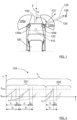
- FIG. 1 shows a vehicle 100 equipped with a vehicle radar system 110.
- the radar system 110 comprises a control unit 120 and at least one radar transceiver 130a, 130b, here a first corner radar transceiver 130a and a second corner radar transceiver 130b.
- radar transceivers such as a front center radar transceivers and rear radar transceivers; in this example only the front corner radar transceivers 130a, 130b, are discussed.
- the control unit 120 and at least one radar transceiver 130a, 130b may be comprised in a single physical unit or they may be distributed over more than one physical unit.
- Each ramp r 1 , r 2 lasts a certain ramp time t r , between two consecutive ramps there is the ramp time t r and a delay time t D that together form a total ramp time t T .
- Each radar transceiver 130a, 130b is associated with a corresponding field of view 135a, 135b.
- a boresight direction 137 of a corner radar transceiver 135b often coincides with a center line of the field of view 135b that points at an angle ⁇ compared to a forward direction F of the vehicle 100.
- a boresight direction normally coincides with the forward direction F of the vehicle 100.
- Radar transceivers 130a, 130b can for example be mounted behind a body part of the vehicle 100.
- This vehicle body part may be, e.g., a front bumper 150 or a rear bumper (not shown) as well as a separate radome, a grille and/or vehicle logo.
- the radar transceiver 130 comprises an antenna arrangement 140, a transmitter unit 131 and a receiver unit 132 that are connected to each other, to the antenna arrangement 140 and to the control unit 120.
- the control unit 120 comprises a radar control unit 133 that in turn comprises digital signal processing ability.
- the antenna arrangement 140 comprises a controllable transmitter antenna arrangement 141 and a receiver antenna arrangement 142.
- the transmitter antenna arrangement 141 comprising a first transmitter antenna column 143 and a second transmitter antenna column 144, each transmitter antenna column 143, 144 comprising a plurality of antenna elements 145.
- the receiver antenna arrangement 142 comprising a first receiver antenna column 146, a second receiver antenna column 147, a third receiver antenna column 148, and a fourth receiver antenna column 149, each receiver antenna column 146, 147, 148, 149 comprising a plurality of antenna elements 150.
- the transmitter antenna arrangement 141 In order to enable the transmitter antenna arrangement 141 to be controllable, it should comprise at least two transmitter antenna columns, according to some aspects spaced apart by a half wavelength at the operating frequency band, the antenna columns being adapted to transmit more or less simultaneously. According to some aspects, the transmitter unit 131 is adapted to configure individual phase shifts and power back-off values, possibly being controlled by the control unit 120.
- the receiver antenna arrangement 142 normally comprises a plurality of receiver antenna columns.
- the control unit 120 is adapted to control the radar transceiver 130 to generate and transmit a radar signal 124, and to receive a reflected radar signal 125 that corresponds to the transmitted radar signal 127 being reflected by one or more target objects 126.
- the control unit 120 is adapted to control the transmitter antenna arrangement 141 to generate a first antenna radiation pattern 160 for the transmitted radar signal 124, and to control the transmitter antenna arrangement 141 to generate a plurality of second antenna radiation patterns 161, 162, 163 for the transmitted radar signal 124.
- control unit 120 is adapted to control the radar transceiver 130 to transmit the radar signal 124 using the first antenna radiation pattern 160 for the first plurality 201 of FMCW ramps r 1 , and to transmit the radar signal 124 using the second antenna radiation patterns 162 for the second plurality 202 of FMCW ramps r 2 .
- the first antenna radiation pattern 160 will always be transmitted with the same antenna configuration; a constant phase shift and power back-off values being applied to the transmitter antenna columns 143, 144 by the transmitter unit 131.
- the phase shift and power back-off values that are applied to the transmitter antenna columns 143, 144 by the transmitter unit 131 are altered in set time intervals during a calibration process.
- control unit 120 is further adapted to determine which second antenna radiation pattern 162 provides the largest amplitude difference ⁇ A 2 of the received reflected signal 125 between the first antenna radiation pattern 160 and the second antenna radiation patterns 161, 162, 163, and to choose that second antenna radiation pattern 162.
- the first antenna radiation pattern 160 is of a first type
- the second antenna radiation patterns 161, 162, 163 are of a second type
- the second type is a delta pattern type, which means that there is a distinct amplitude dip at a certain angle, dividing each second antenna radiation pattern 161, 162, 163 into two more or less symmetrical parts.
- the amplitude dip is positioned at the predetermined angular direction ⁇ of 90°.
- the present disclosure can be applied to a dual-mode radar system, which applies time-division multiplexing to sense the environment with two different modes, a first mode for the first antenna pattern 160 and a second mode for the chosen second antenna radiation pattern 162.
- control unit 120 is adapted to control the transmitter antenna arrangement 141 to generate each second antenna radiation pattern 161, 162, 163 during a certain time interval when transmitting the radar signal 124.
- the control unit 120 when the control unit 120 is determining which second antenna radiation pattern 162 provides the largest amplitude difference ⁇ A 2 between the first antenna radiation pattern 160 and the second antenna radiation patterns 161, 162, 163, the control unit 120 is adapted to measure amplitudes of received reflected radar signals 125, and to compare amplitudes of received reflected radar signals 125 that correspond to when the first antenna radiation pattern 160 is used for the transmitted radar signal 124 with amplitudes of received reflected radar signals that correspond to when second antenna radiation patterns 161, 162, 163 are used for the transmitted radar signal 124.
- the control unit 120 is further adapted to determine which second antenna radiation pattern 161, 162, 163 is used when a difference ⁇ A 1 , ⁇ A 2 , ⁇ A 3 between the compared amplitudes is maximal.
- the method further comprises, in a predetermined angular direction ⁇ with respect to a predefined reference direction 137, F, determining S500 which second antenna radiation pattern 162 provides the largest amplitude difference ⁇ A 2 of the received reflected signal 125 between the first antenna radiation pattern 160 and the second antenna radiation patterns 161, 162, 163, and choosing that second antenna radiation pattern 162, and controlling S600 the transmitter antenna arrangement 141 to generate the chosen second antenna radiation pattern 162 and the first antenna radiation pattern 160 in an alternating manner.
- one of a first plurality 201 of FMCW ramps r 1 and a second plurality 202 of FMCW ramps r 2 follow after the other.
- the chirp signal 124 comprises repeating cycles of the first plurality 201 of frequency ramps r 1 and the second plurality 202 of frequency ramps r 2 .
- the determining S500 of which second antenna radiation pattern 162 provides the largest amplitude difference ⁇ A 2 between the first antenna radiation pattern 160 and the second antenna radiation patterns 161, 162, 163 further comprises measuring S510 amplitudes of received reflected radar signals 125, and comparing S520 amplitudes of received reflected radar signals 125 that correspond to when the first antenna radiation pattern 160 is used for the transmitted radar signal 124 with amplitudes of received reflected radar signals that correspond to when second antenna radiation patterns 161, 162, 163 are used for the transmitted radar signal 124.
- the determining S500 further comprises determining S530 which second antenna radiation pattern 161, 162, 163 is used when a difference ⁇ A 1 , ⁇ A 2 , ⁇ A 3 between the compared amplitudes is maximal.
- Processing circuitry 801 is provided using any combination of one or more of a suitable central processing unit (CPU), multiprocessor, microcontroller, digital signal processor (DSP), etc., capable of executing software instructions stored in a computer program product, e.g. in the form of a storage medium 802.
- the processing circuitry 801 may further be provided as at least one application specific integrated circuit (ASIC), or field programmable gate array (FPGA).
- ASIC application specific integrated circuit
- FPGA field programmable gate array
- the control unit arrangement 3 may further comprise a communications interface 803 for communications with at least one external device such as for example radar transceivers.
- the communication interface 803 may comprise one or more transmitters and receivers, comprising analogue and digital components and a suitable number ports for wireline or wireless communication.
- the present disclosure is not limited to the examples described above, but may vary freely within the scope of the appended claims.
- the above description mainly has been directed towards corner radar transceivers 130a, 130b and exemplified for front corner radar transceivers 130a, 130b
- the present disclosure can be applied for any radar transceiver such as front, side and rear radar transceivers, and for any combination of radar transceivers.
Landscapes
- Engineering & Computer Science (AREA)
- Radar, Positioning & Navigation (AREA)
- Remote Sensing (AREA)
- Physics & Mathematics (AREA)
- Computer Networks & Wireless Communication (AREA)
- General Physics & Mathematics (AREA)
- Electromagnetism (AREA)
- Computer Security & Cryptography (AREA)
- Radar Systems Or Details Thereof (AREA)
Abstract
Description
- The present disclosure relates to radar transceivers and in particular to installation of radar transceivers in vehicles.
- A radar transceiver is a device arranged for transmission and reception of radar signals in a radar frequency band. Radar transceivers are commonly used in vehicles for monitoring vehicle surroundings. Automatic Cruise Control (ACC) functions, Emergency Braking (EB) functions, Advanced Driver Assistance Systems (ADAS) and Autonomous Drive (AD) are some examples of applications where radar data represents an important source of information on which vehicle control may be based. Some radar transceivers are placed in vehicle rear corners and are also used for Blind Spot Monitoring (BSM) and Automatic Lane Change (ALC).
- Vehicle radar transceivers are often arranged hidden behind vehicle body parts, such as a front or a rear vehicle bumper. This placement is often chosen due to aesthetic reasons, but there is also a need to protect the radar transceiver from mechanical impact, moisture and dirt.
- A drawback associated with hiding radar transceivers behind vehicle body parts is that the radar transmission must penetrate the body part in order to monitor the vehicle surroundings. This impacts wave propagation and sensor performance because the second surface material distorts transmitted signals, TX signals, and received signals, RX signals. There can also be mounting effects where the mounting of a radar transceiver affects its performance. This can partly be compensated for by means of calibrating the radar transceiver.
- Calibration of radar transceiver is normally time consuming, costly and prone to errors, needing a controlled environment at the end of a vehicle production line.
- It is an object of the present disclosure to provide an improved radar transceiver calibration process that enables an enhanced normal operation following the calibration process.
- This object is achieved by means of a vehicle radar system that comprises a control unit and a radar transceiver that in turn comprises a controllable transmitter antenna arrangement and a receiver antenna arrangement. The control unit is adapted to control the radar transceiver to generate and transmit a radar signal, and to receive a reflected radar signal that corresponds to the transmitted radar signal being reflected by one or more target objects. The control unit is further adapted to control the transmitter antenna arrangement to generate a first antenna radiation pattern for the transmitted radar signal, and to control the transmitter antenna arrangement to generate a plurality of second antenna radiation patterns for the transmitted radar signal.
- In a predetermined angular direction with respect to a predefined reference direction, the control unit is further adapted to determine which second antenna radiation pattern that provides the largest amplitude difference between the first antenna radiation pattern and the second antenna radiation patterns, and to choose that second antenna radiation pattern. The calibration process has now been finalized and resulted in the chosen second antenna radiation pattern and a normal running mode is about to start. The control unit is then adapted to control the transmitter antenna arrangement to generate the chosen second antenna radiation pattern and the first antenna radiation pattern in an alternating manner.
- This means that an uncomplicated and efficient calibration process is provided, not needing a controlled environment. The present disclosure can be applied to a dual-mode radar system, which applies time-division multiplexing to sense the environment with two different modes, a first mode for the first antenna pattern and a second mode for the chosen second antenna radiation pattern.
- According to some aspects, each vehicle radar transceiver is arranged to generate and transmit radar signals in the form of frequency modulated continuous wave (FMCW) signals. The control unit is adapted to control the radar transceiver to transmit the radar signal using the first antenna radiation pattern for a first plurality of FMCW ramps, and to transmit the radar signal using the second antenna radiation pattern for a second plurality of FMCW ramps. Each radar cycle has a duration of a cycle time.
- This means that the present disclosure is applicable for the well-known FMCW radar technology.
- According to some aspects, one of a first plurality of FMCW ramps and a second plurality of FMCW ramps follow after the other. According to some further aspects, during one or more radar cycles, the chirp signal comprises repeating cycles of the first plurality of frequency ramps and the second plurality of frequency ramps.
- This means that the first plurality of FMCW ramps and the second plurality of FMCW ramps can come in any order. This is the case for the calibration process as well as for the normal operation after calibration.
- Furthermore, this also means that during the calibration process, one or more sets of a first antenna radiation pattern and one second antenna radiation pattern can be generated in one and the same radar cycle. This can be accomplished in one radar cycle or distributed in several radar cycles. These sets thus result in that the first antenna radiation pattern is repeatedly generated before each second antenna radiation pattern is generated.
- According to some aspects, the control unit is adapted to control the transmitter antenna arrangement to generate each second antenna radiation pattern during a certain time interval when transmitting the radar signal.
- In this way, a controlled calibration procedure is obtained.
- According to some aspects, the control unit is adapted to determine which second antenna radiation pattern provides the largest amplitude difference between the first antenna radiation pattern and the second antenna radiation patterns by further being adapted to measure amplitudes of received reflected radar signals in the predetermined angular direction, and to compare amplitudes of received reflected radar signals that correspond to when the first antenna radiation pattern is used for the transmitted radar signal with amplitudes of received reflected radar signals that correspond to when second antenna radiation patterns are used for the transmitted radar signal. The control unit is then further adapted to determine which second antenna radiation pattern is used when a difference between the compared amplitudes is maximal.
- This means that radar targets in the azimuth area of interest, i.e., a field of view or a certain predetermined optimization azimuth angle, are selected, and their received amplitudes are analyzed.
- The intention of the comparison is to find an ideal notch position for the chosen second antenna radiation pattern, where this comparison is independent of the targets' reflective properties, since the same selected targets can be used.
- According to some aspects, the vehicle radar system comprises at least one transmitter unit, where the transmitter antenna arrangement comprises at least two first transmitter antenna columns, each transmitter antenna column comprising a plurality of antenna elements, and where the transmitter unit is adapted to transmit via the transmitter antenna columns simultaneously.
- This enables the transmitter antenna arrangement to be controllable.
- Further advantages are obtained by the dependent claims.
- There are also disclosed herein methods and vehicles associated with the above-mentioned advantages.
- The present disclosure will now be described more in detail with reference to the appended drawings, where:
- Figure 1
- shows a schematic top view of a vehicle;
- Figure 2
- illustrates an FMCW radar signal;
- Figure 3
- shows a schematic front view of an antenna arrangement;
- Figure 4
- illustrates a first example of antenna radiation patterns;
- Figure 5
- illustrates a second example of antenna radiation patterns;
- Figure 6
- illustrates a third example of antenna radiation patterns;
- Figure 7
- is a flow chart illustrating methods according to the present disclosure;
- Figure 8
- schematically illustrates a control unit arrangement; and
- Figure 9
- shows a computer program product.
- The inventive concept will now be described more fully hereinafter with reference to the accompanying drawings, in which certain embodiments of the inventive concept are shown.
- This inventive concept may, however, be embodied in many different forms and should not be construed as limited to the embodiments set forth herein; rather, these embodiments are provided by way of example so that this disclosure will be thorough and complete, and will fully convey the scope of the inventive concept to those skilled in the art. Like numbers refer to like elements throughout the description.
-
Figure 1 shows avehicle 100 equipped with avehicle radar system 110. Theradar system 110 comprises acontrol unit 120 and at least oneradar transceiver corner radar transceiver 130a and a secondcorner radar transceiver 130b. - There are often more radar transceivers, such as a front center radar transceivers and rear radar transceivers; in this example only the front
corner radar transceivers - The
control unit 120 and at least oneradar transceiver - According to an example, the
vehicle radar transceivers radar signals 124 in the form of frequency modulated continuous wave (FMCW) signals, sometimes also referred to as radar chirp signals, and to receive reflected radar signals 125, where the transmitted signals have been reflected by anobject 126. - This is illustrated in
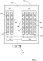
Figure 2 , where the transmittedradar signal 124 is in the form of a chirp signal that comprises ramps r1, r2 where the frequency f varies from a first frequency fstart to a second frequency fstop over the course of each ramp r1, r2, where the value of the first frequency fstart falls below the value of the second frequency fstop. For a radar cycle, thechirp signal 124 comprises repeating cycles of afirst plurality 201 of frequency ramps r1 and asecond plurality 202 of frequency ramps r2, where each radar cycle has a duration of a cycle time tc. In this context, a radar cycle is one observation phase during which thevehicle radar system 110 is arranged to acquire data, process said data on several signal processing levels and to send out available results. This can be a fixed time interval or a dynamic time interval depending on environment conditions and processing load. - Each ramp r1, r2 lasts a certain ramp time tr, between two consecutive ramps there is the ramp time tr and a delay time tD that together form a total ramp time tT.
- The present disclosure is not limited to FMCW radar waveforms. Rather, the disclosed concepts and techniques can be applied to many different radar waveforms. In particular, the techniques disclosed herein are applicable to Orthogonal Frequency Division Multiplex (OFDM) radar, and to Pulse Modulated Continuous Wave (PMCW) radar. One example of OFDM radar is the stepped OFDM radar waveform described in
EP3323151 A1 . - Each
radar transceiver view corner radar transceiver 135b, aboresight direction 137 of acorner radar transceiver 135b often coincides with a center line of the field ofview 135b that points at an angle α compared to a forward direction F of thevehicle 100. For a front center radar transceiver (not shown), a boresight direction normally coincides with the forward direction F of thevehicle 100. -
Radar transceivers vehicle 100. This vehicle body part may be, e.g., afront bumper 150 or a rear bumper (not shown) as well as a separate radome, a grille and/or vehicle logo. - In the following, a
corner radar transceiver 130 will be discussed, and it is to be understood that the features discussed are applicable for anycorner radar transceiver - With reference to
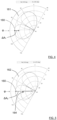
Figure 3 , theradar transceiver 130 comprises anantenna arrangement 140, atransmitter unit 131 and areceiver unit 132 that are connected to each other, to theantenna arrangement 140 and to thecontrol unit 120. Thecontrol unit 120 comprises aradar control unit 133 that in turn comprises digital signal processing ability. - The
antenna arrangement 140 comprises a controllabletransmitter antenna arrangement 141 and areceiver antenna arrangement 142. According to some aspects, thetransmitter antenna arrangement 141 comprising a firsttransmitter antenna column 143 and a secondtransmitter antenna column 144, eachtransmitter antenna column antenna elements 145. According to some further aspects, thereceiver antenna arrangement 142 comprising a firstreceiver antenna column 146, a secondreceiver antenna column 147, a thirdreceiver antenna column 148, and a fourthreceiver antenna column 149, eachreceiver antenna column antenna elements 150. - In order to enable the
transmitter antenna arrangement 141 to be controllable, it should comprise at least two transmitter antenna columns, according to some aspects spaced apart by a half wavelength at the operating frequency band, the antenna columns being adapted to transmit more or less simultaneously. According to some aspects, thetransmitter unit 131 is adapted to configure individual phase shifts and power back-off values, possibly being controlled by thecontrol unit 120. - Generally, the
receiver antenna arrangement 142 normally comprises a plurality of receiver antenna columns. - The
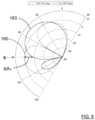
control unit 120 is adapted to control theradar transceiver 130 to generate and transmit aradar signal 124, and to receive a reflectedradar signal 125 that corresponds to the transmitted radar signal 127 being reflected by one or more target objects 126. With reference also toFigure 4-6 , for a calibration process, thecontrol unit 120 is adapted to control thetransmitter antenna arrangement 141 to generate a firstantenna radiation pattern 160 for the transmittedradar signal 124, and to control thetransmitter antenna arrangement 141 to generate a plurality of secondantenna radiation patterns radar signal 124. - In
Figure 4-6 theantenna radiation patterns corner radar transceiver 130. - According to some aspects, during the calibration process, the
control unit 120 is adapted to control theradar transceiver 130 to transmit theradar signal 124 using the firstantenna radiation pattern 160 for thefirst plurality 201 of FMCW ramps r1, and to transmit theradar signal 124 using the secondantenna radiation patterns 162 for thesecond plurality 202 of FMCW ramps r2. - According to some aspects, the first
antenna radiation pattern 160 will always be transmitted with the same antenna configuration; a constant phase shift and power back-off values being applied to thetransmitter antenna columns transmitter unit 131. For the secondantenna radiation patterns transmitter antenna columns transmitter unit 131 are altered in set time intervals during a calibration process. - In a predetermined angular direction ϕ with respect to a predefined reference direction such as for example a vehicle boresight direction that corresponds to the forward direction F or an
antenna boresight direction 137, thecontrol unit 120 is further adapted to determine which secondantenna radiation pattern 162 provides the largest amplitude difference ΔA2 of the received reflectedsignal 125 between the firstantenna radiation pattern 160 and the secondantenna radiation patterns antenna radiation pattern 162. - In this manner, by determining a chosen second
antenna radiation pattern 162, the calibration process has been completed. The calibration process is normally independent of the environment, which is an advantage. According to some aspects, the largest amplitude difference ΔA2 corresponds to anotch 164 at the chosen secondantenna radiation pattern 162 in the predetermined angular direction ϕ. This possibility is illustrated inFigure 5 . - The chosen second
antenna radiation pattern 162 can now be used during normal operation. This means that thecontrol unit 120 is adapted to control thetransmitter antenna arrangement 141 to generate the chosen secondantenna radiation pattern 162 and the firstantenna radiation pattern 160 in an alternating manner. - In this context, according to some aspects, the first
antenna radiation pattern 160 is of a first type, and the secondantenna radiation patterns antenna radiation pattern Figure 5 , the amplitude dip is positioned at the predetermined angular direction ϕ of 90°. - The first
antenna radiation pattern 160 can be of any suitable type, but should preferably not have any distinct amplitude dip at the predetermined angular direction ϕ. The firstantenna radiation pattern 160 does not need to have any distinct amplitude dip at all, in the present example with reference toFigure 4-6 the firstantenna radiation pattern 160 has a distinct amplitude dip at about 60°. For the firstantenna radiation pattern 160 this is in the middle of the field of view (FOV), which maximizes the energy transmitted at the edges of the FOV. - According to some aspects, during normal operation after calibration, the
control unit 120 is adapted to control theradar transceiver 130 to transmit theradar signal 124 using the firstantenna radiation pattern 160 for thefirst plurality 201 of FMCW ramps r1, and to transmit theradar signal 124 using the chosen secondantenna radiation pattern 162 for thesecond plurality 202 of FMCW ramps r2. - This means that the present disclosure can be applied to a dual-mode radar system, which applies time-division multiplexing to sense the environment with two different modes, a first mode for the
first antenna pattern 160 and a second mode for the chosen secondantenna radiation pattern 162. - According to some aspects, one of a
first plurality 201 of FMCW ramps r1 and asecond plurality 202 of FMCW ramps r2 follow after the other. According to some further aspects, during one or more radar cycles, thechirp signal 124 comprises repeating cycles of thefirst plurality 201 of frequency ramps r1 and thesecond plurality 202 of frequency ramps r2. These cycles can thus be sub-cycles in a radar cycle, or correspond to a radar cycle. - This means that the
first plurality 201 of FMCW ramps r1 and thesecond plurality 202 of FMCW ramps r2 can come in any order. This is the case for the calibration process as well as for the normal operation after calibration. - Furthermore, according to some aspects, during the calibration process, one or more sets of a first
antenna radiation pattern 160 and one secondantenna radiation pattern antenna radiation pattern 160 is repeatedly generated before each secondantenna radiation pattern - According to some further aspects, during the calibration process, one first
antenna radiation pattern 160 is followed by all secondantenna radiation pattern - According to some aspects, the
control unit 120 is adapted to control thetransmitter antenna arrangement 141 to generate each secondantenna radiation pattern radar signal 124. - In this way, a controlled calibration procedure is obtained.
- According to some aspects, when the
control unit 120 is determining which secondantenna radiation pattern 162 provides the largest amplitude difference ΔA2 between the firstantenna radiation pattern 160 and the secondantenna radiation patterns control unit 120 is adapted to measure amplitudes of received reflected radar signals 125, and to compare amplitudes of received reflected radar signals 125 that correspond to when the firstantenna radiation pattern 160 is used for the transmittedradar signal 124 with amplitudes of received reflected radar signals that correspond to when secondantenna radiation patterns radar signal 124. Thecontrol unit 120 is further adapted to determine which secondantenna radiation pattern - This means that radar targets 126 in the azimuth area of interest, i.e., a field of
view - For the first
antenna radiation pattern 160 and the different secondantenna radiation patterns signal 125 are compared, such that at an ideal notch position for the chosen secondantenna radiation pattern 162, at the predetermined angular direction ϕ, the amplitude ratio has reached a maximum. This comparison is independent of the targets' reflective properties, since the same selectedtargets 126 are used. According to some aspects, a systematic beamsteering sweep can be used for the transmittedradar signal 124 to find the ideal notch position for the secondantenna radiation pattern - With reference to
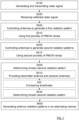
Figure 7 , the present disclosure relates to a method for calibrating and operating aradar transceiver 130 used in avehicle radar system 110 that is mounted to avehicle 100, where theradar transceiver 130 comprises a controllabletransmitter antenna arrangement 141 and areceiver antenna arrangement 142. The method comprises generating and transmitting S100 aradar signal 124, and receiving S200 a reflectedradar signal 125 that corresponds to the transmittedradar signal 124 being reflected by one or more target objects 126. - The method further comprises controlling S300 the
transmitter antenna arrangement 141 to generate a firstantenna radiation pattern 160 for the transmittedradar signal 124; and controlling S400 thetransmitter antenna arrangement 141 to generate a plurality of secondantenna radiation patterns radar signal 124. - The method further comprises, in a predetermined angular direction ϕ with respect to a
predefined reference direction 137, F, determining S500 which secondantenna radiation pattern 162 provides the largest amplitude difference ΔA2 of the received reflectedsignal 125 between the firstantenna radiation pattern 160 and the secondantenna radiation patterns antenna radiation pattern 162, and controlling S600 thetransmitter antenna arrangement 141 to generate the chosen secondantenna radiation pattern 162 and the firstantenna radiation pattern 160 in an alternating manner. - The
predefined reference direction 137 can for example be a vehicle boresight direction that corresponds to the forward direction F or anantenna boresight direction 137. - According to some aspects, the method further comprises using
radar signals 124 in the form of frequency modulated continuous wave, FMCW, ramps. For each radar cycle, the method comprises transmitting S310 theradar signal 124 using the firstantenna radiation pattern 160 for afirst plurality 201 of FMCW ramps r1, and transmitting S410 theradar signal 124 using the secondantenna radiation pattern second plurality 202 of FMCW ramps r2. Each radar cycle has a duration of a cycle time tc. - According to some aspects, one of a
first plurality 201 of FMCW ramps r1 and asecond plurality 202 of FMCW ramps r2 follow after the other. - According to some aspects, during one or more radar cycles, the
chirp signal 124 comprises repeating cycles of thefirst plurality 201 of frequency ramps r1 and thesecond plurality 202 of frequency ramps r2. - According to some aspects, each second
antenna radiation pattern radar signal 124. - According to some aspects, the determining S500 of which second
antenna radiation pattern 162 provides the largest amplitude difference ΔA2 between the firstantenna radiation pattern 160 and the secondantenna radiation patterns antenna radiation pattern 160 is used for the transmittedradar signal 124 with amplitudes of received reflected radar signals that correspond to when secondantenna radiation patterns radar signal 124. The determining S500 further comprises determining S530 which secondantenna radiation pattern -
Figure 8 schematically illustrates acontrol unit arrangement 800, such as thecontrol unit 120 according to the above and according to aspects of the present disclosure. It is appreciated that the above described methods and techniques may be realized in hardware. This hardware is then arranged to perform the methods, whereby the same advantages and effects are obtained as have been discussed above. -
Processing circuitry 801 is provided using any combination of one or more of a suitable central processing unit (CPU), multiprocessor, microcontroller, digital signal processor (DSP), etc., capable of executing software instructions stored in a computer program product, e.g. in the form of astorage medium 802. Theprocessing circuitry 801 may further be provided as at least one application specific integrated circuit (ASIC), or field programmable gate array (FPGA). - Particularly, the
processing circuitry 801 is configured to cause thecontrol unit arrangement 800 to perform a set of operations, or steps, for example the methods described above. For example, thestorage medium 802 may store the set of operations, and theprocessing circuitry 801 may be configured to retrieve the set of operations from thestorage medium 802 to cause the control unit arrangement 3 to perform the set of operations. The set of operations may be provided as a set of executable instructions. Thus, theprocessing circuitry 801 is thereby arranged to execute methods as herein disclosed. - The
storage medium 802 may also comprise persistent storage, which, for example, can be any single one or combination of magnetic memory, optical memory, solid state memory or even remotely mounted memory. - The control unit arrangement 3 may further comprise a
communications interface 803 for communications with at least one external device such as for example radar transceivers. As such thecommunication interface 803 may comprise one or more transmitters and receivers, comprising analogue and digital components and a suitable number ports for wireline or wireless communication. - The
processing circuitry 801 controls the general operation of the control unit arrangement 3, e.g. by sending data and control signals to thecommunication interface 803 and thestorage medium 802, by receiving data and reports from thecommunication interface 803, and by retrieving data and instructions from thestorage medium 802. Other components, as well as the related functionality, of the unit are omitted in order not to obscure the concepts presented herein. -
Figure 9 schematically illustrates acomputer program product 900 comprising acomputer program 901 according to the disclosure above, and a computerreadable storage medium 902 on which thecomputer program 901 is stored. - The present disclosure is not limited to the examples described above, but may vary freely within the scope of the appended claims. For example, although the above description mainly has been directed towards
corner radar transceivers corner radar transceivers - The
control unit 120 is part of theradar system 110 and can, but does not need to, be part of one or more radar transceivers. According to some aspects, when thecontrol unit 120 is part of a radar transceiver and is adapted to control a radar transceiver, this is to be interpreted as thecontrol unit 120 being adapted to control the rest of that radar transceiver.
Claims (15)
- A method for calibrating and operating a radar transceiver (130) used in a vehicle radar system (110) that is mounted to a vehicle (100), where the radar transceiver (130) comprises a controllable transmitter antenna arrangement (141) and a receiver antenna arrangement (142), where the method comprisesgenerating and transmitting (S100) a radar signal (124) ;receiving (S200) a reflected radar signal (125) that corresponds to the transmitted radar signal (124) being reflected by one or more target objects (126); wherein, the method further comprises;controlling (S300) the transmitter antenna arrangement (141) to generate a first antenna radiation pattern (160) for the transmitted radar signal (124); and,controlling (S400) the transmitter antenna arrangement (141) to generate a plurality of second antenna radiation patterns (161, 162, 163) for the transmitted radar signal (124);in a predetermined angular direction (ϕ) with respect to predefined reference direction (F, 137), determining (S500) which second antenna radiation pattern (162) provides the largest amplitude difference (ΔA2) of the received reflected signal (125) between the first antenna radiation pattern (160) and the second antenna radiation patterns (161, 162, 163), and choosing that second antenna radiation pattern (162); andcontrolling (S600) the transmitter antenna arrangement (141) to generate the chosen second antenna radiation pattern (162) and the first antenna radiation pattern (160) in an alternating manner.
- The method according to claim 1, wherein the method further comprises using radar signals (124) in the form of frequency modulated continuous wave, FMCW, ramps, where, for each radar cycle, the method comprises:transmitting (S310) the radar signal (124) using the first antenna radiation pattern (160) for a first plurality (201) of FMCW ramps (r1); andtransmitting (S410) the radar signal (124) using the second antenna radiation pattern (161, 162, 163) for a second plurality (202) of FMCW ramps (r2),where each radar cycle has a duration of a cycle time (tc).
- The method according to claim 2, wherein one of a first plurality (201) of FMCW ramps (r1) and a second plurality (202) of FMCW ramps (r2) follow after the other.
- The method according to any one of the claims 2 or 3, wherein during one or more radar cycles, the chirp signal (124) comprises repeating cycles of the first plurality (201) of frequency ramps (r1) and the second plurality (202) of frequency ramps (r2) .
- The method according to any one of the previous claims, wherein each second antenna radiation pattern (161, 162, 163) is used during a certain time interval when transmitting the radar signal (124).
- The method according to any one of the previous claims, wherein the determining (S500) of which second antenna radiation pattern (162) that provides the largest amplitude difference (ΔA2) between the first antenna radiation pattern (160) and the second antenna radiation patterns (161, 162, 163) further comprises:measuring (S510) amplitudes of received reflected radar signals (125) in the predetermined angular direction (ϕ);comparing (S520) amplitudes of received reflected radar signals (125) that correspond to when the first antenna radiation pattern (160) is used for the transmitted radar signal (124) with amplitudes of received reflected radar signals that correspond to when second antenna radiation patterns (161, 162, 163) are used for the transmitted radar signal (124); anddetermining (S530) which second antenna radiation pattern (161, 162, 163) is used when a difference (ΔA1, ΔA2, ΔA3) between the compared amplitudes is maximal.
- A vehicle radar system (110) that comprises a control unit (120) and a radar transceiver (130) that in turn comprises a controllable transmitter antenna arrangement (141) and a receiver antenna arrangement (142), where the control unit (120) is adapted to control the radar transceiver (130) to- generate and transmit a radar signal (124), and- receive a reflected radar signal (125) that corresponds to the transmitted radar signal (124) being reflected by one or more target objects (126),wherein, the control unit (120) is adapted to- control the transmitter antenna arrangement (141) to generate a first antenna radiation pattern (160) for the transmitted radar signal (124),- control the transmitter antenna arrangement (141) to generate a plurality of second antenna radiation patterns (161, 162, 163) for the transmitted radar signal (124),- in a predetermined angular direction (ϕ) with respect to a predefined reference direction (F, 137), to determine which second antenna radiation pattern (162) that provides the largest amplitude difference (ΔA2) between the first antenna radiation pattern (160) and the second antenna radiation patterns (161, 162, 163), and to choose that second antenna radiation pattern (162), and to- control the transmitter antenna arrangement (141) to generate the chosen second antenna radiation pattern (162) and the first antenna radiation pattern (160) in an alternating manner.
- The vehicle radar system (110) according to claim 7, wherein each vehicle radar transceiver (130a, 130b) is arranged to generate and transmit radar signals (124) in the form of frequency modulated continuous wave, FMCW, signals, where the control unit (120) is adapted to control the radar transceiver (130a, 130b) to transmit the radar signal (124) using the first antenna radiation pattern (160) for a first plurality (201) of FMCW ramps (r1), and to transmit the radar signal (124) using the second antenna radiation pattern (161, 162, 163) for a second plurality (202) of FMCW ramps (r2), where each radar cycle has a duration of a cycle time (tc).
- The vehicle radar system (110) according to claim 8, wherein one of a first plurality (201) of FMCW ramps (r1) and a second plurality (202) of FMCW ramps (r2) follow after the other.
- The vehicle radar system (110) according to any one of the claims 8 or 9, wherein during one or more radar cycles, the chirp signal (124) comprises repeating cycles of the first plurality (201) of frequency ramps (r1) and the second plurality (202) of frequency ramps (r2).
- The vehicle radar system (110) according to any one of the claims 7-10, wherein the control unit (120) is adapted to control the transmitter antenna arrangement (141) to generate each second antenna radiation pattern (161, 162, 163) during a certain time interval when transmitting the radar signal (124).
- The vehicle radar system (110) according to any one of the claims 7-11, wherein the control unit (120) is adapted to determine which second antenna radiation pattern (162) provides the largest amplitude difference (ΔA2) between the first antenna radiation pattern (160) and the second antenna radiation patterns (161, 162, 163) by further being adapted to- measure amplitudes of received reflected radar signals (125) in the predetermined angular direction (ϕ),- compare amplitudes of received reflected radar signals (125) that correspond to when the first antenna radiation pattern (160) is used for the transmitted radar signal (124) with amplitudes of received reflected radar signals that correspond to when second antenna radiation patterns (161, 162, 163) are used for the transmitted radar signal (124), and to- determine which second antenna radiation pattern 161, 162, 163 is used when a difference ΔA1, ΔA2, ΔA3 between the compared amplitudes is maximal.
- The vehicle radar system (110) according to any one of the claims 7-12, wherein the vehicle radar system (110) comprises at least one transmitter unit (131), where the transmitter antenna arrangement (141) comprises at least two first transmitter antenna columns (143, 144), each transmitter antenna column (143, 144) comprising a plurality of antenna elements (145), and where the transmitter unit (131) is adapted to transmit via the transmitter antenna columns (143, 144) simultaneously.
- The vehicle radar system (110) according to claim 13, wherein the transmitter unit (131) is adapted to configure individual phase shifts and power back-off values.
- A vehicle (100) comprising the vehicle radar system (110) according to any one of the claims 7-14.
Priority Applications (4)
| Application Number | Priority Date | Filing Date | Title |
|---|---|---|---|
| EP21204673.4A EP4174516A1 (en) | 2021-10-26 | 2021-10-26 | Radar transceiver calibration |
| US18/701,707 US20250231279A1 (en) | 2021-10-26 | 2022-10-20 | Radar transceiver calibration |
| CN202280066861.2A CN118176433A (en) | 2021-10-26 | 2022-10-20 | Radar transceiver calibration |
| PCT/EP2022/079169 WO2023072713A1 (en) | 2021-10-26 | 2022-10-20 | Radar transceiver calibration |
Applications Claiming Priority (1)
| Application Number | Priority Date | Filing Date | Title |
|---|---|---|---|
| EP21204673.4A EP4174516A1 (en) | 2021-10-26 | 2021-10-26 | Radar transceiver calibration |
Publications (1)
| Publication Number | Publication Date |
|---|---|
| EP4174516A1 true EP4174516A1 (en) | 2023-05-03 |
Family
ID=78413621
Family Applications (1)
| Application Number | Title | Priority Date | Filing Date |
|---|---|---|---|
| EP21204673.4A Pending EP4174516A1 (en) | 2021-10-26 | 2021-10-26 | Radar transceiver calibration |
Country Status (4)
| Country | Link |
|---|---|
| US (1) | US20250231279A1 (en) |
| EP (1) | EP4174516A1 (en) |
| CN (1) | CN118176433A (en) |
| WO (1) | WO2023072713A1 (en) |
Cited By (1)
| Publication number | Priority date | Publication date | Assignee | Title |
|---|---|---|---|---|
| US20240088930A1 (en) * | 2022-09-08 | 2024-03-14 | Mediatek Inc. | Dynamic tuning method for sar and user equipment thereof |
Citations (5)
| Publication number | Priority date | Publication date | Assignee | Title |
|---|---|---|---|---|
| WO2012089385A1 (en) * | 2010-12-29 | 2012-07-05 | Robert Bosch Gmbh | Radar sensor for motor vehicles |
| DE102014014864A1 (en) * | 2014-10-06 | 2016-04-07 | Astyx Gmbh | Imaging radar sensor with horizontal digital beamforming and vertical object measurement by phase comparison with staggered transmitters |
| US20160209504A1 (en) * | 2013-08-27 | 2016-07-21 | Robert Bosch Gmbh | Radar sensor for motor vehicles |
| EP3323151A1 (en) | 2015-07-16 | 2018-05-23 | Aledia | Optoelectronic device comprising three-dimensional semiconductor elements, and method for manufacturing said device |
| US20200249344A1 (en) * | 2019-02-01 | 2020-08-06 | Mando Corporation | Radar sensor apparatus for vehicle, object detecting method, and antenna apparatus therefor |
Family Cites Families (3)
| Publication number | Priority date | Publication date | Assignee | Title |
|---|---|---|---|---|
| US9608305B2 (en) * | 2014-01-14 | 2017-03-28 | Infineon Technologies Ag | System and method for a directional coupler with a combining circuit |
| US11789116B2 (en) * | 2019-09-24 | 2023-10-17 | International Business Machines Corporation | Multi-direction phased array calibration |
| EP3862772A1 (en) * | 2020-02-04 | 2021-08-11 | Aptiv Technologies Limited | Radar device |
-
2021
- 2021-10-26 EP EP21204673.4A patent/EP4174516A1/en active Pending
-
2022
- 2022-10-20 US US18/701,707 patent/US20250231279A1/en active Pending
- 2022-10-20 CN CN202280066861.2A patent/CN118176433A/en active Pending
- 2022-10-20 WO PCT/EP2022/079169 patent/WO2023072713A1/en not_active Ceased
Patent Citations (5)
| Publication number | Priority date | Publication date | Assignee | Title |
|---|---|---|---|---|
| WO2012089385A1 (en) * | 2010-12-29 | 2012-07-05 | Robert Bosch Gmbh | Radar sensor for motor vehicles |
| US20160209504A1 (en) * | 2013-08-27 | 2016-07-21 | Robert Bosch Gmbh | Radar sensor for motor vehicles |
| DE102014014864A1 (en) * | 2014-10-06 | 2016-04-07 | Astyx Gmbh | Imaging radar sensor with horizontal digital beamforming and vertical object measurement by phase comparison with staggered transmitters |
| EP3323151A1 (en) | 2015-07-16 | 2018-05-23 | Aledia | Optoelectronic device comprising three-dimensional semiconductor elements, and method for manufacturing said device |
| US20200249344A1 (en) * | 2019-02-01 | 2020-08-06 | Mando Corporation | Radar sensor apparatus for vehicle, object detecting method, and antenna apparatus therefor |
Cited By (2)
| Publication number | Priority date | Publication date | Assignee | Title |
|---|---|---|---|---|
| US20240088930A1 (en) * | 2022-09-08 | 2024-03-14 | Mediatek Inc. | Dynamic tuning method for sar and user equipment thereof |
| US12224786B2 (en) * | 2022-09-08 | 2025-02-11 | Mediatek Inc. | Dynamic tuning method for SAR and user equipment thereof |
Also Published As
| Publication number | Publication date |
|---|---|
| CN118176433A (en) | 2024-06-11 |
| US20250231279A1 (en) | 2025-07-17 |
| WO2023072713A1 (en) | 2023-05-04 |
Similar Documents
| Publication | Publication Date | Title |
|---|---|---|
| CN102135616B (en) | Integrated radar apparatus and integrated antenna apparatus | |
| KR102746695B1 (en) | Radar Sensor Apparatus for Vehicle and Object Detecting Method, Antenna Apparatus therefor | |
| KR102667977B1 (en) | Radar Apparatus for Vehicle and Controlling Method thereof | |
| US9500745B2 (en) | Radar sensor for motor vehicles | |
| KR20110126939A (en) | Integrated Radar System and Vehicle Control System | |
| WO2012030615A2 (en) | Multi-range radar system | |
| US11796630B2 (en) | MIMO channel extenders with associated systems and methods | |
| US20130271310A1 (en) | On-board radar apparatus, detection method, and detection program | |
| CN113625279A (en) | Apparatus and method for detecting vertical mounting misalignment of radar apparatus and radar apparatus having the same | |
| US11802960B2 (en) | Phase correcting apparatus and method of transmission signal of vehicle radar, and vehicle radar apparatus with the same | |
| KR102859817B1 (en) | Apparatus and Method for Detecting Performance Degradation of Radar Apparatus for Vehicle, and Radar Apparatus of Vehicle with the same | |
| US20250231279A1 (en) | Radar transceiver calibration | |
| US12517240B2 (en) | Radar apparatus and method for detecting object based on occurrence of event | |
| US20210325506A1 (en) | Electronic device, method for controlling electronic device, and electronic device control program | |
| US11709226B2 (en) | Calibrating array antennas based on signal energy distribution as a function of velocity | |
| JP2011013182A (en) | Target detector and method of detecting target | |
| EP3819662A1 (en) | A vehicle radar with frequency diversity | |
| US12607734B2 (en) | Radar device and radar method | |
| KR20120106567A (en) | Radar apparatus supporting short and long range radar operation | |
| US12164057B2 (en) | Calibrating array antennas based on signal energy distribution as a function of angle | |
| KR20220089824A (en) | Smart sensor device for detecting obstacles in mobile devices | |
| KR20230062055A (en) | Multi-channel radar sensor apparatus |
Legal Events
| Date | Code | Title | Description |
|---|---|---|---|
| PUAI | Public reference made under article 153(3) epc to a published international application that has entered the european phase |
Free format text: ORIGINAL CODE: 0009012 |
|
| STAA | Information on the status of an ep patent application or granted ep patent |
Free format text: STATUS: THE APPLICATION HAS BEEN PUBLISHED |
|
| AK | Designated contracting states |
Kind code of ref document: A1 Designated state(s): AL AT BE BG CH CY CZ DE DK EE ES FI FR GB GR HR HU IE IS IT LI LT LU LV MC MK MT NL NO PL PT RO RS SE SI SK SM TR |
|
| STAA | Information on the status of an ep patent application or granted ep patent |
Free format text: STATUS: REQUEST FOR EXAMINATION WAS MADE |
|
| 17P | Request for examination filed |
Effective date: 20231024 |
|
| RBV | Designated contracting states (corrected) |
Designated state(s): AL AT BE BG CH CY CZ DE DK EE ES FI FR GB GR HR HU IE IS IT LI LT LU LV MC MK MT NL NO PL PT RO RS SE SI SK SM TR |
|
| RAP3 | Party data changed (applicant data changed or rights of an application transferred) |
Owner name: MAGNA ELECTRONICS SWEDEN AB |
|
| RAP3 | Party data changed (applicant data changed or rights of an application transferred) |
Owner name: MAGNA ELECTRONICS SWEDEN AB |
|
| GRAP | Despatch of communication of intention to grant a patent |
Free format text: ORIGINAL CODE: EPIDOSNIGR1 |
|
| STAA | Information on the status of an ep patent application or granted ep patent |
Free format text: STATUS: GRANT OF PATENT IS INTENDED |
|
| RIC1 | Information provided on ipc code assigned before grant |
Ipc: G01S 7/40 20060101AFI20260319BHEP Ipc: G01S 7/02 20060101ALI20260319BHEP Ipc: G01S 13/931 20200101ALI20260319BHEP Ipc: G01S 13/34 20060101ALI20260319BHEP Ipc: G01S 13/00 20060101ALI20260319BHEP Ipc: G01S 13/44 20060101ALI20260319BHEP Ipc: H01Q 25/00 20060101ALI20260319BHEP Ipc: H01Q 3/26 20060101ALI20260319BHEP Ipc: H01Q 21/06 20060101ALI20260319BHEP Ipc: H01Q 3/34 20060101ALI20260319BHEP Ipc: H01Q 1/32 20060101ALI20260319BHEP Ipc: G01S 13/02 20060101ALN20260319BHEP |
|
| INTG | Intention to grant announced |
Effective date: 20260413 |