EP4174470A1 - System and method for applying dynamic loading to a test specimen - Google Patents
System and method for applying dynamic loading to a test specimen Download PDFInfo
- Publication number
- EP4174470A1 EP4174470A1 EP22198575.7A EP22198575A EP4174470A1 EP 4174470 A1 EP4174470 A1 EP 4174470A1 EP 22198575 A EP22198575 A EP 22198575A EP 4174470 A1 EP4174470 A1 EP 4174470A1
- Authority
- EP
- European Patent Office
- Prior art keywords
- clamp
- loading
- electromechanical transducer
- load
- loading bar
- Prior art date
- Legal status (The legal status is an assumption and is not a legal conclusion. Google has not performed a legal analysis and makes no representation as to the accuracy of the status listed.)
- Granted
Links
Images


Classifications
-
- G—PHYSICS
- G01—MEASURING; TESTING
- G01N—INVESTIGATING OR ANALYSING MATERIALS BY DETERMINING THEIR CHEMICAL OR PHYSICAL PROPERTIES
- G01N3/00—Investigating strength properties of solid materials by application of mechanical stress
- G01N3/02—Details
- G01N3/04—Chucks
-
- G—PHYSICS
- G01—MEASURING; TESTING
- G01N—INVESTIGATING OR ANALYSING MATERIALS BY DETERMINING THEIR CHEMICAL OR PHYSICAL PROPERTIES
- G01N3/00—Investigating strength properties of solid materials by application of mechanical stress
- G01N3/30—Investigating strength properties of solid materials by application of mechanical stress by applying a single impulsive force, e.g. by falling weight
-
- G—PHYSICS
- G01—MEASURING; TESTING
- G01N—INVESTIGATING OR ANALYSING MATERIALS BY DETERMINING THEIR CHEMICAL OR PHYSICAL PROPERTIES
- G01N3/00—Investigating strength properties of solid materials by application of mechanical stress
- G01N3/02—Details
-
- G—PHYSICS
- G01—MEASURING; TESTING
- G01N—INVESTIGATING OR ANALYSING MATERIALS BY DETERMINING THEIR CHEMICAL OR PHYSICAL PROPERTIES
- G01N3/00—Investigating strength properties of solid materials by application of mechanical stress
- G01N3/08—Investigating strength properties of solid materials by application of mechanical stress by applying steady tensile or compressive forces
-
- G—PHYSICS
- G01—MEASURING; TESTING
- G01N—INVESTIGATING OR ANALYSING MATERIALS BY DETERMINING THEIR CHEMICAL OR PHYSICAL PROPERTIES
- G01N3/00—Investigating strength properties of solid materials by application of mechanical stress
- G01N3/22—Investigating strength properties of solid materials by application of mechanical stress by applying steady torsional forces
-
- G—PHYSICS
- G01—MEASURING; TESTING
- G01N—INVESTIGATING OR ANALYSING MATERIALS BY DETERMINING THEIR CHEMICAL OR PHYSICAL PROPERTIES
- G01N2203/00—Investigating strength properties of solid materials by application of mechanical stress
- G01N2203/0001—Type of application of the stress
- G01N2203/001—Impulsive
-
- G—PHYSICS
- G01—MEASURING; TESTING
- G01N—INVESTIGATING OR ANALYSING MATERIALS BY DETERMINING THEIR CHEMICAL OR PHYSICAL PROPERTIES
- G01N2203/00—Investigating strength properties of solid materials by application of mechanical stress
- G01N2203/0098—Tests specified by its name, e.g. Charpy, Brinnel, Mullen
Definitions
- the present invention relates to a system and a method for applying dynamic loading to a test specimen.
- SHPB split Hopkinson Pressure Bar
- a specimen is sandwiched between two rods, each of which is instrumented with strain gauges.
- a stress wave, compression, tension, or torsion is introduced into one of the rods (an input bar), which transmits the stress wave to the specimen. This causes the specimen to deform.
- a change in impedance between the rods and the specimen causes some of the stress wave to be reflected, and the rest to be transmitted (into an output rod).
- SHPB SHPB for carrying out tests
- Some arrangements may allow testing in uniaxial stress in tension or in compression, and in pure shear. Some arrangements may also allow combined loading of torsion and tension/compression on the specimen. In such arrangements, torsion loading and tension/compression loading can be applied on separate rods on either end of SHPB or a single rod.
- Conventional SHPBs often utilize clamps to hold the rods under torsion, tension and/or compression until the load is to be released. As the clamps are released, the stress waves travel along the rods and are applied to the specimen. Multiple clamps may be utilized with SHPB based on arrangement of loading on the specimen.
- Conventional clamps may typically include a mechanical fuse (e.g., a notched pin) which fractures to release the clamps.
- a release time of such mechanical clamp may not be controlled precisely and accurately by virtue of fracturing of the mechanical fuse. This may be problematic to the operation of SHPB since precise control of clamps is required to ensure that the arrival of the stress waves at the specimen is correctly synchronised in a combined loading arrangement. Further, the release time of mechanical clamps may not be accurately synchronized with the release time of other clamps if multiple clamps are utilized with SHPB.
- the present invention provides a system for measuring loading on a test specimen, and a method for measuring loading on a test specimen, as set out in the appended claims.
- the system includes a first loading bar and a second loading bar arranged along a longitudinal axis.
- the test specimen is arranged between the first and second loading bars along the longitudinal axis.
- the system further includes a first loading unit coupled to the first loading bar and configured to apply a first load to the first loading bar.
- the system further includes a second loading unit coupled to the second loading bar and configured to apply a second load to the second loading bar.
- the system further includes a first clamp disposed between the first loading unit and the test specimen along the longitudinal axis. The first clamp is configured to hold the first loading bar against the first load. Upon release of the first clamp, the first loading bar is configured to apply a first loading wave to the test specimen in response to the first load.
- the system further includes a second clamp disposed between the second loading unit and the test specimen along the longitudinal axis.
- the second clamp is configured to hold the second loading bar against the second load.
- the second loading bar is configured to apply a second loading wave to the test specimen in response to the second load.
- the system further includes a clamp actuating unit configured to selectively release at least the first clamp.
- the clamp actuating unit includes at least one first electromechanical transducer switchable between a retained state and a released state. In the retained state, the at least one first electromechanical transducer is configured to load the first clamp, such that the first clamp holds the first loading bar against the first load. In the released state, the at least one first electromechanical transducer is configured to release the first clamp.
- the clamp actuating unit further includes a controller configured to electrically actuate the at least one first electromechanical transducer from the retained state to the released state to release the first clamp, such that the first loading bar applies the first loading wave to the test specimen.
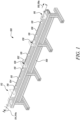
- Figure 1 illustrates a schematic perspective view of a system 100 for measuring loading on a test specimen 102.
- the system 100 is a split-Hopkinson bar (SHPB) apparatus that enables a high strain rate application of combined torsional loading and axial loading on the test specimen 102.
- SHPB split-Hopkinson bar
- the system 100 may be used for measuring torsional loading combined with axial loading on the test specimen 102.
- the system 100 may be used to obtain a mechanical response of a material under high strain rate deformation.
- the strain rates may be between approx. 100 s -1 and 10,000 s -1 .
- a material model may then be built based on the mechanical response of the material.
- the system 100 includes a first loading bar 104 and a second loading bar 106 arranged along a longitudinal axis A-A'.
- the longitudinal axis A-A' may extend along a longitudinal direction of the system 100.
- the first loading bar 104 and the second loading bar 106 are arranged in a straight line along the longitudinal axis A-A'.
- the test specimen 102 is arranged between the first and second loading bars 104, 106 along the longitudinal axis A-A'.
- a stress wave compression, tension, or torsion
- compression, tension, or torsion may be introduced into one of the first loading bar 104 and the second loading bar 106, which transmits the stress wave to the test specimen 102. This causes the test specimen 102 to deform.
- a change in impedance between the first and second loading bars 104, 106 and the test specimen 102 causes a portion of the stress wave to be reflected, and the rest to be transmitted into a subsequent rod.
- a stress-strain response of the test specimen 102 can be inferred.
- the first and second loading bars 104, 106 may be solid cylindrical bars. In alternative embodiments, the first and second loading bars 104, 106 may have a non-circular cross-section, for example, polygonal, elliptical, or oval. A size of each of the first and second loading bars 104, 106 may be selected based on various factors, such as a duration of an event during testing and a size of the test specimen 102. In some embodiments, a length of the first loading bar 104 may be different from a length of the second loading bar 106.
- the first and second loading bars 104, 106 may be constructed from any suitable material, such as, for example, metal or metal alloys (e.g., titanium alloy, high strength steel, phosphor bronze, etc.), plastic, elastomer, or composite material.
- the first and second loading bars 104, 106 are made of same material and include same cross-sectional area.
- the first and second loading bars 104, 106 may be elastic.
- the system 100 further includes a first loading unit 112 coupled to the first loading bar 104 and configured to apply a first load 114 to the first loading bar 104.
- the first loading unit 112 may be coupled to the first loading bar 104 though any suitable coupling mechanisms.
- the first loading unit 112 is arranged to apply the first load 114 at an end of the first loading bar 104 opposite to the end where the test specimen 102 is secured.
- the first loading unit 112 is further configured to apply a static torque 114a on the first loading bar 104, such that the first load 114 is the static torque 114a.
- the first loading unit 112 may include a torque pump configured to apply the first load 114 on the first loading bar 104.
- impact devices may also be used to apply the first load 114.
- the system 100 further includes a second loading unit 116 coupled to the second loading bar 106 and configured to apply a second load 118 to the second loading bar 106.
- the second loading unit 116 may be arranged to apply the second load 118 at an end of the second loading bar 106 opposite to the end where the test specimen 102 is secured.
- the second loading unit 116 is further configured to apply a static axial force 118a on the second loading bar 106, such that the second load 118 is the static axial force 118a.
- the first loading unit 112 and the second loading unit 116 may be controlled independently to apply the first load 114 and the second load 118, respectively.
- the second loading unit 116 may include either energy storage (e.g., by holding a bar in tension) or impact devices configured to apply the second load 118 or the static axial force 118a on the second loading bar 106.
- the first loading unit 112 and the second loading unit 116 may be configured to apply the first load 114 and the second load 118 on either the first loading bar 104 or the second loading bar 106.
- the first and second loading units 112, 116 may be mounted on one side of the SHPB only.
- the first and second loading units 112, 116 are mounted on a frame 108.
- the frame 108 may provide structural support to the system 100.
- the first and second loading bars 104, 106 may be coupled to the frame 108 through one or more supporting members 110.
- the first and second loading bars 104, 106 may pass through the one or more supporting members 110 for support.
- each supporting member 110 may allow movement of the first and second loading bars 104, 106 therethrough.
- the one or more supporting members 110 may be low friction supports that allow near frictionless movement of the first and second loading bars 104, 106 through the one or more supporting members 110.
- the system 100 may include any number of supporting members 110.
- the shape and configuration of the one or more supporting members 110 may vary based on a geometric shape and design of the first and second loading bars 104, 106. Additionally, some of the supporting members 110 may be different from the other supporting members 110.
- the relative positioning of the one or more supporting members 110 may be selected based on the length of the first and second loading bars 104, 106. Further, the one or more supporting members 110 may be movable along the longitudinal axis A-A' with respect to the frame 108.
- the system 100 further includes a first clamp 120 disposed between the first loading unit 112 and the test specimen 102 along the longitudinal axis A-A'.
- the first clamp 120 is configured to hold the first loading bar 104 against the first load 114.
- the first clamp 120 may be arranged and secured to the frame 108 at a location between the first loading unit 112 and the test specimen 102.
- the first clamp 120 may hold the first loading bar 104 such that when the first loading unit 112 applies the first load 114 to the first loading bar 104, the first load 114 is not transferred to the test specimen 102.
- a clamping force applied by the first clamp 120 may be sufficient to hold the first loading bar 104 against the first load 114.
- the first clamp 120 is configured to hold the first loading bar 104 in torsion.
- the system 100 further includes a second clamp 130 (shown partially) disposed between the second loading unit 116 and the test specimen 102 along the longitudinal axis A-A'.
- the second clamp 130 is configured to hold the second loading bar 106 against the second load 118.
- the second clamp 130 may be arranged and secured to the frame 108 at a location between the second loading unit 116 and the test specimen 102.
- the second clamp 130 may hold the second loading bar 106 such that when the second load unit 116 applies the second load 118 to the second loading bar 106, the second load 118 is not transferred to the test specimen 102.
- a clamping force applied by the second clamp 130 may be sufficient to hold the second loading bar 106 against the second load 118.
- the second clamp 130 is configured to hold the second loading bar 106 in tension.
- the second clamp 130 may be similar to the first clamp 120.
- Figure 2 illustrates an enlarged schematic perspective view of the system 100.
- the first load 114 or the static torque 114a may be stored by means of the first clamp 120 holding the first loading bar 104 until the first load 114 or the static torque 114a needs to be released.
- a stress-wave can be introduced into the first loading bar 104 by rapid release of the first load 114 or the static torque 114a stored with the first clamp 120 remote from the test specimen 102.
- the system 100 further includes a clamp actuating unit 140 configured to selectively release at least the first clamp 120.
- the second load 118 or the static axial force 118a can be stored by means of the second clamp 130 holding the second loading bar 106 until the second load 118 or the static axial force 118a needs to be released.
- a stress-wave can be introduced into the second loading bar 106 by rapid release of the second load 118 or the static axial force 118a stored with the second clamp 130 remote from the test specimen 102.
- the clamp actuating unit 140 is further configured to selectively release the second clamp 130. Specifically, the clamp actuating unit 140 is configured to release the first clamp 120 and the second clamp 130.
- one or more strain gauges 128 are suitably positioned on the first loading bar 104 and the second loading bar 106. In some embodiments, the one or more strain gauges 128 may measure shear and axial strains in the first and second loading bars 104, 106. In some embodiments, the one or more strain gauges 128 may be fixed to a surface of the first and second loading bars 104, 106. In some embodiments, the strains in the first and second loading bars 104, 106 may be determined from a surface velocity of the first and second loading bars 104, 106 measured using Photon Doppler Velocimetry (PDV) or Laser Doppler Velocimetry (LDV). In some embodiments, measurement of a deformation of the test specimen 102 may also be made using lasers, high speed photography or strain gauges. Measurements of force at a bar-specimen interface may be made using stress gauges.
- PDV Photon Doppler Velocimetry
- LDV Laser Doppler Velocimetry
- Figure 3 illustrates an enlarged schematic side view of the system 100 of Figure 2 .
- the first loading bar 104 Upon release of the first clamp 120, the first loading bar 104 is configured to apply a first loading wave 122 to the test specimen 102 in response to the first load 114.
- the first loading wave 122 may reach the test specimen 102.
- the first loading wave 122 is a torsion wave 124.
- the second loading bar 106 Upon release of the second clamp 130, the second loading bar 106 is configured to apply a second loading wave 132 to the test specimen 102 in response to the second load 118. Therefore, upon release of the second clamp 130, the second loading wave 132 may reach the test specimen 102.
- the second loading wave 132 is an axial wave 134.
- the clamp actuating unit 140 may independently control the first clamp 120 and the second clamp 130 for applying the first loading wave 122 and the second loading wave 132 to the test specimen 102, respectively.
- the clamp actuating unit 140 may be configured to release the first and second clamps 120, 130 simultaneously.
- the first and second clamps 120, 130 may be suitably positioned along the longitudinal axis A-A' such that the first and second loading waves 122, 132 may arrive at the test specimen 102 simultaneously. Since first loading wave 122 (e.g., torsion wave 124) may travel slower than the second loading wave 132 (e.g., axial wave 134), the second clamp 130 may be positioned further from the test specimen 102 that the first clamp 120.
- a distance between each of the first and second clamps 120, 130 and the test specimen 102 may be chosen so as to control a timing of arrival of the first and second loading waves 122, 132 at the test specimen 102.
- a position of the first and second clamps 120, 130 along the longitudinal axis A-A' may be determined previously based on calculations and experimental data.
- the clamp actuating unit 140 may be configured to release the first and second clamps 120, 130 in a timely sequential manner.
- the clamp actuating unit 140 may release the second clamp 130 after releasing the first clamp 120 with a predetermined time delay.
- the first and second clamps 120, 130 may be positioned at equal distance from the test specimen 102.
- a time of releasing of the first clamp 120 and a time of releasing of the second clamp 116 may be determined previously based on calculations and experimental data to allow the first and second loading waves 122, 132 to reach the test specimen 102 simultaneously.
- the positions of the first and second clamps 120, 130 and the times of releasing of the first and second clamps 120, 130 may both be controlled to allow the first and second loading waves 122, 132 to reach the test specimen 102 simultaneously. In some other embodiments, the positions and/or the times of releasing of the first and second clamps 120, 130 may be chosen such that the first and second loading waves 122, 132 arrive at the test specimen 102 at different points in time.
- the respective distances of the first and second clamps 120, 130 from the test specimen 102 may be chosen.
- the system 100 is used for measuring combined torsional and tensile loading on the test specimen 102.
- the system 100 may also be adapted for measuring combined torsional and compression loading on the test specimen 102.
- the second loading unit 116 may be configured to apply a compression load on the test specimen 102.
- a compression stress-wave may be introduced into the second loading bar 106 by the second loading unit 116.
- the second loading unit 116 may include a striker bar, impacted into the second loading bar 106 by, for example, a gas gun.
- the second clamp 130 may be configured to hold the second loading bar 106 in compression.
- first and second loading units 112, 116 are both axial force systems (i.e., arranged to apply a static axial force to the first and second respective loading bars 104, 106), or are both torsional force systems (i.e., arranged to apply a static torque to the first and second respective loading bars 104, 106).
- first and second loading units 112, 116 are both axial force systems
- one loading unit may provide a tension force and the other may provide a compression force, or both loading units may provide the same type of force (i.e., tension or compression).
- the directions of the torsional forces may be same or opposite to each other.
- Figure 4 illustrates a schematic perspective view of the clamp actuating unit 140 and the first clamp 120.
- An outer housing of the clamp actuating unit 140 may be omitted in Figure 4 for the purpose of illustration.
- the clamp actuating unit 140 includes at least one first electromechanical transducer 142 switchable between a retained state P1 (shown in Figure 5A ) and a released state P2 (shown in Figure 5B ).
- the at least one first electromechanical transducer 142 may be any type of electromechanical transducer operable to convert electrical energy to mechanical energy (e.g., a piezoelectric device).
- the at least one first electromechanical transducer 142 includes a pair of first electromechanical transducers 142a, 142b such that both the first electromechanical transducers 142a, 142b are switchable between the retained state P1 and the released state P2.
- the first clamp 120 includes a pair of first clamping members 126a, 126b configured to hold the first loading bar 104 therebetween.
- each first electromechanical transducer 142a, 142b is configured to load a corresponding first clamping member 126a, 126b from the pair of first clamping members 126a, 126b to hold the first loading bar 104 therebetween.
- the first electromechanical transducer 142a is configured to load the first clamping member 126a
- the first electromechanical transducer 142b is configured to load the first clamping member 126b to hold the first loading bar 104 between the pair of first clamping members 126a, 126b.
- the at least one first electromechanical transducer 142 includes at least one first piezoelectric element 144 configured to expand along a first transverse axis B-B' inclined to the longitudinal axis A-A' upon application of a first electrical signal S1.
- the at least one first piezoelectric element 144 includes a pair of first piezoelectric elements 144a, 144b. The pair of first piezoelectric elements 144a, 144b are enclosed within a corresponding first housing 143a, 143b.
- the clamp actuating unit 140 further includes a controller 150 configured to electrically actuate the at least one first electromechanical transducer 142.
- the controller 150 may be embodied in a number of different ways.
- the controller 150 may be embodied as various processing means, such as one or more of a microprocessor or other processing elements, a coprocessor, or various other computing or processing devices including integrated circuits, such as, for example, an ASIC (application specific integrated circuit), or the like.
- the controller 150 may be configured to execute instructions stored in a memory provided with the controller 150 or otherwise accessible to the controller 150.
- the controller 150 may represent an entity (e.g., physically embodied in circuitry - in the form of processing circuitry) capable of performing operations according to some embodiments while configured accordingly.
- the controller 150 may have specifically configured hardware for conducting the operations described herein.
- the controller 150 when the controller 150 is embodied as an executor of software instructions, the instructions may specifically configure the controller 150 to perform the operations described herein.
- the controller 150 is electrically coupled to the at least one first electromechanical transducer 142 (or the at least one first piezoelectric element 144). In some embodiments, the controller 150 is configured to provide one or more electrical signals to the at least one first electromechanical transducer 142 (or the at least one first piezoelectric element 144). In some examples, the one or more electrical signals may be in the form of a positive voltage applied across the at least one first piezoelectric element 144.
- the controller 150 provides the first electrical signal S1 to each of the first piezoelectric elements 144a, 144b.
- the first piezoelectric elements 144a, 144b may expand along the first transverse axis B-B'.
- the first electromechanical transducers 142a, 142b (or the first piezoelectric elements 144a, 144b) are configured to expand along the first transverse axis B-B' to load the corresponding first clamping members 126a, 126b upon application of the first electrical signal S1 by the controller 150.
- the at least one first piezoelectric element 144 may further be configured to contract along the first transverse axis B-B' upon removal of the first electrical signal S1.
- the first transverse axis B-B' is orthogonal to the longitudinal axis A-A'. In some other embodiments, the first transverse axis B-B' is inclined at an oblique angle with respect to the longitudinal axis A-A'.
- the clamp actuating unit 140 further includes a first actuator 146 configured to apply a first clamping force F1 on the at least one first electromechanical transducer 142.
- the clamp actuating unit 140 includes a pair of first actuators 146a, 146b configured to apply the first clamping force F1 on the corresponding first electromechanical transducer 142a, 142b.
- the first actuator 146a is configured to apply the first clamping force F1 on the first electromechanical transducer 142a
- the first actuator 146b is configured to apply the first clamping force F1 on the first electromechanical transducer 142b.
- the first actuators 146a, 146b may include a hydraulic ram configured to receive a hydraulic pressure from a suitable pressure source (not shown) though corresponding inlets 147a, 147b.
- the first actuators 146a, 146b may be supported along the first transverse axis B-B' by a frame 149 of the clamp actuating unit 140 such that the first clamping force F1 applied by the first actuators 146a, 146b is along the first transverse axis B-B'.
- the clamp actuating unit 140 further includes at least one first support member 148 to support the at least one first electromechanical transducer 142 between the first clamp 120 and the first actuator 146.
- the at least one first support member 148 is configured to receive the at least one first electromechanical transducer 142 through the at least one first support member 148.
- the at least one first support member 148 supports the at least one first electromechanical transducer 142 such that the first support member 148 allows the first electromechanical transducer 142 (or the first piezoelectric element 144) to expand or contract along the first transverse axis B-B'.
- the clamp actuating unit 140 includes a pair of first support members 148a, 148b corresponding to the pair of first electromechanical transducers 142a, 142b.
- the first support member 148a is configured to receive the first electromechanical transducers 142a through the at least one first support member 148a
- the first support member 148b is configured to receive the first electromechanical transducers 142b through the at least one first support member 148b.
- Figures 5A and 5B illustrate schematic side views of the clamp actuating unit 140 and the first clamp 120 in the retained state P1 and the released state P2 of the first electromechanical transducer 142, respectively.
- the at least one first electromechanical transducer 142 is configured to load the first clamp 120, such that the first clamp 120 holds the first loading bar 104 against the first load 114.
- the first electromechanical transducer 142a is configured to load the first clamping member 126a
- the first electromechanical transducer 142b is configured to load the first clamping member 126b such that the first clamping members 126a, 126b hold the first loading bar 104 therebetween.
- the at least one first piezoelectric element 144 expands to load the first clamp 120.
- Figure 5A illustrates the at least one first piezoelectric element 144 in an expanded state of the at least one first piezoelectric element 144.
- the at least one first piezoelectric element 144 has a length L1 in the expanded state.
- the first piezoelectric element 144a expands along the first transverse axis B-B' to load the first clamping member 126a
- the first piezoelectric element 144b expands along the first transverse axis B-B' to load the first clamping member 126b.
- the controller 150 is further configured to apply the first electrical signal S1 to the at least one first piezoelectric element 144 to switch the at least one first piezoelectric element 144 to the retained state P1.
- each of the first piezoelectric elements 144a, 144b may expand along the first transverse axis B-B' when the first electrical signal S1 is applied to the first piezoelectric elements 144a, 144b.
- the at least one first electromechanical transducer 142 in the retained state P1, is configured to at least partially transmit the first clamping force F1 received from the first actuator 146 to the first clamp 120.
- the first electromechanical transducer 142a is configured to at least partially transmit the first clamping force F1 received from the first actuator 146a to the first clamping member 126a.
- the first electromechanical transducer 142b is configured to at least partially transmit the first clamping force F1 received from the first actuator 146b to the first clamping member 126b.
- the loads applied by the first electromechanical transducers 142a, 142b based on the expansion of the first piezoelectric elements 144a, 144b, and the first clamping force F1 are configured to hold the first loading bar 104 against the first load 114.
- the at least one first electromechanical transducer 142 is configured to release the first clamp 120.
- the controller 150 is configured to electrically actuate the at least one first electromechanical transducer 142 from the retained state P1 to the released state P2 to release the first clamp 120.
- the at least one first piezoelectric element 144 contracts to release the first clamp 120.
- Figure 5B illustrates the at least one first piezoelectric element 144 in a contracted state of the at least one first piezoelectric element 144.
- the at least one first piezoelectric element 144 has a length L2 in the contracted state such that the length L2 is smaller than the length L1 (i.e., L2 ⁇ L1).
- the first piezoelectric elements 144a, 144b contract along the first transverse axis B-B' to release the first clamp 120.
- the controller 150 is further configured to remove the first electrical signal S1 from the at least one first piezoelectric element 144 to switch the at least one first piezoelectric element 144 to the released state P2.
- the controller 150 is further configured to remove the first electrical signal S1 from the first piezoelectric elements 144a, 144b to switch the first piezoelectric elements 144a, 144b to the released state P2.
- each of the first piezoelectric elements 144a, 144b may resume initial shape when the first electrical signal S1 is removed from the first piezoelectric elements 144a, 144b.
- a movement of the first clamping members 126a, 126b and the contraction of the first piezoelectric elements 144a, 144b are shown magnified for the purpose of illustration, and the actual movement of the first clamping members 126a, 126b and the contraction of the first piezoelectric elements 144a, 144b may vary based on actual usage requirements.
- the at least one first electromechanical transducer 142 in the released state P2, is configured to remove the first clamping force F1 from the first clamp 120.
- the first electromechanical transducers 142a, 142b are configured to remove the first clamping force F1 from the first clamping members 126a, 126b.
- the controller 150 is configured to electrically actuate the at least one first electromechanical transducer 142 from the retained state P1 to the released state P2 to release the first clamp 120, such that the first loading bar 104 applies the first loading wave 122 (shown in Figure 3 ) to the test specimen 102.
- Figure 6 illustrates a schematic perspective view of the clamp actuating unit 140 and the second clamp 130.
- An outer housing of the clamp actuating unit 140 is omitted in Figure 6 for the purpose of illustration.
- the clamp actuating unit 140 further includes at least one second electromechanical transducer 152 switchable between a retained state Q1 (shown in Figure 7A ) and a released state Q2 (shown in Figure 7B ).
- the at least one second electromechanical transducer 152 may be any type of electromechanical transducer operable to convert electrical energy to mechanical energy (e.g., a piezoelectric device).
- the at least one second electromechanical transducer 152 includes a pair of second electromechanical transducers 152a, 152b such that both the second electromechanical transducers 152a, 152b are switchable between the retained state Q1 and the released state Q2.
- the at least one second electromechanical transducers 152 may be similar to the at least one first electromechanical transducer 142.
- the second clamp 130 includes a pair of second clamping members 162a, 162b configured to hold the second loading bar 106 therebetween.
- each second electromechanical transducer 152a, 152b is configured to load a corresponding second clamping member 162a, 162b from the pair of second clamping members 162a, 162b to hold the second loading bar 106 therebetween.
- the second electromechanical transducer 152a is configured to load the second clamping member 162a
- the second electromechanical transducer 152b is configured to load the second clamping member 162b to hold the second loading bar 106 between the pair of second clamping members 162a, 162b.
- the at least one second electromechanical transducer 152 includes at least one second piezoelectric element 154 configured to expand along a second transverse axis C-C' inclined to the longitudinal axis A-A' upon application of a second electrical signal S2.
- the at least one second piezoelectric element 154 includes a pair of second piezoelectric elements 154a, 154b. The pair of second piezoelectric elements 154a, 154b are enclosed within a corresponding second housing 153a, 153b.
- the clamp actuating unit 140 further includes the controller 150 configured to electrically actuate the at least one second electromechanical transducer 152.
- the controller 150 may provide the second electrical signal S2 to each of the second piezoelectric elements 154a, 154b.
- the second piezoelectric elements 154a, 154b may expand along the second transverse axis C-C'.
- the second electromechanical transducers 152a, 152b (or the second piezoelectric elements 154a, 154b) are configured to expand along the second transverse axis C-C' to load the corresponding second clamping members 162a, 162b upon application of the second electrical signal S2 by the controller 150.
- the at least one second piezoelectric element 154 may further be configured to contract along the second transverse axis C-C' upon removal of the second electrical signal S2.
- the second transverse axis C-C' is orthogonal to the longitudinal axis A-A'. In some other embodiments, the second transverse axis C-C' is inclined at an oblique angle with respect to the longitudinal axis A-A'. In some embodiments, the second transverse axis C-C' may be parallel to the first transverse axis B-B' (shown in Figure 4 ).
- the clamp actuating unit 140 further includes a second actuator 156 configured to apply a second clamping force F2 on the at least one second electromechanical transducer 152.
- the clamp actuating unit 140 includes a pair of second actuators 156a, 156b configured to apply the second clamping force F2 on the corresponding second electromechanical transducers 152a, 152b.
- the second actuator 156a is configured to apply the second clamping force F2 on the second electromechanical transducer 152a
- the second actuator 156b is configured to apply the second clamping force F2 on the second electromechanical transducer 152b.
- the at least one second actuator 156 may include a hydraulic ram configured to receive a hydraulic pressure from a suitable pressure source (not shown) though a corresponding inlet 157a, 157b.
- the second actuators 156a, 156b may be supported along the second transverse axis C-C' by a frame 159 of the clamp actuating unit 140 such that the second clamping force F2 applied by the second actuators 156a, 156b is along the second transverse axis C-C'.
- the clamp actuating unit 140 further includes at least one second support member 158 to support the at least one second electromechanical transducer 152 between the second clamp 130 and the second actuator 156.
- the at least one second support member 158 is configured to receive the at least one second electromechanical transducer 152 through the at least one second support member 158.
- the at least one second support member 158 supports the at least one second electromechanical transducer 152 such that the second support member 158 allows the second electromechanical transducer 152 (or the second piezoelectric element 154) to expand or contract along the second transverse axis C-C'.
- the clamp actuating unit 140 includes a pair of second support members 158a, 158b corresponding to the pair of second electromechanical transducers 152a, 152b.
- the second support members 158a is configured to receive the second electromechanical transducer 152a through the at least one second support member 158a
- the second support member 158b is configured to receive the second electromechanical transducers 152b through the at least one second support member 158b.
- FIGs 7A and 7B illustrate schematic side views of the clamp actuating unit 140 and the second clamp 130 in the retained state Q1 and the released state Q2 of the second electromechanical transducer 152, respectively.
- the at least one second electromechanical transducer 152 is configured to load the second clamp 130, such that the second clamp 130 holds the second loading bar 106 against the second load 118.
- the second electromechanical transducer 152a is configured to load the second clamping member 162a
- the second electromechanical transducer 152b is configured to load the second clamping member 162b such that the second clamping members 162a, 162b hold the second loading bar 106 therebetween.
- the at least one second piezoelectric element 154 expands to load the second clamp 130.
- Figure 7A illustrates the at least one second piezoelectric element 154 in an expanded state of the at least one second piezoelectric element 154.
- the at least one second piezoelectric element 154 has a length M1 in the expanded state.
- the second piezoelectric element 154a expands along the second transverse axis C-C' to load the second clamping member 162a
- the second piezoelectric element 154b expands along the second transverse axis C-C' to load the second clamping member 162b.
- the controller 150 is further configured to apply the second electrical signal S2 to the at least one second piezoelectric element 154 to switch the at least one second piezoelectric element 154 to the retained state Q1.
- each of the second piezoelectric elements 154a, 154b may expand along the second transverse axis C-C' when the second electrical signal S2 is applied to the second piezoelectric elements 154a, 154b.
- the at least one second electromechanical transducer 152 in the retained state Q1, is configured to at least partially transmit the second clamping force F2 received from the second actuator 156 to the second clamp 130.
- the second electromechanical transducer 152a is configured to at least partially transmit the second clamping force F2 received from the second actuator 156a to the second clamping member 162a.
- the second electromechanical transducer 152b is configured to at least partially transmit the second clamping force F2 received from the second actuator 156b to the second clamping member 162b.
- the loads applied by the second electromechanical transducers 152a, 152b based on the expansion of the second piezoelectric elements 154a, 154b, and the second clamping force F2 are configured to hold the second loading bar 106 against the second load 118.
- the at least one second electromechanical transducer 152 is configured to release the second clamp 130.
- the controller 150 is configured to electrically actuate the at least one second electromechanical transducer 152 from the retained state Q1 to the released state Q2 to release the second clamp 130.
- the at least one second piezoelectric element 154 contracts to release the second clamp 130.
- Figure 7B illustrates the at least one second piezoelectric element 154 in a contracted state of the at least one second piezoelectric element 154.
- the at least one second piezoelectric element 154 has a length M2 in the contracted state such that the length M2 is smaller than the length M1 (i.e., M2 ⁇ M1).
- the second piezoelectric elements 154a, 154b contract along the second transverse axis C-C' to release the second clamp 130.
- the controller 150 is further configured to remove the second electrical signal S2 from the at least one second piezoelectric element 154 to switch the at least one second piezoelectric element 154 to the released state Q2. In some embodiments, the controller 150 is further configured to remove the second electrical signal S2 from the second piezoelectric elements 154a, 154b to switch the second piezoelectric elements 154a, 154b to the released state Q2. Specifically, each of the second piezoelectric elements 154a, 154b may resume initial shape when the second electrical signal S2 is removed from the second piezoelectric elements 154a, 154b.
- a movement of the second clamping members 162a, 162b and the contraction of the second piezoelectric elements 152a, 152b are shown magnified for the purpose of illustration, and the actual movement of the second clamping members 162a, 162b and the contraction of the second piezoelectric elements 152a, 152b may vary based on actual usage requirements.
- the at least one second electromechanical transducer 152 in the released state Q2, is configured to remove the second clamping force F2 from the second clamp 130.
- the second electromechanical transducers 152a, 152b are configured to remove the second clamping force F2 from the second clamping members 162a, 162b.
- the controller 150 is configured to electrically actuate the at least one second electromechanical transducer 152 from the retained state Q1 to the released state Q2 to release the second clamp 130, such that the second loading bar 106 applies the second loading wave 132 (shown in Figure 3 ) to the test specimen 102.
- the first loading unit 112 when measuring loading on the test specimen 102, is configured to apply the first load 114 (e.g., the static torque 114a) on the first loading bar 104.
- the first clamp 120 is configured to hold the first loading bar 104 against the first load 114 as the at least one first electromechanical transducer 142 is in the retained state P1.
- the controller 150 is configured to apply the first electrical signal S1 to the at least one first piezoelectric element 144 (or the at least one first electromechanical transducer 142) such that the at least one first piezoelectric element 144 expands along the first transverse axis B-B' to load the first clamp 120, and thus, hold the first loading bar 104.
- the at least one first electromechanical transducer 142 is configured to at least partially transmit the first clamping force F1 received from the first actuator 146 to the first clamp 120.
- the second loading unit 116 is configured to apply the second load 118 (e.g., the static axial force 118a) on the second loading bar 106.
- the second clamp 130 is configured to hold the second loading bar 106 against the second load 118 as the at least one second electromechanical transducer 152 is in the retained state Q1.
- the controller 150 is configured to apply the second electrical signal S2 to the at least one second piezoelectric element 154 (or the at least one second electromechanical transducer 152) such that the at least one second piezoelectric element 154 expands along the second transverse axis C-C' to load the second clamp 130, and thus, hold the second loading bar 106.
- the at least one second electromechanical transducer 152 is configured to at least partially transmit the second clamping force F2 received from the second actuator 156 to the second clamp 130.
- the controller 150 is configured to remove the first electrical signal S1 from the at least one first piezoelectric element 144 (or the at least one first electromechanical transducer 142) to switch the at least one first piezoelectric element 144 to the released state P2.
- the at least one first piezoelectric element 144 contracts along the first transverse axis B-B' to release the first clamp 120 such that the first loading bar 104 applies the first loading wave 122 to the test specimen 102.
- the controller 150 is configured to remove the second electrical signal S2 from the at least one second piezoelectric element 154 (or the at least one second electromechanical transducer 152) to switch the at least one second piezoelectric element 154 to the released state Q2.
- the at least one second piezoelectric element 154 contracts along the second transverse axis C-C' to release the second clamp 130 such that the second loading bar 106 applies the second loading wave 132 to the test specimen 102. Loading on the test specimen 102 is initiated by releasing the first and second clamps 120, 130 at predetermined times.
- first electromechanical transducer 142 and the at least one second electromechanical transducer 152 may allow the clamp actuating unit 140 to precisely and accurately control release times of the first clamp 120 and the second clamp 130, respectively. This may help in controlling application of the first loading wave 122 and the second loading wave 132 on the test specimen 102 accurately. Further, first clamp 120 and second clamp 130 may be released quickly and reliably as compared to conventional clamps with mechanical fuse.
- one of the first clamp 120 and the second clamp 130 may be loaded using a mechanical fuse (instead of electromechanical transducer) while the other may be loaded using the electromechanical transducer.
- a release of the clamp loaded with the mechanical fuse may be configured to trigger a release of the clamp loaded with the electromechanical transducer to control the application of corresponding stress waves.
- Figure 8 illustrates a flow chart describing a method 170 for measuring loading on the test specimen 102.
- the method 170 may be implemented using the system 100 of Figures 1-7B incorporating the teachings of the present invention.
- the method 170 includes arranging the test specimen 102 between the first loading bar 104 and the second loading bar 106.
- the first and second loading bars 104, 106 are arranged along the longitudinal axis A-A'.
- the method 170 further includes holding, via the first clamp 120, the first loading bar 104 against the first load 114. Upon release of the first clamp 120, the first loading bar 104 is configured to apply the first loading wave 122 to the test specimen 102 in response to the first load 114.
- the method 170 further includes electrically actuating, via the controller 150, the at least one first electromechanical transducer 142 to the retained state P1. In the retained state P1, the at least one first electromechanical transducer 142 loads the first clamp 120, such that the first clamp 120 holds the first loading bar 104.
- electrically actuating the at least one first electromechanical transducer 142 to the retained state P1 further includes applying the first electrical signal S1 to the at least one first electromechanical transducer 142, such that the at least one first electromechanical transducer 142 expands along the first transverse axis B-B' inclined to the longitudinal axis A-A' to load the first clamp 120.
- the method 170 further includes applying, via the first actuator 146, the first clamping force F1 on the at least one first electromechanical transducer 142.
- the at least one first electromechanical transducer 142 is configured to at least partially transmit the first clamping force F1 received from the first actuator 146 to the first clamp 120.
- the method 170 further includes applying, via the first loading unit 112, the first load 114 to the first loading bar 104.
- the method 170 further includes holding, via the second clamp 130, the second loading bar 106 against the second load 118. Upon release of the second clamp 130, the second loading bar 106 is configured to apply the second loading wave 132 to the test specimen 102 in response to the second load 118.
- the method 170 further includes electrically actuating, via the controller 150, the at least one second electromechanical transducer 152 to the retained state Q1.
- the at least one second electromechanical transducer 152 loads the second clamp 130, such that the second clamp 130 holds the second loading bar 106.
- electrically actuating the at least one second electromechanical transducer 152 to the retained state Q1 further includes applying the second electrical signal S2 to the at least one second electromechanical transducer 152, such that the at least one second electromechanical transducer 152 expands along the second transverse axis C-C' inclined to the longitudinal axis A-A' to load the second clamp 130.
- the method 170 further includes applying, via the second actuator 156, the second clamping force F2 on the at least one second electromechanical transducer 152.
- the at least one second electromechanical transducer 152 is configured to at least partially transmit the second clamping force F2 received from the second actuator 156 to the second clamp 130.
- the method 170 further includes applying, via the second loading unit 116, the second load 118 to the second loading bar 106.
- the method 170 further includes electrically actuating, via the controller 150, the at least one first electromechanical transducer 142 from the retained state P1 to the released state P2.
- the at least one first electromechanical transducer 142 releases the first clamp 120, such that the first loading bar 104 applies the first loading wave 122 to the test specimen 102.
- electrically actuating the at least one first electromechanical transducer 142 from the retained state P1 to the released state P2 further includes removing the first electrical signal S1 from the at least one first electromechanical transducer 142, such that the at least one first electromechanical transducer 142 contracts along the first transverse axis B-B' to release the first clamp 120.
- the method 170 further includes electrically actuating, via the controller 150, the at least one second electromechanical transducer 152 from the retained state Q1 to the released state Q2. In the released state Q2, the at least one second electromechanical transducer 152 releases the second clamp 130, such that the second loading bar 106 applies the second loading wave 132 to the test specimen 102.
- electrically actuating the at least one second electromechanical transducer 152 from the retained state Q1 to the released state Q2 further includes removing the second electrical signal S2 from the at least one second electromechanical transducer 152, such that the at least one second electromechanical transducer 152 contracts along the second transverse axis C-C' to release the second clamp 130.
- the method 170 further includes simultaneously or timely sequentially releasing the first clamp 120 and the second clamp 130.
Landscapes
- Physics & Mathematics (AREA)
- Health & Medical Sciences (AREA)
- Life Sciences & Earth Sciences (AREA)
- Chemical & Material Sciences (AREA)
- Analytical Chemistry (AREA)
- Biochemistry (AREA)
- General Health & Medical Sciences (AREA)
- General Physics & Mathematics (AREA)
- Immunology (AREA)
- Pathology (AREA)
- Investigating Strength Of Materials By Application Of Mechanical Stress (AREA)
Abstract
Description
- The present invention relates to a system and a method for applying dynamic loading to a test specimen.
- Engineering applications may require data on dynamic mechanical response of materials under high strain rate deformation. The split Hopkinson Pressure Bar (SHPB), also referred to as the Kolsky Bar, is a commonly used setup for testing materials at high strain rates. A specimen is sandwiched between two rods, each of which is instrumented with strain gauges. A stress wave, compression, tension, or torsion, is introduced into one of the rods (an input bar), which transmits the stress wave to the specimen. This causes the specimen to deform. A change in impedance between the rods and the specimen causes some of the stress wave to be reflected, and the rest to be transmitted (into an output rod). By measuring these three stress waves (incident, reflected and transmitted), a stress-strain response of the specimen can be inferred.
- Known arrangements of SHPB for carrying out tests may allow testing in uniaxial stress in tension or in compression, and in pure shear. Some arrangements may also allow combined loading of torsion and tension/compression on the specimen. In such arrangements, torsion loading and tension/compression loading can be applied on separate rods on either end of SHPB or a single rod. Conventional SHPBs often utilize clamps to hold the rods under torsion, tension and/or compression until the load is to be released. As the clamps are released, the stress waves travel along the rods and are applied to the specimen. Multiple clamps may be utilized with SHPB based on arrangement of loading on the specimen.
- Conventional clamps may typically include a mechanical fuse (e.g., a notched pin) which fractures to release the clamps. A release time of such mechanical clamp may not be controlled precisely and accurately by virtue of fracturing of the mechanical fuse. This may be problematic to the operation of SHPB since precise control of clamps is required to ensure that the arrival of the stress waves at the specimen is correctly synchronised in a combined loading arrangement. Further, the release time of mechanical clamps may not be accurately synchronized with the release time of other clamps if multiple clamps are utilized with SHPB.
- The present invention provides a system for measuring loading on a test specimen, and a method for measuring loading on a test specimen, as set out in the appended claims.
- The system includes a first loading bar and a second loading bar arranged along a longitudinal axis. The test specimen is arranged between the first and second loading bars along the longitudinal axis. The system further includes a first loading unit coupled to the first loading bar and configured to apply a first load to the first loading bar. The system further includes a second loading unit coupled to the second loading bar and configured to apply a second load to the second loading bar. The system further includes a first clamp disposed between the first loading unit and the test specimen along the longitudinal axis. The first clamp is configured to hold the first loading bar against the first load. Upon release of the first clamp, the first loading bar is configured to apply a first loading wave to the test specimen in response to the first load. The system further includes a second clamp disposed between the second loading unit and the test specimen along the longitudinal axis. The second clamp is configured to hold the second loading bar against the second load. Upon release of the second clamp, the second loading bar is configured to apply a second loading wave to the test specimen in response to the second load. The system further includes a clamp actuating unit configured to selectively release at least the first clamp. The clamp actuating unit includes at least one first electromechanical transducer switchable between a retained state and a released state. In the retained state, the at least one first electromechanical transducer is configured to load the first clamp, such that the first clamp holds the first loading bar against the first load. In the released state, the at least one first electromechanical transducer is configured to release the first clamp. The clamp actuating unit further includes a controller configured to electrically actuate the at least one first electromechanical transducer from the retained state to the released state to release the first clamp, such that the first loading bar applies the first loading wave to the test specimen.
- The skilled person will appreciate that except where mutually exclusive, a feature or parameter described in relation to any one of the above aspects may be applied to any other aspect. Furthermore, except where mutually exclusive, any feature or parameter described herein may be applied to any aspect and/or combined with any other feature or parameter described herein.
- Embodiments will now be described by way of example only, with reference to the Figures, in which:
-
Figure 1 is a schematic perspective view of a system for measuring loading on a test specimen, according to an embodiment of the present invention; -
Figure 2 is an enlarged schematic perspective view of the system ofFigure 1 , according to an embodiment of the present invention; -
Figure 3 is an enlarged schematic side view of the system ofFigure 1 , according to an embodiment of the present invention; -
Figure 4 is a schematic perspective view of a clamp actuating unit and a first clamp, according to an embodiment of the present invention; -
Figures 5A and 5B illustrate schematic side views of the clamp actuating unit and the first clamp ofFigure 4 in a retained state and a released state, respectively, of at least one first electromechanical transducer, according to an embodiment of the present invention; -
Figure 6 is a schematic perspective view of the clamp actuating unit and a second clamp, according to an embodiment of the present invention; -
Figures 7A and 7B illustrate schematic side views of the clamp actuating unit and the second clamp ofFigure 6 in a retained state and a released state, respectively, of at least one second electromechanical transducer, according to an embodiment of the present invention; and -
Figure 8 illustrates a flow chart of a method for measuring loading on a test specimen, according to another embodiment of the present invention. -
Figure 1 illustrates a schematic perspective view of asystem 100 for measuring loading on atest specimen 102. In some embodiments, thesystem 100 is a split-Hopkinson bar (SHPB) apparatus that enables a high strain rate application of combined torsional loading and axial loading on thetest specimen 102. In other words, thesystem 100 may be used for measuring torsional loading combined with axial loading on thetest specimen 102. In some embodiments, thesystem 100 may be used to obtain a mechanical response of a material under high strain rate deformation. In some embodiments, the strain rates may be between approx. 100 s-1 and 10,000 s-1. A material model may then be built based on the mechanical response of the material. - The
system 100 includes afirst loading bar 104 and asecond loading bar 106 arranged along a longitudinal axis A-A'. The longitudinal axis A-A' may extend along a longitudinal direction of thesystem 100. In some embodiments, thefirst loading bar 104 and thesecond loading bar 106 are arranged in a straight line along the longitudinal axis A-A'. Thetest specimen 102 is arranged between the first andsecond loading bars - A stress wave (compression, tension, or torsion) may be introduced into one of the
first loading bar 104 and thesecond loading bar 106, which transmits the stress wave to thetest specimen 102. This causes thetest specimen 102 to deform. A change in impedance between the first andsecond loading bars test specimen 102 causes a portion of the stress wave to be reflected, and the rest to be transmitted into a subsequent rod. By measuring the three stress waves (incident, transmitted, and reflected), a stress-strain response of thetest specimen 102 can be inferred. - In some embodiments, the first and
second loading bars second loading bars second loading bars test specimen 102. In some embodiments, a length of thefirst loading bar 104 may be different from a length of thesecond loading bar 106. In some embodiments, the first andsecond loading bars second loading bars - The
system 100 further includes afirst loading unit 112 coupled to thefirst loading bar 104 and configured to apply a first load 114 to thefirst loading bar 104. In some embodiments, thefirst loading unit 112 may be coupled to thefirst loading bar 104 though any suitable coupling mechanisms. In some embodiments, thefirst loading unit 112 is arranged to apply the first load 114 at an end of thefirst loading bar 104 opposite to the end where thetest specimen 102 is secured. In some embodiments, thefirst loading unit 112 is further configured to apply a static torque 114a on thefirst loading bar 104, such that the first load 114 is the static torque 114a. In some embodiments, thefirst loading unit 112 may include a torque pump configured to apply the first load 114 on thefirst loading bar 104. In some embodiments, impact devices may also be used to apply the first load 114. - The
system 100 further includes asecond loading unit 116 coupled to thesecond loading bar 106 and configured to apply a second load 118 to thesecond loading bar 106. In some embodiments, thesecond loading unit 116 may be arranged to apply the second load 118 at an end of thesecond loading bar 106 opposite to the end where thetest specimen 102 is secured. In some embodiments, thesecond loading unit 116 is further configured to apply a static axial force 118a on thesecond loading bar 106, such that the second load 118 is the static axial force 118a. In some embodiments, thefirst loading unit 112 and thesecond loading unit 116 may be controlled independently to apply the first load 114 and the second load 118, respectively. In some embodiments, thesecond loading unit 116 may include either energy storage (e.g., by holding a bar in tension) or impact devices configured to apply the second load 118 or the static axial force 118a on thesecond loading bar 106. - In some embodiments, the
first loading unit 112 and thesecond loading unit 116 may be configured to apply the first load 114 and the second load 118 on either thefirst loading bar 104 or thesecond loading bar 106. Thus, the first andsecond loading units - In some embodiments, the first and
second loading units frame 108. Theframe 108 may provide structural support to thesystem 100. Further, the first and second loading bars 104, 106 may be coupled to theframe 108 through one or more supportingmembers 110. In some embodiments, the first and second loading bars 104, 106 may pass through the one or more supportingmembers 110 for support. - In some embodiments, each supporting
member 110 may allow movement of the first and second loading bars 104, 106 therethrough. In some embodiments, the one or more supportingmembers 110 may be low friction supports that allow near frictionless movement of the first and second loading bars 104, 106 through the one or more supportingmembers 110. It should be understood that thesystem 100 may include any number of supportingmembers 110. Further, the shape and configuration of the one or more supportingmembers 110 may vary based on a geometric shape and design of the first and second loading bars 104, 106. Additionally, some of the supportingmembers 110 may be different from the other supportingmembers 110. The relative positioning of the one or more supportingmembers 110 may be selected based on the length of the first and second loading bars 104, 106. Further, the one or more supportingmembers 110 may be movable along the longitudinal axis A-A' with respect to theframe 108. - The
system 100 further includes afirst clamp 120 disposed between thefirst loading unit 112 and thetest specimen 102 along the longitudinal axis A-A'. Thefirst clamp 120 is configured to hold thefirst loading bar 104 against the first load 114. In some embodiments, thefirst clamp 120 may be arranged and secured to theframe 108 at a location between thefirst loading unit 112 and thetest specimen 102. Thefirst clamp 120 may hold thefirst loading bar 104 such that when thefirst loading unit 112 applies the first load 114 to thefirst loading bar 104, the first load 114 is not transferred to thetest specimen 102. A clamping force applied by thefirst clamp 120 may be sufficient to hold thefirst loading bar 104 against the first load 114. In some embodiments, thefirst clamp 120 is configured to hold thefirst loading bar 104 in torsion. - The
system 100 further includes a second clamp 130 (shown partially) disposed between thesecond loading unit 116 and thetest specimen 102 along the longitudinal axis A-A'. Thesecond clamp 130 is configured to hold thesecond loading bar 106 against the second load 118. Thesecond clamp 130 may be arranged and secured to theframe 108 at a location between thesecond loading unit 116 and thetest specimen 102. Thesecond clamp 130 may hold thesecond loading bar 106 such that when thesecond load unit 116 applies the second load 118 to thesecond loading bar 106, the second load 118 is not transferred to thetest specimen 102. In other words, a clamping force applied by thesecond clamp 130 may be sufficient to hold thesecond loading bar 106 against the second load 118. In some embodiments, thesecond clamp 130 is configured to hold thesecond loading bar 106 in tension. In some embodiments, thesecond clamp 130 may be similar to thefirst clamp 120. -
Figure 2 illustrates an enlarged schematic perspective view of thesystem 100. In some embodiments, the first load 114 or the static torque 114a may be stored by means of thefirst clamp 120 holding thefirst loading bar 104 until the first load 114 or the static torque 114a needs to be released. Thus, a stress-wave can be introduced into thefirst loading bar 104 by rapid release of the first load 114 or the static torque 114a stored with thefirst clamp 120 remote from thetest specimen 102. Thesystem 100 further includes aclamp actuating unit 140 configured to selectively release at least thefirst clamp 120. - In some embodiments, the second load 118 or the static axial force 118a can be stored by means of the
second clamp 130 holding thesecond loading bar 106 until the second load 118 or the static axial force 118a needs to be released. Thus, a stress-wave can be introduced into thesecond loading bar 106 by rapid release of the second load 118 or the static axial force 118a stored with thesecond clamp 130 remote from thetest specimen 102. In some embodiments, theclamp actuating unit 140 is further configured to selectively release thesecond clamp 130. Specifically, theclamp actuating unit 140 is configured to release thefirst clamp 120 and thesecond clamp 130. - In some embodiments, one or
more strain gauges 128 are suitably positioned on thefirst loading bar 104 and thesecond loading bar 106. In some embodiments, the one ormore strain gauges 128 may measure shear and axial strains in the first and second loading bars 104, 106. In some embodiments, the one ormore strain gauges 128 may be fixed to a surface of the first and second loading bars 104, 106. In some embodiments, the strains in the first and second loading bars 104, 106 may be determined from a surface velocity of the first and second loading bars 104, 106 measured using Photon Doppler Velocimetry (PDV) or Laser Doppler Velocimetry (LDV). In some embodiments, measurement of a deformation of thetest specimen 102 may also be made using lasers, high speed photography or strain gauges. Measurements of force at a bar-specimen interface may be made using stress gauges. -
Figure 3 illustrates an enlarged schematic side view of thesystem 100 ofFigure 2 . Upon release of thefirst clamp 120, thefirst loading bar 104 is configured to apply a first loading wave 122 to thetest specimen 102 in response to the first load 114. Thus, upon release of thefirst clamp 120, the first loading wave 122 may reach thetest specimen 102. In some embodiments, the first loading wave 122 is a torsion wave 124. - Upon release of the
second clamp 130, thesecond loading bar 106 is configured to apply a second loading wave 132 to thetest specimen 102 in response to the second load 118. Therefore, upon release of thesecond clamp 130, the second loading wave 132 may reach thetest specimen 102. In some embodiments, the second loading wave 132 is an axial wave 134. - When the
first clamp 120 is released, the first loading wave 122 travels along thefirst loading bar 104 and is applied to thetest specimen 102. Likewise, when thesecond clamp 130 is released, the second loading wave 132 travels along thesecond loading bar 106 and is applied to thetest specimen 102. Such an arrangement may allow a combination of torsional loading and axial loading (i.e., compression or tension) to be applied to thetest specimen 102 at very high strain rates. Thus, a response to such combined loading of thetest specimen 102 can be investigated. In some embodiments, theclamp actuating unit 140 may independently control thefirst clamp 120 and thesecond clamp 130 for applying the first loading wave 122 and the second loading wave 132 to thetest specimen 102, respectively. - in some embodiments, the
clamp actuating unit 140 may be configured to release the first andsecond clamps Figures 1-3 ), the first andsecond clamps test specimen 102 simultaneously. Since first loading wave 122 (e.g., torsion wave 124) may travel slower than the second loading wave 132 (e.g., axial wave 134), thesecond clamp 130 may be positioned further from thetest specimen 102 that thefirst clamp 120. A distance between each of the first andsecond clamps test specimen 102 may be chosen so as to control a timing of arrival of the first and second loading waves 122, 132 at thetest specimen 102. A position of the first andsecond clamps - In some embodiments, the
clamp actuating unit 140 may be configured to release the first andsecond clamps clamp actuating unit 140 may release thesecond clamp 130 after releasing thefirst clamp 120 with a predetermined time delay. In such an arrangement, the first andsecond clamps test specimen 102. A time of releasing of thefirst clamp 120 and a time of releasing of thesecond clamp 116 may be determined previously based on calculations and experimental data to allow the first and second loading waves 122, 132 to reach thetest specimen 102 simultaneously. - In some embodiments, the positions of the first and
second clamps second clamps test specimen 102 simultaneously. In some other embodiments, the positions and/or the times of releasing of the first andsecond clamps test specimen 102 at different points in time. Based on the desired time of arrival of each of the first and second loading waves 122, 132 at thetest specimen 102 and a speed of travel of each of the first and second loading waves 122, 132 through the first and second loading bars 104, 106, the respective distances of the first andsecond clamps test specimen 102 may be chosen. - In the illustrated embodiments of
Figures 1-3 , thesystem 100 is used for measuring combined torsional and tensile loading on thetest specimen 102. However, in some embodiments, thesystem 100 may also be adapted for measuring combined torsional and compression loading on thetest specimen 102. In such embodiments, thesecond loading unit 116 may be configured to apply a compression load on thetest specimen 102. Thus, a compression stress-wave may be introduced into thesecond loading bar 106 by thesecond loading unit 116. For compression loading, thesecond loading unit 116 may include a striker bar, impacted into thesecond loading bar 106 by, for example, a gas gun. Further, thesecond clamp 130 may be configured to hold thesecond loading bar 106 in compression. - It will be appreciated that other arrangements are possible where the first and
second loading units second loading units second loading units -
Figure 4 illustrates a schematic perspective view of theclamp actuating unit 140 and thefirst clamp 120. An outer housing of theclamp actuating unit 140 may be omitted inFigure 4 for the purpose of illustration. Theclamp actuating unit 140 includes at least one first electromechanical transducer 142 switchable between a retained state P1 (shown inFigure 5A ) and a released state P2 (shown inFigure 5B ). The at least one first electromechanical transducer 142 may be any type of electromechanical transducer operable to convert electrical energy to mechanical energy (e.g., a piezoelectric device). In some embodiments, the at least one first electromechanical transducer 142 includes a pair of first electromechanical transducers 142a, 142b such that both the first electromechanical transducers 142a, 142b are switchable between the retained state P1 and the released state P2. - The
first clamp 120 includes a pair offirst clamping members 126a, 126b configured to hold thefirst loading bar 104 therebetween. In some embodiments, each first electromechanical transducer 142a, 142b is configured to load a correspondingfirst clamping member 126a, 126b from the pair offirst clamping members 126a, 126b to hold thefirst loading bar 104 therebetween. In other words, the first electromechanical transducer 142a is configured to load thefirst clamping member 126a and the first electromechanical transducer 142b is configured to load the first clamping member 126b to hold thefirst loading bar 104 between the pair offirst clamping members 126a, 126b. - In some embodiments, the at least one first electromechanical transducer 142 includes at least one first piezoelectric element 144 configured to expand along a first transverse axis B-B' inclined to the longitudinal axis A-A' upon application of a first electrical signal S1. In some embodiments, the at least one first piezoelectric element 144 includes a pair of first piezoelectric elements 144a, 144b. The pair of first piezoelectric elements 144a, 144b are enclosed within a corresponding
first housing - The
clamp actuating unit 140 further includes acontroller 150 configured to electrically actuate the at least one first electromechanical transducer 142. In some embodiments, thecontroller 150 may be embodied in a number of different ways. For example, thecontroller 150 may be embodied as various processing means, such as one or more of a microprocessor or other processing elements, a coprocessor, or various other computing or processing devices including integrated circuits, such as, for example, an ASIC (application specific integrated circuit), or the like. In some embodiments, thecontroller 150 may be configured to execute instructions stored in a memory provided with thecontroller 150 or otherwise accessible to thecontroller 150. - As such, whether configured by hardware or by a combination of hardware and software, the
controller 150 may represent an entity (e.g., physically embodied in circuitry - in the form of processing circuitry) capable of performing operations according to some embodiments while configured accordingly. Thus, for example, when thecontroller 150 is embodied as an ASIC, FPGA or the like, thecontroller 150 may have specifically configured hardware for conducting the operations described herein. Alternatively, as another example, when thecontroller 150 is embodied as an executor of software instructions, the instructions may specifically configure thecontroller 150 to perform the operations described herein. - In some embodiments, the
controller 150 is electrically coupled to the at least one first electromechanical transducer 142 (or the at least one first piezoelectric element 144). In some embodiments, thecontroller 150 is configured to provide one or more electrical signals to the at least one first electromechanical transducer 142 (or the at least one first piezoelectric element 144). In some examples, the one or more electrical signals may be in the form of a positive voltage applied across the at least one first piezoelectric element 144. - In some embodiments, the
controller 150 provides the first electrical signal S1 to each of the first piezoelectric elements 144a, 144b. Correspondingly, the first piezoelectric elements 144a, 144b may expand along the first transverse axis B-B'. Further, the first electromechanical transducers 142a, 142b (or the first piezoelectric elements 144a, 144b) are configured to expand along the first transverse axis B-B' to load the correspondingfirst clamping members 126a, 126b upon application of the first electrical signal S1 by thecontroller 150. In some embodiments, the at least one first piezoelectric element 144 may further be configured to contract along the first transverse axis B-B' upon removal of the first electrical signal S1. - In some embodiments, the first transverse axis B-B' is orthogonal to the longitudinal axis A-A'. In some other embodiments, the first transverse axis B-B' is inclined at an oblique angle with respect to the longitudinal axis A-A'.
- In some embodiments, the
clamp actuating unit 140 further includes afirst actuator 146 configured to apply a first clamping force F1 on the at least one first electromechanical transducer 142. In some embodiments, theclamp actuating unit 140 includes a pair offirst actuators first actuator 146a is configured to apply the first clamping force F1 on the first electromechanical transducer 142a and thefirst actuator 146b is configured to apply the first clamping force F1 on the first electromechanical transducer 142b. - In some embodiments, the
first actuators inlets 147a, 147b. In some embodiments, thefirst actuators frame 149 of theclamp actuating unit 140 such that the first clamping force F1 applied by thefirst actuators - In some embodiments, the
clamp actuating unit 140 further includes at least onefirst support member 148 to support the at least one first electromechanical transducer 142 between thefirst clamp 120 and thefirst actuator 146. In some embodiments, the at least onefirst support member 148 is configured to receive the at least one first electromechanical transducer 142 through the at least onefirst support member 148. In some embodiments, the at least onefirst support member 148 supports the at least one first electromechanical transducer 142 such that thefirst support member 148 allows the first electromechanical transducer 142 (or the first piezoelectric element 144) to expand or contract along the first transverse axis B-B'. - In some embodiments, the
clamp actuating unit 140 includes a pair offirst support members first support member 148a is configured to receive the first electromechanical transducers 142a through the at least onefirst support member 148a and thefirst support member 148b is configured to receive the first electromechanical transducers 142b through the at least onefirst support member 148b. -
Figures 5A and 5B illustrate schematic side views of theclamp actuating unit 140 and thefirst clamp 120 in the retained state P1 and the released state P2 of the first electromechanical transducer 142, respectively. Referring now toFigure 5A , in the retained state P1, the at least one first electromechanical transducer 142 is configured to load thefirst clamp 120, such that thefirst clamp 120 holds thefirst loading bar 104 against the first load 114. Specifically, the first electromechanical transducer 142a is configured to load thefirst clamping member 126a and the first electromechanical transducer 142b is configured to load the first clamping member 126b such that thefirst clamping members 126a, 126b hold thefirst loading bar 104 therebetween. - In some embodiments, in the retained state P1, the at least one first piezoelectric element 144 expands to load the
first clamp 120.Figure 5A illustrates the at least one first piezoelectric element 144 in an expanded state of the at least one first piezoelectric element 144. For example, the at least one first piezoelectric element 144 has a length L1 in the expanded state. Specifically, the first piezoelectric element 144a expands along the first transverse axis B-B' to load thefirst clamping member 126a and the first piezoelectric element 144b expands along the first transverse axis B-B' to load the first clamping member 126b. In some embodiments, thecontroller 150 is further configured to apply the first electrical signal S1 to the at least one first piezoelectric element 144 to switch the at least one first piezoelectric element 144 to the retained state P1. Specifically, each of the first piezoelectric elements 144a, 144b may expand along the first transverse axis B-B' when the first electrical signal S1 is applied to the first piezoelectric elements 144a, 144b. - In some embodiments, in the retained state P1, the at least one first electromechanical transducer 142 is configured to at least partially transmit the first clamping force F1 received from the
first actuator 146 to thefirst clamp 120. Specifically, the first electromechanical transducer 142a is configured to at least partially transmit the first clamping force F1 received from thefirst actuator 146a to thefirst clamping member 126a. Likewise, the first electromechanical transducer 142b is configured to at least partially transmit the first clamping force F1 received from thefirst actuator 146b to the first clamping member 126b. Therefore, the loads applied by the first electromechanical transducers 142a, 142b based on the expansion of the first piezoelectric elements 144a, 144b, and the first clamping force F1 are configured to hold thefirst loading bar 104 against the first load 114. - Referring now to
Figure 5B , in the released state P2, the at least one first electromechanical transducer 142 is configured to release thefirst clamp 120. In some embodiments, thecontroller 150 is configured to electrically actuate the at least one first electromechanical transducer 142 from the retained state P1 to the released state P2 to release thefirst clamp 120. - In some embodiments, in the released state P2, the at least one first piezoelectric element 144 contracts to release the
first clamp 120.Figure 5B illustrates the at least one first piezoelectric element 144 in a contracted state of the at least one first piezoelectric element 144. For example, the at least one first piezoelectric element 144 has a length L2 in the contracted state such that the length L2 is smaller than the length L1 (i.e., L2 < L1). Further, the first piezoelectric elements 144a, 144b contract along the first transverse axis B-B' to release thefirst clamp 120. In some embodiments, thecontroller 150 is further configured to remove the first electrical signal S1 from the at least one first piezoelectric element 144 to switch the at least one first piezoelectric element 144 to the released state P2. In other words, thecontroller 150 is further configured to remove the first electrical signal S1 from the first piezoelectric elements 144a, 144b to switch the first piezoelectric elements 144a, 144b to the released state P2. Specifically, each of the first piezoelectric elements 144a, 144b may resume initial shape when the first electrical signal S1 is removed from the first piezoelectric elements 144a, 144b. - In the illustrated embodiment of
Figure 5B , a movement of thefirst clamping members 126a, 126b and the contraction of the first piezoelectric elements 144a, 144b are shown magnified for the purpose of illustration, and the actual movement of thefirst clamping members 126a, 126b and the contraction of the first piezoelectric elements 144a, 144b may vary based on actual usage requirements. - Additionally, in some embodiments, in the released state P2, the at least one first electromechanical transducer 142 is configured to remove the first clamping force F1 from the
first clamp 120. Specifically, the first electromechanical transducers 142a, 142b are configured to remove the first clamping force F1 from thefirst clamping members 126a, 126b. Thecontroller 150 is configured to electrically actuate the at least one first electromechanical transducer 142 from the retained state P1 to the released state P2 to release thefirst clamp 120, such that thefirst loading bar 104 applies the first loading wave 122 (shown inFigure 3 ) to thetest specimen 102. -
Figure 6 illustrates a schematic perspective view of theclamp actuating unit 140 and thesecond clamp 130. An outer housing of theclamp actuating unit 140 is omitted inFigure 6 for the purpose of illustration. Theclamp actuating unit 140 further includes at least one second electromechanical transducer 152 switchable between a retained state Q1 (shown inFigure 7A ) and a released state Q2 (shown inFigure 7B ). The at least one second electromechanical transducer 152 may be any type of electromechanical transducer operable to convert electrical energy to mechanical energy (e.g., a piezoelectric device). In some embodiments, the at least one second electromechanical transducer 152 includes a pair of secondelectromechanical transducers 152a, 152b such that both the secondelectromechanical transducers 152a, 152b are switchable between the retained state Q1 and the released state Q2. In some embodiments, the at least one second electromechanical transducers 152 may be similar to the at least one first electromechanical transducer 142. - The
second clamp 130 includes a pair ofsecond clamping members 162a, 162b configured to hold thesecond loading bar 106 therebetween. In some embodiments, each secondelectromechanical transducer 152a, 152b is configured to load a correspondingsecond clamping member 162a, 162b from the pair ofsecond clamping members 162a, 162b to hold thesecond loading bar 106 therebetween. In other words, the secondelectromechanical transducer 152a is configured to load thesecond clamping member 162a and the second electromechanical transducer 152b is configured to load the second clamping member 162b to hold thesecond loading bar 106 between the pair ofsecond clamping members 162a, 162b. - In some embodiments, the at least one second electromechanical transducer 152 includes at least one second piezoelectric element 154 configured to expand along a second transverse axis C-C' inclined to the longitudinal axis A-A' upon application of a second electrical signal S2. In some embodiments, the at least one second piezoelectric element 154 includes a pair of second
piezoelectric elements 154a, 154b. The pair of secondpiezoelectric elements 154a, 154b are enclosed within a correspondingsecond housing - The
clamp actuating unit 140 further includes thecontroller 150 configured to electrically actuate the at least one second electromechanical transducer 152. In some embodiments, thecontroller 150 may provide the second electrical signal S2 to each of the secondpiezoelectric elements 154a, 154b. Correspondingly, the secondpiezoelectric elements 154a, 154b may expand along the second transverse axis C-C'. Further, the secondelectromechanical transducers 152a, 152b (or the secondpiezoelectric elements 154a, 154b) are configured to expand along the second transverse axis C-C' to load the correspondingsecond clamping members 162a, 162b upon application of the second electrical signal S2 by thecontroller 150. In some embodiments, the at least one second piezoelectric element 154 may further be configured to contract along the second transverse axis C-C' upon removal of the second electrical signal S2. - In some embodiments, the second transverse axis C-C' is orthogonal to the longitudinal axis A-A'. In some other embodiments, the second transverse axis C-C' is inclined at an oblique angle with respect to the longitudinal axis A-A'. In some embodiments, the second transverse axis C-C' may be parallel to the first transverse axis B-B' (shown in
Figure 4 ). - In some embodiments, the
clamp actuating unit 140 further includes asecond actuator 156 configured to apply a second clamping force F2 on the at least one second electromechanical transducer 152. In some embodiments, theclamp actuating unit 140 includes a pair of second actuators 156a, 156b configured to apply the second clamping force F2 on the corresponding secondelectromechanical transducers 152a, 152b. In other words, thesecond actuator 156a is configured to apply the second clamping force F2 on the secondelectromechanical transducer 152a and thesecond actuator 156b is configured to apply the second clamping force F2 on the second electromechanical transducer 152b. - In some embodiments, the at least one
second actuator 156 may include a hydraulic ram configured to receive a hydraulic pressure from a suitable pressure source (not shown) though acorresponding inlet 157a, 157b. In some embodiments, thesecond actuators frame 159 of theclamp actuating unit 140 such that the second clamping force F2 applied by thesecond actuators - In some embodiments, the
clamp actuating unit 140 further includes at least onesecond support member 158 to support the at least one second electromechanical transducer 152 between thesecond clamp 130 and thesecond actuator 156. In some embodiments, the at least onesecond support member 158 is configured to receive the at least one second electromechanical transducer 152 through the at least onesecond support member 158. In some embodiments, the at least onesecond support member 158 supports the at least one second electromechanical transducer 152 such that thesecond support member 158 allows the second electromechanical transducer 152 (or the second piezoelectric element 154) to expand or contract along the second transverse axis C-C'. - In some embodiments, the
clamp actuating unit 140 includes a pair ofsecond support members 158a, 158b corresponding to the pair of secondelectromechanical transducers 152a, 152b. In other words, thesecond support members 158a is configured to receive the secondelectromechanical transducer 152a through the at least onesecond support member 158a and the second support member 158b is configured to receive the second electromechanical transducers 152b through the at least one second support member 158b. -
Figures 7A and 7B illustrate schematic side views of theclamp actuating unit 140 and thesecond clamp 130 in the retained state Q1 and the released state Q2 of the second electromechanical transducer 152, respectively. Referring now toFigure 7A , in the retained state Q1, the at least one second electromechanical transducer 152 is configured to load thesecond clamp 130, such that thesecond clamp 130 holds thesecond loading bar 106 against the second load 118. Specifically, the secondelectromechanical transducer 152a is configured to load thesecond clamping member 162a and the second electromechanical transducer 152b is configured to load the second clamping member 162b such that thesecond clamping members 162a, 162b hold thesecond loading bar 106 therebetween. - In some embodiments, in the retained state Q1, the at least one second piezoelectric element 154 expands to load the
second clamp 130.Figure 7A illustrates the at least one second piezoelectric element 154 in an expanded state of the at least one second piezoelectric element 154. For example, the at least one second piezoelectric element 154 has a length M1 in the expanded state. Specifically, the secondpiezoelectric element 154a expands along the second transverse axis C-C' to load thesecond clamping member 162a and the second piezoelectric element 154b expands along the second transverse axis C-C' to load the second clamping member 162b. In some embodiments, thecontroller 150 is further configured to apply the second electrical signal S2 to the at least one second piezoelectric element 154 to switch the at least one second piezoelectric element 154 to the retained state Q1. Specifically, each of the secondpiezoelectric elements 154a, 154b may expand along the second transverse axis C-C' when the second electrical signal S2 is applied to the secondpiezoelectric elements 154a, 154b. - In some embodiments, in the retained state Q1, the at least one second electromechanical transducer 152 is configured to at least partially transmit the second clamping force F2 received from the
second actuator 156 to thesecond clamp 130. Specifically, the secondelectromechanical transducer 152a is configured to at least partially transmit the second clamping force F2 received from thesecond actuator 156a to thesecond clamping member 162a. Likewise, the second electromechanical transducer 152b is configured to at least partially transmit the second clamping force F2 received from thesecond actuator 156b to the second clamping member 162b. Therefore, the loads applied by the secondelectromechanical transducers 152a, 152b based on the expansion of the secondpiezoelectric elements 154a, 154b, and the second clamping force F2 are configured to hold thesecond loading bar 106 against the second load 118. - Referring now to
Figure 7B , in the released state Q2, the at least one second electromechanical transducer 152 is configured to release thesecond clamp 130. In some embodiments, thecontroller 150 is configured to electrically actuate the at least one second electromechanical transducer 152 from the retained state Q1 to the released state Q2 to release thesecond clamp 130. - In some embodiments, in the released state Q2, the at least one second piezoelectric element 154 contracts to release the
second clamp 130.Figure 7B illustrates the at least one second piezoelectric element 154 in a contracted state of the at least one second piezoelectric element 154. For example, the at least one second piezoelectric element 154 has a length M2 in the contracted state such that the length M2 is smaller than the length M1 (i.e., M2 < M1). Further, the secondpiezoelectric elements 154a, 154b contract along the second transverse axis C-C' to release thesecond clamp 130. In some embodiments, thecontroller 150 is further configured to remove the second electrical signal S2 from the at least one second piezoelectric element 154 to switch the at least one second piezoelectric element 154 to the released state Q2. In some embodiments, thecontroller 150 is further configured to remove the second electrical signal S2 from the secondpiezoelectric elements 154a, 154b to switch the secondpiezoelectric elements 154a, 154b to the released state Q2. Specifically, each of the secondpiezoelectric elements 154a, 154b may resume initial shape when the second electrical signal S2 is removed from the secondpiezoelectric elements 154a, 154b. - In the illustrated embodiment of
Figure 7B , a movement of thesecond clamping members 162a, 162b and the contraction of the secondpiezoelectric elements 152a, 152b are shown magnified for the purpose of illustration, and the actual movement of thesecond clamping members 162a, 162b and the contraction of the secondpiezoelectric elements 152a, 152b may vary based on actual usage requirements. - Additionally, in some embodiments, in the released state Q2, the at least one second electromechanical transducer 152 is configured to remove the second clamping force F2 from the
second clamp 130. Specifically, the secondelectromechanical transducers 152a, 152b are configured to remove the second clamping force F2 from thesecond clamping members 162a, 162b. Thecontroller 150 is configured to electrically actuate the at least one second electromechanical transducer 152 from the retained state Q1 to the released state Q2 to release thesecond clamp 130, such that thesecond loading bar 106 applies the second loading wave 132 (shown inFigure 3 ) to thetest specimen 102. - Referring now to
Figures 1-7B , when measuring loading on thetest specimen 102, thefirst loading unit 112 is configured to apply the first load 114 (e.g., the static torque 114a) on thefirst loading bar 104. Thefirst clamp 120 is configured to hold thefirst loading bar 104 against the first load 114 as the at least one first electromechanical transducer 142 is in the retained state P1. In the retained state P1, thecontroller 150 is configured to apply the first electrical signal S1 to the at least one first piezoelectric element 144 (or the at least one first electromechanical transducer 142) such that the at least one first piezoelectric element 144 expands along the first transverse axis B-B' to load thefirst clamp 120, and thus, hold thefirst loading bar 104. Further, the at least one first electromechanical transducer 142 is configured to at least partially transmit the first clamping force F1 received from thefirst actuator 146 to thefirst clamp 120. - Likewise, the
second loading unit 116 is configured to apply the second load 118 (e.g., the static axial force 118a) on thesecond loading bar 106. Thesecond clamp 130 is configured to hold thesecond loading bar 106 against the second load 118 as the at least one second electromechanical transducer 152 is in the retained state Q1. In the retained state Q1, thecontroller 150 is configured to apply the second electrical signal S2 to the at least one second piezoelectric element 154 (or the at least one second electromechanical transducer 152) such that the at least one second piezoelectric element 154 expands along the second transverse axis C-C' to load thesecond clamp 130, and thus, hold thesecond loading bar 106. In the retained state Q1, the at least one second electromechanical transducer 152 is configured to at least partially transmit the second clamping force F2 received from thesecond actuator 156 to thesecond clamp 130. - When the
first clamp 120 is to be released, thecontroller 150 is configured to remove the first electrical signal S1 from the at least one first piezoelectric element 144 (or the at least one first electromechanical transducer 142) to switch the at least one first piezoelectric element 144 to the released state P2. Thus, the at least one first piezoelectric element 144 contracts along the first transverse axis B-B' to release thefirst clamp 120 such that thefirst loading bar 104 applies the first loading wave 122 to thetest specimen 102. - Likewise, when the
second clamp 130 is to be released, thecontroller 150 is configured to remove the second electrical signal S2 from the at least one second piezoelectric element 154 (or the at least one second electromechanical transducer 152) to switch the at least one second piezoelectric element 154 to the released state Q2. Thus, the at least one second piezoelectric element 154 contracts along the second transverse axis C-C' to release thesecond clamp 130 such that thesecond loading bar 106 applies the second loading wave 132 to thetest specimen 102. Loading on thetest specimen 102 is initiated by releasing the first andsecond clamps - Use of the at least one first electromechanical transducer 142 and the at least one second electromechanical transducer 152 may allow the
clamp actuating unit 140 to precisely and accurately control release times of thefirst clamp 120 and thesecond clamp 130, respectively. This may help in controlling application of the first loading wave 122 and the second loading wave 132 on thetest specimen 102 accurately. Further,first clamp 120 andsecond clamp 130 may be released quickly and reliably as compared to conventional clamps with mechanical fuse. - In some alternative embodiments, one of the
first clamp 120 and thesecond clamp 130 may be loaded using a mechanical fuse (instead of electromechanical transducer) while the other may be loaded using the electromechanical transducer. In such embodiments, a release of the clamp loaded with the mechanical fuse may be configured to trigger a release of the clamp loaded with the electromechanical transducer to control the application of corresponding stress waves. -
Figure 8 illustrates a flow chart describing amethod 170 for measuring loading on thetest specimen 102. Themethod 170 may be implemented using thesystem 100 ofFigures 1-7B incorporating the teachings of the present invention. - At
step 172, themethod 170 includes arranging thetest specimen 102 between thefirst loading bar 104 and thesecond loading bar 106. The first and second loading bars 104, 106 are arranged along the longitudinal axis A-A'. Atstep 174, themethod 170 further includes holding, via thefirst clamp 120, thefirst loading bar 104 against the first load 114. Upon release of thefirst clamp 120, thefirst loading bar 104 is configured to apply the first loading wave 122 to thetest specimen 102 in response to the first load 114. Atstep 176, themethod 170 further includes electrically actuating, via thecontroller 150, the at least one first electromechanical transducer 142 to the retained state P1. In the retained state P1, the at least one first electromechanical transducer 142 loads thefirst clamp 120, such that thefirst clamp 120 holds thefirst loading bar 104. - In some embodiments, electrically actuating the at least one first electromechanical transducer 142 to the retained state P1 further includes applying the first electrical signal S1 to the at least one first electromechanical transducer 142, such that the at least one first electromechanical transducer 142 expands along the first transverse axis B-B' inclined to the longitudinal axis A-A' to load the
first clamp 120. - In some embodiments, the
method 170 further includes applying, via thefirst actuator 146, the first clamping force F1 on the at least one first electromechanical transducer 142. In the retained state P1, the at least one first electromechanical transducer 142 is configured to at least partially transmit the first clamping force F1 received from thefirst actuator 146 to thefirst clamp 120. - At
step 178, themethod 170 further includes applying, via thefirst loading unit 112, the first load 114 to thefirst loading bar 104. - At
step 180, themethod 170 further includes holding, via thesecond clamp 130, thesecond loading bar 106 against the second load 118. Upon release of thesecond clamp 130, thesecond loading bar 106 is configured to apply the second loading wave 132 to thetest specimen 102 in response to the second load 118. - In some embodiments, the
method 170 further includes electrically actuating, via thecontroller 150, the at least one second electromechanical transducer 152 to the retained state Q1. In the retained state Q1, the at least one second electromechanical transducer 152 loads thesecond clamp 130, such that thesecond clamp 130 holds thesecond loading bar 106. In some embodiments, electrically actuating the at least one second electromechanical transducer 152 to the retained state Q1 further includes applying the second electrical signal S2 to the at least one second electromechanical transducer 152, such that the at least one second electromechanical transducer 152 expands along the second transverse axis C-C' inclined to the longitudinal axis A-A' to load thesecond clamp 130. - In some embodiments, the
method 170 further includes applying, via thesecond actuator 156, the second clamping force F2 on the at least one second electromechanical transducer 152. In the retained state Q1, the at least one second electromechanical transducer 152 is configured to at least partially transmit the second clamping force F2 received from thesecond actuator 156 to thesecond clamp 130. - At
step 182, themethod 170 further includes applying, via thesecond loading unit 116, the second load 118 to thesecond loading bar 106. - At
step 184, themethod 170 further includes electrically actuating, via thecontroller 150, the at least one first electromechanical transducer 142 from the retained state P1 to the released state P2. In the released state P2, the at least one first electromechanical transducer 142 releases thefirst clamp 120, such that thefirst loading bar 104 applies the first loading wave 122 to thetest specimen 102. In some embodiments, electrically actuating the at least one first electromechanical transducer 142 from the retained state P1 to the released state P2 further includes removing the first electrical signal S1 from the at least one first electromechanical transducer 142, such that the at least one first electromechanical transducer 142 contracts along the first transverse axis B-B' to release thefirst clamp 120. - In some embodiments, the
method 170 further includes electrically actuating, via thecontroller 150, the at least one second electromechanical transducer 152 from the retained state Q1 to the released state Q2. In the released state Q2, the at least one second electromechanical transducer 152 releases thesecond clamp 130, such that thesecond loading bar 106 applies the second loading wave 132 to thetest specimen 102. In some embodiments, electrically actuating the at least one second electromechanical transducer 152 from the retained state Q1 to the released state Q2 further includes removing the second electrical signal S2 from the at least one second electromechanical transducer 152, such that the at least one second electromechanical transducer 152 contracts along the second transverse axis C-C' to release thesecond clamp 130. - In some embodiments, the
method 170 further includes simultaneously or timely sequentially releasing thefirst clamp 120 and thesecond clamp 130.
Claims (15)
- A system (100) for measuring loading on a test specimen (102), the system (100) comprising:a first loading bar (104) and a second loading bar (106) arranged along a longitudinal axis (A-A'), wherein the test specimen (102) is arranged between the first and second loading bars (104, 106) along the longitudinal axis (A-A');a first loading unit (112) coupled to the first loading bar (104) and configured to apply a first load (114) to the first loading bar (104);a second loading unit (116) coupled to the second loading bar (106) and configured to apply a second load (118) to the second loading bar (106);a first clamp (120) disposed between the first loading unit (112) and the test specimen (102) along the longitudinal axis (A-A'), wherein the first clamp (120) is configured to hold the first loading bar (104) against the first load (114), and wherein, upon release of the first clamp (120), the first loading bar (104) is configured to apply a first loading wave (122) to the test specimen (102) in response to the first load (114);a second clamp (130) disposed between the second loading unit (116) and the test specimen (102) along the longitudinal axis (A-A'), wherein the second clamp (130) is configured to hold the second loading bar (106) against the second load (118), and wherein, upon release of the second clamp (130), the second loading bar (106) is configured to apply a second loading wave (132) to the test specimen (102) in response to the second load (118); anda clamp actuating unit (140) configured to selectively release at least the first clamp (120), the clamp actuating unit (140) comprising:at least one first electromechanical transducer (142) switchable between a retained state (P1) and a released state (P2), wherein, in the retained state (P1), the at least one first electromechanical transducer (142) is configured to load the first clamp (120), such that the first clamp (120) holds the first loading bar (104) against the first load (114), and wherein, in the released state (P2), the at least one first electromechanical transducer (142) is configured to release the first clamp (120); anda controller (150) configured to electrically actuate the at least one first electromechanical transducer (142) from the retained state (P1) to the released state (P2) to release the first clamp (120), such that the first loading bar (104) applies the first loading wave (122) to the test specimen (102).
- The system (100) of claim 1, wherein the first clamp (120) comprises a pair of first clamping members (126a, 126b) configured to hold the first loading bar (104) therebetween, wherein the at least one first electromechanical transducer (142) comprises a pair of first electromechanical transducers (142a, 142b), and wherein each first electromechanical transducer (142a, 142b) is configured to load a corresponding first clamping member (126a, 126b) from the pair of first clamping members (126a, 126b).
- The system (100) of claim 1 or 2, wherein the at least one first electromechanical transducer (142) comprises at least one first piezoelectric element (144) configured to expand along a first transverse axis (B-B') inclined to the longitudinal axis (A-A') upon application of a first electrical signal (S1), wherein the at least one first piezoelectric element (144) is further configured to contract along the first transverse axis (B-B') upon removal of the first electrical signal (S1), wherein, in the retained state (P1), the at least one first piezoelectric element (144) expands to load the first clamp (120), and wherein, in the released state (P2), the at least one first piezoelectric element (144) contracts to release the first clamp (120).
- The system (100) of claim 3, wherein the controller (150) is further configured to apply the first electrical signal (S1) to the at least one first piezoelectric element (144) to switch the at least one first piezoelectric element (144) to the retained state (P1), and wherein the controller (150) is further configured to remove the first electrical signal (S1) from the at least one first piezoelectric element (144) to switch the at least one first piezoelectric element (144) to the released state (P2).
- The system (100) of any preceding claim, wherein the clamp actuating unit (140) further comprises a first actuator (146) configured to apply a first clamping force (F1) on the at least one first electromechanical transducer (142), and wherein, in the retained state (P1), the at least one first electromechanical transducer is configured to at least partially transmit the first clamping force (F1) received from the first actuator (146) to the first clamp (120).
- The system (100) of claim 5, wherein the clamp actuating unit (140) further comprises at least one first support member (148) to support the at least one first electromechanical transducer (142) between the first clamp (120) and the first actuator (146), and wherein the at least one first support member (148) is configured to receive the at least one first electromechanical transducer (142) through the at least one first support member (148).
- The system (100) of any preceding claim, wherein the clamp actuating unit (140) is further configured to selectively release the second clamp (130), wherein the clamp actuating unit (140) further comprises at least one second electromechanical transducer (152) switchable between a retained state (Q1) and a released state (Q2), wherein, in the retained state (Q1), the at least one second electromechanical transducer (152) is configured to load the second clamp (130), such that the second clamp (130) holds the second loading bar (106) against the second load (118), wherein, in the released state (Q2), the at least one second electromechanical transducer (152) is configured to release the second clamp (130), and wherein the controller (150) is further configured to electrically actuate the at least one second electromechanical transducer (152) from the retained state (Q1) to the released state (Q2) to release the second clamp (130), such that the second loading bar (106) applies the second loading wave (132) to the test specimen (102).
- The system (100) of claim 7, wherein the second clamp (130) comprises a pair of second clamping members (162a, 162b) configured to hold the second loading bar (106) therebetween, wherein the at least one second electromechanical transducer (152) comprises a pair of second electromechanical transducers (152a, 152b), and wherein each second electromechanical transducer (152a, 152b) is configured to load a corresponding second clamping member (162a, 162b) from the pair of second clamping members.
- The system (100) of claim 7 or 8, wherein the at least one second electromechanical transducer (152) comprises at least one second piezoelectric element (154) configured to expand along a second transverse axis (C-C') inclined to the longitudinal axis (A-A') upon application of a second electrical signal (S2), wherein the at least one second piezoelectric element (154) is further configured to contract along the second transverse axis (C-C') upon removal of the second electrical signal (S2), wherein, in the retained state (Q1), the at least one second piezoelectric element (154) expands to load the second clamp (130), and wherein, in the released state (Q2), the at least one second piezoelectric element (154) contracts to release the second clamp (130).
- The system (100) of claim 9, wherein the controller (150) is further configured to apply the second electrical signal (S2) to the at least one second piezoelectric element (154) to switch the at least one second piezoelectric element (154) to the retained state (Q1), and wherein the controller (150) is further configured to remove the second electrical signal (S2) from the at least one second piezoelectric element (154) to switch the at least one second piezoelectric element (154) to the released state (Q2).
- The system (100) of any one of claims 7 to 10, wherein the clamp actuating unit (140) further comprises a second actuator (156) configured to apply a second clamping force (F2) on the at least one second electromechanical transducer (152), and wherein, in the retained state (Q1), the at least one second electromechanical transducer (152) is configured to at least partially transmit the second clamping force (F2) received from the second actuator (156) to the second clamp (130).
- The system (100) of claim 11, wherein the clamp actuating unit (140) further comprises at least one second support member (158) to support the at least one second electromechanical transducer (152) between the second clamp (130) and the second actuator (156), and wherein the at least one second support member (158) is configured to receive the at least one second electromechanical transducer (152) through the at least one second support member (158).
- The system (100) of any preceding claim, wherein:the first loading unit (112) is further configured to apply a static torque (114a) on the first loading bar (104), such that the first load (114) is the static torque (114a);the second loading unit (116) is further configured to apply a static axial force (118a) on the second loading bar (106), such that the second load (118) is the static axial force (118a);the first loading wave (122) is a torsion wave (124) and the second loading wave (132) is an axial wave (134);the first clamp (120) is configured to hold the first loading bar (104) in torsion; andthe second clamp (130) is configured to hold the second loading bar (106) in tension or compression.
- A method (170) for measuring loading on a test specimen (102), the method comprising:arranging the test specimen (102) between a first loading bar (104) and a second loading bar (106), wherein the first and second loading bars (104, 106) are arranged along a longitudinal axis (A-A');holding, via a first clamp (120), the first loading bar (104) against a first load (114), wherein, upon release of the first clamp (120), the first loading bar (104) is configured to apply a first loading wave (122) to the test specimen (102) in response to the first load (114);electrically actuating, via a controller (150), at least one first electromechanical transducer (142) to a retained state (P1), wherein, in the retained state (P1), the at least one first electromechanical transducer (142) loads the first clamp (120), such that the first clamp (120) holds the first loading bar (104);applying, via a first loading unit (112), the first load (114) to the first loading bar (104);holding, via a second clamp (130), the second loading bar (106) against a second load (118), wherein, upon release of the second clamp (130), the second loading bar (106) is configured to apply a second loading wave (132) to the test specimen (102) in response to the second load (118);applying, via a second loading unit (116), the second load (118) to the second loading bar (106); andelectrically actuating, via the controller (150), the at least one first electromechanical transducer (142) from the retained state (P1) to a released state (P2), wherein, in the released state (P1), the at least one first electromechanical transducer (142) releases the first clamp (120), such that the first loading bar (104) applies the first loading wave (122) to the test specimen (102).
- The method (170) of claim 14, wherein electrically actuating the at least one first electromechanical transducer (142) to the retained state (P1) further comprises applying a first electrical signal (S1) to the at least one first electromechanical transducer (142), such that the at least one first electromechanical transducer (142) expands along a first transverse axis (B-B') inclined to the longitudinal axis (A-A') to load the first clamp (120), and wherein electrically actuating the at least one first electromechanical transducer (142) from the retained state (P1) to the released state (P2) further comprises removing the first electrical signal (S1) from the at least one first electromechanical transducer (142), such that the at least one first electromechanical transducer (142) contracts along the first transverse axis (B-B') to release the first clamp (120).
Applications Claiming Priority (1)
| Application Number | Priority Date | Filing Date | Title |
|---|---|---|---|
| CY2100002 | 2021-10-29 |
Publications (2)
| Publication Number | Publication Date |
|---|---|
| EP4174470A1 true EP4174470A1 (en) | 2023-05-03 |
| EP4174470B1 EP4174470B1 (en) | 2025-05-28 |
Family
ID=79163864
Family Applications (1)
| Application Number | Title | Priority Date | Filing Date |
|---|---|---|---|
| EP22198575.7A Active EP4174470B1 (en) | 2021-10-29 | 2022-09-29 | System and method for applying dynamic loading to a test specimen |
Country Status (3)
| Country | Link |
|---|---|
| US (1) | US12135313B2 (en) |
| EP (1) | EP4174470B1 (en) |
| GB (1) | GB202116883D0 (en) |
Families Citing this family (4)
| Publication number | Priority date | Publication date | Assignee | Title |
|---|---|---|---|---|
| CN114965117B (en) * | 2022-05-06 | 2022-12-06 | 天津大学 | Dynamic friction experimental device and method for testing dynamic mechanical properties of material |
| CN116625848B (en) * | 2023-05-18 | 2024-01-09 | 天津大学 | Composite loading device |
| CN116609168B (en) * | 2023-05-18 | 2024-03-08 | 天津大学 | A composite loading device based on Hopkinson rod |
| CN116698626B (en) * | 2023-06-08 | 2024-05-28 | 华中科技大学 | Single pulse high strain rate tensile test device based on Hopkinson pressure bar |
Citations (2)
| Publication number | Priority date | Publication date | Assignee | Title |
|---|---|---|---|---|
| CN111366486A (en) * | 2020-04-20 | 2020-07-03 | 南京山河特种设备科技有限公司 | A Torsion Lock Release Device |
| GB2587397A (en) * | 2019-09-27 | 2021-03-31 | Rolls Royce Plc | Split-Hopkinson pressure bar device |
Family Cites Families (3)
| Publication number | Priority date | Publication date | Assignee | Title |
|---|---|---|---|---|
| LU87562A1 (en) | 1989-07-28 | 1991-02-18 | Europ Communities | BARRA EQUIONDA-DEVICE FOR DYNAMIC TESTING OF A TORSION TEST |
| CN108519283A (en) | 2018-03-27 | 2018-09-11 | 西北工业大学 | A kind of dynamic mechanics parameter of material acquisition device and method |
| CN113945466B (en) | 2021-10-26 | 2023-08-25 | 西北工业大学 | High temperature synchronous experimental device and method based on electromagnetic Hopkinson torsion bar |
-
2021
- 2021-11-24 GB GBGB2116883.6A patent/GB202116883D0/en not_active Ceased
-
2022
- 2022-09-29 EP EP22198575.7A patent/EP4174470B1/en active Active
- 2022-10-03 US US17/958,996 patent/US12135313B2/en active Active
Patent Citations (2)
| Publication number | Priority date | Publication date | Assignee | Title |
|---|---|---|---|---|
| GB2587397A (en) * | 2019-09-27 | 2021-03-31 | Rolls Royce Plc | Split-Hopkinson pressure bar device |
| CN111366486A (en) * | 2020-04-20 | 2020-07-03 | 南京山河特种设备科技有限公司 | A Torsion Lock Release Device |
Also Published As
| Publication number | Publication date |
|---|---|
| GB202116883D0 (en) | 2022-01-05 |
| US20230133728A1 (en) | 2023-05-04 |
| US12135313B2 (en) | 2024-11-05 |
| EP4174470B1 (en) | 2025-05-28 |
Similar Documents
| Publication | Publication Date | Title |
|---|---|---|
| EP4174470B1 (en) | System and method for applying dynamic loading to a test specimen | |
| Barillaro et al. | Analysis, simulation and relative performances of two kinds of serpentine springs | |
| Choi et al. | Micro-cantilever bending tests for understanding size effect in gradient elasticity | |
| CN104647347B (en) | The piezoelectric microgripper amplified based on flexible hinge | |
| Camescasse et al. | Bistable buckled beam and force actuation: Experimental validations | |
| Mancini et al. | Design of an innovative system for wave generation in direct tension–compression split Hopkinson bar | |
| CN115901501B (en) | A dynamic torsion-tension/compression synchronous combined loading device and loading method | |
| GB2587397A (en) | Split-Hopkinson pressure bar device | |
| CN104897468A (en) | Testing apparatus | |
| Xu et al. | Optimal design, development and experimental analysis of a tension–torsion Hopkinson bar for the understanding of complex impact loading scenarios | |
| Gupta et al. | Material property measurements of micromechanical polysilicon beams | |
| Liu et al. | Kinetostatic modeling of bridge-type amplifiers based on timoshenko beam constraint model | |
| Tissot-Daguette et al. | Design and modelling of a compliant constant-force surgical tool for objective assessment of ossicular chain mobility | |
| Kimberley et al. | Failure of Au RF-MEMS switches subjected to dynamic loading | |
| Baz et al. | A multi-mode distributed sensor for vibrating beams | |
| Aprahamian et al. | Application of pulsed holographic interferometry to the measurement of propagating transverse waves in beams: Paper demonstrates the use of holographic interferometry to measure transverse-wave propagation in beams | |
| Hauck et al. | Drop simulation and stress analysis of MEMS devices | |
| Chennamsetty et al. | Dynamic response of Hastelloy® X plates under oblique shocks: Experimental and numerical studies | |
| Cherry et al. | Evaluating three-dimensional effects on the behavior of compliant bistable micromechanisms | |
| Libura et al. | Anti-buckling system for flat specimens investigations under cyclic tension-compression | |
| JPS6381244A (en) | Fatigue testing method | |
| EP4012367B1 (en) | Flexure pivot based system | |
| CN102980818A (en) | Resistance measuring structure and method of fatigue characteristics of clamped beam in micromechanical system | |
| Chu et al. | Design of a high sensitivity capacitive force sensor | |
| Ballarini | Recent developments in experimental and theoretical studies of the mechanical behavior of polycrystalline silicon for microelectromechanical systems |
Legal Events
| Date | Code | Title | Description |
|---|---|---|---|
| PUAI | Public reference made under article 153(3) epc to a published international application that has entered the european phase |
Free format text: ORIGINAL CODE: 0009012 |
|
| STAA | Information on the status of an ep patent application or granted ep patent |
Free format text: STATUS: THE APPLICATION HAS BEEN PUBLISHED |
|
| AK | Designated contracting states |
Kind code of ref document: A1 Designated state(s): AL AT BE BG CH CY CZ DE DK EE ES FI FR GB GR HR HU IE IS IT LI LT LU LV MC MK MT NL NO PL PT RO RS SE SI SK SM TR |
|
| STAA | Information on the status of an ep patent application or granted ep patent |
Free format text: STATUS: REQUEST FOR EXAMINATION WAS MADE |
|
| 17P | Request for examination filed |
Effective date: 20230918 |
|
| RBV | Designated contracting states (corrected) |
Designated state(s): AL AT BE BG CH CY CZ DE DK EE ES FI FR GB GR HR HU IE IS IT LI LT LU LV MC MK MT NL NO PL PT RO RS SE SI SK SM TR |
|
| GRAP | Despatch of communication of intention to grant a patent |
Free format text: ORIGINAL CODE: EPIDOSNIGR1 |
|
| STAA | Information on the status of an ep patent application or granted ep patent |
Free format text: STATUS: GRANT OF PATENT IS INTENDED |
|
| GRAS | Grant fee paid |
Free format text: ORIGINAL CODE: EPIDOSNIGR3 |
|
| RIC1 | Information provided on ipc code assigned before grant |
Ipc: G01N 3/22 20060101ALI20250107BHEP Ipc: G01N 3/08 20060101ALI20250107BHEP Ipc: G01N 3/04 20060101AFI20250107BHEP |
|
| INTG | Intention to grant announced |
Effective date: 20250115 |
|
| P01 | Opt-out of the competence of the unified patent court (upc) registered |
Free format text: CASE NUMBER: APP_3358/2025 Effective date: 20250121 |
|
| GRAA | (expected) grant |
Free format text: ORIGINAL CODE: 0009210 |
|
| STAA | Information on the status of an ep patent application or granted ep patent |
Free format text: STATUS: THE PATENT HAS BEEN GRANTED |
|
| AK | Designated contracting states |
Kind code of ref document: B1 Designated state(s): AL AT BE BG CH CY CZ DE DK EE ES FI FR GB GR HR HU IE IS IT LI LT LU LV MC MK MT NL NO PL PT RO RS SE SI SK SM TR |
|
| REG | Reference to a national code |
Ref country code: GB Ref legal event code: FG4D |
|
| REG | Reference to a national code |
Ref country code: CH Ref legal event code: EP |
|
| REG | Reference to a national code |
Ref country code: DE Ref legal event code: R096 Ref document number: 602022015170 Country of ref document: DE |
|
| REG | Reference to a national code |
Ref country code: IE Ref legal event code: FG4D |
|
| REG | Reference to a national code |
Ref country code: NL Ref legal event code: MP Effective date: 20250528 |
|
| PG25 | Lapsed in a contracting state [announced via postgrant information from national office to epo] |
Ref country code: ES Free format text: LAPSE BECAUSE OF FAILURE TO SUBMIT A TRANSLATION OF THE DESCRIPTION OR TO PAY THE FEE WITHIN THE PRESCRIBED TIME-LIMIT Effective date: 20250528 Ref country code: FI Free format text: LAPSE BECAUSE OF FAILURE TO SUBMIT A TRANSLATION OF THE DESCRIPTION OR TO PAY THE FEE WITHIN THE PRESCRIBED TIME-LIMIT Effective date: 20250528 |
|
| PGFP | Annual fee paid to national office [announced via postgrant information from national office to epo] |
Ref country code: DE Payment date: 20250926 Year of fee payment: 4 |
|
| REG | Reference to a national code |
Ref country code: LT Ref legal event code: MG9D |
|
| PG25 | Lapsed in a contracting state [announced via postgrant information from national office to epo] |
Ref country code: NO Free format text: LAPSE BECAUSE OF FAILURE TO SUBMIT A TRANSLATION OF THE DESCRIPTION OR TO PAY THE FEE WITHIN THE PRESCRIBED TIME-LIMIT Effective date: 20250828 Ref country code: GR Free format text: LAPSE BECAUSE OF FAILURE TO SUBMIT A TRANSLATION OF THE DESCRIPTION OR TO PAY THE FEE WITHIN THE PRESCRIBED TIME-LIMIT Effective date: 20250829 |
|
| PG25 | Lapsed in a contracting state [announced via postgrant information from national office to epo] |
Ref country code: NL Free format text: LAPSE BECAUSE OF FAILURE TO SUBMIT A TRANSLATION OF THE DESCRIPTION OR TO PAY THE FEE WITHIN THE PRESCRIBED TIME-LIMIT Effective date: 20250528 Ref country code: PL Free format text: LAPSE BECAUSE OF FAILURE TO SUBMIT A TRANSLATION OF THE DESCRIPTION OR TO PAY THE FEE WITHIN THE PRESCRIBED TIME-LIMIT Effective date: 20250528 |
|
| PG25 | Lapsed in a contracting state [announced via postgrant information from national office to epo] |
Ref country code: BG Free format text: LAPSE BECAUSE OF FAILURE TO SUBMIT A TRANSLATION OF THE DESCRIPTION OR TO PAY THE FEE WITHIN THE PRESCRIBED TIME-LIMIT Effective date: 20250528 |
|
| PG25 | Lapsed in a contracting state [announced via postgrant information from national office to epo] |
Ref country code: HR Free format text: LAPSE BECAUSE OF FAILURE TO SUBMIT A TRANSLATION OF THE DESCRIPTION OR TO PAY THE FEE WITHIN THE PRESCRIBED TIME-LIMIT Effective date: 20250528 |
|
| PGFP | Annual fee paid to national office [announced via postgrant information from national office to epo] |
Ref country code: FR Payment date: 20250925 Year of fee payment: 4 Ref country code: AT Payment date: 20251020 Year of fee payment: 4 |
|
| PG25 | Lapsed in a contracting state [announced via postgrant information from national office to epo] |
Ref country code: RS Free format text: LAPSE BECAUSE OF FAILURE TO SUBMIT A TRANSLATION OF THE DESCRIPTION OR TO PAY THE FEE WITHIN THE PRESCRIBED TIME-LIMIT Effective date: 20250828 |
|
| PG25 | Lapsed in a contracting state [announced via postgrant information from national office to epo] |
Ref country code: IS Free format text: LAPSE BECAUSE OF FAILURE TO SUBMIT A TRANSLATION OF THE DESCRIPTION OR TO PAY THE FEE WITHIN THE PRESCRIBED TIME-LIMIT Effective date: 20250928 |
|
| PG25 | Lapsed in a contracting state [announced via postgrant information from national office to epo] |
Ref country code: LV Free format text: LAPSE BECAUSE OF FAILURE TO SUBMIT A TRANSLATION OF THE DESCRIPTION OR TO PAY THE FEE WITHIN THE PRESCRIBED TIME-LIMIT Effective date: 20250528 |
|
| REG | Reference to a national code |
Ref country code: AT Ref legal event code: MK05 Ref document number: 1798837 Country of ref document: AT Kind code of ref document: T Effective date: 20250528 |
|
| PG25 | Lapsed in a contracting state [announced via postgrant information from national office to epo] |
Ref country code: SM Free format text: LAPSE BECAUSE OF FAILURE TO SUBMIT A TRANSLATION OF THE DESCRIPTION OR TO PAY THE FEE WITHIN THE PRESCRIBED TIME-LIMIT Effective date: 20250528 Ref country code: AT Free format text: LAPSE BECAUSE OF FAILURE TO SUBMIT A TRANSLATION OF THE DESCRIPTION OR TO PAY THE FEE WITHIN THE PRESCRIBED TIME-LIMIT Effective date: 20250528 Ref country code: DK Free format text: LAPSE BECAUSE OF FAILURE TO SUBMIT A TRANSLATION OF THE DESCRIPTION OR TO PAY THE FEE WITHIN THE PRESCRIBED TIME-LIMIT Effective date: 20250528 |
|
| PG25 | Lapsed in a contracting state [announced via postgrant information from national office to epo] |
Ref country code: CZ Free format text: LAPSE BECAUSE OF FAILURE TO SUBMIT A TRANSLATION OF THE DESCRIPTION OR TO PAY THE FEE WITHIN THE PRESCRIBED TIME-LIMIT Effective date: 20250528 |
|
| PG25 | Lapsed in a contracting state [announced via postgrant information from national office to epo] |
Ref country code: EE Free format text: LAPSE BECAUSE OF FAILURE TO SUBMIT A TRANSLATION OF THE DESCRIPTION OR TO PAY THE FEE WITHIN THE PRESCRIBED TIME-LIMIT Effective date: 20250528 |
|
| PG25 | Lapsed in a contracting state [announced via postgrant information from national office to epo] |
Ref country code: SK Free format text: LAPSE BECAUSE OF FAILURE TO SUBMIT A TRANSLATION OF THE DESCRIPTION OR TO PAY THE FEE WITHIN THE PRESCRIBED TIME-LIMIT Effective date: 20250528 |
|
| PG25 | Lapsed in a contracting state [announced via postgrant information from national office to epo] |
Ref country code: IT Free format text: LAPSE BECAUSE OF FAILURE TO SUBMIT A TRANSLATION OF THE DESCRIPTION OR TO PAY THE FEE WITHIN THE PRESCRIBED TIME-LIMIT Effective date: 20250528 |
|
| REG | Reference to a national code |
Ref country code: DE Ref legal event code: R097 Ref document number: 602022015170 Country of ref document: DE |
|
| PG25 | Lapsed in a contracting state [announced via postgrant information from national office to epo] |
Ref country code: RO Free format text: LAPSE BECAUSE OF FAILURE TO SUBMIT A TRANSLATION OF THE DESCRIPTION OR TO PAY THE FEE WITHIN THE PRESCRIBED TIME-LIMIT Effective date: 20250528 |
|
| PLBE | No opposition filed within time limit |
Free format text: ORIGINAL CODE: 0009261 |
|
| STAA | Information on the status of an ep patent application or granted ep patent |
Free format text: STATUS: NO OPPOSITION FILED WITHIN TIME LIMIT |
|
| REG | Reference to a national code |
Ref country code: CH Ref legal event code: L10 Free format text: ST27 STATUS EVENT CODE: U-0-0-L10-L00 (AS PROVIDED BY THE NATIONAL OFFICE) Effective date: 20260409 |
|
| REG | Reference to a national code |
Ref country code: CH Ref legal event code: H13 Free format text: ST27 STATUS EVENT CODE: U-0-0-H10-H13 (AS PROVIDED BY THE NATIONAL OFFICE) Effective date: 20260504 |
|
| 26N | No opposition filed |
Effective date: 20260303 |